EP3383623B1 - Additive fertigungsvorrichtung - Google Patents
Additive fertigungsvorrichtung Download PDFInfo
- Publication number
- EP3383623B1 EP3383623B1 EP16816175.0A EP16816175A EP3383623B1 EP 3383623 B1 EP3383623 B1 EP 3383623B1 EP 16816175 A EP16816175 A EP 16816175A EP 3383623 B1 EP3383623 B1 EP 3383623B1
- Authority
- EP
- European Patent Office
- Prior art keywords
- structural element
- trough
- liquid
- carrier platform
- tub
- Prior art date
- Legal status (The legal status is an assumption and is not a legal conclusion. Google has not performed a legal analysis and makes no representation as to the accuracy of the status listed.)
- Active
Links
Images


Classifications
-
- B—PERFORMING OPERATIONS; TRANSPORTING
- B01—PHYSICAL OR CHEMICAL PROCESSES OR APPARATUS IN GENERAL
- B01D—SEPARATION
- B01D53/00—Separation of gases or vapours; Recovering vapours of volatile solvents from gases; Chemical or biological purification of waste gases, e.g. engine exhaust gases, smoke, fumes, flue gases, aerosols
- B01D53/22—Separation of gases or vapours; Recovering vapours of volatile solvents from gases; Chemical or biological purification of waste gases, e.g. engine exhaust gases, smoke, fumes, flue gases, aerosols by diffusion
- B01D53/228—Separation of gases or vapours; Recovering vapours of volatile solvents from gases; Chemical or biological purification of waste gases, e.g. engine exhaust gases, smoke, fumes, flue gases, aerosols by diffusion characterised by specific membranes
-
- B—PERFORMING OPERATIONS; TRANSPORTING
- B01—PHYSICAL OR CHEMICAL PROCESSES OR APPARATUS IN GENERAL
- B01F—MIXING, e.g. DISSOLVING, EMULSIFYING OR DISPERSING
- B01F33/00—Other mixers; Mixing plants; Combinations of mixers
- B01F33/45—Magnetic mixers; Mixers with magnetically driven stirrers
-
- B—PERFORMING OPERATIONS; TRANSPORTING
- B01—PHYSICAL OR CHEMICAL PROCESSES OR APPARATUS IN GENERAL
- B01F—MIXING, e.g. DISSOLVING, EMULSIFYING OR DISPERSING
- B01F35/00—Accessories for mixers; Auxiliary operations or auxiliary devices; Parts or details of general application
- B01F35/90—Heating or cooling systems
-
- B—PERFORMING OPERATIONS; TRANSPORTING
- B29—WORKING OF PLASTICS; WORKING OF SUBSTANCES IN A PLASTIC STATE IN GENERAL
- B29C—SHAPING OR JOINING OF PLASTICS; SHAPING OF MATERIAL IN A PLASTIC STATE, NOT OTHERWISE PROVIDED FOR; AFTER-TREATMENT OF THE SHAPED PRODUCTS, e.g. REPAIRING
- B29C64/00—Additive manufacturing, i.e. manufacturing of three-dimensional [3D] objects by additive deposition, additive agglomeration or additive layering, e.g. by 3D printing, stereolithography or selective laser sintering
- B29C64/10—Processes of additive manufacturing
- B29C64/106—Processes of additive manufacturing using only liquids or viscous materials, e.g. depositing a continuous bead of viscous material
- B29C64/124—Processes of additive manufacturing using only liquids or viscous materials, e.g. depositing a continuous bead of viscous material using layers of liquid which are selectively solidified
-
- B—PERFORMING OPERATIONS; TRANSPORTING
- B29—WORKING OF PLASTICS; WORKING OF SUBSTANCES IN A PLASTIC STATE IN GENERAL
- B29C—SHAPING OR JOINING OF PLASTICS; SHAPING OF MATERIAL IN A PLASTIC STATE, NOT OTHERWISE PROVIDED FOR; AFTER-TREATMENT OF THE SHAPED PRODUCTS, e.g. REPAIRING
- B29C64/00—Additive manufacturing, i.e. manufacturing of three-dimensional [3D] objects by additive deposition, additive agglomeration or additive layering, e.g. by 3D printing, stereolithography or selective laser sintering
- B29C64/20—Apparatus for additive manufacturing; Details thereof or accessories therefor
- B29C64/245—Platforms or substrates
-
- B—PERFORMING OPERATIONS; TRANSPORTING
- B29—WORKING OF PLASTICS; WORKING OF SUBSTANCES IN A PLASTIC STATE IN GENERAL
- B29C—SHAPING OR JOINING OF PLASTICS; SHAPING OF MATERIAL IN A PLASTIC STATE, NOT OTHERWISE PROVIDED FOR; AFTER-TREATMENT OF THE SHAPED PRODUCTS, e.g. REPAIRING
- B29C64/00—Additive manufacturing, i.e. manufacturing of three-dimensional [3D] objects by additive deposition, additive agglomeration or additive layering, e.g. by 3D printing, stereolithography or selective laser sintering
- B29C64/20—Apparatus for additive manufacturing; Details thereof or accessories therefor
- B29C64/255—Enclosures for the building material, e.g. powder containers
-
- B—PERFORMING OPERATIONS; TRANSPORTING
- B29—WORKING OF PLASTICS; WORKING OF SUBSTANCES IN A PLASTIC STATE IN GENERAL
- B29C—SHAPING OR JOINING OF PLASTICS; SHAPING OF MATERIAL IN A PLASTIC STATE, NOT OTHERWISE PROVIDED FOR; AFTER-TREATMENT OF THE SHAPED PRODUCTS, e.g. REPAIRING
- B29C64/00—Additive manufacturing, i.e. manufacturing of three-dimensional [3D] objects by additive deposition, additive agglomeration or additive layering, e.g. by 3D printing, stereolithography or selective laser sintering
- B29C64/20—Apparatus for additive manufacturing; Details thereof or accessories therefor
- B29C64/264—Arrangements for irradiation
-
- B—PERFORMING OPERATIONS; TRANSPORTING
- B29—WORKING OF PLASTICS; WORKING OF SUBSTANCES IN A PLASTIC STATE IN GENERAL
- B29C—SHAPING OR JOINING OF PLASTICS; SHAPING OF MATERIAL IN A PLASTIC STATE, NOT OTHERWISE PROVIDED FOR; AFTER-TREATMENT OF THE SHAPED PRODUCTS, e.g. REPAIRING
- B29C64/00—Additive manufacturing, i.e. manufacturing of three-dimensional [3D] objects by additive deposition, additive agglomeration or additive layering, e.g. by 3D printing, stereolithography or selective laser sintering
- B29C64/20—Apparatus for additive manufacturing; Details thereof or accessories therefor
- B29C64/295—Heating elements
-
- B—PERFORMING OPERATIONS; TRANSPORTING
- B29—WORKING OF PLASTICS; WORKING OF SUBSTANCES IN A PLASTIC STATE IN GENERAL
- B29C—SHAPING OR JOINING OF PLASTICS; SHAPING OF MATERIAL IN A PLASTIC STATE, NOT OTHERWISE PROVIDED FOR; AFTER-TREATMENT OF THE SHAPED PRODUCTS, e.g. REPAIRING
- B29C64/00—Additive manufacturing, i.e. manufacturing of three-dimensional [3D] objects by additive deposition, additive agglomeration or additive layering, e.g. by 3D printing, stereolithography or selective laser sintering
- B29C64/30—Auxiliary operations or equipment
- B29C64/364—Conditioning of environment
-
- B—PERFORMING OPERATIONS; TRANSPORTING
- B29—WORKING OF PLASTICS; WORKING OF SUBSTANCES IN A PLASTIC STATE IN GENERAL
- B29C—SHAPING OR JOINING OF PLASTICS; SHAPING OF MATERIAL IN A PLASTIC STATE, NOT OTHERWISE PROVIDED FOR; AFTER-TREATMENT OF THE SHAPED PRODUCTS, e.g. REPAIRING
- B29C64/00—Additive manufacturing, i.e. manufacturing of three-dimensional [3D] objects by additive deposition, additive agglomeration or additive layering, e.g. by 3D printing, stereolithography or selective laser sintering
- B29C64/30—Auxiliary operations or equipment
- B29C64/386—Data acquisition or data processing for additive manufacturing
- B29C64/393—Data acquisition or data processing for additive manufacturing for controlling or regulating additive manufacturing processes
-
- B—PERFORMING OPERATIONS; TRANSPORTING
- B33—ADDITIVE MANUFACTURING TECHNOLOGY
- B33Y—ADDITIVE MANUFACTURING, i.e. MANUFACTURING OF THREE-DIMENSIONAL [3D] OBJECTS BY ADDITIVE DEPOSITION, ADDITIVE AGGLOMERATION OR ADDITIVE LAYERING, e.g. BY 3D PRINTING, STEREOLITHOGRAPHY OR SELECTIVE LASER SINTERING
- B33Y10/00—Processes of additive manufacturing
-
- B—PERFORMING OPERATIONS; TRANSPORTING
- B33—ADDITIVE MANUFACTURING TECHNOLOGY
- B33Y—ADDITIVE MANUFACTURING, i.e. MANUFACTURING OF THREE-DIMENSIONAL [3D] OBJECTS BY ADDITIVE DEPOSITION, ADDITIVE AGGLOMERATION OR ADDITIVE LAYERING, e.g. BY 3D PRINTING, STEREOLITHOGRAPHY OR SELECTIVE LASER SINTERING
- B33Y30/00—Apparatus for additive manufacturing; Details thereof or accessories therefor
-
- B—PERFORMING OPERATIONS; TRANSPORTING
- B01—PHYSICAL OR CHEMICAL PROCESSES OR APPARATUS IN GENERAL
- B01F—MIXING, e.g. DISSOLVING, EMULSIFYING OR DISPERSING
- B01F35/00—Accessories for mixers; Auxiliary operations or auxiliary devices; Parts or details of general application
- B01F35/90—Heating or cooling systems
- B01F2035/99—Heating
-
- B—PERFORMING OPERATIONS; TRANSPORTING
- B33—ADDITIVE MANUFACTURING TECHNOLOGY
- B33Y—ADDITIVE MANUFACTURING, i.e. MANUFACTURING OF THREE-DIMENSIONAL [3D] OBJECTS BY ADDITIVE DEPOSITION, ADDITIVE AGGLOMERATION OR ADDITIVE LAYERING, e.g. BY 3D PRINTING, STEREOLITHOGRAPHY OR SELECTIVE LASER SINTERING
- B33Y50/00—Data acquisition or data processing for additive manufacturing
- B33Y50/02—Data acquisition or data processing for additive manufacturing for controlling or regulating additive manufacturing processes
Definitions
- the invention relates to an additive manufacturing device for the layered production of three-dimensional objects from a polymerizable (crosslinkable) liquid according to the preamble of claim 1 and a method for the layered production of three-dimensional objects from a polymerizable liquid according to the preamble of claim 9.
- the additive manufacturing device comprises a trough in which a UV-curable resin is applied.
- the object to be built up in layers is built up layer by layer on the surface level of the resin.
- the surface of the resin is irradiated with a UV light source in the form of the layer which is to be built up.
- the layer hardens in the desired shape on the surface of the resin.
- the object is built on a construction platform, the platform being moved away from the surface of the resin until the object is built up layer by layer.
- the top-down procedure has the advantage that there are no wearing parts.
- the contour accuracy of the objects manufactured using the top-down process is limited. Since the surface of the resin cannot represent a defined surface, the surface of each layer is inevitably relatively imprecise.
- the object layers to be built are not built up on the resin surface but on the bottom of a resin trough. Since the object is set up by moving the platform upwards from the bottom of the resin tub, it is sufficient if it is small compared to the top-down method There is a lot of resin in the tub.
- the floor must be covered with resin so that the resin can flow between the floor and the object at any time in order to build up a layer.
- the UV light source is located below the floor, which is why it has to be continuous for the UV light.
- the floor In order to be able to detach each hardened layer from the floor, the floor must be provided with a separating layer.
- the separating layer represents a defined surface for each hardened object layer.
- the object produced using the bottom-up process has a high degree of dimensional accuracy.
- the separating layer is mechanically stressed each time a hardened layer is removed and is therefore a wearing part that must be replaced again and again by a new separating layer.
- Another disadvantage is that only simple resins can be used as building material, since resins with fillers cannot be homogenized in this device and resins with increased viscosities cannot be processed.
- EP 0 467 100 A1 discloses an additive manufacturing device in which a three-dimensional object is built up in layers between a transparent barrier plate and an object table.
- the specimen stage is positioned in a reactor filled with the liquid to be hardened.
- the plate is positioned on the surface of the liquid.
- the plate is exposed to radiation from above, which leads to the liquid being cured immediately on the lower side of the plate to form a layer with defined outer contours.
- the plate is vibrated with the help of a vibrating device, whereby it can be detached from the hardened layer of the three-dimensional object.
- the stage is then lowered by the layer thickness of the next object layer, which allows liquid to flow between the plate and the top hardened layer. Then the next layer is cured until the three-dimensional object is finished.
- the device enables the hardened object layers to be detached gently from the plate. This enables detailed and exact objects to be produced.
- changing different radiation-curable liquids is very complex, if possible at all.
- the US 5,174,943 describes a device for producing a three-dimensional object by means of selective solidification of a surface layer of a fluid medium, which can be solidified by a solidifying medium in order to build up the object from superimposed solidified object layers.
- the device comprises a container for the fluid medium, a means for selectively applying a solidifying medium to a working surface of the fluid medium to form a solidified object layer and a control means for moving a carrier means in progressive steps away from said surface in order to allow fresh fluid medium to be added for selective solidification after each gradual movement.
- Multiple containers can be used, each container containing a different type of curable material that can be automatically selected in the stereolithographic system.
- Another goal is to propose an additive manufacturing device that can process a large number of different functional materials as materials or building materials and to create the possibility of being able to switch quickly between the different materials.
- the object is achieved in that the manufacturing device comprises at least two tubs filled with different liquids, the tub, which is filled with a first liquid, against a further tub is interchangeable, which is filled with a second liquid and that the carrier platform and the structural element are held on a common support, which support can be moved into and out of the tub.
- the tub can be quickly and cleanly exchanged for another tub with another liquid, since only the liquid is in the tub.
- the liquid exchange can therefore not be carried out by laboriously emptying, cleaning and refilling the tub or the container, but by simply exchanging two containers.
- the returned container or tub can be closed and can therefore be stored as required.
- a wide range of polymerizable liquids with or without fillers can be called up.
- Each container can be provided with its own stirring fish, so that the removal and cleaning of the stirring fish is unnecessary. Due to the possibility of changing the position of the trough relative to the structural element, the device is extremely flexible and can be adapted to the most diverse polymerizable or cross-linkable liquids and the most varied three-dimensional objects to be produced.
- the structural element can be arranged during the printing process above the tub or the liquid, on the liquid level or in the liquid.
- the carrier platform is held on the support so as to be displaceable at least in the vertical direction, as a result of which the distance between the carrier platform and the structural element can be changed.
- the support therefore also includes the linear movement device, which is necessary for building an object in layers.
- the support forms a unit with the carrier platform and the construction element, which can be moved in and out of the tub with a single vertical movement.
- the radiation source is held on the support at least displaceably in the vertical direction.
- the displaceability of the radiation source Relative to the construction element, the resolution of the image, which serves as a template for forming an object layer, can be quickly adjusted and adjusted.
- the invention is preferably characterized in that a temperature-controlled homogenization unit for homogenization and for setting the temperature of the polymerizable liquid is arranged on the underside of the base.
- the processing parameters of the liquid can therefore be individually adapted to the liquid properties.
- the viscosity of the liquid can be set to a value at which it can be polymerized particularly well into layers.
- Liquids with fillers and / or high viscosities can also be processed, since the fillers can be evenly distributed in the liquid by the homogenizer.
- Functional materials can also be processed which are not or only very difficult to process in devices of the prior art. It is also conceivable to process liquids that have ceramic, metallic or mineral fillers.
- the homogenization unit is a magnetic stirrer.
- Magnetic stirrers are among the most widespread products in laboratory requirements and are therefore inexpensive and sophisticated.
- the magnetic stirrer comprises a heatable or coolable plate and a so-called stirring fish.
- the stirring fish is placed in the liquid and is rotated by magnetic force.
- the tub is placed on the plate and can be removed at any time for a product change.
- An ultrasound effect on the liquid, directly mechanically moved stirrers or a movement of the container are also conceivable as a homogenizer.
- the invention is preferably characterized in that the height of the trough is adjustable.
- the structural element can be arranged above the liquid level by the position of the trough. Then the layer builds up outside the liquid.
- the trough can also be positioned such that the structural element comes to rest on the liquid level. Then the layer builds up within the liquid.
- the trough can also be positioned such that the structural element comes to lie within the liquid.
- the production mode can therefore be adapted to the most varied properties of the polymerizable liquid.
- the tub is also particularly easy to remove from the device due to its movability.
- the construction element can expediently be arranged outside or inside the tub. Most conveniently, these arrangements are achieved by the vertical displacement of the tub. It would also be conceivable that the structural element can be displaced vertically. In this way, the production modes described above can be implemented.
- the structural element comprises a separating membrane.
- the separating membrane is preferably constructed from a non-stick material from which the hardened, polymerized object layers can easily be detached.
- the separating membrane consists of perfluoroethylene propylene (FEP), since this material has an anti-adhesive effect against many UV-curable resins.
- FEP perfluoroethylene propylene
- the separating membrane is expediently gas permeable in order to provide inhibiting materials on the first side of the structural element. Such inhibiting materials allow the targeted polymerisation of the liquid if it escapes from it.
- the structural element comprises a carrier plate.
- the carrier plate serves to stabilize the structural element so that it can be arranged separately and intrinsically stable in the device.
- the separating membrane can be stretched on the carrier plate.
- the carrier plate is preferably made of a transparent material, for example a glass or a plastic.
- the non-stick coating can expediently be implemented as a thin film coating.
- a large number of materials with good non-stick properties are known from thin-film technology.
- the structural element can be set in vibration.
- the vibration leads to the polymerized object layers becoming more easily detached from the structural element.
- the vibration is also useful when gas bubbles adhering to the structural element are to be detached.
- the angle of attack of the structural element is adjustable relative to the tub. If the object is moved to the first side of the structural element, it is advantageous if it is tilted in order to displace gas bubbles from the first side. During the construction of another object layer, the construction element must be placed horizontally again.
- Another aspect of the invention relates to an additive manufacturing device according to the preamble of claim 1, in which a temperature control unit for adjusting the temperature of the polymerizable liquid is arranged on the underside of the base.
- This device can also be combined with the features of subclaims 2 to 8.
- a further aspect of the invention relates to a method for the layer-by-layer production of three-dimensional objects from a polymerizable liquid according to the preamble of claim 9.
- the trough is arranged below the structural element and the support platform is moved in the direction of the bottom of the trough during the layer-by-layer construction of the object.
- This arrangement enables the object to be manufactured with a high degree of accuracy and dimensional accuracy, clean handling of the polymerizable liquid and the use of many different functional materials for the construction of the object.
- the tub is exchanged for another tub with another polymerizable liquid.
- the tub or the container does not have to be emptied, cleaned and filled with another liquid, but is simply put aside and closed. The change of production can therefore be done very quickly and easily.
- a large number of containers or tubs filled with polymerizable liquids can be stored. Of course, the size of the containers and the filling volume can vary as required.
- a support on which the carrier platform and the structural element are held, is moved out of the tub and moved into the further tub to change the tub to another tub.
- the liquid in the tub is homogenized and set to a process temperature and the installation space temperature is regulated.
- the space is to be understood as the space which is delimited by a housing and in which the components of the device with the exception of the light source are arranged.
- the process parameters can be set by a homogenizer, in particular a magnetic stirrer.
- the stirring fish of the magnetic stirrer can stir at the bottom of the tub, since the object is built on top of the carrier platform and is therefore not in the way.
- the temperature can also be adjusted by means of a sleeve, which can be heated or cooled and enclose the tub.
- the use and selection of the polymerizable liquids is therefore not restricted to single-phase resins. Any multi-phase functional materials with fillers or resins with high viscosities can also be processed
- the invention is preferably also distinguished by the fact that the height of the trough relative to the structural element is adjusted during the production of the object such that the structural element is positioned above the liquid level forming in the trough, on the liquid level or in the liquid.
- the object layers can be built up outside or inside the polymerizable liquid due to the vertical mobility of the tub. This leads to additional flexibility in order to be able to optimally adapt the printing process to the liquids to be used.
- a vacuum or a protective gas atmosphere is expediently built up on the first side of the building element. Unwanted gas bubbles on the structural element can thus be effectively displaced or dissolved. This means that a clean assembly element is always available during the production process.
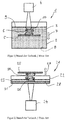
- the method shown is referred to as a top-down printing method.
- the device 1 for implementing this method comprises a trough 2 in which one polymerizable liquid 3 is given up.
- the liquid is preferably a resin which can be cured under UV radiation.
- An exposure source 4, which is mostly a DLP projector, is provided as the radiation source.
- the three-dimensional object 6 is built up in layers on a carrier platform 5, which is arranged within the liquid 3.
- the carrier platform 5 is moved in the direction 7 of the floor 8.
- the liquid 3 can flow in as a layer 10 between the object 6 and the surface 9 of the liquid.
- the post-flow layer 10 hardens according to the light area that falls on the surface 9 under the influence of radiation.
- the finished object 6 can be removed from the liquid 3. Since the layers 10 are hardened on the surface 9, there is no defined build-up layer. This limits the accuracy with which the object 6 is built.
- the method shown is referred to as a bottom-up printing method.
- the method is implemented with a device which is designated overall by the reference number 21.
- the exposure source 24 radiates from below onto the floor 28 of the tub 22.
- a building element 31 is arranged on the floor 28, on which the layers 30 of the object 26 are built.
- the object 26 is built up in layers between the building element 31 and a carrier platform 25. If a layer 30 has hardened or polymerized, the carrier platform is shifted upwards in the direction 27. Space is freed between the structural element 31 and the object 26, in which the polymerizable liquid 23 can flow.
- the layer 30 hardened on the structural element 31 must be lifted off the structural element 31. As a result, the structural element 31 is worn out and is to be regarded as a wearing part which has to be renewed at certain time intervals.
- the additive manufacturing device shown is designated overall by reference numeral 41.
- the device has components similar to the prior art described above.
- the new combination and arrangement of the components surprisingly leads to a multitude of advantages.
- a polymerizable liquid 43 is fed into a tub 42 or the container 42.
- a carrier platform 45 is arranged in the tub 42 so as to be displaceable in the vertical direction. This is illustrated by the directional arrow 47.
- the object 46 is built up in layers.
- the carrier platform 45 can also be moved out of the tub 42.
- the structural element 51 is arranged above the carrier platform 45 and not on the bottom 48 of the tub.
- the construction element 51 has a first and second side 53, 55.
- the liquid 43 is polymerized on the first side 53 to form a layer 50 of the object.
- the light from a light source 44 falls on the second side 55, which penetrates the structural element 51 and causes the hardening of the liquid 43 directly on the first side 53.
- the light source 44 is preferably a DLP projector, since it is an inexpensive mass product that meets all the requirements of the device 41.
- the elements of the device 41 are preferably arranged on a support 52 which is delimited by a housing 54 and is described in more detail in the next paragraph.
- the carrier platform 45 and the structural element 51 are preferably held on a common support 52.
- Support 52 is shown schematically in FIG Figure 3 represented with a rectangle.
- the support 52 can be, for example, a scaffold constructed from profiles, on which, in addition to the carrier platform 45 and the construction element 51, further elements of the production device 41, for example the DLP projector 44, can be arranged.
- the support 52 together with the carrier platform 45 and the structural element 51 can be displaced relative to the tub 42 along the arrow 47.
- the support 52 can be retracted into the trough 42 and fully extended from it. If the support 52 is extended out of the tub 42, the tub 42 is free of internals and can be quickly exchanged for another tub with a second liquid.
- the tub 42 can be exchanged for a further tub, it is therefore only necessary to raise the support 52 in the direction of arrow 47 or to move it out of the tub 42. If the further trough is placed in the holder provided for this purpose, the device is ready for operation again very quickly as soon as the support 52 has been moved into the further trough.
- the carrier platform 45 is slidably held on the support 52.
- the distance between the carrier platform 45 and the structural element 51 can thereby be changed.
- the three-dimensional object 46 can be constructed additively between the carrier platform 45 and the construction element 51 by successively shifting the carrier platform 45 downwards. This is indicated by a first shift arrow 62 in Figure 3 clarifies.
- the carrier platform 47 on the Support 52 moved in the direction of the building element 51 so that a further object can be built additively in layers. Since the carrier platform 45 is displaceably arranged on the support 52, which in turn is displaceable, the trough 42 can be freed of all internals by moving the support 52.
- the DLP projector 44 is also preferably arranged on the support 52 so as to be displaceable in the vertical direction. This is illustrated by a second shift arrow 72.
- the displaceability of the DLP projector 44 enables the resolution of the image projected onto the construction element 51 to be changed and adjusted quickly.
- the space which has become free on the base 48 can be used for arranging a magnetic stirrer 57. Therefore, polymerizable liquids 43 which have to be homogenized can also be processed in the device 41. Functional materials can be used which contain fillers 59. Resins with high viscosities can also be used.
- the magnetic stirrer 57 comprises a plate 58 which can be heated or cooled and on which the trough 42 can be placed. A sleeve surrounding the trough 42, which can be cooled or heated, is also conceivable for tempering the process. In addition, the temperature of the installation space 56 can still be adjustable.
- a holding housing 60 which surrounds the second side 55 and which is closed with respect to the construction space 56 and contains an adjustable optical system for optimizing the construction process.
- the carrier platform 45 can be moved up and down along the arrow 47.
- the construction element 51 can be arranged above the liquid surface 49 or the liquid level during the printing of the object 46.
- the object 46 wetted with liquid 43 is lifted out of the liquid with the aid of the carrier platform 45 and guided to the building element 51 for curing a layer 50.
- the object has to be immersed again in the liquid reservoir of the tub 42.
- the construction element 51 can also be arranged on the surface 49 or in the liquid 43. Then the layer build-up takes place in the liquid 43 and further liquid for the layer build-up can flow directly from the tub 42.
- the tub 42 can be removed from the device 41 together with the liquid 43 and the stirrer and another tub or vessel with another liquid and a stirrer can be placed in the device 41. A product change can therefore be carried out in a short time.
- the tub 42 provided can preferably be closed with a lid.
- the construction element 51 can be constructed from a separating membrane 61 ( Figure 4 ).
- the separating membrane 61 consists of an anti-adhesive material. Perfluoroethylene propylenes, for example, are particularly suitable. Depending on the liquid to be hardened, the material of the non-stick separating membrane can be adjusted. Since the structural element 51 is separated from the trough 42, the structural element 51 can also be quickly exchanged for another structural element.
- the structural element 51 can also comprise a carrier plate 63, for example made of glass ( Figure 4 ). This improves the static properties of the structural element 51.
- the separating membrane 61 is also easy to attach to the support plate 63 or to clamp or to replace.
- the carrier plate 63 can also be coated with a thin film 65 ( Figure 5 ).
- a thin film typically has a layer thickness of less than 10 ⁇ m.
- the construction element 51 can also be designed to vibrate in order to improve the detachment of the object layer 50 and to detach adhering air bubbles. If the polymerizable liquid used makes it necessary for an inhibiting gas to be present when building up the layer, a permeable membrane 67 can be provided on the building element 51 ( Figure 6 ).
- the structural element 51 can be inclined relative to the tub 42 set when the object 46 is brought up to the building element 51.
- the first side 53 of the structural element 51 can also be placed under reduced pressure or a protective gas can be applied to it.
- the area in which a negative pressure can preferably be built up is shown by the dashed area 69, which can be referred to as a negative pressure area. This area can be sealed off from the remaining volume within the housing.
- the vacuum area is preferably sealed by moving the support 52 into the tub 42. Because the vacuum region 69 has a reduced volume compared to the volume of the housing 54, the vacuum can be produced quickly.
- the vacuum region preferably includes the carrier platform 45 and the construction element 51 and in particular the first side 53 of the construction element 51. A negative pressure or a protective gas atmosphere can thereby be built up on the first side 53 of the building element 51.
Landscapes
- Chemical & Material Sciences (AREA)
- Engineering & Computer Science (AREA)
- Materials Engineering (AREA)
- Manufacturing & Machinery (AREA)
- Optics & Photonics (AREA)
- Mechanical Engineering (AREA)
- Physics & Mathematics (AREA)
- Health & Medical Sciences (AREA)
- Toxicology (AREA)
- Chemical Kinetics & Catalysis (AREA)
- Environmental & Geological Engineering (AREA)
- Analytical Chemistry (AREA)
- General Chemical & Material Sciences (AREA)
- Oil, Petroleum & Natural Gas (AREA)
- Laminated Bodies (AREA)
Description
- Die Erfindung betrifft eine additive Fertigungsvorrichtung zur schichtweisen Herstellung von dreidimensionalen Objekten aus einer polymerisierbaren (vernetzbaren) Flüssigkeit gemäss Oberbegriff des Anspruchs 1 sowie ein Verfahren zur schichtweisen Herstellung von dreidimensionalen Objekten aus einer polymerisierbaren Flüssigkeit gemäss Oberbegriff des Anspruchs 9.
- Der Stand der Technik im Bereich der additiven Fertigungsvorrichtungen wird momentan durch zwei Vorrichtungen und den damit in Verbindung stehenden Fertigungsverfahren gebildet.
- Im sogenannten Top-Down-Verfahren umfasst die additive Fertigungsvorrichtung eine Wanne in welcher ein UV-härtbares Harz aufgegeben ist. Das schichtweise aufzubauende Objekt wird am Oberflächenspiegel des Harzes Schicht für Schicht aufgebaut. Dabei wird die Oberfläche des Harzes mit einer UV-Lichtquelle in der Gestalt der Schicht bestrahlt, welche aufgebaut werden soll. Dadurch härtet die Schicht in der gewünschten Gestalt an der Oberfläche des Harzes aus. Das Objekt wird auf einer Bauplattform aufgebaut, wobei die Plattform von der Oberfläche des Harzes wegbewegt wird, solange bis das Objekt fertig Schicht für Schicht aufgebaut ist. Das Top-Down-Verfahren hat den Vorteil, dass keine Verschleissteile vorhanden sind. Wegen der an der Harzoberfläche vorhandenen Oberflächenspannung ist die Konturgenauigkeit der mit dem Top-Down-Verfahren hergestellten Objekte jedoch beschränkt. Da die Oberfläche des Harzes keine definierte Oberfläche darstellen kann, ist die Oberfläche jeder Schicht zwangsläufig relativ ungenau.
- Um die Konturgenauigkeit der Objekte zu verbessern, wurde das sogenannte Bottom-Up-Verfahren entwickelt. Dabei werden die aufzubauenden Objektschichten nicht an der Harzoberfläche sondern am Boden einer Harzwanne aufgebaut. Da das Objekt aufgebaut wird, indem die Plattform vom Boden der Harzwanne nach oben weg bewegt wird, ist es ausreichend, wenn im Vergleich zum Top-Down-Verfahren eine geringe Menge Harz in der Wanne vorhanden ist. Der Boden muss mit Harz bedeckt sein, damit das Harz zwischen Boden und Objekt jederzeit nachfliesen kann, um eine Schicht aufzubauen. Die UV-Lichtquelle ist unterhalb des Bodens angeordnet, weshalb dieser für das UV-Licht durchgängig sein muss.
- Um jede ausgehärtete Schicht vom Boden ablösen zu können, muss der Boden mit einer Trennschicht versehen sein. Die Trennschicht stellt eine definierte Oberfläche für jede ausgehärtete Objektschicht dar. Dadurch besitzt das im Bottom-Up-Verfahren hergestellte Objekt eine hohe Massgenauigkeit. Die Trennschicht wird jedoch bei jedem Ablösen einer ausgehärteten Schicht mechanisch belastet und ist daher ein Verschleissteil, das immer wieder durch eine neue Trennschicht ersetzt werden muss. Ein weiterer Nachteil besteht darin, dass als Baumaterial nur einfache Harze verwendbar sind, da sich Harze mit Füllstoffen in dieser Vorrichtung nicht homogenisieren lassen und sich Harze mit erhöhten Viskositäten nicht verarbeiten lassen.
- In der
EP 0 467 100 A1 ist eine additive Fertigungsvorrichtung offenbart, bei welcher ein dreidimensionales Objekt in Schichten zwischen einer transparenten Barriereplatte und einem Objekttisch aufgebaut wird. Der Objekttisch ist in einem mit der auszuhärtendenden Flüssigkeit gefüllten Reaktor positioniert. Die Platte ist an der Oberfläche der Flüssigkeit positioniert. Die Platte wird von oben einer Strahlung ausgesetzt, welche dazu führt, dass unmittelbar an der unteren Seite der Platte die Flüssigkeit zu einer Schicht mit definierten Aussenkonturen ausgehärtet wird. Mit Hilfe einer Rütteleinrichtung wird die Platte in Vibration versetzt, wodurch sie sich von der ausgehärteten Schicht des dreidimensionalen Objekts lösen lässt. Der Objekttisch wird dann um die Schichtdicke der nächsten Objektschicht abgesenkt, wodurch Flüssigkeit zwischen die Platte und die oberste ausgehärtete Schicht nachfliessen kann. Dann wird die nächste Schicht ausgehärtet, solange bis das dreidimensionale Objekt fertig gestellt ist. Die Vorrichtung ermöglicht es, dass die ausgehärteten Objektschichten schonend von der Platte gelöst werden können. Dadurch sind detailgetreue und exakte Objekte herstellbar. Allerdings gestaltet sich der Wechsel unterschiedlicher unter Strahlung aushärtbarer Flüssigkeiten, wenn überhaupt möglich, sehr aufwendig. - Die
US 5,174,943 beschreibt eine Vorrichtung zum Herstellen eines dreidimensionalen Objektes mittels selektiver Verfestigung einer Oberflächenschicht eines fluiden Mediums, welches durch ein verfestigendes Medium verfestigbar ist, um das Objekt aus überlagerten verfestigten Objektschichten aufzubauen. Die Vorrichtung umfasst einen Behälter für das fluide Medium, ein Mittel zum selektiven Aufbringen eines verfestigenden Mediums auf eine Arbeitsfläche des fluiden Mediums, um eine verfestigte Objektschicht zu bilden und ein Steuermittel, um ein Trägermittel in fortschreitenden Schritten von der genannten Oberfläche fort zu bewegen, um es frischem fluiden Medium zu erlauben, nach jeder schrittweisen Bewegung zur selektiven Verfestigung zugeführt zu werden. Es können mehrere Behälter verwendet werden, wobei jeder Behälter einen verschiedenen Typ des aushärtbaren Materials beinhaltet, das automatisch beim stereolithographischen System ausgewählt werden kann. - Aus den Nachteilen des beschriebenen Stands der Technik resultiert die die vorliegende Erfindung initiierende Aufgabe eine gattungsgemässe additive Fertigungsvorrichtung weiterzuentwickeln, welche die oben beschriebenen Nachteile nicht aufweist. Ein weiteres Ziel ist es, eine additive Fertigungsvorrichtung vorzuschlagen, welche eine grosse Anzahl von unterschiedlichen Funktionsmaterialien als Werkstoffe bzw. Baumaterialien verarbeiten kann und die Möglichkeit zu schaffen, zwischen den unterschiedlichen Werkstoffen rasch wechseln zu können.
- Die Lösung der gestellten Aufgabe gelingt bei einer additiven Fertigungsvorrichtung zur schichtweisen Herstellung von dreidimensionalen Objekten aus einer polymerisierbaren Flüssigkeit dadurch, dass die Fertigungsvorrichtung wenigstens zwei mit unterschiedlichen Flüssigkeiten gefüllte Wannen umfasst, wobei die Wanne, welche mit einer ersten Flüssigkeit gefüllt ist, gegen eine weitere Wanne austauschbar ist, welche mit einer zweiten Flüssigkeit gefüllt ist und dass die Trägerplattform und das Aufbauelement an einem gemeinsamen Support gehalten sind, welcher Support in die Wanne ein- und ausfahrbar ist. Die Wanne lässt sich rasch und sauber gegen eine andere Wanne mit einer anderen Flüssigkeit tauschen, da sich in der Wanne lediglich die Flüssigkeit befindet. Der Flüssigkeitstausch kann daher nicht durch mühsames Entleeren, Säubern und Neubefüllen der Wanne bzw. des Behälters erfolgen, sondern durch einfaches Austauschen zweier Behälter. Der rückgestellte Behälter bzw. die Wanne sind verschliessbar und daher nach Bedarf lagerbar. So kann eine breite Produktpalette an polymerisierbaren Flüssigkeiten mit oder ohne Füllstoffen abrufbar sein. Jeder Behälter kann mit einem eigenen Rührfisch versehen sein, damit sich die Entnahme und die Reinigung des Rührfisches erübrigt. Durch die Möglichkeit die Position der Wanne relativ zu dem Aufbauelement zu verändern, ist die Vorrichtung äusserst flexibel und kann an die unterschiedlichsten polymerisierbaren bzw. vernetzbaren Flüssigkeiten und die unterschiedlichsten herzustellenden dreidimensionalen Objekte angepasst werden. Das Aufbauelement lässt sich während des Druckprozesses oberhalb der Wanne bzw. der Flüssigkeit, auf dem Flüssigkeitsspiegel oder in der Flüssigkeit anordnen.
- Durch Hochfahren des Supports werden gleichzeitig alle Einbauten aus der Wanne entfernt. Die Wanne kann einfach aus ihrer Halterung mitsamt der sich darin befindenden polymerisierbaren Flüssigkeit entnommen werden. Das einzelne zeitintensive Ausbauen von Einbauten aus der Wanne kann entfallen. Genauso einfach lässt sich eine weitere Wanne mit einer anderen Flüssigkeit in die dafür vorgesehene Halterung stellen. Zum Start des additiven Aufbaus eines Objekts muss lediglich der Support in die Wanne eingefahren werden. Das Einfahren des Supports hat auch den Vorteil, dass dadurch die Flüssigkeit durchmischt wird und eine zusätzliche Homogenisierung der Flüssigkeit nicht zwangsläufig vorhanden sein muss.
- In einer weiteren bevorzugten Ausführungsform der Erfindung ist die Trägerplattform zumindest in vertikaler Richtung verschiebbar an dem Support gehalten, wodurch der Abstand zwischen der Trägerplattform und dem Aufbauelement veränderbar ist. Der Support beinhaltet daher auch die lineare Bewegungsvorrichtung, welche zum Aufbau eines Objektes in Schichten notwendig ist. Der Support bildet mit der Trägerplattform und dem Aufbauelement eine Einheit, welche mit einer einzigen vertikalen Bewegung aus der Wanne einfahr- und ausfahrbar ist.
- Als vorteilhaft hat es sich erwiesen, wenn die Strahlenquelle zumindest in vertikaler Richtung verschiebbar an dem Support gehalten ist. Die Verschiebbarkeit der Strahlenquelle relativ zu dem Aufbauelement bewirkt, dass sich die Auflösung des Bildes, welches als Vorlage zur Bildung einer Objektschicht dient, rasch einstellen und anpassen lässt.
- Die Erfindung zeichnet sich bevorzugt dadurch aus, dass an der Unterseite des Bodens eine temperierbare Homogenisierungseinheit zur Homogenisierung und zur Temperatureinstellung der polymerisierbaren Flüssigkeit angeordnet ist. Die Verarbeitungsparameter der Flüssigkeit können daher individuell an die Flüssigkeitseigenschaften angepasst werden. Insbesondere kann die Viskosität der Flüssigkeit auf einen Wert eingestellt werden, bei welchem sie sich besonders gut zu Schichten polymerisieren lässt. Auch können Flüssigkeiten mit Füllstoffen und/oder hohen Viskositäten verarbeitet werden, da sich die Füllstoffe durch den Homogenisator gleichmässig in der Flüssigkeit verteilen lassen. Es lassen sich auch Funktionsmaterialien verarbeiten, welche bei Vorrichtungen des Stands der Technik nicht oder nur sehr schwer verarbeitbar sind. So ist es denkbar auch Flüssigkeiten zu verarbeiten, welche keramische, metallische oder mineralische Füllstoffe aufweisen.
- Als zweckdienlich hat es sich erwiesen, wenn die Homogenisierungseinheit ein Magnetrührer ist. Magnetrührer zählen zu weit verbreiten Produkten im Laborbedarf und sind dementsprechend kostengünstig und ausgereift. Der Magnetrührer umfasst eine beheizbare oder kühlbare Platte und einen sogenannten Rührfisch. Der Rührfisch wird in die Flüssigkeit eingelegt und wird durch magnetische Kraft rotiert. Die Wanne wird auf die Platte gestellt und kann für einen Produktwechsel jederzeit entnommen werden. Denkbar sind als Homogenisator auch eine Ultraschalleinwirkung auf die Flüssigkeit, direkt mechanisch bewegte Rührer oder eine Bewegung des Behälters.
- Die Erfindung zeichnet sich bevorzugt dadurch aus, dass die Wanne in der Höhe verschiebbar ist. Dadurch können drei Produktionsmodi realisiert werden. Einerseits kann das Aufbauelement durch die Position der Wanne oberhalb des Flüssigkeitsspiegels angeordnet werden. Dann erfolgt der Schichtaufbau ausserhalb der Flüssigkeit. Andererseits kann die Wanne auch derart positioniert sein, dass das Aufbauelement auf dem Flüssigkeitsspiegel zu liegen kommt. Dann erfolgt der Schichtaufbau innerhalb der Flüssigkeit. Auch kann die Wanne derart positioniert werden, dass das Aufbauelement innerhalb der Flüssigkeit zu liegen kommt. Der Produktionsmodus kann daher an die unterschiedlichsten Eigenschaften der polymerisierbaren Flüssigkeit angepasst werden. Auch ist die Wanne durch Ihre Verschiebbarkeit besonders einfach aus der Vorrichtung zu entnehmen.
- Zweckmässigerweise ist das Aufbauelement ausserhalb oder innerhalb der Wanne anordenbar. Am zweckmässigsten werden diese Anordnungen durch die vertikale Verschiebbarkeit der Wanne erreicht. Denkbar wäre es auch, dass das Aufbauelement vertikal verschiebbar ist. So lassen sich die weiter oben beschriebenen Produktionsmodi umsetzen.
- In einer weiteren bevorzugten Ausführungsform umfasst das Aufbauelement eine Trennmembran. Die Trennmembran ist bevorzugt aus einem Antihaftmaterial aufgebaut, von welchem sich die ausgehärteten auspolymerisierten Objektschichten leicht lösen.
- Besonders bevorzugt ist es, wenn die Trennmembrane aus Perfluorethylenpropylen (FEP) besteht, da dieses Material gegenüber vielen UV-aushärtbaren Harzen antihaftend wirkt.
- Zweckmässigerweise ist die Trennmembrane gaspermeabel, um an der ersten Seite des Aufbauelements Hemmmaterialien bereitzustellen. Solche Hemmmaterialien ermöglichen die gezielte Polymerisierung der Flüssigkeit, wenn sie aus dieser entweichen.
- Als vorteilhaft erweist es sich, wenn das Aufbauelement eine Trägerplatte umfasst. Die Trägerplatte dient der Stabilisierung des Aufbauelements, damit dieses separat und eigenstabil in der Vorrichtung anordenbar ist. Die Trennmembran kann an der Trägerplatte aufgespannt werden. Bevorzugt ist die Trägerplatte aus einem transparenten Material, beispielsweise einem Glas oder einem Kunststoff.
- Zweckmässigerweise kann die Antihaftbeschichtung als eine Dünnfilmbeschichtung realisiert sein. Aus der Dünnschichttechnologie ist eine grosse Anzahl von Materialien mit guten antihaftenden Eigenschaften bekannt.
- In einer weiteren bevorzugten Ausführungsform ist das Aufbauelement in Vibration versetzbar. Die Vibration führt dazu, dass sich die polymerisierten Objektschichten leichter von dem Aufbauelement lösen. Auch ist die Vibration nützlich, wenn sich an dem Aufbauelement anhaftende Gasblasen lösen sollen.
- Als vorteilhaft erweist es sich, wenn der Anstellwinkel des Aufbauelements relativ zur Wanne verstellbar ist. Wird das Objekt an die erste Seite des Aufbauelements gefahren, so ist es von Vorteil, wenn diese schräg gestellt ist, um Gasblasen von der ersten Seite zu verdrängen. Während des Aufbaus einer weiteren Objektschicht ist das Aufbauelement wieder horizontal zu stellen.
- Ein weiterer Aspekt der Erfindung betrifft eine additive Fertigungsvorrichtung gemäss Oberbegriff des Anspruchs 1 bei welcher an der Unterseite des Bodens eine Temperierungseinheit zur Temperatureinstellung der polymerisierbaren Flüssigkeit angeordnet ist. Diese Vorrichtung lässt sich auch mit den Merkmalen der Unteransprüche 2 bis 8 kombinieren.
- Ein weiterer Aspekt der Erfindung betrifft ein Verfahren zur schichtweisen Herstellung von dreidimensionalen Objekten aus einer polymerisierbaren Flüssigkeit gemäss Oberbegriff des Anspruchs 9. Die Wanne wird unterhalb des Aufbauelements angeordnet und die Trägerplattform wird während des schichtenweisen Aufbaus des Objektes in Richtung des Bodens der Wanne bewegt. Diese Anordnung ermöglicht es, das Objekt mit einer hohen Genauigkeit und Masshaltigkeit herzustellen, ein sauberes Handling der polymerisierbaren Flüssigkeit und die Verwendung vieler unterschiedlicher Funktionsmaterialien zum Aufbau des Objekts. Zum Wechsel der polymerisierbaren Flüssigkeit wird die Wanne gegen eine weitere Wanne mit einer anderen polymerisierbaren Flüssigkeit getauscht. Die Wanne bzw. der Behälter muss nicht entleert, gereinigt und mit einer anderen Flüssigkeit befüllt werden, sondern wird einfach verschlossen zur Seite gestellt. Der Produktionswechsel kann daher sehr rasch und einfach erfolgen. Für ein grosses Produktportfolio kann eine Vielzahl von mit polymerisierbaren Flüssigkeiten gefüllten Behältern oder Wannen auf Lager gestellt sein. Selbstverständlich können die Grösse der Behälter und die Füllvolumen nach Bedarf variieren.
- Erfindungsgemäss wird zum Wechsel der Wanne gegen eine weitere Wanne ein Support, an welchem die Trägerplattform und das Aufbauelement gehalten sind, aus der Wanne ausgefahren und in die weitere Wanne eingefahren. Dadurch bewirkt eine einzige translatorische Bewegung des Supports, dass die Wanne aus ihrer Halterung entnehmbar ist, ohne dass weitere Einbauten aus dieser entfernt werden müssten.
- In einer besonders bevorzugten Ausführungsform wird zur Einstellung der optimalen Prozessparameter der polymerisierbaren Flüssigkeit die Flüssigkeit in der Wanne homogenisiert und auf eine Prozesstemperatur eingestellt und die Bauraumtemperatur geregelt. Als Bauraum ist der Raum zu verstehen, welcher von einem Gehäuse begrenzt wird und in welchem die Bauelemente der Vorrichtung mit Ausnahme der Lichtquelle angeordnet sind. Die Einstellung der Prozessparameter kann durch einen Homogenisator, insbesondere einen Magnetrührer, erfolgen. Der Rührfisch des Magnetrührers kann am Boden der Wanne rühren, da das Objekt oberhalb der Trägerplattform auf dieser aufgebaut wird und deshalb nicht im Weg ist. Auch kann die Temperatur durch eine Manschette eingestellt werden, welche beheizt oder gekühlt werden kann und die Wanne umschliessen. Die Verwendung und Auswahl der polymerisierbaren Flüssigkeiten ist daher nicht auf einphasige Harze beschränkt. Es können auch jegliche mehrphasige Funktionsmaterialien mit Füllstoffen oder Harze mit hohen Viskositäten verarbeitet werden
- Die Erfindung zeichnet sich bevorzugt auch dadurch aus, dass die Höhe der Wanne zu dem Aufbauelement während der Objektherstellung derart eingestellt wird, dass das Aufbauelement oberhalb des sich in der Wanne bildenden Flüssigkeitsspiegels, auf dem Flüssigkeitsspiegel oder in der Flüssigkeit positioniert wird. Es stehen, wie bereits weiter oben ausgeführt, daher drei Produktionsmodi zur Auswahl. Die Objektschichten können durch die vertikale Bewegbarkeit der Wanne ausserhalb oder innerhalb der polymerisierbaren Flüssigkeit aufgebaut werden. Dies führt zu einer zusätzlichen Flexibilität, um das Druckverfahren optimal an die einzusetzenden Flüssigkeiten anpassen zu können.
- Zweckmässigerweise wird auf der ersten Seite des Aufbauelements ein Unterdruck oder eine Schutzgasatmosphäre aufgebaut. Unerwünschte Gasblasen an dem Aufbauelement können so wirksam verdrängt bzw. aufgelöst werden. Dadurch steht während des Produktionsverfahrens immer ein sauberes Aufbauelement zur Verfügung.
- Weitere Vorteile und Merkmale ergeben sich aus der nachfolgenden Beschreibung eines Ausführungsbeispiels der Erfindung unter Bezugnahme auf die schematischen Darstellungen. Es zeigen in nicht massstabsgetreuer Darstellung:
- Figur 1:
- eine Prinzipdarstellung des Top-down Druckverfahrens;
- Figur 2:
- eine Prinzipdarstellung des Bottom-Up-Druckverfahrens;
- Figur 3:
- eine Prinzipdarstellung des neuen Druckverfahrens und
- Figur 4-6:
- unterschiedliche Ausführungsformen eines Aufbauelements.
- In den
Figuren 1 und 2 sind zwei additive Fertigungsvorrichtungen zur schichtweisen Herstellung von dreidimensionalen Objekten, wie sie aus dem Stand der Technik bekannt sind, gezeigt. Die Vorrichtung gemäss derFigur 1 ist mit dem Bezugszeichen 1 bezeichnet wohingegen die Vorrichtung gemäss derFigur 2 mit dem Bezugszeichen 21 bezeichnet ist. - Das in
Figur 1 gezeigte Verfahren wird als Top-Down-Druckverfahren bezeichnet. Die Vorrichtung 1 zur Umsetzung dieses Verfahrens umfasst eine Wanne 2, in welcher eine polymerisierbare Flüssigkeit 3 aufgegeben ist. Bevorzugt handelt es sich bei der Flüssigkeit um ein Harz, welches unter UV-Bestrahlung aushärtbar ist. Als Strahlenquelle ist eine Belichtungsquelle 4 vorgesehen, bei welcher es sich zumeist um einen DLP-Beamer handelt. Auf einer Trägerplattform 5, welche innerhalb der Flüssigkeit 3 angeordnet ist, wird das dreidimensionale Objekt 6 schichtweise aufgebaut. Die Trägerplattform 5 wird in Richtung 7 des Bodens 8 bewegt. Dabei kann die Flüssigkeit 3 zwischen dem Objekt 6 und der Oberfläche 9 der Flüssigkeit als eine Schicht 10 nachfliessen. Die nachgeflossene Schicht 10 härtet gemäss der Lichtfläche, welche auf die Oberfläche 9 fällt, unter dem Strahleneinfluss aus. Das fertige Objekt 6 kann aus der Flüssigkeit 3 entnommen werden. Da die Schichten 10 an der Oberfläche 9 ausgehärtet werden, existiert keine definierte Aufbauschicht. Dadurch sind der Genauigkeit, mit welchem das Objekt 6 aufgebaut wird, Grenzen gesetzt. - Das in
Figur 2 gezeigte Verfahren wird als Bottom-Up-Druckverfahren bezeichnet. Das Verfahren wird mit einer Vorrichtung umgesetzt, welche gesamthaft mit dem Bezugszeichen 21 bezeichnet ist. Die Belichtungsquelle 24 strahlt von unten auf den Boden 28 der Wanne 22. Am Boden 28 ist ein Aufbauelement 31 angeordnet, an welchem die Schichten 30 des Objektes 26 aufgebaut werden. Das Objekt 26 wird zwischen dem Aufbauelement 31 und einer Trägerplattform 25 schichtenweise aufgebaut. Ist eine Schicht 30 ausgehärtet bzw. polymerisiert, so wird die Trägerplattform in Richtung 27 nach oben verschoben. Zwischen dem Aufbauelement 31 und dem Objekt 26 wird Platz frei gegeben, in welchen die polymerisierbare Flüssigkeit 23 nachfliessen kann. Die an dem Aufbauelement 31 ausgehärtete Schicht 30 muss von dem Aufbauelement 31 abgehoben werden. Dadurch wird das Aufbauelement 31 abgenutzt und ist als ein Verschleissteil zu erachten, welches in bestimmten Zeitintervallen erneuert werden muss. - Die in
Figur 3 gezeigte additive Fertigungsvorrichtung ist gesamthaft mit dem Bezugszeichen 41 bezeichnet. Grundsätzlich weist die Vorrichtung ähnliche Bauelemente wie der weiter oben beschriebene Stand der Technik auf. Die neue Kombination und Anordnung der Bauelemente führt jedoch in überraschender Weise zu einer Vielzahl von Vorteilen. - In einer Wanne 42 bzw. dem Behälter 42 ist eine polymerisierbare Flüssigkeit 43 aufgegeben. In der Wanne 42 ist eine Trägerplattform 45 in vertikaler Richtung verschiebbar angeordnet. Dies ist durch den Richtungspfeil 47 verdeutlicht. Auf der Trägerplattform 45 wird das Objekt 46 schichtweise aufgebaut. Wie in
Figur 3 gezeigt, kann die Trägerplattform 45 auch aus der Wanne 42 herausgefahren werden. Im Gegensatz zum Stand der Technik ist das Aufbauelement 51 oberhalb der Trägerplattform 45 angeordnet und nicht am Boden 48 der Wanne. Das Aufbauelement 51 weist eine erste und zweite Seite 53,55 auf. Die Flüssigkeit 43 wird an der ersten Seite 53 zu einer Schicht 50 des Objekts polymerisiert. Auf die zweite Seite 55 fällt das Licht einer Lichtquelle 44, welche das Aufbauelement 51 durchdringt und die Aushärtung der Flüssigkeit 43 direkt an der ersten Seite 53 bewirkt. Bevorzugt ist die Lichtquelle 44 ein DLP-Beamer, da es sich dabei um ein kostengünstiges Massenprodukt handelt, welches alle Anforderungen der Vorrichtung 41 erfüllt. Die Elemente der Vorrichtung 41 sind bevorzugt an einem Support 52 angeordnet, welcher von einem Gehäuse 54 begrenzt ist und im nächsten Absatz genauer beschrieben wird. - Die Trägerplattform 45 und das Aufbauelement 51 sind bevorzugt an einem gemeinsamen Support 52 gehalten. Der Support 52 ist schematisch in
Figur 3 mit einem Rechteck dargestellt. Der Support 52 kann beispielsweise ein aus Profilen aufgebautes Gerüst sein, an welchem neben der Trägerplattform 45 und dem Aufbauelement 51 noch weitere Elemente der Fertigungsvorrichtung 41, beispielsweise der DLP-Beamer 44, angeordnet sein können. Der Support 52 ist mitsamt der Trägerplattform 45 und dem Aufbauelement 51 relativ zu der Wanne 42 entlang des Pfeils 47 verschiebbar. Der Support 52 ist in die Wanne 42 einfahrbar und aus dieser vollständig ausfahrbar. Ist der Support 52 aus der Wanne 42 ausgefahren, so ist die Wanne 42 frei von Einbauten und kann rasch gegen eine weitere Wanne mit einer zweiten Flüssigkeit getauscht werden. Damit die Wanne 42 gegen eine weitere Wanne austauschbar ist, ist daher lediglich der Support 52 in Richtung des Pfeils 47 hochzufahren bzw. aus der Wanne 42 auszufahren. Ist die weitere Wanne in der dafür vorgesehenen Halterung platziert, so ist die Vorrichtung sehr rasch wieder betriebsbereit, sobald der Support 52 in die weitere Wanne eingefahren ist. - Die Trägerplattform 45 ist verschiebbar an dem Support 52 gehalten. Dadurch lässt sich der Abstand zwischen der Trägerplattform 45 und dem Aufbauelement 51 verändern. Das dreidimensionale Objekt 46 kann zwischen der Trägerplattform 45 und dem Aufbauelement 51 additiv aufgebaut werden, indem die Trägerplattform 45 sukzessive nach unten verschoben wird. Dies ist durch einen ersten Verschiebepfeil 62 in
Figur 3 verdeutlicht. Nach Fertigstellung des Objekts 46 wird die Trägerplattform 47 an dem Support 52 in Richtung des Aufbauelements 51 verschoben, damit ein weiteres Objekt additiv in Schichten aufgebaut werden kann. Da die Trägerplattform 45 an dem Support 52 verschiebbar angeordnet ist, welcher seinerseits verschiebbar ist, lässt sich die Wanne 42 durch Verschieben des Supports 52 von allen Einbauten befreien. - Auch der DLP-Beamer 44 ist bevorzugt in vertikaler Richtung verschiebbar an dem Support 52 angeordnet. Dies ist durch einen zweiten Verschiebepfeil 72 verdeutlicht. Die Verschiebbarkeit des DLP-Beamers 44 ermöglicht die Auflösung des auf das Aufbauelement 51 projizierten Bildes rasch ändern und einstellen zu können.
- Da der Boden 48 frei von dem Aufbauelement 51 ist und das Aufbauelement 51 separat von der Wanne 42 in der Vorrichtung angeordnet ist, kann der am Boden 48 frei gewordene Platz zur Anordnung eines Magnetrührers 57 genutzt werden. In der Vorrichtung 41 können daher auch polymerisierbare Flüssigkeiten 43 verarbeitet werden, welche homogenisiert werden müssen. Es können Funktionsmaterialien eingesetzt werden, welche Füllstoffe 59 enthalten. Auch können Harze mit hohen Viskositäten eingesetzt werden. Der Magnetrührer 57 umfasst eine Platte 58, welche geheizt oder gekühlt werden kann und auf welcher die Wanne 42 abstellbar ist. Zur Temperierung des Prozesses ist auch eine die Wanne 42 umgebende Manschette denkbar, welche gekühlt oder beiheizt werden kann. Zusätzlich kann die Temperatur des Aufbauraums 56 noch einstellbar sein. Durch die Möglichkeit, die Prozesstemperatur genau auf die zu verarbeitende polymerisierbare Flüssigkeit 43 einzustellen, lassen sich eine Vielzahl von Flüssigkeiten 43 vollständig homogenisieren und auf die optimale Verarbeitungstemperatur einstellen. Oberhalb des Aufbauelements 51 kann ein die zweite Seite 55 umschliessendes Haltegehäuse 60 vorgesehen sein, welches gegenüber dem Aufbauraum 56 geschlossen ist und eine verstellbare Optik zur Optimierung des Aufbauprozesses beinhaltet.
- Es ist nicht nur die Trägerplattform 45 sondern auch die Wanne 42 entlang des Pfeils 47 nach oben und unten verschiebbar. Dadurch kann das Aufbauelement 51 während des Druckens des Objektes 46 oberhalb der Flüssigkeitsoberfläche 49 bzw. des Flüssigkeitsspiegels angeordnet sein. Zum Schichtaufbau wird das mit Flüssigkeit 43 benetzte Objekt 46 aus der Flüssigkeit mit Hilfe der Trägerplattform 45 gehoben und an das Aufbauelement 51 zur Aushärtung einer Schicht 50 geführt. Für eine weitere Schicht 50 muss das Objekt wieder in das Flüssigkeitsreservoir der Wanne 42 getaucht werden.
- Wenn es für den Objektdruck erforderlich ist, kann das Aufbauelement 51 jedoch auch auf der Oberfläche 49 oder in der Flüssigkeit 43 angeordnet werden. Dann erfolgt der Schichtaufbau in der Flüssigkeit 43 und weitere Flüssigkeit zum Schichtaufbau kann direkt aus der Wanne 42 nachfliessen.
- Ein weiterer Vorteil, dass das Aufbauelement 51 von der Wanne 42 separiert ist, liegt darin, dass die Wanne 42 aus der Vorrichtung 41 mitsamt der Flüssigkeit 43 und dem Rührer entnommen werden kann und eine andere Wanne bzw. Gefäss mit einer anderen Flüssigkeit und einem Rührer in die Vorrichtung 41 gestellt werden kann. Ein Produktwechsel lässt sich daher in kurzer Zeit durchführen. Die beigestellte Wanne 42 ist bevorzugt mit einem Deckel verschliessbar.
- Das Aufbauelement 51 kann aus einer Trennmembran 61 aufgebaut sein (
Figur 4 ). Um die gedruckten Schichten 50 besonders schonend und leicht von der Trennmembran ablösen zu können, besteht die Trennmembran 61 aus einem antihaftenden Material. Besonders geeignet sind beispielsweise Perfluorethylenpropylene. In Abhängigkeit von der auszuhärtenden Flüssigkeit kann das Material der antihaftenden Trennmembran angepasst werden. Da das Aufbauelement 51 von der Wanne 42 separiert ist, lässt sich das Aufbauelement 51 auch rasch gegen ein anderes Aufbauelement tauschen. Das Aufbauelement 51 kann neben der Trennmembran 61 auch eine Trägerplatte 63, beispielsweise aus Glas, umfassen (Figur 4 ). Dadurch werden die statischen Eigenschaften des Aufbauelements 51 verbessert. Auch ist die Trennmembran 61 einfach an der Trägerplatte 63 zu befestigen bzw. aufzuspannen oder auszutauschen. - Für gute Antihafteigenschaften kann die Trägerplatte 63 auch mit einem Dünnfilm 65 beschichtet sein (
Figur 5 ). Ein Dünnfilm besitzt typischerweise eine Schichtdicke von weniger als 10 µm. Das Aufbauelement 51 kann auch vibrierend ausgeführt sein, um das Lösen der Objektschicht 50 zu verbessern und anhaftende Luftblasen abzulösen. Macht es die verwendete polymerisierbare Flüssigkeit notwendig, dass ein Hemmgas beim Schichtaufbau vorhanden ist, so kann eine permeable Membran 67 an dem Aufbauelement 51 vorgesehen sein (Figur 6 ). - Um an dem Aufbauelement 51 oder an der obersten Schicht des Objektes 46 anhaftende Luftblasen zu entfernen, lässt sich das Aufbauelement 51 relativ zur Wanne 42 schräg stellen, wenn das Objekt 46 an das Aufbauelement 51 herangeführt wird. Um die unerwünschten Blasen zu entfernen, lässt sich die erste Seite 53 des Aufbauelements 51 auch unter Unterdruck setzen oder kann mit einem Schutzgas beaufschlagt werden. Der Bereich in welchem bevorzugt ein Unterdruck aufgebaut werden kann, ist durch den gestrichelten Bereich 69, welcher als Unterdruckbereich bezeichnet werden kann, gezeigt. Dieser Bereich ist gegenüber dem restlichen Volumen innerhalb des Gehäuses abdichtbar. Der Unterdruckbereich wird bevorzugt durch Einfahren des Supports 52 in die Wanne 42 abgedichtet. Dadurch, dass der Unterdruckbereich 69 ein reduziertes Volumen im Vergleich zum Volumen des Gehäuses 54 aufweist, ist der Unterdruck rasch herstellbar. Der Unterdruckbereich schliesst bevorzugt die Trägerplattform 45 und das Aufbauelement 51 und insbesondere die erste Seite 53 des Aufbauelements 51 ein. An der ersten Seite 53 des Aufbauelements 51 ist dadurch ein Unterdruck oder eine Schutzgasatmosphäre aufbaubar.
-
- 1
- Top-Down-Druckvorrichtung
- 2
- Wanne
- 3
- Polymerisierbare Flüssigkeit
- 4
- Belichtungsquelle
- 5
- Trägerplattform
- 6
- Dreidimensionales Objekt
- 7
- Richtungspfeil
- 8
- Boden der Wanne
- 9
- Oberfläche der Flüssigkeit
- 10
- Schicht des Objekts
- 21
- Bottom-Up-Druckvorrichtung
- 22
- Wanne
- 23
- Polymerisierbare Flüssigkeit
- 24
- Lichtquelle
- 25
- Trägerplattform
- 26
- Dreidimensionales Objekt
- 27
- Richtungspfeil
- 28
- Boden der Wanne
- 30
- Schicht des Objekts
- 31
- Aufbauelement
- 41
- Additive Fertigungsvorrichtung
- 42
- Wanne, Behälter
- 43
- Polymerisierbare Flüssigkeit
- 44
- Lichtquelle
- 45
- Trägerplattform
- 46
- Dreidimensionales Objekt
- 47
- Richtungspfeil
- 48
- Boden der Wanne
- 49
- Flüssigkeitsoberfläche
- 50
- Schicht des Objekts
- 51
- Aufbauelement
- 52
- Support
- 53
- Erste Seite des Aufbauelements
- 54
- Gehäuse
- 55
- Zweite Seite des Aufbauelements
- 56
- Aufbauraum
- 57
- Magnetrührer
- 58
- Platte
- 59
- Füllstoffe
- 60
- Aufbaugehäuse
- 61
- Trennmembran
- 62
- Erster Verschiebepfeil
- 63
- Trägerplatte
- 65
- Dünnfilm
- 67
- Permeable Membran
- 69
- Unterdruckbereich
- 72
- Zweiter Verschiebepfeil
Claims (11)
- Additive Fertigungsvorrichtung (21,41) zur schichtweisen Herstellung von dreidimensionalen Objekten (26,46) aus einer polymerisierbaren Flüssigkeit (23,43) umfassend- eine Wanne (22,42) mit einem Boden (28,48) zur Aufnahme der Flüssigkeit (23,43),- eine Trägerplattform (25,45) auf welcher das Objekt (26,46) aufgebaut wird und welche relativ zu der Wanne (22,42) in der Höhe verschiebbar ist,- ein Aufbauelement (31,51) mit einer ersten und zweiten Seite (53,55), an welcher die Flüssigkeit (23,43) an der ersten Seite (53) zu einer Objektschicht (30,50) polymerisiert und- eine Strahlenquelle (24,44), welche die zweite Seite (55) des strahlendurchlässigen Aufbauelements (31,51) bestrahlt, wobei das Aufbauelement (51) oberhalb der Trägerplattform (45) angeordnet ist und der Abstand zwischen dem Aufbauelement (51) und der Wanne (42) relativ zueinander veränderbar ist,dadurch gekennzeichnet,
dass die Fertigungsvorrichtung (41) wenigstens zwei mit unterschiedlichen Flüssigkeiten gefüllte Wannen umfasst, wobei die Wanne (42), welche mit einer ersten Flüssigkeit (43) gefüllt ist, gegen eine weitere Wanne austauschbar ist, welche mit einer zweiten Flüssigkeit gefüllt ist und
dass die Trägerplattform (45) und das Aufbauelement (51) an einem gemeinsamen Support (52) gehalten sind, welcher Support (52) in die Wanne (42) ein- und ausfahrbar ist. - Vorrichtung nach Anspruch 1, dadurch gekennzeichnet, dass die Trägerplattform (45) zumindest in vertikaler Richtung verschiebbar an dem Support (52) gehalten ist, wodurch der Abstand zwischen der Trägerplattform (45) und dem Aufbauelement (51) veränderbar ist.
- Vorrichtung nach einem der Ansprüche 1 oder 2, dadurch gekennzeichnet, dass die Strahlenquelle (44) zumindest in vertikaler Richtung verschiebbar an dem Support (52) gehalten ist.
- Vorrichtung nach einem der vorangehenden Ansprüche, dadurch gekennzeichnet, dass das Aufbauelement (51) eine Trennmembran (61) umfasst.
- Vorrichtung nach Anspruch 4, dadurch gekennzeichnet, dass die Trennmembrane (61) aus Perfluorethylenpropylen (FEP) besteht.
- Vorrichtung nach Anspruch 4, dadurch gekennzeichnet, dass die Trennmembrane (61) gaspermeabel ist.
- Vorrichtung nach einem der vorangehenden Ansprüche, dadurch gekennzeichnet, dass das Aufbauelement (51) eine Trägerplatte (63) umfasst.
- Vorrichtung nach Anspruch 7, dadurch gekennzeichnet, dass die Trägerplatte (63) eine Dünnfilmbeschichtung (65) aufweist.
- Verfahren zur schichtweisen Herstellung von dreidimensionalen Objekten aus einer polymerisierbaren Flüssigkeit bei welchem- zwischen einer Trägerplattform (25,45) und einem Aufbauelement (31,51) mit einer ersten und zweiten Seite (53,55) die polymerisierbare Flüssigkeit (23,43) in Schichten (30,50) polymerisiert und ausgehärtet wird und- die Trägerplattform (25,45) während des Objektaufbaus von dem Aufbauelement (31,51) weg bewegt wird,- die polymerisierbare Flüssigkeit (23,43) in einer Wanne (22,42) bereitgestellt wird,- das Aufbauelement (31,51) auf der von der Trägerplattform (25,45) abgewandten zweiten Seite (55) mit einer Strahlenquelle (24,44) bestrahlt wird, um die Objektschichten (30,50) zu polymerisieren und- die Wanne (42) unterhalb des Aufbauelements (51) angeordnet wird und die Trägerplattform (45) während des schichtenweisen Aufbaus des Objektes (46) in Richtung des Bodens (48) der Wanne (42) bewegt wird.dadurch gekennzeichnet,
dass zum Wechsel der polymerisierbaren Flüssigkeit (43) die Wanne (42) gegen eine weitere Wanne (42) mit einer anderen polymerisierbaren Flüssigkeit getauscht wird und
dass zum Wechsel der Wanne (42) gegen eine weitere Wanne ein Support (52), an welchem die Trägerplattform (45) und das Aufbauelement (51) gehalten sind, aus der Wanne (42) ausgefahren und in die weitere Wanne eingefahren wird. - Verfahren nach Anspruch 9, dadurch gekennzeichnet, dass die Höhe der Wanne (42) zu dem Aufbauelement (51) während der Objektherstellung derart eingestellt wird, dass das Aufbauelement (51) oberhalb des sich in der Wanne (42) bildenden Flüssigkeitsspiegels (49), auf dem Flüssigkeitsspiegel (49) oder in der Flüssigkeit (43) positioniert wird.
- Verfahren nach einem der Ansprüche 9 oder 10, dadurch gekennzeichnet, dass auf der ersten Seite (53) des Aufbauelements (51) ein Unterdruck oder eine Schutzgasatmosphäre aufgebaut wird.
Priority Applications (4)
| Application Number | Priority Date | Filing Date | Title |
|---|---|---|---|
| RS20200776A RS60502B1 (sr) | 2015-12-04 | 2016-12-02 | Uređaj za aditivnu proizvodnju |
| EP20167266.4A EP3689581B1 (de) | 2015-12-04 | 2016-12-02 | Additive fertigungseinrichtung |
| SI201630828T SI3383623T1 (sl) | 2015-12-04 | 2016-12-02 | Aditivna izdelovalna naprava |
| PL16816175T PL3383623T3 (pl) | 2015-12-04 | 2016-12-02 | Urządzenie do wytwarzania przyrostowego |
Applications Claiming Priority (2)
| Application Number | Priority Date | Filing Date | Title |
|---|---|---|---|
| CH01771/15A CH711890A1 (de) | 2015-12-04 | 2015-12-04 | Additive Fertigungsvorrichtung. |
| PCT/CH2016/000152 WO2017091913A1 (de) | 2015-12-04 | 2016-12-02 | Additive fertigungsvorrichtung |
Related Child Applications (1)
| Application Number | Title | Priority Date | Filing Date |
|---|---|---|---|
| EP20167266.4A Division EP3689581B1 (de) | 2015-12-04 | 2016-12-02 | Additive fertigungseinrichtung |
Publications (2)
| Publication Number | Publication Date |
|---|---|
| EP3383623A1 EP3383623A1 (de) | 2018-10-10 |
| EP3383623B1 true EP3383623B1 (de) | 2020-04-01 |
Family
ID=55586103
Family Applications (2)
| Application Number | Title | Priority Date | Filing Date |
|---|---|---|---|
| EP16816175.0A Active EP3383623B1 (de) | 2015-12-04 | 2016-12-02 | Additive fertigungsvorrichtung |
| EP20167266.4A Not-in-force EP3689581B1 (de) | 2015-12-04 | 2016-12-02 | Additive fertigungseinrichtung |
Family Applications After (1)
| Application Number | Title | Priority Date | Filing Date |
|---|---|---|---|
| EP20167266.4A Not-in-force EP3689581B1 (de) | 2015-12-04 | 2016-12-02 | Additive fertigungseinrichtung |
Country Status (17)
| Country | Link |
|---|---|
| US (1) | US11253828B2 (de) |
| EP (2) | EP3383623B1 (de) |
| JP (1) | JP6954916B2 (de) |
| KR (1) | KR20180090334A (de) |
| CN (1) | CN108602248A (de) |
| BR (1) | BR112018011013B1 (de) |
| CA (1) | CA3006213A1 (de) |
| CH (1) | CH711890A1 (de) |
| DK (1) | DK3383623T3 (de) |
| ES (1) | ES2802398T3 (de) |
| HU (1) | HUE049688T2 (de) |
| MX (1) | MX2018006576A (de) |
| PL (1) | PL3383623T3 (de) |
| PT (1) | PT3383623T (de) |
| RS (1) | RS60502B1 (de) |
| SI (1) | SI3383623T1 (de) |
| WO (1) | WO2017091913A1 (de) |
Families Citing this family (9)
| Publication number | Priority date | Publication date | Assignee | Title |
|---|---|---|---|---|
| US10821668B2 (en) | 2018-01-26 | 2020-11-03 | General Electric Company | Method for producing a component layer-by- layer |
| US10821669B2 (en) | 2018-01-26 | 2020-11-03 | General Electric Company | Method for producing a component layer-by-layer |
| EP3702052B1 (de) * | 2019-02-28 | 2024-07-31 | Sirona Dental Systems GmbH | Komponententräger für eine vorrichtung zur generativen fertigung |
| CN110667107B (zh) * | 2019-11-12 | 2021-05-28 | 东莞市神说科技有限公司 | 一种光固化3d打印设备 |
| WO2021139497A1 (zh) | 2020-01-07 | 2021-07-15 | 清锋(北京)科技有限公司 | 一种复合型离型膜及增材制造领域使用该离型膜的设备及方法 |
| CN111469403B (zh) * | 2020-06-15 | 2021-12-10 | 广州黑格智造信息科技有限公司 | 光固化3d打印方法及光固化3d打印系统 |
| JP2022018944A (ja) * | 2020-07-16 | 2022-01-27 | 株式会社リコー | 立体造形装置、及び立体造形方法 |
| US12172379B2 (en) | 2021-08-11 | 2024-12-24 | General Electric Company | Cleaning system for additive manufacturing |
| CN116550222A (zh) * | 2023-04-17 | 2023-08-08 | 华南理工大学 | 混粉装置及增材制造设备 |
Family Cites Families (18)
| Publication number | Priority date | Publication date | Assignee | Title |
|---|---|---|---|---|
| US4575330A (en) * | 1984-08-08 | 1986-03-11 | Uvp, Inc. | Apparatus for production of three-dimensional objects by stereolithography |
| US5174943A (en) | 1984-08-08 | 1992-12-29 | 3D Systems, Inc. | Method for production of three-dimensional objects by stereolithography |
| US5143817A (en) * | 1989-12-22 | 1992-09-01 | E. I. Du Pont De Nemours And Company | Solid imaging system |
| CA2045275A1 (en) * | 1990-06-26 | 1991-12-27 | John A. Lawton | Solid imaging system using incremental photoforming |
| JPH04156325A (ja) * | 1990-10-19 | 1992-05-28 | Fuji Photo Film Co Ltd | 非発光形表示デバイスを用いる造形方法および造形装置 |
| US5122441A (en) * | 1990-10-29 | 1992-06-16 | E. I. Du Pont De Nemours And Company | Method for fabricating an integral three-dimensional object from layers of a photoformable composition |
| JPH0760843A (ja) * | 1993-08-26 | 1995-03-07 | Olympus Optical Co Ltd | 三次元構造体の製造方法 |
| JP3579798B2 (ja) * | 1994-06-10 | 2004-10-20 | 独立行政法人 科学技術振興機構 | 光造形ファブリケーション法及びこれを利用した金属構造体の製造方法 |
| JP2001096629A (ja) * | 1999-09-29 | 2001-04-10 | Sanyo Electric Co Ltd | 光造形装置 |
| JP2002036372A (ja) * | 2000-07-19 | 2002-02-05 | Sanyo Electric Co Ltd | 光造形装置 |
| JP2002036373A (ja) * | 2000-07-25 | 2002-02-05 | Sanyo Electric Co Ltd | 光造形装置 |
| US20070075461A1 (en) * | 2005-09-30 | 2007-04-05 | 3D Systems, Inc. | Rapid prototyping and manufacturing system and method |
| CN201070836Y (zh) * | 2007-06-14 | 2008-06-11 | 中科院广州电子技术有限公司 | 一种用于光固化快速成型的树脂加热系统 |
| ITVI20120188A1 (it) * | 2012-07-30 | 2014-01-31 | Dws Srl | Confezione di resina stereolitografica e metodo di mescolamento di una resina stereolitografica contenuta in tale confezione |
| TWI508771B (zh) * | 2014-03-25 | 2015-11-21 | 三緯國際立體列印科技股份有限公司 | 攪拌機構及三維印表機 |
| US10399270B2 (en) * | 2015-04-28 | 2019-09-03 | Gold Array Technology (Beijing) Llc | Photo-curing 3D printer and 3D printing method |
| US10011078B2 (en) * | 2015-10-01 | 2018-07-03 | Xerox Corporation | System for using multiple optical sensor arrays to measure features on objects produced in a three-dimensional object printer |
| WO2017069778A1 (en) * | 2015-10-23 | 2017-04-27 | Hewlett-Packard Development Company, L.P. | Three-dimensional (3d) printing |
-
2015
- 2015-12-04 CH CH01771/15A patent/CH711890A1/de not_active Application Discontinuation
-
2016
- 2016-12-02 PL PL16816175T patent/PL3383623T3/pl unknown
- 2016-12-02 ES ES16816175T patent/ES2802398T3/es active Active
- 2016-12-02 EP EP16816175.0A patent/EP3383623B1/de active Active
- 2016-12-02 BR BR112018011013-2A patent/BR112018011013B1/pt not_active IP Right Cessation
- 2016-12-02 HU HUE16816175A patent/HUE049688T2/hu unknown
- 2016-12-02 MX MX2018006576A patent/MX2018006576A/es unknown
- 2016-12-02 PT PT168161750T patent/PT3383623T/pt unknown
- 2016-12-02 SI SI201630828T patent/SI3383623T1/sl unknown
- 2016-12-02 WO PCT/CH2016/000152 patent/WO2017091913A1/de not_active Ceased
- 2016-12-02 CN CN201680070999.4A patent/CN108602248A/zh active Pending
- 2016-12-02 JP JP2018548250A patent/JP6954916B2/ja not_active Expired - Fee Related
- 2016-12-02 DK DK16816175.0T patent/DK3383623T3/da active
- 2016-12-02 CA CA3006213A patent/CA3006213A1/en active Pending
- 2016-12-02 RS RS20200776A patent/RS60502B1/sr unknown
- 2016-12-02 KR KR1020187018949A patent/KR20180090334A/ko not_active Ceased
- 2016-12-02 US US15/781,458 patent/US11253828B2/en not_active Expired - Fee Related
- 2016-12-02 EP EP20167266.4A patent/EP3689581B1/de not_active Not-in-force
Non-Patent Citations (1)
| Title |
|---|
| None * |
Also Published As
| Publication number | Publication date |
|---|---|
| MX2018006576A (es) | 2018-08-14 |
| HUE049688T2 (hu) | 2020-10-28 |
| CH711890A1 (de) | 2017-06-15 |
| EP3383623A1 (de) | 2018-10-10 |
| JP6954916B2 (ja) | 2021-10-27 |
| PT3383623T (pt) | 2020-07-01 |
| KR20180090334A (ko) | 2018-08-10 |
| CN108602248A (zh) | 2018-09-28 |
| EP3689581A1 (de) | 2020-08-05 |
| WO2017091913A1 (de) | 2017-06-08 |
| EP3689581B1 (de) | 2022-06-29 |
| CA3006213A1 (en) | 2017-06-08 |
| BR112018011013B1 (pt) | 2022-07-05 |
| BR112018011013A2 (pt) | 2018-11-21 |
| DK3383623T3 (da) | 2020-07-06 |
| US11253828B2 (en) | 2022-02-22 |
| JP2018535864A (ja) | 2018-12-06 |
| PL3383623T3 (pl) | 2020-10-19 |
| ES2802398T3 (es) | 2021-01-19 |
| RS60502B1 (sr) | 2020-08-31 |
| US20200247037A1 (en) | 2020-08-06 |
| SI3383623T1 (sl) | 2020-08-31 |
Similar Documents
| Publication | Publication Date | Title |
|---|---|---|
| EP3383623B1 (de) | Additive fertigungsvorrichtung | |
| EP3433087B1 (de) | Anlage zum herstellen eines dreidimensionalen körpers | |
| EP3322582B1 (de) | 3d-keramikdrucker und verfahren zur verwendung davon | |
| EP1358059B1 (de) | Vorrichtung zum herstellen eines dreidimensionalen objekts enthaltend eine vorrichtung zur behandlung von pulver und verfahren zum herstellen eines dreidimensionalen objekts | |
| DE68929292T2 (de) | Aufbringen und Abstreichen von Stereolithografischen Schichten | |
| AT515138B1 (de) | Vorrichtung zum Verarbeiten von photopolymerisierbarem Material zum schichtweisen Aufbau eines Formkörpers | |
| EP1732746B1 (de) | Verfahren zur herstellung eines dreidimensionalen objekts mit verbesserter trennung ausgehärteter materialschichten von einer bauebene | |
| WO2001040866A2 (de) | Verfahren und vorrichtung zum beschichten eines substrates | |
| EP2855119A1 (de) | Verfahren zum aufbau eines dreidimensionalen formkörpers | |
| DE102004022606A1 (de) | Verfahren zur Herstellung eines dreidimensionalen Objekts mit verbesserter Trennung ausgehärteter Materialschichten von einer Bauebene | |
| EP3837108B1 (de) | Verfahren zum herstellen eines dreidimensionalen formgegenstands mittels schichtweisem materialauftrag | |
| DE102012021284B4 (de) | Vorrichtung und Verfahren zur schichtweisen Herstellung von Bauteilen mittels Photopolymerisation | |
| DE112004001311T5 (de) | Ein Verfahren und ein System zum Erzeugen eines Objekts unter Verwendung von Festkörperfreiformherstellung | |
| EP2505341A1 (de) | Verfahren zum schichtweisen Aufbau eines Formkörpers aus hochviskosem photopolymerisierbarem Material | |
| EP3819100B1 (de) | Verfahren zum generativen aufbau von formkörpern durch stereolithographie | |
| DE3204720A1 (de) | Verfahren und vorrichtung zum herstellen mehrschichtiger schlaeuche | |
| DE69704623T2 (de) | Verfahren und vorrichtung zur herstellung eines dreidimensionalen gegenstandes aus einer härtbaren flüssigkeit | |
| EP3774289A1 (de) | Verfahren und anordnung zur kontinuierlichen oder quasikontinuierlichen generativen fertigung von bauteilen | |
| EP4008523B1 (de) | Verfahren und vorrichtung zum schichtweisen aufbau eines bauteils aus photopolymerisierbarem material | |
| DE10143218A1 (de) | Verfahren und Vorrichtung zum Drucken 3D-modellierter Objekte | |
| EP0332032A1 (de) | Verfahren und Vorrichtung zum Beladen mindestens einer fliessfähigen Reaktionskomponente mit Gas, insbesondere in geringen Mengen, für die Herstellung von Schaumstoffen, insbesondere Polyurethanschaumstoffen | |
| DE102023112826B3 (de) | Anlage und Verfahren zur Herstellung von Flexo Druckformen | |
| WO2007012429A1 (de) | Verfahren und vorrichtung zur herstellung von dreidimensionalen formkörpern | |
| DE2324401A1 (de) | Belueftungs- und ruehrvorrichtung | |
| DE102018114059A1 (de) | Verfahren und Vorrichtung zur Herstellung von Bauteilen mittels Photopolymerisation |
Legal Events
| Date | Code | Title | Description |
|---|---|---|---|
| STAA | Information on the status of an ep patent application or granted ep patent |
Free format text: STATUS: UNKNOWN |
|
| STAA | Information on the status of an ep patent application or granted ep patent |
Free format text: STATUS: THE INTERNATIONAL PUBLICATION HAS BEEN MADE |
|
| PUAI | Public reference made under article 153(3) epc to a published international application that has entered the european phase |
Free format text: ORIGINAL CODE: 0009012 |
|
| STAA | Information on the status of an ep patent application or granted ep patent |
Free format text: STATUS: REQUEST FOR EXAMINATION WAS MADE |
|
| 17P | Request for examination filed |
Effective date: 20180703 |
|
| AK | Designated contracting states |
Kind code of ref document: A1 Designated state(s): AL AT BE BG CH CY CZ DE DK EE ES FI FR GB GR HR HU IE IS IT LI LT LU LV MC MK MT NL NO PL PT RO RS SE SI SK SM TR |
|
| AX | Request for extension of the european patent |
Extension state: BA ME |
|
| DAV | Request for validation of the european patent (deleted) | ||
| DAX | Request for extension of the european patent (deleted) | ||
| REG | Reference to a national code |
Ref country code: DE Ref legal event code: R079 Ref document number: 502016009410 Country of ref document: DE Free format text: PREVIOUS MAIN CLASS: B29C0067000000 Ipc: B29C0064124000 |
|
| GRAP | Despatch of communication of intention to grant a patent |
Free format text: ORIGINAL CODE: EPIDOSNIGR1 |
|
| STAA | Information on the status of an ep patent application or granted ep patent |
Free format text: STATUS: GRANT OF PATENT IS INTENDED |
|
| RIC1 | Information provided on ipc code assigned before grant |
Ipc: B29C 64/20 20170101ALI20190430BHEP Ipc: B29C 64/124 20170101AFI20190430BHEP |
|
| INTG | Intention to grant announced |
Effective date: 20190516 |
|
| GRAJ | Information related to disapproval of communication of intention to grant by the applicant or resumption of examination proceedings by the epo deleted |
Free format text: ORIGINAL CODE: EPIDOSDIGR1 |
|
| STAA | Information on the status of an ep patent application or granted ep patent |
Free format text: STATUS: REQUEST FOR EXAMINATION WAS MADE |
|
| GRAP | Despatch of communication of intention to grant a patent |
Free format text: ORIGINAL CODE: EPIDOSNIGR1 |
|
| STAA | Information on the status of an ep patent application or granted ep patent |
Free format text: STATUS: GRANT OF PATENT IS INTENDED |
|
| INTC | Intention to grant announced (deleted) | ||
| INTG | Intention to grant announced |
Effective date: 20191016 |
|
| GRAS | Grant fee paid |
Free format text: ORIGINAL CODE: EPIDOSNIGR3 |
|
| GRAA | (expected) grant |
Free format text: ORIGINAL CODE: 0009210 |
|
| STAA | Information on the status of an ep patent application or granted ep patent |
Free format text: STATUS: THE PATENT HAS BEEN GRANTED |
|
| AK | Designated contracting states |
Kind code of ref document: B1 Designated state(s): AL AT BE BG CH CY CZ DE DK EE ES FI FR GB GR HR HU IE IS IT LI LT LU LV MC MK MT NL NO PL PT RO RS SE SI SK SM TR |
|
| REG | Reference to a national code |
Ref country code: GB Ref legal event code: FG4D Free format text: NOT ENGLISH |
|
| REG | Reference to a national code |
Ref country code: CH Ref legal event code: EP Ref country code: AT Ref legal event code: REF Ref document number: 1250817 Country of ref document: AT Kind code of ref document: T Effective date: 20200415 |
|
| REG | Reference to a national code |
Ref country code: DE Ref legal event code: R096 Ref document number: 502016009410 Country of ref document: DE |
|
| REG | Reference to a national code |
Ref country code: IE Ref legal event code: FG4D Free format text: LANGUAGE OF EP DOCUMENT: GERMAN |
|
| REG | Reference to a national code |
Ref country code: FI Ref legal event code: FGE Ref country code: PT Ref legal event code: SC4A Ref document number: 3383623 Country of ref document: PT Date of ref document: 20200701 Kind code of ref document: T Free format text: AVAILABILITY OF NATIONAL TRANSLATION Effective date: 20200624 |
|
| REG | Reference to a national code |
Ref country code: DK Ref legal event code: T3 Effective date: 20200630 |
|
| REG | Reference to a national code |
Ref country code: CH Ref legal event code: NV Representative=s name: RIEDERER HASLER AND PARTNER PATENTANWAELTE AG, LI |
|
| REG | Reference to a national code |
Ref country code: NL Ref legal event code: FP |
|
| REG | Reference to a national code |
Ref country code: SE Ref legal event code: TRGR |
|
| REG | Reference to a national code |
Ref country code: NO Ref legal event code: T2 Effective date: 20200401 |
|
| REG | Reference to a national code |
Ref country code: SK Ref legal event code: T3 Ref document number: E 34619 Country of ref document: SK |
|
| REG | Reference to a national code |
Ref country code: GR Ref legal event code: EP Ref document number: 20200401810 Country of ref document: GR Effective date: 20200916 |
|
| REG | Reference to a national code |
Ref country code: LT Ref legal event code: MG4D |
|
| REG | Reference to a national code |
Ref country code: HU Ref legal event code: AG4A Ref document number: E049688 Country of ref document: HU |
|
| PG25 | Lapsed in a contracting state [announced via postgrant information from national office to epo] |
Ref country code: LT Free format text: LAPSE BECAUSE OF FAILURE TO SUBMIT A TRANSLATION OF THE DESCRIPTION OR TO PAY THE FEE WITHIN THE PRESCRIBED TIME-LIMIT Effective date: 20200401 Ref country code: IS Free format text: LAPSE BECAUSE OF FAILURE TO SUBMIT A TRANSLATION OF THE DESCRIPTION OR TO PAY THE FEE WITHIN THE PRESCRIBED TIME-LIMIT Effective date: 20200801 |
|
| PG25 | Lapsed in a contracting state [announced via postgrant information from national office to epo] |
Ref country code: LV Free format text: LAPSE BECAUSE OF FAILURE TO SUBMIT A TRANSLATION OF THE DESCRIPTION OR TO PAY THE FEE WITHIN THE PRESCRIBED TIME-LIMIT Effective date: 20200401 Ref country code: HR Free format text: LAPSE BECAUSE OF FAILURE TO SUBMIT A TRANSLATION OF THE DESCRIPTION OR TO PAY THE FEE WITHIN THE PRESCRIBED TIME-LIMIT Effective date: 20200401 |
|
| PG25 | Lapsed in a contracting state [announced via postgrant information from national office to epo] |
Ref country code: AL Free format text: LAPSE BECAUSE OF FAILURE TO SUBMIT A TRANSLATION OF THE DESCRIPTION OR TO PAY THE FEE WITHIN THE PRESCRIBED TIME-LIMIT Effective date: 20200401 |
|
| REG | Reference to a national code |
Ref country code: DE Ref legal event code: R097 Ref document number: 502016009410 Country of ref document: DE |
|
| REG | Reference to a national code |
Ref country code: ES Ref legal event code: FG2A Ref document number: 2802398 Country of ref document: ES Kind code of ref document: T3 Effective date: 20210119 |
|
| PG25 | Lapsed in a contracting state [announced via postgrant information from national office to epo] |
Ref country code: EE Free format text: LAPSE BECAUSE OF FAILURE TO SUBMIT A TRANSLATION OF THE DESCRIPTION OR TO PAY THE FEE WITHIN THE PRESCRIBED TIME-LIMIT Effective date: 20200401 Ref country code: SM Free format text: LAPSE BECAUSE OF FAILURE TO SUBMIT A TRANSLATION OF THE DESCRIPTION OR TO PAY THE FEE WITHIN THE PRESCRIBED TIME-LIMIT Effective date: 20200401 |
|
| PLBE | No opposition filed within time limit |
Free format text: ORIGINAL CODE: 0009261 |
|
| STAA | Information on the status of an ep patent application or granted ep patent |
Free format text: STATUS: NO OPPOSITION FILED WITHIN TIME LIMIT |
|
| 26N | No opposition filed |
Effective date: 20210112 |
|
| PG25 | Lapsed in a contracting state [announced via postgrant information from national office to epo] |
Ref country code: MC Free format text: LAPSE BECAUSE OF FAILURE TO SUBMIT A TRANSLATION OF THE DESCRIPTION OR TO PAY THE FEE WITHIN THE PRESCRIBED TIME-LIMIT Effective date: 20200401 |
|
| PGFP | Annual fee paid to national office [announced via postgrant information from national office to epo] |
Ref country code: GB Payment date: 20211222 Year of fee payment: 6 Ref country code: LU Payment date: 20211222 Year of fee payment: 6 Ref country code: IE Payment date: 20211222 Year of fee payment: 6 Ref country code: DK Payment date: 20211223 Year of fee payment: 6 Ref country code: DE Payment date: 20211210 Year of fee payment: 6 Ref country code: AT Payment date: 20211222 Year of fee payment: 6 Ref country code: BG Payment date: 20211221 Year of fee payment: 6 Ref country code: CZ Payment date: 20211202 Year of fee payment: 6 Ref country code: FI Payment date: 20211222 Year of fee payment: 6 Ref country code: FR Payment date: 20211224 Year of fee payment: 6 Ref country code: SE Payment date: 20211221 Year of fee payment: 6 Ref country code: PT Payment date: 20211118 Year of fee payment: 6 Ref country code: RS Payment date: 20211123 Year of fee payment: 6 Ref country code: NO Payment date: 20211223 Year of fee payment: 6 Ref country code: RO Payment date: 20211118 Year of fee payment: 6 Ref country code: SK Payment date: 20211202 Year of fee payment: 6 Ref country code: TR Payment date: 20211125 Year of fee payment: 6 |
|
| PGFP | Annual fee paid to national office [announced via postgrant information from national office to epo] |
Ref country code: SI Payment date: 20211119 Year of fee payment: 6 Ref country code: HU Payment date: 20211218 Year of fee payment: 6 Ref country code: GR Payment date: 20211223 Year of fee payment: 6 Ref country code: CH Payment date: 20211222 Year of fee payment: 6 Ref country code: BE Payment date: 20211221 Year of fee payment: 6 |
|
| PGFP | Annual fee paid to national office [announced via postgrant information from national office to epo] |
Ref country code: PL Payment date: 20211119 Year of fee payment: 6 Ref country code: NL Payment date: 20211221 Year of fee payment: 6 |
|
| PG25 | Lapsed in a contracting state [announced via postgrant information from national office to epo] |
Ref country code: MT Free format text: LAPSE BECAUSE OF FAILURE TO SUBMIT A TRANSLATION OF THE DESCRIPTION OR TO PAY THE FEE WITHIN THE PRESCRIBED TIME-LIMIT Effective date: 20200401 Ref country code: CY Free format text: LAPSE BECAUSE OF FAILURE TO SUBMIT A TRANSLATION OF THE DESCRIPTION OR TO PAY THE FEE WITHIN THE PRESCRIBED TIME-LIMIT Effective date: 20200401 |
|
| PGFP | Annual fee paid to national office [announced via postgrant information from national office to epo] |
Ref country code: IT Payment date: 20211224 Year of fee payment: 6 Ref country code: ES Payment date: 20220222 Year of fee payment: 6 |
|
| PG25 | Lapsed in a contracting state [announced via postgrant information from national office to epo] |
Ref country code: MK Free format text: LAPSE BECAUSE OF FAILURE TO SUBMIT A TRANSLATION OF THE DESCRIPTION OR TO PAY THE FEE WITHIN THE PRESCRIBED TIME-LIMIT Effective date: 20200401 |
|
| REG | Reference to a national code |
Ref country code: DE Ref legal event code: R119 Ref document number: 502016009410 Country of ref document: DE |
|
| REG | Reference to a national code |
Ref country code: NO Ref legal event code: MMEP Ref country code: DK Ref legal event code: EBP Effective date: 20221231 |
|
| REG | Reference to a national code |
Ref country code: SK Ref legal event code: MM4A Ref document number: E 34619 Country of ref document: SK Effective date: 20221202 |
|
| PG25 | Lapsed in a contracting state [announced via postgrant information from national office to epo] |
Ref country code: RS Free format text: LAPSE BECAUSE OF NON-PAYMENT OF DUE FEES Effective date: 20221202 Ref country code: RO Free format text: LAPSE BECAUSE OF NON-PAYMENT OF DUE FEES Effective date: 20221202 Ref country code: PT Free format text: LAPSE BECAUSE OF NON-PAYMENT OF DUE FEES Effective date: 20230602 Ref country code: CZ Free format text: LAPSE BECAUSE OF NON-PAYMENT OF DUE FEES Effective date: 20221202 |
|
| REG | Reference to a national code |
Ref country code: CH Ref legal event code: PL |
|
| REG | Reference to a national code |
Ref country code: SE Ref legal event code: EUG |
|
| REG | Reference to a national code |
Ref country code: NL Ref legal event code: MM Effective date: 20230101 |
|
| REG | Reference to a national code |
Ref country code: AT Ref legal event code: MM01 Ref document number: 1250817 Country of ref document: AT Kind code of ref document: T Effective date: 20221202 |
|
| GBPC | Gb: european patent ceased through non-payment of renewal fee |
Effective date: 20221202 |
|
| REG | Reference to a national code |
Ref country code: BE Ref legal event code: MM Effective date: 20221231 |
|
| PG25 | Lapsed in a contracting state [announced via postgrant information from national office to epo] |
Ref country code: SK Free format text: LAPSE BECAUSE OF NON-PAYMENT OF DUE FEES Effective date: 20221202 Ref country code: LU Free format text: LAPSE BECAUSE OF NON-PAYMENT OF DUE FEES Effective date: 20221202 |
|
| PG25 | Lapsed in a contracting state [announced via postgrant information from national office to epo] |
Ref country code: NL Free format text: LAPSE BECAUSE OF NON-PAYMENT OF DUE FEES Effective date: 20230101 |
|
| REG | Reference to a national code |
Ref country code: SI Ref legal event code: KO00 Effective date: 20230810 |
|
| PG25 | Lapsed in a contracting state [announced via postgrant information from national office to epo] |
Ref country code: SE Free format text: LAPSE BECAUSE OF NON-PAYMENT OF DUE FEES Effective date: 20221203 Ref country code: NO Free format text: LAPSE BECAUSE OF NON-PAYMENT OF DUE FEES Effective date: 20221231 Ref country code: LI Free format text: LAPSE BECAUSE OF NON-PAYMENT OF DUE FEES Effective date: 20221231 Ref country code: IE Free format text: LAPSE BECAUSE OF NON-PAYMENT OF DUE FEES Effective date: 20221202 Ref country code: GB Free format text: LAPSE BECAUSE OF NON-PAYMENT OF DUE FEES Effective date: 20221202 Ref country code: DE Free format text: LAPSE BECAUSE OF NON-PAYMENT OF DUE FEES Effective date: 20230701 Ref country code: CH Free format text: LAPSE BECAUSE OF NON-PAYMENT OF DUE FEES Effective date: 20221231 Ref country code: AT Free format text: LAPSE BECAUSE OF NON-PAYMENT OF DUE FEES Effective date: 20221202 |
|
| PG25 | Lapsed in a contracting state [announced via postgrant information from national office to epo] |
Ref country code: SI Free format text: LAPSE BECAUSE OF NON-PAYMENT OF DUE FEES Effective date: 20221203 Ref country code: HU Free format text: LAPSE BECAUSE OF NON-PAYMENT OF DUE FEES Effective date: 20221203 Ref country code: GR Free format text: LAPSE BECAUSE OF NON-PAYMENT OF DUE FEES Effective date: 20230705 Ref country code: FR Free format text: LAPSE BECAUSE OF NON-PAYMENT OF DUE FEES Effective date: 20221231 Ref country code: BE Free format text: LAPSE BECAUSE OF NON-PAYMENT OF DUE FEES Effective date: 20221231 |
|
| REG | Reference to a national code |
Ref country code: ES Ref legal event code: FD2A Effective date: 20240126 |
|
| PG25 | Lapsed in a contracting state [announced via postgrant information from national office to epo] |
Ref country code: IT Free format text: LAPSE BECAUSE OF NON-PAYMENT OF DUE FEES Effective date: 20221202 Ref country code: DK Free format text: LAPSE BECAUSE OF NON-PAYMENT OF DUE FEES Effective date: 20221231 |
|
| PG25 | Lapsed in a contracting state [announced via postgrant information from national office to epo] |
Ref country code: ES Free format text: LAPSE BECAUSE OF NON-PAYMENT OF DUE FEES Effective date: 20221203 |
|
| PG25 | Lapsed in a contracting state [announced via postgrant information from national office to epo] |
Ref country code: FI Free format text: LAPSE BECAUSE OF NON-PAYMENT OF DUE FEES Effective date: 20221202 Ref country code: ES Free format text: LAPSE BECAUSE OF NON-PAYMENT OF DUE FEES Effective date: 20221203 |
|
| PG25 | Lapsed in a contracting state [announced via postgrant information from national office to epo] |
Ref country code: BG Free format text: LAPSE BECAUSE OF NON-PAYMENT OF DUE FEES Effective date: 20221202 |
|
| PG25 | Lapsed in a contracting state [announced via postgrant information from national office to epo] |
Ref country code: PL Free format text: LAPSE BECAUSE OF NON-PAYMENT OF DUE FEES Effective date: 20221202 |
|
| PG25 | Lapsed in a contracting state [announced via postgrant information from national office to epo] |
Ref country code: PL Free format text: LAPSE BECAUSE OF NON-PAYMENT OF DUE FEES Effective date: 20221202 |