EP3384149B1 - Injecteur de carburant muni d'une soupape de commande - Google Patents
Injecteur de carburant muni d'une soupape de commande Download PDFInfo
- Publication number
- EP3384149B1 EP3384149B1 EP16788726.4A EP16788726A EP3384149B1 EP 3384149 B1 EP3384149 B1 EP 3384149B1 EP 16788726 A EP16788726 A EP 16788726A EP 3384149 B1 EP3384149 B1 EP 3384149B1
- Authority
- EP
- European Patent Office
- Prior art keywords
- armature
- fuel injector
- valve
- magnet assembly
- crown ring
- Prior art date
- Legal status (The legal status is an assumption and is not a legal conclusion. Google has not performed a legal analysis and makes no representation as to the accuracy of the status listed.)
- Active
Links
Images


Classifications
-
- F—MECHANICAL ENGINEERING; LIGHTING; HEATING; WEAPONS; BLASTING
- F02—COMBUSTION ENGINES; HOT-GAS OR COMBUSTION-PRODUCT ENGINE PLANTS
- F02M—SUPPLYING COMBUSTION ENGINES IN GENERAL WITH COMBUSTIBLE MIXTURES OR CONSTITUENTS THEREOF
- F02M47/00—Fuel-injection apparatus operated cyclically with fuel-injection valves actuated by fluid pressure
- F02M47/02—Fuel-injection apparatus operated cyclically with fuel-injection valves actuated by fluid pressure of accumulator-injector type, i.e. having fuel pressure of accumulator tending to open, and fuel pressure in other chamber tending to close, injection valves and having means for periodically releasing that closing pressure
- F02M47/027—Electrically actuated valves draining the chamber to release the closing pressure
-
- F—MECHANICAL ENGINEERING; LIGHTING; HEATING; WEAPONS; BLASTING
- F02—COMBUSTION ENGINES; HOT-GAS OR COMBUSTION-PRODUCT ENGINE PLANTS
- F02M—SUPPLYING COMBUSTION ENGINES IN GENERAL WITH COMBUSTIBLE MIXTURES OR CONSTITUENTS THEREOF
- F02M51/00—Fuel-injection apparatus characterised by being operated electrically
- F02M51/005—Arrangement of electrical wires and connections, e.g. wire harness, sockets, plugs; Arrangement of electronic control circuits in or on fuel injection apparatus
-
- F—MECHANICAL ENGINEERING; LIGHTING; HEATING; WEAPONS; BLASTING
- F02—COMBUSTION ENGINES; HOT-GAS OR COMBUSTION-PRODUCT ENGINE PLANTS
- F02M—SUPPLYING COMBUSTION ENGINES IN GENERAL WITH COMBUSTIBLE MIXTURES OR CONSTITUENTS THEREOF
- F02M61/00—Fuel-injectors not provided for in groups F02M39/00 - F02M57/00 or F02M67/00
- F02M61/04—Fuel-injectors not provided for in groups F02M39/00 - F02M57/00 or F02M67/00 having valves, e.g. having a plurality of valves in series
- F02M61/10—Other injectors with elongated valve bodies, i.e. of needle-valve type
- F02M61/12—Other injectors with elongated valve bodies, i.e. of needle-valve type characterised by the provision of guiding or centring means for valve bodies
-
- F—MECHANICAL ENGINEERING; LIGHTING; HEATING; WEAPONS; BLASTING
- F02—COMBUSTION ENGINES; HOT-GAS OR COMBUSTION-PRODUCT ENGINE PLANTS
- F02M—SUPPLYING COMBUSTION ENGINES IN GENERAL WITH COMBUSTIBLE MIXTURES OR CONSTITUENTS THEREOF
- F02M61/00—Fuel-injectors not provided for in groups F02M39/00 - F02M57/00 or F02M67/00
- F02M61/16—Details not provided for in, or of interest apart from, the apparatus of groups F02M61/02 - F02M61/14
- F02M61/161—Means for adjusting injection-valve lift
-
- F—MECHANICAL ENGINEERING; LIGHTING; HEATING; WEAPONS; BLASTING
- F02—COMBUSTION ENGINES; HOT-GAS OR COMBUSTION-PRODUCT ENGINE PLANTS
- F02M—SUPPLYING COMBUSTION ENGINES IN GENERAL WITH COMBUSTIBLE MIXTURES OR CONSTITUENTS THEREOF
- F02M63/00—Other fuel-injection apparatus having pertinent characteristics not provided for in groups F02M39/00 - F02M57/00 or F02M67/00; Details, component parts, or accessories of fuel-injection apparatus, not provided for in, or of interest apart from, the apparatus of groups F02M39/00 - F02M61/00 or F02M67/00; Combination of fuel pump with other devices, e.g. lubricating oil pump
- F02M63/0012—Valves
- F02M63/007—Details not provided for in, or of interest apart from, the apparatus of the groups F02M63/0014 - F02M63/0059
- F02M63/0073—Pressure balanced valves
-
- F—MECHANICAL ENGINEERING; LIGHTING; HEATING; WEAPONS; BLASTING
- F02—COMBUSTION ENGINES; HOT-GAS OR COMBUSTION-PRODUCT ENGINE PLANTS
- F02M—SUPPLYING COMBUSTION ENGINES IN GENERAL WITH COMBUSTIBLE MIXTURES OR CONSTITUENTS THEREOF
- F02M2200/00—Details of fuel-injection apparatus, not otherwise provided for
- F02M2200/90—Selection of particular materials
- F02M2200/9053—Metals
- F02M2200/9069—Non-magnetic metals
-
- F—MECHANICAL ENGINEERING; LIGHTING; HEATING; WEAPONS; BLASTING
- F02—COMBUSTION ENGINES; HOT-GAS OR COMBUSTION-PRODUCT ENGINE PLANTS
- F02M—SUPPLYING COMBUSTION ENGINES IN GENERAL WITH COMBUSTIBLE MIXTURES OR CONSTITUENTS THEREOF
- F02M63/00—Other fuel-injection apparatus having pertinent characteristics not provided for in groups F02M39/00 - F02M57/00 or F02M67/00; Details, component parts, or accessories of fuel-injection apparatus, not provided for in, or of interest apart from, the apparatus of groups F02M39/00 - F02M61/00 or F02M67/00; Combination of fuel pump with other devices, e.g. lubricating oil pump
- F02M63/0012—Valves
- F02M63/007—Details not provided for in, or of interest apart from, the apparatus of the groups F02M63/0014 - F02M63/0059
- F02M63/0071—Details not provided for in, or of interest apart from, the apparatus of the groups F02M63/0014 - F02M63/0059 characterised by guiding or centering means in valves including the absence of any guiding means, e.g. "flying arrangements"
Definitions
- the invention relates to a fuel injector for injecting fuel into the combustion chamber of an internal combustion engine, the fuel injector having a control valve.
- Fuel injectors with control valves are widely known from the prior art, for example from the published patent application DE 196 50 865 A1 , DE 102007025614 A1 and US 2006/138374 A1 .
- the known fuel injector for injecting fuel into the combustion chamber of an internal combustion engine comprises a control valve and an injection valve member.
- the injection valve member delimits a control chamber and is guided in the fuel injector in a longitudinally movable manner.
- the injection valve member opens and blocks at least one injection opening into the combustion chamber due to its movement.
- the control valve controls the pressure in the control chamber and comprises a magnet assembly, an armature, a valve piece and a valve seat formed on the valve piece.
- An armature plate arranged on the armature can be controlled by the magnet assembly. The armature interacts at least indirectly with the valve seat to relieve the control space.
- the known fuel injector has a comparatively complex armature stroke setting.
- the armature stroke is the path between the closed position and the maximum open position, i.e. the axial distance between the valve seat and the magnet assembly reduced by the components of the armature arranged in between, including an optional closing body. This happens on the one hand in a series production the assembly of the fuel injector to high tolerance-related variations in the armature stroke. On the other hand, thermal expansions occur during operation due to temperature loads, which result in a change in the armature stroke with the temperature. The function of the entire fuel injection valve is therefore no longer robust above the operating temperature.
- the armature stroke of the fuel injector according to the invention is almost constant over the operating temperature. Furthermore, comparatively few components are involved in the anchor stroke adjustment, so that the tolerance error of the anchor stroke during assembly is minimized. This improves the functionality of the entire fuel injector and makes it more robust.
- the fuel injector comprises a control valve and an injection valve member.
- the injection valve member delimits a control chamber and is guided in the fuel injector in a longitudinally movable manner.
- the injection valve member opens and blocks at least one injection opening into the combustion chamber due to its movement.
- the control valve controls the pressure in the control room.
- the control valve comprises a magnet assembly, an armature, a valve piece and a valve seat formed on the valve piece.
- the armature comprises an armature plate, the armature plate being controllable by the magnet assembly. The armature interacts at least indirectly with the valve seat to relieve the control space. A crown ring is clamped between the valve piece and the magnet assembly.
- the crown ring thus defines, possibly together with other components, the distance between the valve piece with the valve seat on the one hand and the magnet assembly on the other.
- the two fixed positions for the armature stroke are thus defined in a simple manner and tolerance fluctuations are accordingly minimized.
- the Thermal expansion coefficients of anchor and crown ring are taken into account.
- a cylindrical outer surface is formed on the valve piece.
- the crown ring is positioned on this lateral surface coaxially with the valve seat. Due to the coaxiality, the crown ring is optimally aligned with the valve piece and the valve seat, so the power flow is very homogeneous, so that there is no tilting or misalignment of the clamped components.
- the rotational symmetry can be largely preserved.
- a cylindrical guide surface is formed on the crown ring.
- the armature is guided longitudinally in this guide surface.
- the crown ring has another function: it radially aligns the anchor or positions it coaxially with the valve seat.
- the closing function of the control valve and its service life are optimized; there are no malfunctions or misalignments of the control valve. Skewing the armature usually means increased wear on the control valve.
- an anchor stroke adjusting disc is clamped between the crown ring and the valve piece.
- the anchor stroke shim is easier to manufacture than the crown ring. Therefore, the anchor stroke adjusting disc can also be manufactured more easily with different disc thicknesses, which are then installed depending on the tolerance chain of the components involved to adjust the anchor stroke.
- the crown ring can therefore be manufactured inexpensively at only a single height.
- the armature stroke adjusting disk is clamped between the crown ring and the magnet assembly.
- a plate groove is formed in the anchor plate.
- the crown ring has a crown, the crown protruding through the plate groove.
- the control valve - especially in the area of the anchor and crown ring - is very space-saving. It is not necessary to reach around the anchor.
- the crown ring preferably also fulfills the function of securing against rotation, that is to say rotation of the anchor plate or of the anchor about its longitudinal axis is prevented.
- a bearing recess is formed in the crown.
- a rolling element is mounted in the bearing recess, the rolling element interacting with the plate groove.
- the rolling element is preferably designed spherical.
- the armature plate or armature thus rolls on the rolling element during the opening and closing of the control valve. The friction that occurs is minimal due to the theoretical point support and constant over the service life.
- the anti-rotation device is therefore designed to be very low-friction and energy-saving.
- the rolling element is advantageously made of an amagnetic material, preferably a ceramic. As a result, the rolling element is not subject to any electromagnetic forces caused by the magnetic assembly.
- a residual air gap disc is arranged between the magnet assembly and the armature plate. This avoids so-called sticking between the armature plate and the magnet assembly in the maximum opening position, that is, with the maximum armature stroke.
- the residual air gap disk is preferably not magnetic.
- the material of the crown ring has a greater coefficient of thermal expansion than the material of the anchor and the crown ring is arranged at least partially radially surrounding the anchor.
- the armature is therefore subject to a greater temperature load during operation due to the rapidly flowing and high-pressure fuel. Due to the larger thermal expansion coefficient of the crown ring, the different length changes occur Temperature loads compensated. This minimizes the thermal stresses that occur in the control valve.
- the crown ring surrounds the anchor on the outside. As a result, the crown ring virtually engages around the anchor. The anchor can thus remain geometrically unchanged; the electromagnetic force acting on the armature or the armature plate is therefore not influenced by the crown ring.
- the material of the crown ring is advantageously non-magnetic.
- the crown ring is preferably made of an austenitic sintered steel or a ceramic. As a result, the crown ring does not negatively influence the magnetic field of the magnetic assembly. The magnetic force on the anchor plate is therefore not falsified.
- the magnet assembly is clamped to the crown ring by means of a tension spring. This is a very simple and efficient bracing. This eliminates the need for additional complex screw connections inside the fuel injector.
- the magnetic assembly can be electrically contacted by at least one contact pin. Furthermore, the at least one contact pin has a slide seat. As a result, the magnet assembly can be axially variably positioned during assembly without the electrical contact being lost.
- the armature is acted upon by a spring in the direction of the valve seat.
- this is a simple and inexpensive design for pressing the armature or the closing body against the valve seat in the closed position.
- the control valve closes very quickly and efficiently.
- an anchor bolt protrudes through the anchor.
- the hydraulically resulting force on the armature can be reduced in the axial direction or even set to zero.
- a pressure or force-balanced control valve can thus be implemented. Accordingly, for example, the magnet assembly and the spring can be downsized, since only smaller forces are required to move the armature.
- the anchor bolt and the valve seat preferably have almost the same diameter. As a result, a pressure or force-balanced control valve is realized.
- a fuel injector 100 can be seen in a schematic manner, as is known from the prior art.
- the fuel injector 100 is used to inject fuel into the combustion chamber of an internal combustion engine.
- the fuel injector 100 comprises a holding body 10 and a control valve 1 with a magnet assembly 2 and a magnetic core 3 arranged therein.
- An injection valve member 11, which is movably received in the holding body 10, can be actuated via the control valve 1.
- the injection valve member 11 - generally needle-shaped - opens or closes injection openings 13 in the combustion chamber of the internal combustion engine at an end of the fuel injector 100 on a nozzle body 12, so that fuel can be injected into the combustion chamber if necessary.
- the nozzle body 12 is screwed to the holding body 10 in a media-tight manner by a clamping nut 14.
- the control valve 1 comprises a valve piece 4, which is installed in the holding body 10 and has a control chamber 15 for actuating the injection valve member 11, the opening or closing of which is controlled by the control valve 1.
- the control valve 1 thus controls the pressure in the control chamber 15.
- the mode of operation of the fuel injector 100 is such that when the pressure in the control chamber 15 is reduced, the injection valve member 11 pushes into the control chamber 15 and thus releases the injection openings 13 and that when the pressure increases in the Control chamber 15 this hydraulic pressure pushes the injection valve member 11 in the direction of the combustion chamber and thereby the injection openings 13 are closed.
- injection valve member 11 can also be made in several parts.
- Fig. 2 shows a control valve 1 according to the invention in longitudinal section, only the essential areas being shown. At the bottom of the Fig. 2 one can still see the injection valve member 11 guided in the valve piece 4, which is moved in the axial direction of the fuel injector 100 by the pressure change in the control chamber 15.
- the valve piece 4 is clamped in the holding body 10.
- the control chamber 15 is connected to a valve chamber 17 by an outlet throttle 16 formed in the valve piece 4.
- the valve chamber 17 can be connected to a low-pressure chamber 18 by the control valve 1, the low-pressure chamber 18 opening into a return system (not shown) of the fuel injector 100.
- the valve chamber 17 is delimited by the valve piece 4, an at least partially sleeve-shaped armature 5 and an armature bolt 6.
- the low-pressure chamber 18 is delimited by the valve piece 4 and the armature 5.
- the armature 5 interacts with a valve seat 7 formed on the valve piece 4. If the armature 5 rests on the valve seat 7, then a hydraulic connection is separated from the valve chamber 17 to the low-pressure chamber 18; If the armature 5 is lifted off the valve seat 7, the hydraulic connection from the valve chamber 17 to the low-pressure chamber 18 is opened.
- the anchor bolt 6 is at least partially arranged in a bore in the anchor 5 and thus guides the anchor 5 in a longitudinally movable manner.
- the armature bolt 6 further delimits the valve space 17 and thus serves to equalize the pressure of the armature 5.
- the armature 5 is of sleeve-shaped design, at least in its area adjacent to the valve space 17, and can thus be designed to be pressure or force balanced by the valve seat 7 having almost the same diameter has as the armature pin 6.
- the bore of the armature 5, through which the armature pin 6 projects must have the same diameter as the valve seat 7. Then the hydraulically resulting force on the armature 5 in the axial direction is zero.
- the control valve 1 is then referred to as force-balanced or pressure-balanced.
- the longitudinal movement of the armature 5 can alternatively also be guided by a valve piece neck 41 of the valve piece 4.
- the armature 5 is acted upon by a spring 8 and is pressed by it against the valve seat 7.
- a support ring 81 is optionally arranged between the armature 5 and the spring 8, the support ring 81 preferably serving to adjust the force of the spring 8.
- the magnet assembly 2 with the magnet core 3 arranged therein is arranged on the side of the armature 5 opposite the valve chamber 17 and optionally surrounded by a magnet sleeve (not shown). When the magnetic core 3 is energized by contact pins 31, an electromagnetic force is exerted on an armature plate 50 of the armature 5, so that the armature 5 is lifted from the valve seat 7 against the force of the spring 8.
- the magnet assembly 2 is supported directly on the valve piece 4 via a crown ring 20 and an anchor stroke adjusting disk 21.
- an end face 40 is formed on the valve piece 4, which cooperates with the anchor stroke adjusting disk 21.
- the crown ring 20 is then clamped to the magnet assembly 2, at least one crown 29 being formed or arranged on the crown ring 20.
- the anchor plate 50 has at least one plate groove 54 through which the crown 29 is guided in the axial direction. The crown 29 thus interacts with the magnet assembly 2 or is clamped to it.
- the magnetic assembly 2 in turn is pressed against the crown 29 by a tension spring 22.
- the tension spring 22 can, as in the Fig. 2 shown, be designed as a plate spring, alternatively also with opposite curvature. However, the tension spring 22 can also be designed as any spring, for example as a wave spring.
- a locking ring 24 serves as an assembly aid so that the magnet assembly 2 does not fall out of the fuel injector 100 during assembly.
- a residual air gap disk 23 is arranged on the outside between the magnet assembly 2 and the armature 5 and prevents the armature 5 from sticking to the magnet assembly 2.
- the residual air gap disk 23 can also be designed on the inside; then it would be arranged between the inner pole of the magnet assembly 2 and the armature plate 50.
- armature stroke that is, the path that the armature 5 can perform during its opening and closing movements between the valve seat 7 and the residual air gap disk 23
- a corresponding armature stroke adjusting disk 21 is used, adapted to the relevant dimensions of the control valve 1.
- the crown ring 20 and the anchor stroke adjusting disk 21 can also be made in one piece; accordingly, the armature stroke would then be adjusted over the axial length of the crown ring 20.
- the crown ring 20 can advantageously be designed as an austenitic sintered part in order not to impair the magnetic flux of the magnet assembly 2.
- a ceramic sintered part can also be used.
- the Fig. 3 shows the section AA of the Fig. 2 through the control valve 1.
- the armature 5 is longitudinally movable on the anchor bolt 6, that is perpendicular to the cutting plane.
- the anchor plate 50 of the armature 5 has three anchor wings 51, 52, 53, each of which has a circular segment shape.
- a plate groove 54, 55, 56 of the anchor plate 50 is formed between each two anchor wings.
- one crown 29 of the crown ring 20 is arranged in a plate groove 54, 55, 56, so that the three crowns 29 protrude through the anchor plate 50 and thus contact the magnet assembly 2 in the assembled state.
- the crown ring 20 can have any number of crowns 29.
- the crowns 29 serve not only to brace or position the magnet assembly 2, but also to prevent the armature plate 50 or the armature 5 from rotating. Unnecessary rotation of the armature 5 and thus also additional wear are thereby avoided.
- Fig. 4 shows a further embodiment of the control valve 1 according to the invention in longitudinal section, wherein only the essential differences to the embodiment of the Fig. 2 to be received.
- the armature 5 is guided in a longitudinally movable manner by the armature bolt 6, or alternatively by the valve piece neck 41.
- the armature 5 is guided in the embodiment of FIG Fig. 4 through the crown ring 20.
- a collar 42 is arranged on the valve piece 4, which inside the Valve space 17 limited.
- the crown ring 20 is at least radially fixed on an outer lateral surface 43 of the collar 42 via an inner positioning surface 27 formed on it, so that it is preferably arranged concentrically with the valve seat 7. In alternative embodiments, however, the positioning surface 27 can also be on the outside and thus the outer surface 43 can be on the inside.
- the collar 42 is compared to the valve neck 41 of the Fig. 2 shorter because it no longer has a guiding function for anchor 5.
- the crown ring 20 is at least partially radially surrounding the armature 5.
- the crown ring 20 also has an inner guide surface 28 with which the armature 5 is guided in a longitudinally movable manner.
- the positioning surface 27 and the guide surface 28 are the same inner lateral surface of the crown ring 20, the positioning surface 27 and the guide surface 28 being arranged one above the other when viewed in the axial direction.
- At least one drain hole 26 is formed in the crown ring 20, which is part of the low-pressure chamber 18 and thus connects the valve chamber 17 to the low-pressure system or return system of the fuel injector 100.
- the contact pins 31 in the embodiment of FIG Fig. 4 have a slide seat 31a, by means of which the axial length of the contact pin 31 is designed to be variable, so that the magnet assembly 2 can be correctly positioned axially during the assembly process without the electrical contacting of the magnetic core 3 being interrupted.
- the crown ring 20 and the anchor stroke adjusting disc 21 can be made in one piece.
- Fig. 5 shows yet another embodiment of the control valve 1 according to the invention in longitudinal section, wherein only the essential differences to the embodiments of the Fig. 2 and Fig. 4 to be received.
- the armature 5 is guided by the crown ring 20 or by the guide surface 28 of the crown ring 20 Fig. 4 , the positioning surface 27 of the crown ring 20th at least radially fixed on the collar 42 of the valve piece 4 or arranged with very little play.
- the crown 29 is not guided through a plate groove in the anchor plate 50, but surrounds or surrounds the anchor plate 50 on the outside.
- the anchor plate 50 can be designed as a complete circular ring without grooves.
- the radial dimension of the crown 29 may be increased.
- Outflow holes 25 are formed in the crown 29 or in the crown ring 20 and are part of the low-pressure chamber 18.
- the outflow holes 25 can also be omitted if the flow gaps on the outside of the crown ring 20 or the crown 29 have a sufficient flow cross section.
- the armature stroke adjusting disk 21 is clamped between the crown 29 and the magnet assembly 2.
- the armature stroke adjusting disk 21 can either be clamped between the crown 29 and the magnet assembly 2, or between the crown ring 20 and the valve piece 4, or can be embodied in one piece together with the valve piece 4.
- the residual air gap disk 23 is arranged on the inner pole of the magnet assembly 2 between the latter and the armature plate 50, the radial positioning of the residual air gap disk 23 being freely selectable for all embodiments.
- the fuel injector 100 of the embodiment of FIG Fig. 5 also has a spring adjusting washer 80, which is used to adjust the tension spring 22.
- the holding body 10 is screwed to a holding body head 9 by means of a union nut 9a with the spring adjusting disk 80 being interposed.
- a stop surface 9b is formed on the holding body head 9, on which both the spring 8 and the tension spring 22 and the anchor bolt 6 are preferably supported.
- the stop surface 9b is positioned via the valve piece 4, the holding body 10, the spring adjusting washer 80 and the holding body head 9.
- a lower stop for the magnet assembly 2 is defined via the valve piece 4, the crown ring 20 and the armature stroke adjusting disk 21.
- An upper distance between the Magnet assembly 2 and the stop surface 9b are now adjusted by the spring adjusting disk 80 in such a way that the force of the tension spring 80 is also adjusted thereby.
- the force of the spring 8 is set using the support ring 81.
- the spring 8 tensioned between the armature 5 - or the support ring 81 - and the stop surface 9b can be very well adjusted in terms of its spring force or its spring travel by the height of the Support rings 81 can be set.
- Fig. 6 shows a detail of a further embodiment of the control valve 1 according to the invention in longitudinal section.
- the design of the Fig. 6 a spherical closing body 60, which is positioned in a receiving piece 61.
- the receiving piece 61 is arranged between the armature 5 and the closing body 60 and is acted upon by the armature 5, the guide surface 28 of the crown ring 20 guiding the armature 5 in a longitudinally movable manner. Due to the spherical closing body 60, the control valve 1 is no longer force balanced in this embodiment.
- the components armature 5, receptacle 61 and closing body 60 can also be made in one or two parts in alternative designs.
- the crown ring 20 is clamped between a shoulder 49 formed on the valve piece 4 and the magnet assembly 2, optionally with the interposition of the armature stroke adjusting disk 21.
- the outer surface 43 of the valve piece 4 is on the inside and the positioning surface 27 of the crown ring 20 is on the outside.
- the crown ring 20 is thereby positioned coaxially to the valve piece 4 and consequently coaxially to the valve seat 7.
- the lateral surface 43 can also be designed on the outside and the positioning surface 27 on the inside.
- the crown ring 20 has two crowns 29 which protrude through two plate grooves 54, 55 of the anchor plate 5.
- any number of crowns 29 and plate grooves 54, 55, 56 can be used.
- the crown ring 20 can also be designed to surround the armature 5 on the outside, as in FIG Fig. 5 shown.
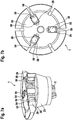
- Fig. 7 shows a further embodiment of the control valve 1, only the essential areas being shown.
- the crown ring 20 of the execution of the Fig.7a / Fig.7b advantageously has three crowns 29, in principle any number of crowns 29 can be used.
- the anchor plate 50 has a corresponding number of plate grooves 54, 55, 56 through which the crowns 29 are guided in the axial direction.
- the crowns 29 cooperate on the end face with the magnet assembly 2, not shown, or are braced with the latter.
- a bearing recess 59 is formed in each of the crowns 29.
- the bearing recesses 59 are designed in the form of a clamp, in such a way that they are open in the circumferential direction of the crown ring 20 and to the magnet assembly 2.
- the bearing recesses 59 serve to receive rolling elements 58, which are preferably spherical; As a result, the bearing recesses 59 perform the function of bearing cages.
- the rolling elements 58 are dimensioned and positioned in the bearing recesses 59 in such a way that they interact with the plate grooves 54, 55, 56 of the anchor plate 50, specifically in both circumferential directions, that is to say tangentially, so that each rolling element 58 can transmit rotational forces in both directions.
- the armature 5 is therefore guided almost smoothly by the rolling elements 58.
- the anti-rotation device of the anchor plate 50 or of the armature 5 is thus designed to be very low-friction and low-wear, since the armature 5 rolls on the rolling elements 58 virtually over its plate grooves 54, 55, 56.
- the rolling elements 58 are preferably made of an amagnetic material, for example a ceramic, so that they are not influenced by the electromagnetic forces of the magnet assembly 2.
- the Fig. 8 shows one to Fig. 7 alternative rotation lock of the anchor plate 50.
- the bearing recesses 59 are in the embodiment of the Fig. 8 Pot-shaped, each with an open end in the circumferential direction of the armature 5.
- a rolling element 58 is positioned in each case in a bearing recess 59 such that it cooperates with a flank of the corresponding plate groove 54, 55, 56 at the open end of the bearing recess 59.
- the anchor plate 50 is supported on a plate groove 54, 55, 56 in a circumferential direction, but not in the opposite oriented circumferential direction. Therefore, at least one further rolling element 58 is required, which also supports the armature plate 50 in the opposite oriented circumferential direction.
- the crown ring preferably has a different shape than in FIGS Fig.8a / Fig.8b shown, an even number of crowns 29, so that the rolling elements 58 arranged in the associated bearing recesses 59 each support the anchor plate 50 in pairs in both circumferential directions.
- the rolling elements 58 are supported by the crowns 29 in the radial direction.
- the radial direction to the outside can also be supported by a further component, for example by the residual air gap disk 23, if this, as in the exemplary embodiment in FIG Fig. 6 is arranged.
- the mode of operation of the fuel injector 100 according to the invention is as follows: The injections via the injection openings 13 into the combustion chamber of the internal combustion engine are caused by the longitudinal movement of the or multi-part injection valve member 11, the longitudinal movements of which are in turn controlled by the control valve 1, the control valve 1 being controlled by the magnet assembly 2.
- the injection valve member 11 is guided in the valve piece 4 at its end opposite the injection openings 13 and delimits the control chamber 15 there.
- the magnet assembly 2 When the magnetic core 3 is energized, the magnet assembly 2 exerts an attractive force on the armature 5 and moves it away from the valve seat 7 against the force of the spring 8. The hydraulic connection from the valve chamber 17 to the low-pressure chamber 18 is thereby opened and the control chamber 15 is consequently relieved. The hydraulically closing force in the control chamber 15 on the injection valve member 11 in the direction of the injection openings 13 is reduced and the injection valve member 11 releases the injection openings 13 so that the fuel injector 100 injects into the combustion chamber of the internal combustion engine.
- the components of the control valve 1 that have an influence on the stroke of the armature 5 are reduced: the axial distance between the valve seat 7 and the magnet assembly 2 is defined by the valve piece 4, crown ring 20 and optionally armature stroke adjusting disk 21. If the effective length of the armature 5 and, if appropriate, the height of the residual air gap disk 23 are subtracted from this, the maximum possible armature stroke is obtained.
- the pressure and temperature dependency of the anchor stroke is reduced; the two components determining the axial length are the armature 5 and the crown ring 20.
- the armature 5 heats up dynamically faster than the crown ring 20.
- the material of the crown ring 20 is selected such that it has a greater coefficient of thermal expansion than the material of the armature 5 Coefficient of thermal expansion of the crown ring 20 can be compensated.
- the material of the crown ring 20 is advantageously selected such that it does not impair the magnetic flux of the magnetic assembly 2, for example made of austenitic steel or a ceramic.
- the crowns 29 of the crown ring 20 protruding through the anchor plate 50 also have a function for securing the anchor plate 50 or the anchor 5 against rotation.
- the use of rolling elements 58 makes this rotation lock particularly low-friction.
Landscapes
- Engineering & Computer Science (AREA)
- Chemical & Material Sciences (AREA)
- Combustion & Propulsion (AREA)
- Mechanical Engineering (AREA)
- General Engineering & Computer Science (AREA)
- Physics & Mathematics (AREA)
- Fluid Mechanics (AREA)
- Fuel-Injection Apparatus (AREA)
Claims (13)
- Injecteur de carburant (100) pour l'injection de carburant dans la chambre de combustion d'un moteur à combustion interne, l'injecteur de carburant (100) comprenant une soupape de commande (1) et un organe de soupape d'injection (11), l'organe de soupape d'injection (11) délimitant un espace de commande (15) et étant guidé de manière déplaçable longitudinalement dans l'injecteur de carburant (11) et ouvrant et fermant, par son déplacement, au moins une ouverture d'injection (13) dans la chambre de combustion, la soupape de commande (1) contrôlant la pression dans l'espace de commande (15), la soupape de commande (1) comprenant un module magnétique (2), un induit (5), une pièce de soupape (4) et un siège de soupape (7) réalisé au niveau de la pièce de soupape (4), l'induit (5) comprenant une plaque d'induit (50), la plaque d'induit (50) pouvant être commandée par le module magnétique (2), l'induit (5) coopérant au moins indirectement avec le siège de soupape (7) pour décharger l'espace de commande (15), une bague formant couronne (20) étant serrée entre la pièce de soupape (4) et le module magnétique (2),
caractérisé en ce que dans la plaque d'induit (50) est réalisée une rainure de plaque (54) et en ce que la bague formant couronne (20) présente une couronne (29), la couronne (29) faisant saillie à travers la rainure de plaque (54). - Injecteur de carburant (100) selon la revendication 1, caractérisé en ce qu'un logement de palier (59) est réalisé dans la couronne (29), un corps de roulement (58) étant supporté dans le logement de palier (59), le corps de roulement (58) coopérant avec la rainure de plaque (54).
- Injecteur de carburant (100) pour l'injection de carburant dans la chambre de combustion d'un moteur à combustion interne, l'injecteur de carburant (100) comprenant une soupape de commande (1) et un organe de soupape d'injection (11), l'organe de soupape d'injection (11) délimitant un espace de commande (15) et étant guidé de manière déplaçable longitudinalement dans l'injecteur de carburant (11) et ouvrant et fermant, par son déplacement, au moins une ouverture d'injection (13) dans la chambre de combustion, la soupape de commande (1) contrôlant la pression dans l'espace de commande (15), la soupape de commande (1) comprenant un module magnétique (2), un induit (5), une pièce de soupape (4) et un siège de soupape (7) réalisé au niveau de la pièce de soupape (4), l'induit (5) comprenant une plaque d'induit (50), la plaque d'induit (50) pouvant être commandée par le module magnétique (2), l'induit (5) coopérant au moins indirectement avec le siège de soupape (7) pour décharger l'espace de commande (15), une bague formant couronne (20) étant serrée entre la pièce de soupape (4) et le module magnétique (2), la bague formant couronne (20) entourant l'induit (5) à l'extérieur, caractérisé en ce que
le matériau de la bague formant couronne (29) présente un coefficient de dilatation thermique supérieur à celui du matériau de l'induit (5). - Injecteur de carburant (100) selon l'une quelconque des revendications 1 à 3, caractérisé en ce qu'une surface d'enveloppe cylindrique (43) est réalisée au niveau de la pièce de soupape (4), la bague formant couronne (20) étant positionnée sur la surface d'enveloppe (43) coaxialement au siège de soupape (7).
- Injecteur de carburant (100) selon l'une quelconque des revendications 1 à 4, caractérisé en ce qu'une surface de guidage cylindrique (28) est réalisée au niveau de la bague formant couronne (20), l'induit (5) étant guidé de manière déplaçable longitudinalement dans la surface de guidage (28).
- Injecteur de carburant (100) selon l'une quelconque des revendications 1 à 5, caractérisé en ce qu'un disque d'ajustement de la course d'induit (21) est serré entre la bague formant couronne (20) et la pièce de soupape (4).
- Injecteur de carburant (100) selon l'une quelconque des revendications 1 à 5, caractérisé en ce qu'un disque d'ajustement de la course d'induit (21) est serré entre la bague formant couronne (20) et le module magnétique (2).
- Injecteur de carburant (100) selon l'une quelconque des revendications 1 à 7, caractérisé en ce qu'entre le module magnétique (2) et la plaque d'induit (50) est disposé un disque d'entrefer résiduel (23).
- Injecteur de carburant (100) selon l'une quelconque des revendications 1 à 8, caractérisé en ce que le matériau de la bague formant couronne (29) est amagnétique, de préférence est un acier fritté austénitique ou une céramique.
- Injecteur de carburant (100) selon l'une quelconque des revendications 1 à 9, caractérisé en ce que le module magnétique (2) est serré au moyen d'un ressort de serrage (22) avec la bague formant couronne (20).
- Injecteur de carburant (100) selon l'une quelconque des revendications 1 à 10, caractérisé en ce que le module magnétique (2) peut être mis en contact électrique avec au moins une goupille de contact (31) et en ce que l'au moins une goupille de contact (31) présente un siège de coulisseau (31a).
- Injecteur de carburant (100) selon l'une quelconque des revendications 1 à 11, caractérisé en ce que l'induit (5) est sollicité par un ressort (8) dans la direction du siège de soupape (7) .
- Injecteur de carburant (100) selon l'une quelconque des revendications 1 à 12, caractérisé en ce qu'un boulon d'induit (6) fait saillie à travers l'induit (5).
Applications Claiming Priority (2)
| Application Number | Priority Date | Filing Date | Title |
|---|---|---|---|
| DE102015224177.7A DE102015224177A1 (de) | 2015-12-03 | 2015-12-03 | Kraftstoffinjektor mit Steuerventil |
| PCT/EP2016/076439 WO2017092955A1 (fr) | 2015-12-03 | 2016-11-02 | Injecteur de carburant muni d'une soupape de commande |
Publications (2)
| Publication Number | Publication Date |
|---|---|
| EP3384149A1 EP3384149A1 (fr) | 2018-10-10 |
| EP3384149B1 true EP3384149B1 (fr) | 2020-05-06 |
Family
ID=57218920
Family Applications (1)
| Application Number | Title | Priority Date | Filing Date |
|---|---|---|---|
| EP16788726.4A Active EP3384149B1 (fr) | 2015-12-03 | 2016-11-02 | Injecteur de carburant muni d'une soupape de commande |
Country Status (5)
| Country | Link |
|---|---|
| EP (1) | EP3384149B1 (fr) |
| KR (1) | KR102623972B1 (fr) |
| CN (1) | CN108291509B (fr) |
| DE (1) | DE102015224177A1 (fr) |
| WO (1) | WO2017092955A1 (fr) |
Families Citing this family (2)
| Publication number | Priority date | Publication date | Assignee | Title |
|---|---|---|---|---|
| DE102016225948A1 (de) | 2016-12-22 | 2018-06-28 | Robert Bosch Gmbh | Kraftstoffinjektor |
| CN111894776B (zh) * | 2020-07-06 | 2021-09-17 | 一汽解放汽车有限公司 | 一种燃料喷射器 |
Family Cites Families (14)
| Publication number | Priority date | Publication date | Assignee | Title |
|---|---|---|---|---|
| DE4013832A1 (de) * | 1990-04-30 | 1991-10-31 | Bosch Gmbh Robert | Elektromagnetisch betaetigbares brennstoffeinspritzventil |
| DE19650865A1 (de) | 1996-12-07 | 1998-06-10 | Bosch Gmbh Robert | Magnetventil |
| DE10131201A1 (de) * | 2001-06-28 | 2003-01-16 | Bosch Gmbh Robert | Magnetventil zur Steuerung eines Einspritzventils einer Brennkraftmaschine |
| DE10240880B4 (de) * | 2002-09-04 | 2016-12-01 | Robert Bosch Gmbh | Aktorverbindung an Kraftstoffinjektoren von Verbrennungskraftmaschinen |
| US20060138374A1 (en) * | 2004-04-14 | 2006-06-29 | Lucas Michael A | Solenoid actuated flow control valve including adjustable spacer |
| JP2006257874A (ja) * | 2004-04-30 | 2006-09-28 | Denso Corp | インジェクタ |
| ATE352714T1 (de) * | 2005-06-17 | 2007-02-15 | Magneti Marelli Powertrain Spa | Brennstoffeinspritzventil |
| DE102007025614A1 (de) * | 2007-06-01 | 2008-12-04 | Robert Bosch Gmbh | Ankerhubeinstellung für Magnetventil |
| DE102007025961A1 (de) * | 2007-06-04 | 2008-12-11 | Robert Bosch Gmbh | Injektor |
| DE102008005532A1 (de) * | 2008-01-22 | 2009-07-23 | Robert Bosch Gmbh | Kraftstoffinjektor, dessen Steuerventilelement einen Stützbereich aufweist |
| US8689772B2 (en) * | 2011-05-19 | 2014-04-08 | Caterpillar Inc. | Fuel injector with telescoping armature overtravel feature |
| JP5689395B2 (ja) * | 2011-09-28 | 2015-03-25 | ナブテスコ株式会社 | 電磁弁 |
| EP2713040B1 (fr) * | 2012-09-26 | 2017-06-07 | Delphi International Operations Luxembourg S.à r.l. | Connecteur électrique |
| GB201503158D0 (en) * | 2015-02-25 | 2015-04-08 | Delphi International Operations Luxembourg S.�.R.L. | Control valve arrangement |
-
2015
- 2015-12-03 DE DE102015224177.7A patent/DE102015224177A1/de not_active Withdrawn
-
2016
- 2016-11-02 WO PCT/EP2016/076439 patent/WO2017092955A1/fr not_active Ceased
- 2016-11-02 KR KR1020187018585A patent/KR102623972B1/ko active Active
- 2016-11-02 CN CN201680070780.4A patent/CN108291509B/zh active Active
- 2016-11-02 EP EP16788726.4A patent/EP3384149B1/fr active Active
Non-Patent Citations (1)
| Title |
|---|
| None * |
Also Published As
| Publication number | Publication date |
|---|---|
| CN108291509A (zh) | 2018-07-17 |
| KR102623972B1 (ko) | 2024-01-11 |
| DE102015224177A1 (de) | 2017-06-08 |
| KR20180090842A (ko) | 2018-08-13 |
| CN108291509B (zh) | 2020-12-04 |
| WO2017092955A1 (fr) | 2017-06-08 |
| EP3384149A1 (fr) | 2018-10-10 |
Similar Documents
| Publication | Publication Date | Title |
|---|---|---|
| EP2021617B1 (fr) | Injecteur de carburant comportant une soupape de commande à compensation de pression | |
| EP2283226B1 (fr) | Injecteur de carburant pour moteurs a combustion interne | |
| EP1266135B1 (fr) | Electrovanne destinee a commander la soupape d'injection d'un moteur a combustion interne | |
| EP1831537B1 (fr) | Injecteur de systeme d'injection de carburant d'un moteur a combustion interne | |
| EP2867517B1 (fr) | Injecteur de carburant pour moteurs à combustion interne | |
| EP2092187B1 (fr) | Injecteur pour l'injection de carburant | |
| EP3535486B1 (fr) | Soupape d'injection de carburant pour injecter un carburant gazeux et / ou liquide | |
| EP2102486B1 (fr) | Injecteur avec une soupape de commande à compensation de pression axiale | |
| EP2715103B1 (fr) | Ensemble buse pour un injecteur de carburant et injecteur de carburant | |
| DE102008002717A1 (de) | Kraftstoffinjektor mit zweiteiligem Magnetanker | |
| EP1948922B1 (fr) | Guidage optimise de groupes d'induits pour soupapes magnetiques | |
| EP2454467B1 (fr) | Système de soupape | |
| WO2011095367A1 (fr) | Ensemble soupape de commande d'un injecteur de carburant | |
| EP1967726B1 (fr) | Injecteur à soupape magnétique | |
| EP3384149B1 (fr) | Injecteur de carburant muni d'une soupape de commande | |
| EP2025922B1 (fr) | Soupape d'injection de carburant pour moteurs à combustion interne | |
| EP1999363B1 (fr) | Soupapes d'injection de carburant pour moteurs a combustion interne | |
| EP2957760B1 (fr) | Ensemble de buses pour un injecteur de carburant et injecteur de carburant | |
| DE19963926A1 (de) | Steuerventil für eine Kraftstoffeinspritzvorrichtung für Brennkraftmaschinen mit verstellbarem Hubanschlag | |
| EP2653712A1 (fr) | Injecteur de carburant avec électrovanne | |
| WO2015106934A1 (fr) | Injecteur de carburant | |
| EP2016276B1 (fr) | Injecteur de carburant avec un circuit de reflux optimise | |
| WO2009021864A1 (fr) | Soupape pilote pour injecteur de carburant | |
| EP3035520B1 (fr) | Unité de couplage hydraulique destinée à commander une soupape | |
| EP3423717B1 (fr) | Soupape d'admission à commande électromagnétique et pompe haute pression munie d'une soupape d'admission |
Legal Events
| Date | Code | Title | Description |
|---|---|---|---|
| STAA | Information on the status of an ep patent application or granted ep patent |
Free format text: STATUS: UNKNOWN |
|
| STAA | Information on the status of an ep patent application or granted ep patent |
Free format text: STATUS: THE INTERNATIONAL PUBLICATION HAS BEEN MADE |
|
| PUAI | Public reference made under article 153(3) epc to a published international application that has entered the european phase |
Free format text: ORIGINAL CODE: 0009012 |
|
| STAA | Information on the status of an ep patent application or granted ep patent |
Free format text: STATUS: REQUEST FOR EXAMINATION WAS MADE |
|
| 17P | Request for examination filed |
Effective date: 20180703 |
|
| AK | Designated contracting states |
Kind code of ref document: A1 Designated state(s): AL AT BE BG CH CY CZ DE DK EE ES FI FR GB GR HR HU IE IS IT LI LT LU LV MC MK MT NL NO PL PT RO RS SE SI SK SM TR |
|
| AX | Request for extension of the european patent |
Extension state: BA ME |
|
| DAV | Request for validation of the european patent (deleted) | ||
| DAX | Request for extension of the european patent (deleted) | ||
| GRAP | Despatch of communication of intention to grant a patent |
Free format text: ORIGINAL CODE: EPIDOSNIGR1 |
|
| STAA | Information on the status of an ep patent application or granted ep patent |
Free format text: STATUS: GRANT OF PATENT IS INTENDED |
|
| INTG | Intention to grant announced |
Effective date: 20200115 |
|
| GRAS | Grant fee paid |
Free format text: ORIGINAL CODE: EPIDOSNIGR3 |
|
| GRAA | (expected) grant |
Free format text: ORIGINAL CODE: 0009210 |
|
| STAA | Information on the status of an ep patent application or granted ep patent |
Free format text: STATUS: THE PATENT HAS BEEN GRANTED |
|
| RAP1 | Party data changed (applicant data changed or rights of an application transferred) |
Owner name: ROBERT BOSCH GMBH |
|
| AK | Designated contracting states |
Kind code of ref document: B1 Designated state(s): AL AT BE BG CH CY CZ DE DK EE ES FI FR GB GR HR HU IE IS IT LI LT LU LV MC MK MT NL NO PL PT RO RS SE SI SK SM TR |
|
| REG | Reference to a national code |
Ref country code: GB Ref legal event code: FG4D Free format text: NOT ENGLISH |
|
| REG | Reference to a national code |
Ref country code: CH Ref legal event code: EP Ref country code: AT Ref legal event code: REF Ref document number: 1267138 Country of ref document: AT Kind code of ref document: T Effective date: 20200515 |
|
| REG | Reference to a national code |
Ref country code: DE Ref legal event code: R096 Ref document number: 502016009889 Country of ref document: DE |
|
| REG | Reference to a national code |
Ref country code: IE Ref legal event code: FG4D Free format text: LANGUAGE OF EP DOCUMENT: GERMAN |
|
| REG | Reference to a national code |
Ref country code: LT Ref legal event code: MG4D |
|
| REG | Reference to a national code |
Ref country code: NL Ref legal event code: MP Effective date: 20200506 |
|
| PG25 | Lapsed in a contracting state [announced via postgrant information from national office to epo] |
Ref country code: NO Free format text: LAPSE BECAUSE OF FAILURE TO SUBMIT A TRANSLATION OF THE DESCRIPTION OR TO PAY THE FEE WITHIN THE PRESCRIBED TIME-LIMIT Effective date: 20200806 Ref country code: FI Free format text: LAPSE BECAUSE OF FAILURE TO SUBMIT A TRANSLATION OF THE DESCRIPTION OR TO PAY THE FEE WITHIN THE PRESCRIBED TIME-LIMIT Effective date: 20200506 Ref country code: GR Free format text: LAPSE BECAUSE OF FAILURE TO SUBMIT A TRANSLATION OF THE DESCRIPTION OR TO PAY THE FEE WITHIN THE PRESCRIBED TIME-LIMIT Effective date: 20200807 Ref country code: SE Free format text: LAPSE BECAUSE OF FAILURE TO SUBMIT A TRANSLATION OF THE DESCRIPTION OR TO PAY THE FEE WITHIN THE PRESCRIBED TIME-LIMIT Effective date: 20200506 Ref country code: IS Free format text: LAPSE BECAUSE OF FAILURE TO SUBMIT A TRANSLATION OF THE DESCRIPTION OR TO PAY THE FEE WITHIN THE PRESCRIBED TIME-LIMIT Effective date: 20200906 Ref country code: PT Free format text: LAPSE BECAUSE OF FAILURE TO SUBMIT A TRANSLATION OF THE DESCRIPTION OR TO PAY THE FEE WITHIN THE PRESCRIBED TIME-LIMIT Effective date: 20200907 Ref country code: LT Free format text: LAPSE BECAUSE OF FAILURE TO SUBMIT A TRANSLATION OF THE DESCRIPTION OR TO PAY THE FEE WITHIN THE PRESCRIBED TIME-LIMIT Effective date: 20200506 |
|
| PG25 | Lapsed in a contracting state [announced via postgrant information from national office to epo] |
Ref country code: LV Free format text: LAPSE BECAUSE OF FAILURE TO SUBMIT A TRANSLATION OF THE DESCRIPTION OR TO PAY THE FEE WITHIN THE PRESCRIBED TIME-LIMIT Effective date: 20200506 Ref country code: HR Free format text: LAPSE BECAUSE OF FAILURE TO SUBMIT A TRANSLATION OF THE DESCRIPTION OR TO PAY THE FEE WITHIN THE PRESCRIBED TIME-LIMIT Effective date: 20200506 Ref country code: RS Free format text: LAPSE BECAUSE OF FAILURE TO SUBMIT A TRANSLATION OF THE DESCRIPTION OR TO PAY THE FEE WITHIN THE PRESCRIBED TIME-LIMIT Effective date: 20200506 Ref country code: BG Free format text: LAPSE BECAUSE OF FAILURE TO SUBMIT A TRANSLATION OF THE DESCRIPTION OR TO PAY THE FEE WITHIN THE PRESCRIBED TIME-LIMIT Effective date: 20200806 |
|
| PG25 | Lapsed in a contracting state [announced via postgrant information from national office to epo] |
Ref country code: NL Free format text: LAPSE BECAUSE OF FAILURE TO SUBMIT A TRANSLATION OF THE DESCRIPTION OR TO PAY THE FEE WITHIN THE PRESCRIBED TIME-LIMIT Effective date: 20200506 Ref country code: AL Free format text: LAPSE BECAUSE OF FAILURE TO SUBMIT A TRANSLATION OF THE DESCRIPTION OR TO PAY THE FEE WITHIN THE PRESCRIBED TIME-LIMIT Effective date: 20200506 |
|
| PG25 | Lapsed in a contracting state [announced via postgrant information from national office to epo] |
Ref country code: IT Free format text: LAPSE BECAUSE OF FAILURE TO SUBMIT A TRANSLATION OF THE DESCRIPTION OR TO PAY THE FEE WITHIN THE PRESCRIBED TIME-LIMIT Effective date: 20200506 Ref country code: RO Free format text: LAPSE BECAUSE OF FAILURE TO SUBMIT A TRANSLATION OF THE DESCRIPTION OR TO PAY THE FEE WITHIN THE PRESCRIBED TIME-LIMIT Effective date: 20200506 Ref country code: DK Free format text: LAPSE BECAUSE OF FAILURE TO SUBMIT A TRANSLATION OF THE DESCRIPTION OR TO PAY THE FEE WITHIN THE PRESCRIBED TIME-LIMIT Effective date: 20200506 Ref country code: SM Free format text: LAPSE BECAUSE OF FAILURE TO SUBMIT A TRANSLATION OF THE DESCRIPTION OR TO PAY THE FEE WITHIN THE PRESCRIBED TIME-LIMIT Effective date: 20200506 Ref country code: EE Free format text: LAPSE BECAUSE OF FAILURE TO SUBMIT A TRANSLATION OF THE DESCRIPTION OR TO PAY THE FEE WITHIN THE PRESCRIBED TIME-LIMIT Effective date: 20200506 Ref country code: ES Free format text: LAPSE BECAUSE OF FAILURE TO SUBMIT A TRANSLATION OF THE DESCRIPTION OR TO PAY THE FEE WITHIN THE PRESCRIBED TIME-LIMIT Effective date: 20200506 Ref country code: CZ Free format text: LAPSE BECAUSE OF FAILURE TO SUBMIT A TRANSLATION OF THE DESCRIPTION OR TO PAY THE FEE WITHIN THE PRESCRIBED TIME-LIMIT Effective date: 20200506 |
|
| REG | Reference to a national code |
Ref country code: DE Ref legal event code: R097 Ref document number: 502016009889 Country of ref document: DE |
|
| PG25 | Lapsed in a contracting state [announced via postgrant information from national office to epo] |
Ref country code: SK Free format text: LAPSE BECAUSE OF FAILURE TO SUBMIT A TRANSLATION OF THE DESCRIPTION OR TO PAY THE FEE WITHIN THE PRESCRIBED TIME-LIMIT Effective date: 20200506 Ref country code: PL Free format text: LAPSE BECAUSE OF FAILURE TO SUBMIT A TRANSLATION OF THE DESCRIPTION OR TO PAY THE FEE WITHIN THE PRESCRIBED TIME-LIMIT Effective date: 20200506 |
|
| PLBE | No opposition filed within time limit |
Free format text: ORIGINAL CODE: 0009261 |
|
| STAA | Information on the status of an ep patent application or granted ep patent |
Free format text: STATUS: NO OPPOSITION FILED WITHIN TIME LIMIT |
|
| 26N | No opposition filed |
Effective date: 20210209 |
|
| PG25 | Lapsed in a contracting state [announced via postgrant information from national office to epo] |
Ref country code: SI Free format text: LAPSE BECAUSE OF FAILURE TO SUBMIT A TRANSLATION OF THE DESCRIPTION OR TO PAY THE FEE WITHIN THE PRESCRIBED TIME-LIMIT Effective date: 20200506 |
|
| PG25 | Lapsed in a contracting state [announced via postgrant information from national office to epo] |
Ref country code: MC Free format text: LAPSE BECAUSE OF FAILURE TO SUBMIT A TRANSLATION OF THE DESCRIPTION OR TO PAY THE FEE WITHIN THE PRESCRIBED TIME-LIMIT Effective date: 20200506 |
|
| REG | Reference to a national code |
Ref country code: CH Ref legal event code: PL |
|
| GBPC | Gb: european patent ceased through non-payment of renewal fee |
Effective date: 20201102 |
|
| PG25 | Lapsed in a contracting state [announced via postgrant information from national office to epo] |
Ref country code: LU Free format text: LAPSE BECAUSE OF NON-PAYMENT OF DUE FEES Effective date: 20201102 |
|
| REG | Reference to a national code |
Ref country code: BE Ref legal event code: MM Effective date: 20201130 |
|
| PG25 | Lapsed in a contracting state [announced via postgrant information from national office to epo] |
Ref country code: CH Free format text: LAPSE BECAUSE OF NON-PAYMENT OF DUE FEES Effective date: 20201130 Ref country code: LI Free format text: LAPSE BECAUSE OF NON-PAYMENT OF DUE FEES Effective date: 20201130 |
|
| PG25 | Lapsed in a contracting state [announced via postgrant information from national office to epo] |
Ref country code: FR Free format text: LAPSE BECAUSE OF NON-PAYMENT OF DUE FEES Effective date: 20201130 Ref country code: IE Free format text: LAPSE BECAUSE OF NON-PAYMENT OF DUE FEES Effective date: 20201102 |
|
| PG25 | Lapsed in a contracting state [announced via postgrant information from national office to epo] |
Ref country code: GB Free format text: LAPSE BECAUSE OF NON-PAYMENT OF DUE FEES Effective date: 20201102 |
|
| PG25 | Lapsed in a contracting state [announced via postgrant information from national office to epo] |
Ref country code: TR Free format text: LAPSE BECAUSE OF FAILURE TO SUBMIT A TRANSLATION OF THE DESCRIPTION OR TO PAY THE FEE WITHIN THE PRESCRIBED TIME-LIMIT Effective date: 20200506 Ref country code: MT Free format text: LAPSE BECAUSE OF FAILURE TO SUBMIT A TRANSLATION OF THE DESCRIPTION OR TO PAY THE FEE WITHIN THE PRESCRIBED TIME-LIMIT Effective date: 20200506 Ref country code: CY Free format text: LAPSE BECAUSE OF FAILURE TO SUBMIT A TRANSLATION OF THE DESCRIPTION OR TO PAY THE FEE WITHIN THE PRESCRIBED TIME-LIMIT Effective date: 20200506 |
|
| PG25 | Lapsed in a contracting state [announced via postgrant information from national office to epo] |
Ref country code: MK Free format text: LAPSE BECAUSE OF FAILURE TO SUBMIT A TRANSLATION OF THE DESCRIPTION OR TO PAY THE FEE WITHIN THE PRESCRIBED TIME-LIMIT Effective date: 20200506 |
|
| PG25 | Lapsed in a contracting state [announced via postgrant information from national office to epo] |
Ref country code: BE Free format text: LAPSE BECAUSE OF NON-PAYMENT OF DUE FEES Effective date: 20201130 |
|
| REG | Reference to a national code |
Ref country code: AT Ref legal event code: MM01 Ref document number: 1267138 Country of ref document: AT Kind code of ref document: T Effective date: 20211102 |
|
| PG25 | Lapsed in a contracting state [announced via postgrant information from national office to epo] |
Ref country code: AT Free format text: LAPSE BECAUSE OF NON-PAYMENT OF DUE FEES Effective date: 20211102 |
|
| PG25 | Lapsed in a contracting state [announced via postgrant information from national office to epo] |
Ref country code: IS Free format text: LAPSE BECAUSE OF NON-PAYMENT OF DUE FEES Effective date: 20200906 |
|
| PGFP | Annual fee paid to national office [announced via postgrant information from national office to epo] |
Ref country code: DE Payment date: 20260126 Year of fee payment: 10 |