EP3392013A1 - Injektor, vorderteil für einen injektor, verfahren und produktionsanlage zur herstellung von formteilen aus kunststoff - Google Patents
Injektor, vorderteil für einen injektor, verfahren und produktionsanlage zur herstellung von formteilen aus kunststoff Download PDFInfo
- Publication number
- EP3392013A1 EP3392013A1 EP17167454.2A EP17167454A EP3392013A1 EP 3392013 A1 EP3392013 A1 EP 3392013A1 EP 17167454 A EP17167454 A EP 17167454A EP 3392013 A1 EP3392013 A1 EP 3392013A1
- Authority
- EP
- European Patent Office
- Prior art keywords
- front part
- injector
- longitudinal axis
- drive
- parts
- Prior art date
- Legal status (The legal status is an assumption and is not a legal conclusion. Google has not performed a legal analysis and makes no representation as to the accuracy of the status listed.)
- Granted
Links
Images


Classifications
-
- B—PERFORMING OPERATIONS; TRANSPORTING
- B29—WORKING OF PLASTICS; WORKING OF SUBSTANCES IN A PLASTIC STATE IN GENERAL
- B29C—SHAPING OR JOINING OF PLASTICS; SHAPING OF MATERIAL IN A PLASTIC STATE, NOT OTHERWISE PROVIDED FOR; AFTER-TREATMENT OF THE SHAPED PRODUCTS, e.g. REPAIRING
- B29C44/00—Shaping by internal pressure generated in the material, e.g. swelling or foaming ; Producing porous or cellular expanded plastics articles
- B29C44/34—Auxiliary operations
- B29C44/36—Feeding the material to be shaped
- B29C44/38—Feeding the material to be shaped into a closed space, i.e. to make articles of definite length
- B29C44/44—Feeding the material to be shaped into a closed space, i.e. to make articles of definite length in solid form
- B29C44/445—Feeding the material to be shaped into a closed space, i.e. to make articles of definite length in solid form in the form of expandable granules, particles or beads
-
- B—PERFORMING OPERATIONS; TRANSPORTING
- B29—WORKING OF PLASTICS; WORKING OF SUBSTANCES IN A PLASTIC STATE IN GENERAL
- B29C—SHAPING OR JOINING OF PLASTICS; SHAPING OF MATERIAL IN A PLASTIC STATE, NOT OTHERWISE PROVIDED FOR; AFTER-TREATMENT OF THE SHAPED PRODUCTS, e.g. REPAIRING
- B29C31/00—Handling, e.g. feeding of the material to be shaped, storage of plastics material before moulding; Automation, i.e. automated handling lines in plastics processing plants, e.g. using manipulators or robots
- B29C31/04—Feeding of the material to be moulded, e.g. into a mould cavity
- B29C31/041—Feeding of the material to be moulded, e.g. into a mould cavity using filling or dispensing heads placed in closed moulds or in contact with mould walls
Definitions
- the invention relates to an injector for filling a mold with plastic particles according to the preamble of claim 1.
- the invention relates to a front part for an injector for filling a mold with plastic particles according to the preamble of claim 8.
- the invention also relates to a method and a production plant for the production molded plastic parts in a number of forms.
- mold changes i. if the foaming machine is to be converted from one to another molding, injectors are introduced by the plastic particles with compressed air into a mold in which the plastic is foamed, disassembled from the mold and mounted on the subsequent mold.
- This step costs time and thus money. Since the conversion is usually expensive, the production stands still for a period of time, which increases the partial costs.
- the molds can all be equipped with their own injectors, which minimizes makeready times, but drives up investment costs enormously.
- set-up processes play an increasingly important role.
- injectors In addition to retooling when changing tools, in the current production process injectors have to be cleaned under unfavorable conditions inside, since during the filling process the plastic can become clogged and welded in the injectors themselves. Also, a complex disassembly of the injectors of the form is necessary.
- Split-type injectors can be used to speed up changeover and cleaning and keep costs under control. These form a compromise between investment and set-up costs.
- the previously offered on the market versions can only be complicated and share with the help of additional tools.
- the patent application DE 10 2009 024 278 A1 discloses a divisible injector in which a pipe, for example by a screw connection with a union nut, releasably connected to a connector.
- a disadvantage of a screw is that it must be tightened with a defined torque, on the one hand to ensure that the connection is not solved by the pressure prevailing in the injector in the overpressure, which is typically in the range of 6 to 8 bar, and on the other hand Damage to the injector due to over tightening.
- special tools and trained personnel are necessary, whereby the assembly and disassembly of the injector are expensive and expensive.
- the patent application DE 10 2013 114 170 A1 describes an injector with a front part and a base part, which can be connected via a plug connection with corresponding half-ring grooves and this sweeping plug or dowel pins.
- the parts may also be connected by threaded bolts.
- the disadvantage of this is that the pins are not connected to the injector, so they can easily be lost during assembly or disassembly.
- the parts must be made with a low tolerance so that a connector can ensure the necessary tightness and stability against the prevailing in operation in the injector pressure. Therefore, the production of the described injector is complicated and expensive. Furthermore, it is also not possible here to correct the orientation of the base part after the connection.
- An inventive injector for filling a mold with plastic particles comprises a particularly tubular and / or inventive, front part with a mouth end for connection to the mold and a drive part for arrangement at a muzzle end opposite the connecting end of the front part.
- the drive part comprises a piston insertable into the front part and a drive for moving the piston along a longitudinal axis of the front part.
- the piston can be moved by the drive into a filling position and a closing position. In the closed position, the piston closes a filling opening of the mold to which the injector is connected, for example, to prevent leakage of plastic during foaming of the plastic.
- plastic particles may be present, for example, as a powder or granules.
- the plastic particles and / or each individual plastic particle may in particular consist of exactly one plastic or of a mixture of several plastics.
- Such a plastic is preferably foamable, such as expandable polystyrene, polypropylene or polyethylene.
- the injector comprises a connecting device for releasably fixing the drive part in preferably at least radial and axial direction with respect to the longitudinal axis on the front part, wherein the drive part can be mounted rotatably about the longitudinal axis on the front part.
- a fixation in the radial and axial direction ensures that the parts are reliably held together during operation of the injector, so that the risk of accidents, malfunctions and / or damage caused by a loosening drive part and / or uncontrolled escaping compressed air and / or plastic particles is minimized.
- a radial fixation can for example be achieved in a simple manner by the front part, the connecting device and the drive part in the radial direction positively connected, in particular inserted into each other, are.
- the connecting device may be attached to the drive part.
- the connecting device can be transferred together with the drive part in a simple manner from a front part to another front part.
- the front part can be constructed particularly simple. This is particularly advantageous if the front part is to remain in a conversion process to save time on the mold. In this case, considerable savings can be made by a simply constructed front part.
- the connecting device may be fastened to the drive part, for example, by a screw or clamp connection or a material connection.
- the drive part may have an internal thread, into which a corresponding external thread of the connecting device is screwed in and advantageously secured with thread locking adhesive.
- thread locking adhesive a thread that is screwed in and advantageously secured with thread locking adhesive.
- a screw connection has the advantage that differently designed connection devices and / or drive parts can be modularly combined with one another and securely fastened to one another.
- connection device may comprise a number of connectors for fixing the connection device to the drive part or to the front part in the axial direction with respect to the longitudinal axis.
- the connectors can, for example, comprise spring elements which, in particular, as in the case of a plug-in buckle or a plug-in lock, resiliently engage in spring element receptacles in order to produce a non-positive connection of the connecting device with the front part or the drive part in the axial direction.
- the connectors may be configured to cooperate with a number of mating connectors on the front part or the drive part with respect to a movement along the longitudinal axis in a form-fitting manner.
- connectors and counter connectors in a longitudinal axis comprehensive cutting plane complementary forms. This allows you to interact in a particularly reliable form-locking manner in the axial direction.
- the connectors may be formed as radial projections and the counter connectors as radial recesses or vice versa.
- a radial recess is configured as a groove running around the longitudinal axis, since connectors or counter-connectors engaging in the groove can thus be fixed with respect to rotation about the longitudinal axis in a movable manner and at the same time in the axial and radial directions. Furthermore, a particularly secure attachment to the pressure prevailing in the interior of the injector in its interior overpressure can be achieved by a circumferentially uniform fixation.
- the engaging in the groove connectors or mating connectors are formed as balls or rollers so that they form a ball or roller bearing with the groove, which allows a particularly smooth and low-wear rotation.
- An embodiment as balls offers the additional advantage that the balls can be arranged so that they lead to each other during mating or pulling apart front part and drive part and thus reduce friction and wear.
- the connectors and / or the counter connectors may be made of a wear-resistant material, for example stainless steel, brass or high-strength aluminum, and / or have a wear-resistant coating, for example of aluminum nitride, tungsten carbide or amorphous carbon. This ensures that the connectors and / or counter-connectors withstand the loads during assembly and disassembly and by the overpressure in the operation of the injector, so that a long life and safe operation of the injector are guaranteed.
- a wear-resistant material for example stainless steel, brass or high-strength aluminum
- a wear-resistant coating for example of aluminum nitride, tungsten carbide or amorphous carbon.
- the connectors on the connecting device and / or the counter connectors on the front part and / or the drive part can be mounted to be movable radially relative to the longitudinal axis.
- the connectors and / or counter connectors can be moved radially from an operating position to a mounting position, wherein they cooperate positively in the operating position in the axial direction, so that the connecting device is fixed to the front part and the drive part in the axial direction.
- the connectors and counter connectors do not act positively in the axial direction together, so that the drive member can be withdrawn in the axial direction of the front part.
- the connecting device is guided radially on the front part or the drive part, so that the parts can be pushed together or pulled apart without jamming.
- the connecting device may comprise a displaceable from an operating position to a mounting position frame member, wherein the frame member fixed the connectors and / or Gegenkonnektoren in the operating position in a form-locking cooperating position in the axial direction and free in the mounting position for movement radially to the longitudinal axis.
- the connectors and / or Gegenkonnektoren be fixed on the one hand in its operating position to ensure safe operation of the injector, and be released to the other to separate the drive member in a simple manner from the front part.
- the frame member may enclose the connecting device, for example, annular.
- It can be configured on its inner side such that in the operating position it fixes the connectors and / or counter connectors positively in the radial direction and permits radial movement of the connectors and / or counter connectors, for example into a recess of the frame element in the mounting position.
- the frame element is displaceable along the longitudinal axis.
- the frame element can be moved from the operating position to the assembly position in a uniform movement sequence and the drive part can be pulled off from the front part in an axial direction to the longitudinal axis.
- the drive part can be plugged onto the front part and the frame element can be moved out of the mounting position into the operating position.
- an overpressure in the interior of the injector during its operation in the region of the connecting device mainly causes forces acting radially outward to the longitudinal axis. Therefore, the frame member can not be moved by the overpressure along the longitudinal axis from the operating position to the mounting position, which compressed air leak uncontrollably and / or the drive member could be uncontrollably separated from the front part.
- the frame element, the connectors and / or the counter connectors can be designed so that they engage audibly and / or noticeably when they reach their operating position. This can be checked in the simplest way that reaches the operating position and thus safe operation of the injector is possible.
- the connecting device may comprise a display element indicating the reaching of the operating position.
- the display element may, for example, comprise a color marking which is concealed or exposed by the frame element when the operating position is reached.
- a spring element can hold the frame element in the operating position.
- the spring element may for example be designed as a spiral spring.
- a force of the spring element is chosen to be greater than a force which, in particular during operation of the injector, for example in case of unintentional contact of the injector by a user and / or a foaming machine, is to be expected for a displacement of the frame element out of the operating position in particular a safety margin can be taken into account. This ensures that the frame element does not shift during operation of the injector into the mounting position, whereby the drive member could be uncontrollably separated from the front part.
- the injector may comprise an overpressure safety device, for example a pressure relief valve, an overpressure flap or a predetermined breaking point.
- an overpressure safety device for example a pressure relief valve, an overpressure flap or a predetermined breaking point.
- the connecting device may comprise an operating element, preferably a handle and / or a gripping surface, for releasing the fixation of the connecting device on the drive part or on the front part.
- an outer surface of a frame element may be formed as a grip surface.
- the operating element is designed to release the fixation by overcoming a force of a spring element.
- a force of a spring element For example, to release a frame member against a spring force of a spring can be moved.
- the operating element may have a locking element, For example, include a switch that must be actuated to move the frame member out of the operating position.
- the operating element is advantageously fastened to the injector, for example by enclosing the injector, in particular as a frame element, in an annular manner.
- the control element for example with a wire, be connected to the injector.
- the attachment prevents the operating element from falling down during assembly or disassembly or, e.g. lost in a hard to reach part of the foaming machine. This makes faster and easier assembly and disassembly possible.
- the injector may comprise an inner tube for placement in the front part.
- the inner tube may comprise two separate flow channels for plastic particles and compressed air can be realized in a simple manner.
- the plastic particles in the interior of the inner tube and the compressed air in the space between the inner tube and a jacket of the front part can be performed separately.
- the inner ear is advantageously arranged coaxially in the front part.
- the inner tube may be attached to the drive part, in particular by a screw connection. If the inner tube is fastened to the drive part, the front part can be of a particularly simple design, and the inner tube can be removed together with the drive part from the front part, for example for cleaning or maintenance.
- the inner tube may have a bevel at its end facing the mouth end. As a result, the inner tube can be inserted into the front part in a particularly simple manner, in particular without tilting.
- the inner tube may have at its end facing the mouth end a nozzle with nozzle bores inclined to the longitudinal axis for guiding compressed air to the mouth end.
- nozzle Through the nozzle, the compressed air and thus also the plastic particles can be introduced at a defined angle in the mold to fill them evenly with plastic. As a result, moldings of particularly high quality can be produced.
- the drive may comprise a piston rod, preferably adjustable along the longitudinal axis, attached to the piston.
- the piston rod may for example be screwed into the piston and in particular secured by a nut.
- the length of the system of piston and piston and piston rod can be adjusted so that the piston is flush in its closed position with the mouth end. This ensures that when the plastic particles foam on the filling opening of the mold which is closed by the piston, no imprint of the piston is produced.
- a higher tolerance with regard to the length and / or positioning of piston and / or piston rod is possible since deviations from a desired length and / or desired position can be compensated by the adjustability. This reduces the manufacturing cost of the drive part.
- the length of the piston and piston rod system can be adjusted for use with different front pieces.
- the drive may comprise a drive piston attached to the end of the piston rod facing away from the piston and slidably disposed in a pneumatic cylinder along the longitudinal axis.
- An inventive, in particular tubular, front part for an injector in particular according to the invention for filling a mold with plastic particles comprises a mouth end for connecting the front part to the mold and a connection end opposite the mouth end for connecting the front part with a drive part of the injector.
- the front part is substantially cylindrical, so that it can be produced easily and inexpensively.
- the front part can comprise at its mouth end, for example, a thread and / or a clamping means such as a fastening flange.
- the front part comprises an external thread at its mouth end, since the front part can thus be stably connected to the mold with an adjustable installation depth, without a flow of compressed air and / or plastic particles is disturbed in the interior of the front part.
- An adjustable installation depth is advantageous because the front part must be flush with an inner side of the mold in order to produce a molded part with a uniform surface.
- the front part may comprise an adjusting element for adjusting a length of the front part along a longitudinal axis of the front part.
- the length of the front part can be adjusted so that an inserted into the front part for closing a filling opening of the mold piston of the injector is flush with the mouth end. This ensures that when the plastic particles foam on the filling opening of the mold which is closed by the piston, no imprint of the piston is produced.
- a higher tolerance with respect to the length of the front part is possible because deviations from a desired length can be compensated by the adjustment. This reduces the manufacturing cost of the front part.
- the length of the front part can be adapted for use with different drive parts.
- the adjusting element may comprise an adapter adjustably mounted at the connecting end along the longitudinal axis for connecting the front part to the drive part and / or a connecting device.
- the front part may in particular have a thread onto which the adapter and / or a ring nut are screwed to secure the adapter.
- the adapter can be designed, for example, as a sleeve enclosing the front part, which can in particular have a number of mating connectors for the form-fitting connection with connectors of the connecting device along the longitudinal axis.
- a counter-connector can be formed as a circumferential groove in which the connectors can be fixed along the longitudinal axis and rotatably supported about the longitudinal axis.
- the front part may include an assembly aid for easy and secure attachment of the drive part to the front part.
- the mounting aid may comprise a mouthpiece arranged at the mouth end.
- the mouthpiece comprises a, preferably coaxial to the longitudinal axis, bore which is complementary to a muzzle end facing the end of an inserted into the front inner tube and preferably at least partially conically in an insertion direction of the inner tube along the longitudinal axis conical rejuvenated.
- the mouthpiece can be detachably attached to the front part, for example screwed on. Thereby, different mouthpieces, which differ for use with different shapes, for example in their length, can be combined with the front part.
- the mouthpiece may have a code, for example a color, number, letter, bar and / or QR code, indicating that it is to be used with whichever form.
- the mouthpiece can also be fixed, for example, materially bonded, connected to the front part and in particular integrally formed with the front part. As a result, a particularly high mechanical stability of the front part can be achieved in a simple manner.
- the mounting aid may comprise a display means for indicating flush termination of a piston of the drive member inserted in the front part with the mouth end. With the aid of the indicating means, it can be verified that an adjustable length of the front part and / or an adjustable length and / or position of the piston are correctly adjusted for a flush termination. This ensures that when the plastic foams in the mold no impression of the piston on the molded part produced.
- the display means may comprise, for example, a sensor attached to the mouth end, for example an ultrasonic sensor, which detects the presence of the piston and then outputs a signal.
- the signal can be represented by a display means, for example at least one light-emitting diode, attached to the front part, for example, on the outside.
- the signals of a plurality of display means of different front parts can also be represented by a central presentation means.
- the front parts and / or injectors used in the method can in particular be designed according to the invention.
- the drive parts By aligning the drive parts after securing the same, the drive parts can first be securely fixed to the front parts, for example outside a foaming machine, so that there is no risk of unintentional release during operation of the injectors. Thereafter, the drive parts can be aligned so that supply lines for plastic particles and / or compressed air can be easily connected without increasing the effort by loosening the attachment to the front parts and / or endangering the stability of the attachment.
- the alignment can in particular be carried out automatically, for example by a force exerted by at least one supply line on the drive member.
- the loading can be done on a larger number of molds than the fastening.
- the front parts are inexpensive relative to the driving parts, it is advantageous to load a plurality of molds with front parts and to fasten the driving parts thereto only when they are needed.
- the loading in which the front parts have to be fitted in a complicated manner in the molds, less frequently, especially only once per form, done, whereby the manufacturing process is faster and cheaper.
- the fastening of the drive parts can be faster and easier in the context of the present invention than the loading of the mold with front parts.
- the method may include detaching the drive parts at least from the front parts attached to a mold and, in particular, further securing the released drive parts to the front parts attached to another mold. In this way, a large number of molds can be used with a small number of driving parts, whereby the investment costs are kept low.
- the fastening, the further fastening and / or the loosening can with a manually operable control element of a connecting device of the respective injector whose Drive part attached or detached, done by hand.
- a manually operable control element of a connecting device of the respective injector whose Drive part attached or detached, done by hand.
- the operating element is attached to the injector so that it can not fall down and / or get lost.
- a production plant according to the invention for the production of plastic moldings in a number of forms comprises at least one foaming machine.
- the production plant may comprise at least one set-up station for fastening drive parts on front parts to form injectors according to the invention and / or for releasing the drive parts from the front parts.
- the front parts may be attached to at least one of the molds.
- the setup station allows drive parts to be attached and used in different shapes, so that only a few drive parts are required.
- the setup station is at least partially automated and / or equipped with at least one checking means for checking the correct attachment of the drive parts to the front parts.
- the checking means may comprise, for example, an acoustic sensor which detects engagement of a drive part on a front part.
- a correct attachment can also be displayed by the checking means by a display means and / or logged in a data memory and optionally controlled by a preferably computerized system and then released for example to production.
- the production facility may include a maintenance station for, in particular at least partially automatic, maintenance of the molds and / or injectors.
- the maintenance may include, for example, a cleaning and / or a control and / or replacement of wearing parts.
- the maintenance station can in particular be designed to be integrated with the setup station so that retrofitting and maintenance can be performed in a single operation in a time-saving manner.
- the production facility may include at least one placement station for equipping the molds with the front parts.
- the placement station is at least partially automated and / or equipped with at least one checking means for checking the correct arrangement of the front parts on a mold.
- the checking means may comprise, for example, a camera system which measures an installation depth of the front parts in the mold and compares it with a corresponding desired value.
- a correct arrangement can also be displayed by the checking means by means of a display means and / or logged in a data memory.
- the production plant may comprise at least one, preferably motorized and / or at least partially automated, transport system for transporting the molds between the foaming machine, the setup station, the maintenance station and / or the placement station. Thanks to a transport system, the production plant can be particularly time- and cost-efficient be converted to use different forms.
- the transport system may comprise, for example, at least one transport robot and / or a conveyor belt.
- the drive part can be mounted and dismounted quickly and without additional aids. This is particularly advantageous if several injectors and other components such as Auswerferstangen, sensors, etc. are mounted as obstacles in a small space next to each other on a mold, as no tool such as wrench or similar. is needed.
- the drive part In the installed state, the drive part can be rotated by 360 °, which facilitates the alignment of the injector, since any interfering elements otherwise a connection, for example, the material hose can prevent.
- the injector according to the invention contains no loose parts that can fall down during assembly or disassembly and / or lost (such as screws or tools).
- the assembly process is easily repeatable. There are no screw tightening torques to keep, as no screws are used. Therefore, even a layman after teaching front part and drive part connect with each other, without causing damage to the mold or the injector itself.
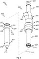
- FIG. 1 shows a longitudinal sectional view of an in particular, according to the invention, front part 200 and a drive part 300 disassembled inventive injector 100.
- the illustrated tubular front part 200 consists of a mouthpiece 210 with a sealing element DE, such as an O-ring at a mouth end 201 of the front part 200 and an adjusting element 220 at a connecting end 202 opposite the mouth end 201.
- the illustrated adjusting element 220 comprises a ring nut 222 and an adapter 221 with a further sealing element DE in the form of an O-ring.
- the illustrated front part 200 can via the mouthpiece 210 by conventional methods, for example by a retaining ring (not shown), fixed to a mold (not shown) are mounted.
- the illustrated mouthpiece 210 has an external thread and is thus screwed into the front part 200.
- the illustrated mouthpiece 210 has, for example, to the longitudinal axis LA of the front part 200 coaxial, bore 211, which extends from the front side 200 connected to the first side parallel to the axis and finally tapered.
- a nozzle 331 of the drive 300 can be inserted at the mounting curtain.
- an external thread on which the ring nut 222 and the adapter 221 are screwed.
- a length of the front part 200 along the longitudinal axis LA can be adjusted.
- a close tolerance of the item dimensions is therefore not required, which in favor of the production costs. It goes without saying that if the tolerances of the component dimensions were sufficiently narrow, it would be possible to dispense with the ring nut 222 and all components would be screwed firmly against one another. However, this would unnecessarily increase the manufacturing costs.
- a sealing element DE is attached, which seals the front part 200 and the drive member 300 in the mounted state against the atmosphere.
- the placement at this position allows quick and easy maintenance, because the testing and possibly replacement falls easier than if the sealing element DE inside the connecting device 400 would be installed, since it is well positioned.
- the front part 200 consists of few components. The majority of the parts of the illustrated injector 100 are located on the side of the drive part 300. Additional forms must always be equipped with front parts 200 only. The acquisition of complete injectors 100 is therefore eliminated. Thus, the current investment costs for various forms can be kept low.
- the driving part 300 of the illustrated injector 100 includes, for example, a nozzle 331, an inner tube 330, a connecting device 400, and a material port 342.
- the illustrated driving part 300 can be inserted into the front part 200 and fixed by the connecting device 400 in its position along the longitudinal axis LA ,
- the connecting device 400 in its position along the longitudinal axis LA .
- only the operating element 440 in the form of an annular recess on the outside of the frame member 450 of the connecting device 400 in particular by hand, against the spring force of the spring element 430 in the form of a coil spring from a shown operating position moved to a mounting position, so that the frame element 450 radially releases the connectors 410 fixed in the form of balls.
- the adapter 221 of the front part 200 can then be inserted into the frame member 450.
- the frame member 450 is pushed back into the operating position.
- the connectors 410 engage in the counter connectors 420 in the form of a circumferential groove of the adapter 221.
- front part 200 and drive part 300 are connected to one another in a form-fitting manner along the longitudinal axis LA. No additional tools are required for this.
- the drive part 300 is already guided during insertion into the front part 200.
- mounted chamfer 332 can not lead to a tilting between the adapter 221 and frame member 450 or between the nozzle 331 and mouthpiece 210 during an assembly process. The assembly can thus easily perform in hard to reach places a form.
- the injector 100 can be connected to a hose (not shown) to an external material silo (not shown).
- an internal thread (not shown) is provided in the material connection 342, for example, into which customary hose adapters can be screwed.
- a double-acting pneumatic cylinder 350 is actuated, which is designed to close the bore 211 of the mouthpiece by displacing a piston 310 screwed onto a piston rod 311 from a filling position shown to a closing position.
- a seal (not visible) may be included, which seals the pneumatic cylinder 350.
- the pneumatic cylinder 350 is another piston (not visible) on the piston rod 311 attached. The further piston can be displaced by application of compressed air via at least one of the two pneumatic ports 341 along the longitudinal axis LA in order to displace the piston 310 from the filling position into the closed position and vice versa.
- the illustrated piston 310 is attached to the piston rod 311, for example, with a lock nut 313 on an external thread on the nozzle side. This design allows for length adjustability of the piston 310 and piston rod system 311.
- the illustrated drive part 300 comprises a compressed air connection 340 for introducing the blowing air for the filling process, which is passed through the nozzle 331, for example, into a cavity of the mold.
- the illustrated nozzle 331 is screwed into the inner tube 330, for example.
- a sealing element DE in the form of an O-ring, which prevents in the mounted state that air flows through the annular gap between the nozzle 331 and mouthpiece 210.
- the compressed air is passed through the nozzle bores 333 and thus introduced at a defined angle in the mouthpiece 210 and thus in a cavity of the mold.
- the illustrated inner tube 330 is, for example, screwed into the drive part 300 by means of an outer thread present at the end facing away from the nozzle 331 and can be secured in a material-locking manner with a thread-locking adhesive.
- connection device 400 is also firmly screwed into the drive part 300, and the screw connection can be secured with adhesive.
- the illustrated connecting device 400 comprises a frame element 450 with a plurality of connectors 410 in the form of balls, which sit in a plurality of, in particular about the longitudinal axis LA evenly distributed, conical bores and can move only in the radial direction to the longitudinal axis LA when the frame element 450 is pulled against a force of the spring element 430 from the illustrated operating position to the mounting position.
- FIG. 2 shows an enlargement of the Z marked portion of FIG. 1 ,
- the counter-connector 420 in the form of a circumferential groove and the sealing element DE in the form of an O-ring can be clearly seen. Due to the illustrated positioning of the sealing element DE, the front part 200 and the drive part 300 can be particularly airtightly interconnected with only one sealing element DE, which is also easily accessible for maintenance, so that no compressed air can escape uncontrollably from the injector 100.
- FIG. 3 shows a perspective drawing of the injector 100 from FIG. 1 .
- the drive part 300 can be inserted into the front part 200 along the longitudinal axis LA.
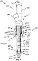
- FIG. 4 shows a longitudinal sectional view of the injector 100 FIG. 1 wherein front part 200 and drive part 300 are fixed to each other along the longitudinal axis LA by the connection device 400.
- the piston 310 is in a filling position.
- compressed air of a form connected to the mouthpiece 210 of the injector 100 can be supplied via a compressed air connection 340.
- This flows through the gap between front part 200 and inner tube 330 to its end facing the mouthpiece 210, where the compressed air is directed through a number of nozzle bores 333 focused into the mouthpiece 210 and thus into a cavity of the mold.
- Due to the resulting negative pressure in the inner tube 330 plastic particles are sucked through the material connection 342 from a material silo (not shown) and transported into the cavity.
- the material connection 342 may have a material connection axis MAA, which is inclined with respect to the longitudinal axis LA.
- the nozzle 331 is easily accessible in the split state of the injector 100, it can be replaced without much effort. This is necessary, for example, if the air consumption of the injector is to be adapted to the material to be processed.
- the same drive part 300 can therefore - be used optimally - with several exchangeable nozzles - for different plastics (with different densities).
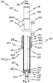
- FIG. 5 shows a longitudinal sectional view of the injector 100 FIG. 1 wherein front part 200 and drive part 300 are fixed to each other along the longitudinal axis LA by the connection device 400.
- the piston 310 in a closed position in which the bore 211 of the mouthpiece 210 is closed by the piston 310.
- the piston 310 may have at least one sealing element DE, for example an O-ring.
- the piston 310 In the closed position, plastic foaming in a mold connected to the mouthpiece 210 (not shown) is prevented from penetrating into the injector 100.
- the piston 310 In the closed position, the piston 310 is flush with the side of the mouthpiece 310 facing the mold. Otherwise, could arise by the protrusion or backward of the piston 310 on the foamed molding an undesirable impression of the same.
- the lengths of the front part 200, piston 310 and piston rod 311 along the longitudinal axis LA must be precisely matched to one another.
- the illustrated front part 200 has a ring nut 222, which secures the position of the adapter 221 on the front part 200 along the longitudinal axis LA.
- the position of the piston 310 along the longitudinal axis LA for example, by a lock nut 313 set and fix. Both parts can thus be factory-set to a reference size. A particularly close tolerance of the item dimensions is therefore not required, which has an effect in favor of the manufacturing cost. It goes without saying that, given sufficiently close tolerancing of the component dimensions, the ring nut 222 and the lock nut 313 could be dispensed with, and in particular all components could be screwed firmly against one another. However, this would unnecessarily increase the manufacturing costs.
- FIG. 6 shows a perspective drawing of the injector 100 from FIG. 4 .
- FIG. 7 shows an enlargement of the X marked portion of FIG. 6 .
- the illustrated frame element 450 is shaped on its inside in such a way that it radially fixes the spherical connectors 410 in the groove-shaped counter connector 420 of the adapter 222 in the illustrated operating position. If the illustrated frame member 450 against the force of the spring element 430th shifted to the drive part 300 to the mounting position, the connectors 410 can move radially outwardly in a recess 451 running around on the inside of the frame element 450. As a result, the connectors 410 are no longer fixed in the counterconnectors 420, so that the front part 200 can be pulled out of the connection device 400 and thus separated from the drive part 300.
- FIG. 8 shows a schematic representation of a front parts 200 according to the invention (only labeled as an example) fitted F. Furthermore, the form F a number of ejector AS (only labeled as an example), so that the space for mounting drive parts (not shown) to the Front parts 200 is very cramped.
- FIG. 9 shows a schematic representation of the form F from FIG. 8 , wherein the mold F is equipped with injectors 100 according to the invention (labeled only by way of example).
- the driving parts 300 of the injectors 100 can be rotated about the longitudinal axes of the front parts 200 of the injectors 100.
- supply lines (not shown in particular) for plastic particles can be easily connected to the material connections 342 of the drive parts 300 despite the restricted space, for example, due to ejector rods AS and / or further injectors.
- FIG. 10 2 shows a schematic illustration of a method 500 according to the invention.
- the method 500 includes loading 510 of a number of shapes F with, in particular, front parts 200 of injectors 100 according to the invention.
- fastening 520 of drive parts 300 to the front parts 200 on at least one mold F take place to provide on the mold F injectors 100 according to the invention.
- the drive parts 300 may, after fastening 520, experience an alignment 530 about a respective longitudinal axis LA of the front parts 200. By aligning 530, subsequent connection 550 of supply lines, for example for compressed air and / or plastic particles, on the drive parts 300 is facilitated.
- the production of molded parts in the form F can follow the abovementioned preparation steps.
- the manufacture comprises, for example, filling 560 of the mold F with plastic particles through the injectors 100; closing 565 the filling holes of the mold F, to which the injectors 100 are connected, by pistons 310 of the injectors 100; foaming 570 of the plastic particles in the form F and ejecting 580 of the foamed plastic molded part from the mold F, for example by ejector rods AS and / or the pistons 310 of the injectors 100.
- the filling 560, 565 closing, foaming 570 and ejecting 580 can be repeated until the desired amount of moldings made with the mold F. is.
- a loosening 540 of the drive parts 300 can take place from the front parts 200 connected to the mold F. This may be followed by fastening 520 of the drive parts 300 to the front parts 200 connected to the further form F, followed by the further method steps which may follow in the case of the form F.
- a variety of shapes F can be used with a small number of driving parts 300.
- a waiting 590 of the separate front parts 200 and / or drive parts 300 for example, with a cleaning and / or a review and / or replacement of wearing parts done.
- wearing parts are advantageously arranged so that they are easily accessible when the front parts 200 and drive parts 300 of the injectors 100 are separated from one another.
- FIG. 11 shows a schematic representation of a production plant according to the invention 600.
- the illustrated production plant 600 for the production of plastic moldings in a number of forms F with at least one foaming machine 601 comprises a loading station 620 for loading 510 of the forms F with, in particular according to the invention, front parts 200th
- the illustrated manufacturing plant 600 further includes a setup station 610 for mounting 520 drive members 300 to the front portions attached to at least one of the molds F to form injectors 100 of the invention and / or to release 540 the drive members 300 from the front portions 200.
- the production plant 600 shown comprises a transport system 630 for transporting the molds F, for example in the form of a rail system connecting the foaming machine 601, the set-up station 610 and / or the loading station 620 with a number of transport robots guided thereon.
Landscapes
- Injection Moulding Of Plastics Or The Like (AREA)
Abstract
Description
- Die Erfindung betrifft einen Injektor zum Befüllen einer Form mit Kunststoffteilchen gemäß dem Oberbegriff des Anspruchs 1. Die Erfindung betrifft ein Vorderteil für einen Injektor zum Befüllen einer Form mit Kunststoffteilchen gemäß dem Oberbegriff des Anspruchs 8. Die Erfindung betrifft außerdem ein Verfahren und eine Produktionsanlage zur Herstellung von Formteilen aus Kunststoff in einer Anzahl von Formen.
- Im Herstellungsprozess von Formteilen aus aufschäumbaren Kunststoffen müssen bei Werkzeugwechsel, d.h. wenn der Schäumautomat von einem auf ein anderes Formteil umgerüstet werden soll, Injektoren, durch die Kunststoffteilchen mit Druckluft in eine Form, in der der Kunststoff aufgeschäumt wird, eingeleitet werden, von der Form demontiert und auf die nachfolgende Form montiert werden. Dieser Arbeitsschritt kostet Zeit und somit Geld. Da der Umbau in der Regel aufwendig ist, steht die Produktion für einen Zeitraum still, was die Teilkosten in die Höhe treibt. Alternativ können die Formen allesamt mit jeweils eigenen Injektoren bestückt werden, was die Rüstzeiten zwar minimiert, die Investitionskosten jedoch enorm in die Höhe treibt. Im Zuge der zunehmend bedarfssynchronen Produktion ("Just-in-Time-Produktion") spielen Rüstprozesse eine immer wichtigere Rolle.
- Neben dem Umrüsten bei Werkzeugwechsel müssen im laufenden Produktionsprozess Injektoren unter ungünstigen Umständen im Inneren gereinigt werden, da es beim Füllvorgang zum Verstopfen und Verschweißen des Kunststoffes in den Injektoren selbst kommen kann. Auch dazu ist eine aufwendige Demontage der Injektoren von der Form notwendig.
- Um das Umrüsten und Reinigen zu beschleunigen und die Kosten im Rahmen zu halten, können geteilte Injektoren eingesetzt werden. Diese bilden einen Kompromiss zwischen Investitions- und Rüstkosten. Die bislang auf dem Markt angebotenen Ausführungen lassen sich jedoch nur umständlich und mit Hilfe von zusätzlichem Werkzeug teilen.
- Die Patentanmeldung
DE 10 2009 024 278 A1 offenbart einen teilbaren Injektor, bei dem ein Rohr, beispielsweise durch eine Schraubverbindung mit einer Überwurfmutter, lösbar mit einem Anschlussstück verbunden ist. Nachteilig an eine Schraubverbindung ist, dass sie mit einem definierten Drehmoment angezogen werden muss, um einerseits sicherzustellen, dass die Verbindung durch den im Betrieb in dem Injektor herrschenden Überdruck, der typischerweise im Bereich von 6 bis 8 bar liegt, nicht gelöst wird, und andererseits Beschädigungen des Injektors durch ein zu starkes Anziehen zu verhindern. Dazu sind spezielles Werkzeug und geschultes Personal notwendig, wodurch die Montage und Demontage des Injektors teuer und aufwändig sind. Weiterhin ist es nicht möglich, die Ausrichtung des Anschlussstücks nach dem Verbinden zu korrigieren, beispielsweise um Zuleitungen eines Schäumautomaten für Druckluft oder Kunststoffteilchen besser an dem Anschlussstück anschließen zu können. Daher müssen Rohr und Anschlussstück gegebenenfalls im schwer zugänglichen Inneren des Schäumautomaten mehrmals verbunden und getrennt werden, um eine geeignete Ausrichtung zu finden, was wiederum die Rüstzeiten und -kosten in die Höhe treibt. - Die Patentanmeldung
DE 10 2013 114 170 A1 beschreibt einen Injektor mit einem Vorderteil und einem Basisteil, die über eine Steckverbindung mit korrespondierenden Halbringnuten und diese durchgreifenden Steck- oder Passstiften verbunden sein können. Die Teile können ferner durch Gewindebolzen verbunden sein. Nachteilig daran ist, dass die Stifte nicht mit dem Injektor verbunden sind, sodass sie bei der Montage oder Demontage leicht verloren gehen können. Ferner müssen die Teile mit einer geringen Toleranz gefertigt sein, damit eine Steckverbindung die notwendige Dichtheit und Stabilität gegenüber dem im Betrieb in dem Injektor herrschenden Überdruck sicherstellen kann. Daher ist die Herstellung des beschriebenen Injektors aufwändig und teuer. Weiterhin ist es auch hier nicht möglich, die Ausrichtung des Basisteils nach dem Verbinden zu korrigieren. - Daraus ergibt sich die technische Aufgabe, möglichst einfach und kostengünstig herzustellende Vorrichtungen und möglichst einfach durchzuführende Verfahren zu schaffen, die eine zuverlässige Herstellung von Formteilen aus Kunststoff zeit- und kosteneffizienter ermöglichen als Lösungen aus dem Stand der Technik.
- Diese Aufgabe wird durch einen Injektor nach Anspruch 1, ein Vorderteil für einen Injektor gemäß Anspruch 8, ein Verfahren gemäß Anspruch 11 und eine Produktionsanlage gemäß Anspruch 14 gelöst. Vorteilhafte Ausführungen ergeben sich aus den davon abhängigen Ansprüchen.
- Ein erfindungsgemäßer Injektor zum Befüllen einer Form mit Kunststoffteilchen umfasst ein insbesondere rohrförmiges und/oder erfindungsgemäßes, Vorderteil mit einem Mündungsende zum Anschluss an die Form und ein Antriebsteil zur Anordnung an einem dem Mündungsende gegenüberliegenden Verbindungsende des Vorderteils. Das Antriebsteil umfasst einen in das Vorderteil einführbaren Kolben sowie einen Antrieb zur Bewegung des Kolbens entlang einer Längsachse des Vorderteils. Der Kolben kann von dem Antrieb in eine Befüllposition und eine Verschlussposition bewegt werden. In der Verschlussposition verschließt der Kolben eine Einfüllöffnung der Form, an der der Injektor angeschlossen ist, beispielsweise um ein Austreten von Kunststoff während eines Aufschäumens des Kunststoffs zu verhindern. In der Befüllposition ist der Kolben von der Einfüllöffnung zurückgezogen und erlaubt so ein Einströmen von Kunststoffteilchen und/oder Druckluft durch den Injektor und die Einfüllöffnung in die Form. Die Kunststoffteilchen können beispielsweise als Pulver oder Granulat vorliegen. Die Kunststoffteilchen und/oder jedes einzelne Kunststoffteilchen können insbesondere aus genau einem Kunststoff oder aus einer Mischung mehrerer Kunststoffe bestehen. Ein solcher Kunststoff ist bevorzugt aufschäumbar, wie beispielsweise expandierbares Polystyrol, Polypropylen oder Polyethylen.
- Der Injektor umfasst eine Verbindungsvorrichtung zur lösbaren Fixierung des Antriebsteils in vorzugsweise zumindest radialer und axialer Richtung bezüglich der Längsachse an dem Vorderteil, wobei das Antriebsteil um die Längsachse drehbar an dem Vorderteil gelagert sein kann. Durch eine Fixierung in radialer und axialer Richtung wird sichergestellt, dass die Teile im Betrieb des Injektors zuverlässig aneinander gehalten werden, so dass die Gefahr von Unfällen, Fehlfunktionen und/oder Beschädigungen durch ein sich lösendes Antriebsteil und/oder unkontrolliert austretende Druckluft und/oder Kunststoffteilchen minimiert wird. Eine radiale Fixierung kann beispielsweise auf einfache Weise erreicht werden, indem das Vorderteil, die Verbindungsvorrichtung und das Antriebsteil in radialer Richtung formschlüssig verbunden, insbesondere ineinander gesteckt, sind. Durch eine um die Längsachse drehbare Lagerung ist es möglich, die Ausrichtung des Antriebsteils in einem mit dem Vorderteil verbundenen Zustand durch eine Drehung um die Längsachse zu justieren, beispielsweise um Zuleitungen für Druckluft und/oder Kunststoffteilchen in einem Schäumautomaten einfacher an das Antriebsteil anschließen zu können.
- Die Verbindungsvorrichtung kann an dem Antriebsteil befestigt sein. Dadurch kann die Verbindungsvorrichtung zusammen mit dem Antriebsteil auf einfache Weise von einem Vorderteil an ein anderes Vorderteil überführt werden. Weiterhin kann das Vorderteil besonders einfach aufgebaut sein. Das ist insbesondere dann von Vorteil, wenn das Vorderteil bei einem Umrüstvorgang zur Zeitersparnis an der Form verbleiben soll. In diesem Fall können durch ein einfach aufgebautes Vorderteil erhebliche Kosten eingespart werden. Es ist jedoch auch denkbar, die Verbindungsvorrichtung nicht an den Antriebsteil sondern an dem Vorderteil zu befestigen.
- Die Verbindungsvorrichtung kann beispielsweise durch eine Schraub- oder Klemmverbindung oder eine stoffliche Verbindung an dem Antriebsteil befestigt sein. Insbesondere kann das Antriebsteil ein Innengewinde aufweisen, in das ein korrespondierendes Außengewinde der Verbindungsvorrichtung eingeschraubt und vorteilhafterweise mit Gewindesicherungsklebstoff gesichert ist. Selbstverständlich ist auch die umgekehrte Verteilung von Innengewinde und Außengewinde denkbar. Eine Schraubverbindung hat den Vorteil, dass dadurch unterschiedlich ausgelegte Verbindungsvorrichtungen und/oder Antriebsteile modular miteinander kombiniert werden und sicher aneinander befestigt werden können.
- Die Verbindungsvorrichtung kann eine Anzahl von Konnektoren zur Fixierung der Verbindungsvorrichtung an dem Antriebsteil oder an dem Vorderteil in axialer Richtung bezüglich der Längsachse umfassen. Die Konnektoren können zum Beispiel Federelemente umfassen, die, insbesondere wie bei einer Steckschnalle oder einem Steckschloss, federnd in Federelementaufnahmen eingreifen, um in axialer Richtung eine kraftschlüssige Verbindung der Verbindungsvorrichtung mit dem Vorderteil oder dem Antriebsteil herzustellen.
- Die Konnektoren können dazu ausgelegt sind, mit einer Anzahl von Gegenkonnektoren an dem Vorderteil oder dem Antriebsteil gegenüber einer Bewegung entlang der Längsachse formschlüssig zusammenzuwirken. Vorteilhafterweise weisen Konnektoren und Gegenkonnektoren in einer die Längsachse umfassenden Schnittebene komplementäre Formen auf. Dadurch können Sie in axialer Richtung besonders zuverlässig formschlüssig zusammenwirken. Beispielsweise können die Konnektoren als radiale Vorsprünge und die Gegenkonnektoren als radiale Vertiefungen oder umgekehrt ausgebildet sein. Vorteilhafterweise ist eine radiale Vertiefung als um die Längsachse umlaufende Nut ausgestaltet, da somit in die Nut eingreifende Konnektoren oder Gegenkonnektoren bezüglich einer Rotation um die Längsachse beweglich und gleichzeitig in axialer und radialer Richtung fixiert sein können. Weiterhin kann durch eine umlaufend gleichmäßige Fixierung eine besonders sichere Befestigung gegenüber dem im Betrieb des Injektors in dessen Innerem herrschenden Überdruck erreicht werden.
- Besonders vorteilhaft sind die in die Nut eingreifenden Konnektoren oder Gegenkonnektoren als Kugeln oder Walzen ausgebildet, sodass sie mit der Nut ein Kugel- oder Wälzlager bilden, das eine besonders leichtgängige und verschleißarme Rotation erlaubt. Eine Ausgestaltung als Kugeln bietet den zusätzlichen Vorteil, dass die Kugeln so angeordnet sein können, dass sie auch beim Zusammenstecken oder Auseinanderziehen Vorderteil und Antriebsteil aneinander führen und somit Reibung und Verschleiß reduzieren.
- Vorteilhafterweise können die Konnektoren und/oder die Gegenkonnektoren aus einem verschleißbeständigen Material, beispielsweise rostfreiem Stahl, Messing oder hochfestem Aluminium, hergestellt sein und/oder eine verschleißbeständige Beschichtung, beispielsweise aus Aluminiumnitrid, Wolframcarbid oder amorphem Kohlenstoff, aufweisen. Dadurch wird sichergestellt, dass die Konnektoren und/oder Gegenkonnektoren den Belastungen bei Montage und Demontage sowie durch den Überdruck im Betrieb des Injektors standhalten, sodass eine lange Lebensdauer und ein sicherer Betrieb des Injektors gewährleistet sind.
- Vorteilhafterweise können die Konnektoren an der Verbindungsvorrichtung und/oder die Gegenkonnektoren an dem Vorderteil und/oder dem Antriebsteil radial zur Längsachse beweglich gelagert sein. Dadurch können die Konnektoren und/oder Gegenkonnektoren von einer Betriebsposition in eine Montageposition radial verschoben werden, wobei sie in der Betriebsposition in axialer Richtung formschlüssig zusammenwirken, so dass die Verbindungsvorrichtung an dem Vorderteil und dem Antriebsteil in axialer Richtung fixiert ist. In der Montageposition wirken die Konnektoren und Gegenkonnektoren nicht in axialer Richtung formschlüssig zusammen, so dass das Antriebsteil in axialer Richtung von dem Vorderteil abgezogen werden kann.
- Vorteilhafterweise ist die Verbindungsvorrichtung an dem Vorderteil oder dem Antriebsteil radial geführt, so dass die Teile ohne zu verkanten zusammengeschoben oder auseinandergezogen werden können.
- Die Verbindungsvorrichtung kann ein von einer Betriebsposition in eine Montageposition verschiebbares Rahmenelement umfassen, wobei das Rahmenelement die Konnektoren und/oder Gegenkonnektoren in der Betriebsposition in einer in axialer Richtung formschlüssig zusammenwirkenden Position fixiert und in der Montageposition für eine Bewegung radial zur Längsachse frei gibt. Durch das Rahmenelement können die Konnektoren und/oder Gegenkonnektoren zum einen in ihrer Betriebsposition fixiert werden, um einen sicheren Betrieb des Injektors zu gewährleisten, und zum anderen freigegeben werden, um das Antriebsteil auf einfache Weise von dem Vorderteil zu trennen. Das Rahmenelement kann die Verbindungsvorrichtung beispielsweise ringförmig umschließen. Es kann an seiner Innenseite so ausgestaltet sein, dass es in der Betriebsposition die Konnektoren und/oder Gegenkonnektoren in radialer Richtung formschlüssig fixiert und in der Montageposition eine radiale Bewegung der Konnektoren und/oder Gegenkonnektoren, beispielsweise in eine Ausnehmung des Rahmenelements, erlaubt.
- Vorteilhafterweise ist das Rahmenelement entlang der Längsachse verschiebbar. Dadurch kann in einem einheitlichen Bewegungsablauf das Rahmenelement aus der Betriebsposition in Montageposition verschoben und das Antriebsteil von dem Vorderteil in zur Längsachse axialer Richtung abgezogen werden. Analog kann in einem weiteren einheitlichen Bewegungsablauf das Antriebsteil auf das Vorderteil aufgesteckt und das Rahmenelement aus der Montageposition in die Betriebsposition verschoben werden. Ferner verursacht ein Überdruck im Inneren des Injektors während dessen Betrieb im Bereich der Verbindungsvorrichtung hautsächlich radial zur Längsachse nach außen wirkende Kräfte. Daher kann das Rahmenelement nicht durch den Überdruck entlang der Längsachse aus der Betriebsposition in die Montageposition verschoben werden, wodurch Druckluft unkontrolliert austreten und/oder das Antriebsteil unkontrolliert von dem Vorderteil getrennt werden könnte.
- Vorteilhafterweise können das Rahmenelement, die Konnektoren und/oder die Gegenkonnektoren so ausgelegt sein, dass sie beim Erreichen ihrer Betriebsposition hörbar und/oder spürbar einrasten. Dadurch kann auf einfachste Weise überprüft werden, dass die Betriebsposition erreicht und somit ein sicherer Betrieb des Injektors möglich ist. Alternativ oder ergänzend kann die Verbindungsvorrichtung ein Anzeigeelement umfassen, das das Erreichen der Betriebsposition anzeigt. Das Anzeigeelement kann beispielsweise eine farbliche Markierung umfassen, die von dem Rahmenelement bei Erreichen der Betriebsposition verdeckt oder freigelegt wird.
- Insbesondere kann ein Federelement das Rahmenelement in der Betriebsposition halten. Im einfachsten Fall kann das Federelement beispielsweise als Spiralfeder ausgeführt sein. Vorteilhafterweise ist eine Kraft des Federelements größer gewählt, als eine Kraft die, insbesondere im Betrieb des Injektors, beispielsweise bei einer unbeabsichtigten Berührung des Injektors durch einen Nutzer und/oder einen Schäumautomaten, für eine Verschiebung des Rahmenelements aus der Betriebsposition heraus zu erwarten ist, wobei insbesondere eine Sicherheitsmarge berücksichtigt sein kann. Dadurch wird sichergestellt, dass sich das Rahmenelement nicht während des Betriebs des Injektors in die Montageposition verschiebt, wodurch das Antriebsteil unkontrolliert von dem Vorderteil getrennt werden könnte.
- Als Schutz vor einem zu hohen Druck im Inneren des Injektors kann der Injektor ein Überdrucksicherung, beispielsweise ein Überdruckventil, eine Überdruckklappe oder eine Sollbruchstelle umfassen.
- Die Verbindungseinrichtung kann ein Bedienelement, bevorzugt einen Handgriff und/oder eine Grifffläche, zum Lösen der Fixierung der Verbindungseinrichtung an dem Antriebsteil oder an dem Vorderteil umfassen. In einer besonders einfachen Ausgestaltung kann eine Außenfläche eines Rahmenelements als Grifffläche ausgebildet sein.
- Vorteilhafterweise ist das Bedienelement dazu ausgelegt, die Fixierung durch Überwinden einer Kraft eines Federelements zu lösen. Beispielsweise kann zum Lösen ein Rahmenelement gegen eine Federkraft einer Feder verschoben werden. Dadurch ist eine besonders einfache, insbesondere werkzeuglose, Montage und Demontage möglich, da keine weiteren Sicherungsmittel, wie zum Beispiel Muttern oder Schrauben, gelöst oder befestigt werden müssen. Um ein versehentliches Lösen zu vermeiden, kann das Bedienelement ein Verriegelungselement, beispielsweise einen Schalter, umfassen, der betätigt werden muss, um das Rahmenelement aus der Betriebsposition heraus zu verschieben.
- Das Bedienelement ist vorteilhafterweise an dem Injektor befestigt, beispielsweise indem es den Injektor, insbesondere als Rahmenelement, ringförmig umschließt. Alternativ oder ergänzend kann das Bedienelement, beispielsweise mit einem Draht, an dem Injektor angebunden sein. Durch die Befestigung wird verhindert, dass das Bedienelement bei der Montage oder Demontage herunter fällt oder, z.B. in einem schwer zugänglichen Teil des Schäumautomaten, verlorengeht. Dadurch ist eine schnellere und einfachere Montage und Demontage möglich.
- Der Injektor kann ein Innenrohr zur Anordnung in dem Vorderteil umfassen. Durch das Innenrohr können auf einfache Weise zwei voneinander getrennte Strömungskanäle für Kunststoffteilchen und Druckluft realisiert werden. So können beispielsweise die Kunststoffteilchen im Inneren des Innenrohrs und die Druckluft im Zwischenraum zwischen dem Innenrohr und einem Mantel des Vorderteils getrennt voneinander geführt werden. Für einen einfachen Aufbau des Injektor es ist das Innenohr vorteilhafterweise koaxial in dem Vorderteil angeordnet.
- Das Innenrohr kann an dem Antriebsteil, insbesondere durch eine Schraubverbindung, befestigt sein. Ist das Innenrohr an dem Antriebsteil befestigt, kann das Vorderteil besonders einfach aufgebaut sein, und das Innenrohr kann gemeinsam mit dem Antriebsteil von dem Vorderteil abgenommen werden, beispielsweise um es zu reinigen oder zu warten.
- Das Innenrohr kann an seinem dem Mündungsende zugewandten Ende eine Fase aufweisen. Dadurch kann das Innenrohr besonders einfach, insbesondere ohne zu verkanten, in das Vorderteil eingeführt werden.
- Das Innenrohr kann an seinem dem Mündungsende zugewandten Ende eine Düse mit zur Längsachse geneigten Düsenbohrungen zur Führung von Druckluft an das Mündungsende aufweisen. Durch die Düse können die Druckluft und somit auch die Kunststoffteilchen unter einem definierten Winkel in die Form eingebracht werden, um diese gleichmäßig mit Kunststoff auszufüllen. Dadurch können Formteile von besonders hoher Qualität hergestellt werden.
- Der Antrieb kann eine, bevorzugt entlang der Längsachse verstellbar, an dem Kolben befestigte Kolbenstange umfassen. Die Kolbenstange kann beispielsweise in den Kolben eingeschraubt und insbesondere durch eine Mutter gesichert sein. Durch eine Verstellbarkeit entlang der Längsachse kann die Länge des Systems aus Kolben und Kolben und Kolbenstange so eingestellt werden, dass der Kolben in seiner Verschlussposition mit dem Mündungsende bündig abschließt. Dadurch wird sichergestellt, dass beim Aufschäumen der Kunststoffteilchen an der von dem Kolben verschlossenen Einfüllöffnung der Form kein Abdruck des Kolbens entsteht. Ferner ist bei der Herstellung des Antriebsteils eine höhere Toleranz bezüglich der Länge und/oder Positionierung von Kolben und/oder Kolbenstange möglich, da Abweichungen von einer Soll-Länge und/oder Soll-Position durch die Verstellbarkeit kompensiert werden können. Dadurch sinken die Herstellungskosten des Antriebsteils. Außerdem kann die Länge des Systems aus Kolben und Kolbenstange für die Verwendung mit unterschiedlichen Vorderteilen angepasst werden.
- Der Antrieb kann einen an dem von dem Kolben abgewandten Ende der Kolbenstange befestigten Antriebskolben, der in einem Pneumatikzylinder entlang der Längsachse verschiebbar angeordnet ist, umfassen. Dadurch kann der Injektor rein pneumatisch betrieben werden, so dass neben Zuleitungen für Druckluft und Kunststoffteilchen keine weiteren Versorgungs- oder Steuerungsleitungen an dem Injektor angebracht sein müssen. Somit sind ein besonders einfacher Aufbau des Injektors und eine einfache Montage und Demontage möglich.
- Ein erfindungsgemäßes, insbesondere rohrförmiges, Vorderteil für einen, insbesondere erfindungsgemäßen, Injektor zum Befüllen einer Form mit Kunststoffteilchen umfasst ein Mündungsende zum Anschluss des Vorderteils an die Form und ein dem Mündungsende gegenüberliegendes Verbindungsende zur Verbindung des Vorderteils mit einem Antriebsteil des Injektors. Im einfachsten Fall ist das Vorderteil im Wesentlichen zylinderförmig, sodass es einfach und kostengünstig hergestellt werden kann.
Zum Anschluss an die Form kann das Vorderteil an seinem Mündungsende zum Beispiel ein Gewinde und/oder ein Klemmmittel wie einen Befestigungsflansch umfassen. Vorteilhafterweise umfasst das Vorderteil an seinem Mündungsende ein Außengewinde, da das Vorderteil damit mit einer einstellbaren Einbautiefe stabil mit der Form verbunden werden kann, ohne dass eine Strömung von Druckluft und/oder Kunststoffteilchen im Inneren des Vorderteils gestört wird. Eine einstellbare Einbautiefe ist deshalb vorteilhaft, weil das Vorderteil mit einer Innenseite der Form bündig abschließen muss, um ein Formteil mit einer gleichmäßigen Oberfläche zu erzeugen. - Das Vorderteil kann ein Einstellelement zum Einstellen einer Länge des Vorderteils entlang einer Längsachse des Vorderteils umfassen. Durch das Einstellelement kann die Länge des Vorderteils so eingestellt werden, dass ein in das Vorderteil zum Verschließen einer Einfüllöffnung der Form eingeführten Kolben des Injektors mit dem Mündungsende bündig abschließt. Dadurch wird sichergestellt, dass beim Aufschäumen der Kunststoffteilchen an der von dem Kolben verschlossenen Einfüllöffnung der Form kein Abdruck des Kolbens entsteht. Ferner ist bei der Herstellung des Vorderteils eine höhere Toleranz bezüglich der Länge des Vorderteils möglich, da Abweichungen von einer Soll-Länge durch das Einstellelement kompensiert werden können. Dadurch sinken die Herstellungskosten des Vorderteils. Außerdem kann die Länge des Vorderteils für die Verwendung mit unterschiedlichen Antriebsteilen angepasst werden.
- Das Einstellelement kann einen an dem Verbindungsende entlang der Längsachse verstellbar befestigten Adapter zur Verbindung des Vorderteils mit dem Antriebsteil und/oder einer Verbindungsvorrichtung umfassen. Das Vorderteil kann insbesondere ein Gewinde aufweisen, auf das der Adapter und/oder eine Ringmutter zur Sicherung des Adapters aufgeschraubt sind. Der Adapter kann beispielsweise als das Vorderteil umschließende Hülse ausgestaltet sein, die insbesondere eine Anzahl von Gegenkonnektoren zur entlang der Längsachse formschlüssigen Verbindung mit Konnektoren der Verbindungsvorrichtung aufweisen kann. Besonders vorteilhaft kann ein Gegenkonnektor als umlaufende Nut ausgebildet sein, in der die Konnektoren entlang der Längsachse fixiert und um die Längsachse drehbar gelagert sein können.
- Das Vorderteil kann eine Montagehilfe zur einfachen und sicheren Befestigung des Antriebsteils an dem Vorderteil umfassen. Die Montagehilfe kann ein an dem Mündungsende angeordnetes Mundstück umfassen. Das Mundstück umfasst eine, bevorzugt zur Längsachse koaxiale, Bohrung, die zu einem dem Mündungsende zugewandten Ende eines in das Vorderteil einzuführenden Innenrohrs komplementär geformt ist und sich bevorzugt zumindest abschnittsweise in einer Einführrichtung des Innenrohrs entlang der Längsachse konisch verjüngt. Das Mundstück kann lösbar an dem Vorderteil befestigt, beispielsweise angeschraubt, sein. Dadurch können unterschiedliche Mundstücke, die sich zur Verwendung mit unterschiedlichen Formen, beispielsweise in ihrer Länge, unterscheiden, mit dem Vorderteil kombiniert werden. Das Mundstück kann einen Code, beispielsweise einen Farb-, Zahlen-, Buchstaben-, Bar- und/oder QR-Code, aufweisen, aus dem hervorgeht, zur Verwendung mit welcher Form sie vorgesehen sind. Das Mundstück kann auch fest, beispielsweise stoffschlüssig, mit dem Vorderteil verbunden und insbesondere einstückig mit dem Vorderteil ausgebildet sein. Dadurch kann auf einfache Weise eine besonders hohe mechanische Stabilität des Vorderteils erreicht werden.
- Die Montagehilfe kann einem Anzeigemittel zur Anzeige eines bündigen Abschlusses eines in das Vorderteil eingeführten Kolbens des Antriebsteils mit dem Mündungsende umfassen. Mit Hilfe des Anzeigemittels kann überprüft werden, dass eine verstellbare Länge des Vorderteils und/oder eine verstellbare Länge und/oder Position des Kolbens für einen bündigen Abschluss korrekt justiert sind. Dadurch wird sichergestellt, dass beim Aufschäumen des Kunststoffs in der Form kein Abdruck des Kolbens auf dem erzeugten Formteil entsteht. Das Anzeigemittel kann beispielsweise einen an dem Mündungsende angebrachten Sensor, beispielsweise einen Ultraschallsensor, umfassen, der die Anwesenheit des Kolbens detektiert und daraufhin ein Signal ausgibt. Das Signal kann von einem, beispielsweise außen an dem Vorderteil angebrachten, Darstellungsmittel, beispielsweise zumindest einer Leuchtdiode, dargestellt werden. Alternativ oder ergänzend können auch die Signale mehrerer Anzeigemittel unterschiedlicher Vorderteile von einem zentralen Darstellungsmittel dargestellt werden.
- Das erfindungsgemäße Verfahren zur Herstellung von Formteilen aus Kunststoff in einer Anzahl von Formen umfasst zumindest folgende Schritte:
- a. Bestücken der Formen mit jeweils einer Anzahl von Vorderteilen von Injektoren zum Befüllen der Formen mit Kunststoffteilchen und
- b. Befestigen von jeweils einem Antriebsteil zumindest an den an einer Form angebrachten Vorderteilen, wobei jeweils ein Antriebsteil an einem Vorderteil radial und axial zu einer Längsachse des Vorderteils fixiert und um die Längsachse drehbar ist, und
- c. Ausrichten der Antriebsteile durch Rotation um die Längsachse nach dem Befestigen der Antriebsteile.
- Die in dem Verfahren verwendeten Vorderteile und/oder Injektoren können insbesondere erfindungsgemäß ausgestaltet sein.
- Durch das Ausrichten der Antriebsteile nach dem Befestigen derselben können die Antriebsteile zunächst, beispielsweise außerhalb eines Schäumautomaten, sicher an den Vorderteilen fixiert werden, so dass keine Gefahr eines unbeabsichtigten Lösens im Betrieb der Injektoren besteht. Danach können die Antriebsteile so ausgerichtet werden, dass Zuleitungen für Kunststoffteilchen und/oder Druckluft einfach daran angeschlossen werden können, ohne durch ein Lösen der Befestigung an den Vorderteilen den Aufwand zu erhöhen und/oder die Stabilität der Befestigung zu gefährden. Das Ausrichten kann insbesondere selbsttätig erfolgen, beispielsweise durch eine von zumindest einer Zuleitung auf das Antriebsteil ausgeübte Kraft.
- Das Bestücken kann an einer größeren Anzahl von Formen erfolgt als das Befestigen. Insbesondere wenn die Vorderteile im Verhältnis zu den Antriebsteilen kostengünstig sind, ist es vorteilhaft, eine Mehrzahl von Formen mit Vorderteilen zu bestücken und die Antriebsteile daran nur dann zu befestigen, wenn sie benötigt werden. So muss das Bestücken, bei dem die Vorderteile in aufwändiger Weise in die Formen eingepasst werden müssen, weniger häufig, insbesondere nur genau einmal pro Form, erfolgen, wodurch das Herstellungsverfahren schneller und kostengünstiger wird. Das Befestigen der Antriebsteile kann im Sinne der vorliegenden Erfindung schneller und einfacher erfolgen als das Bestücken der Form mit Vorderteilen.
- Das Verfahren kann ein Lösen der Antriebsteile zumindest von den an einer Form angebrachten Vorderteilen und insbesondere ein weiteres Befestigen der gelösten Antriebsteile an den an einer weiteren Form angebrachten Vorderteilen umfassen. Auf diese Weise kann mit einer geringen Anzahl von Antriebsteilen eine große Anzahl von Formen verwendet werden, wodurch die Investitionskosten gering gehalten werden.
- Das Befestigen, das weitere Befestigen und/oder das Lösen können mit einem von Hand bedienbaren Bedienelement einer Verbindungsvorrichtung des jeweiligen Injektors, dessen Antriebsteil befestigt oder gelöst wird, von Hand erfolgen. Dadurch wird kein zusätzliches Werkzeug benötigt, das insbesondere in einem engen Raum zwischen einer Vielzahl von an einer Form angebrachten Injektoren schwierig zu benutzen sein kann. Vorteilhafterweise ist das Bedienelement an dem Injektor befestigt, so dass es nicht herunterfallen und/oder verloren gehen kann.
- Das Verfahren kann zumindest einen der folgenden Schritte umfassen:
- a. Anschließen von einer Anzahl von Zuleitungen für Druckluft und/oder Kunststoffpartikel an den Antriebsteilen;
- b. Befüllen zumindest einer der Formen durch die daran befestigten, aus jeweils einem Vorderteil und einem Antriebsteil gebildeten Injektoren mit Kunststoffteilchen;
- c. Verschließen einer Anzahl von Einfüllöffnungen der befüllten Form mit jeweils einem Kolben eines Injektors;
- d. Aufschäumen der in eine Form gefüllten Kunststoffteilchen;
- e. Auswerfen des von den aufgeschäumten Kunststoffteilchen gebildeten Formteils aus der Form durch eine Anzahl von Kolben an der Form befestigter Injektoren und/oder eine Anzahl von Auswerferstangen und/oder
- f. Warten einer Anzahl voneinander gelöster Vorderteile und/oder Antriebsteile.
- Das Auswerfen durch eine Anzahl von Kolben kann beispielsweise so geschehen, wie es in der Druckschrift
DE 2 141 373 A , deren Inhalt hiermit durch Bezugnahme aufgenommen wird, beschrieben ist. - Indem die Vorderteilen und/oder Antriebsteile in einem voneinander gelösten Zustand gewartet werden, sind zu wartende Teile, die beispielsweise gereinigt oder ausgetauscht werden müssen, leichter zugänglich als in einem aneinander befestigten Zustand. Für das Warten ist es besonders vorteilhaft, wenn Verschleißteile, wie beispielsweise Dichtungen an einem Vorderteil und/oder Antriebsteil so angeordnet sind, dass sie im voneinander gelösten Zustand leicht zugänglich sind.
- Eine erfindungsgemäße Produktionsanlage zur Herstellung von Formteilen aus Kunststoff in einer Anzahl von Formen umfasst zumindest einen Schäumautomaten.
- Die Produktionsanlage kann zumindest eine Rüststation zum Befestigen von Antriebsteilen an Vorderteilen zur Bildung von erfindungsgemäßen Injektoren und/oder zum Lösen der Antriebsteile von den Vorderteilen umfassen. Die Vorderteile können an zumindest einer der Formen angebracht sein. Durch die Rüststation können Antriebsteile an unterschiedlichen Formen befestigt und verwendet werden, sodass nur wenige Antriebsteile benötigt werden. Bevorzugt ist die Rüststation zumindest teilautomatisiert und/oder mit zumindest einem Überprüfungsmittel zur Überprüfung der korrekten Befestigung der Antriebsteile an den Vorderteilen ausgestattet. Das Überprüfungsmittel kann beispielsweise einen akustischen Sensor umfassen, der ein Einrasten eines Antriebsteils an einem Vorderteil detektiert. Eine korrekte Befestigung kann von dem Überprüfungsmittel ferner durch ein Anzeigemittel angezeigt und/oder in einem Datenspeicher protokolliert und ggf. von einem vorzugsweise computergestützten System kontrolliert und dann beispielsweise zu Produktion freigegeben werden.
- Die Produktionsanlage kann eine Wartungsstation zur, insbesondere zumindest teilautomatischen, Wartung der Formen und/oder Injektoren umfassen. Die Wartung kann beispielsweise eine Reinigung und/oder eine Kontrolle und/oder ein Austauschen von Verschleißteilen umfassen. Die Wartungsstation kann insbesondere mit der Rüststation integriert ausgestaltet sein, sodass Umrüstung und Wartung zeitsparend in einen Arbeitsgang ausgeführt werden können.
- Die Produktionsanlage kann zumindest eine Bestückungsstation zum Bestücken der Formen mit den Vorderteilen umfassen. Bevorzugt ist die Bestückungsstation zumindest teilautomatisiert und/oder mit zumindest einem Überprüfungsmittel zur Überprüfung der korrekten Anordnung der Vorderteile an einer Form ausgestattet. Das Überprüfungsmittel kann beispielsweise Kamerasystem umfassen, das eine Einbautiefe der Vorderteile in der Form misst und mit einem entsprechenden Soll-Wert vergleicht. Eine korrekte Anordnung kann von dem Überprüfungsmittel ferner durch ein Anzeigemittel angezeigt und/oder in einem Datenspeicher protokolliert werden.
- Die Produktionsanlage kann zumindest ein, vorzugsweise motorisiertes und/oder zumindest teilautomatisiertes, Transportsystem zum Transportieren der Formen zwischen dem Schäumautomaten, der Rüststation, der Wartungsstation und/oder der Bestückungsstation umfassen. Durch ein Transportsystem kann die Produktionsanlage besonders zeit- und kosteneffizient zur Verwendung unterschiedlicher Formen umgerüstet werden. Das Transportsystem kann beispielsweise zumindest einen Transportroboter und/oder ein Förderband umfassen.
- Die Ausgestaltungen der Erfindung zeichnen sich insbesondere durch folgende Vorteile aus:
- Es ist kein Werkzeug nötig um Antriebsteil und Vorderteil miteinander zu verbinden.
- Beim Rüsten der Formen sowie während des Produktionsprozesses ist es erforderlich, die Injektoren zu montieren und zu demontieren (z.B. um Dichtungen zu wechseln oder Materialstaus zu beseitigen). Der Montageaufwand ist erfindungsgemäß sehr gering, sodass Wartungsarbeiten deutlich einfacher und schneller und somit wirtschaftlicher durchgeführt werden können.
- Auch bei beengten Platzverhältnissen kann das Antriebsteil schnell und ohne zusätzliche Hilfsmittel montiert und demontiert werden. Dies ist insbesondere dann von Vorteil, wenn mehrere Injektoren und andere Komponenten wie Auswerferstangen, Sensoren etc. als Hindernisse auf engem Raum nebeneinander an einer Form angebracht sind, da kein Werkzeug wie Schraubenschlüssel o.ä. benötigt wird.
- Im eingebauten Zustand kann das Antriebsteil um 360° gedreht werden, was die Ausrichtung des Injektors erleichtert, da eventuelle Störelemente ansonsten ein Anschließen, beispielsweise des Materialschlauches, verhindern können.
- Der erfindungsgemäße Injektor enthält keine losen Teile, die beim Montage- oder Demontagevorgang herunterfallen und/oder verloren gehen können (wie beispielsweise Schrauben oder Werkzeuge).
- Der Montagevorgang ist leicht wiederholbar. Es sind keine Schraubenanzugsmomente einzuhalten, da keine Schrauben zum Einsatz kommen. Daher kann auch ein Laie nach Unterweisung Vorderteil und Antriebsteil miteinander verbinden, ohne dass es zu Schäden an der Form oder dem Injektor selbst kommen kann.
- Durch ein deutliches und hörbares Einrasten des Rahmenelements in seiner Betriebsposition ist der Montagevorgang sicher abgeschlossen. Eine mangelhafte Montage wird damit nahezu ausgeschlossen.
- Nachfolgend wird die Erfindung anhand von Ausführungsbeispielen beschrieben, die anhand der Figuren näher erläutert werden.
- Es zeigen:
- Fig. 1
- eine Längsschnittzeichnung eines in Vorderteil und Antriebsteil zerlegten erfindungsgemäßen Injektors;
- Fig. 2
- eine Vergrößerung des mit Z markierten Teilbereichs von
Fig. 1 ; - Fig. 3
- eine perspektivische Zeichnung des Injektors aus
Fig. 1 ; - Fig. 4
- eine Längsschnittzeichnung des Injektors aus
Fig. 1 mit einem Kolben in einer Befüllposition; - Fig. 5
- eine Längsschnittzeichnung des Injektors aus
Fig. 1 mit einem Kolben in einer Verschlussposition; - Fig. 6
- eine perspektivische Zeichnung des Injektors aus
Fig. 4 ; - Fig. 7
- eine Vergrößerung des mit X markierten Teilbereichs von
Fig. 6 ; - Fig. 8
- eine schematische Darstellung einer mit erfindungsgemäßen Vorderteilen bestückten Form;
- Fig. 9
- eine schematische Darstellung der Form aus
Fig. 8 mit erfindungsgemäßen Injektoren; - Fig. 10
- eine schematische Darstellung eines erfindungsgemäßen Verfahrens und
- Fig. 11
- eine schematische Darstellung einer erfindungsgemäßen Produktionsanlage.
-
Figur 1 zeigt eine Längsschnittzeichnung eines in ein, insbesondere erfindungsgemäßes, Vorderteil 200 und ein Antriebsteil 300 zerlegten erfindungsgemäßen Injektors 100. Das dargestellte rohrförmige Vorderteil 200 besteht aus einem Mundstück 210 mit einem Dichtelement DE, beispielsweise einem O-Ring, an einem Mündungsende 201 des Vorderteils 200 sowie einem Einstellelement 220 an einem dem Mündungsende 201 gegenüberliegenden Verbindungsende 202. Das dargestellte Einstellelement 220 umfasst eine Ringmutter 222 und einen Adapter 221 mit einem weiteren Dichtelement DE in Form eines O-Rings. Das dargestellte Vorderteil 200 kann über das Mundstück 210 mit fachüblichen Methoden, beispielsweise durch einen Haltering (nicht dargestellt), fest an einer Form (nicht dargestellt) montiert werden. - Das dargestellte Mundstück 210 besitzt ein Außengewinde und ist damit in das Vorderteil 200 eingeschraubt. Das dargestellte Mundstück 210 weist eine, beispielsweise zur Längsachse LA des Vorderteils 200 koaxiale, Bohrung 211 auf, die von der mit dem Vorderteil 200 verbundenen Seite aus zunächst achsparallel und schließlich konisch zulaufend verläuft. In den achsparallelen Teil kann eine Düse 331 des Antriebs 300 beim Montagevorhang eingeschoben werden.
- Am dem Mundstück 210 abgewandten Verbindungsende 202 des dargestellten Vorderteils 200 befindet sich ein Außengewinde, auf welchem die Ringmutter 222 und der Adapter 221 aufgeschraubt sind. Durch Verschieben von Ringmutter 222 und Adapter 221 entlang des Außengewindes kann eine Länge des Vorderteils 200 entlang der Längsachse LA eingestellt werden. Eine enge Tolerierung der Einzelteilmaße ist daher nicht erforderlich, was sich Zugunsten der Herstellungskosten auswirkt. Es ist selbstverständlich, dass bei genügend enger Tolerierung der Bauteilmaße auf die Ringmutter 222 verzichtet werden könnte, und alle Komponenten fest gegeneinander geschraubt würden. Dies würde die Herstellungskosten jedoch unnötig in die Höhe treiben.
- Am dem Mundstück 210 abgewandten Ende des Adapters 221 ist beispielsweise auf der Außenseite des Adapters 221 ein Dichtelement DE angebracht, welches das Vorderteil 200 und das Antriebsteil 300 im montierten Zustand gegenüber der Atmosphäre abdichtet. Die Platzierung an dieser Position lässt eine schnelle und unkomplizierte Wartung zu, denn das Prüfen und ggf. Auswechseln fällt leichter, als wenn das Dichtungselement DE im inneren der Verbindungsvorrichtung 400 eingebaut wäre, da es gut sichtbar positioniert ist.
- Das Vorderteil 200 besteht aus wenigen Komponenten. Das Gros der Teile des dargestellten Injektors 100 befindet sich auf Seiten des Antriebsteils 300. Zusätzliche Formen müssen stets nur mit Vorderteilen 200 ausgestattet werden. Der Erwerb von kompletten Injektoren 100 entfällt daher. Somit lassen sich die laufenden Investitionskosten für verschiedene Formen gering halten.
- Das Antriebsteil 300 des dargestellten Injektors 100 umfasst beispielsweise eine Düse 331, ein Innenrohr 330, eine Verbindungsvorrichtung 400 und einen Materialanschluss 342. Der dargestellte Antriebsteil 300 kann in die das Vorderteil 200 eingeführt und durch die Verbindungsvorrichtung 400 in seiner Lage entlang der Längsachse LA fixiert werden. Dazu wird bei dem Montagevorgang lediglich das Bedienelement 440 in Form einer ringförmigen Vertiefung an der Außenseite des Rahmenelements 450 der Verbindungsvorrichtung 400, insbesondere von Hand, entgegen der Federkraft des Federelements 430 in Form einer Spiralfeder aus einer dargestellten Betriebsposition in eine Montageposition verschoben, sodass das Rahmenelement 450 die davon fixierten Konnektoren 410 in Form von Kugeln radial freigibt. Der Adapter 221 des Vorderteils 200 kann daraufhin in das Rahmenelement 450 eingeführt werden. Durch das Federelement 430 innerhalb der Verbindungsvorrichtung 400 wird das Rahmenelement 450 in die Betriebsposition zurückgedrückt. Die Konnektoren 410 greifen in die Gegenkonnektoren 420 in Form einer umlaufenden Nut des Adapters 221 ein. Somit sind Vorderteil 200 und Antriebsteil 300 entlang der Längsachse LA formschlüssig miteinander verbunden. Dazu ist kein zusätzliches Werkzeug erforderlich.
- Durch eine Bauweise mit zwei Rohren 200, 330 ist beispielsweise das Antriebsteil 300 bereits beim Einführen in das Vorderteil 200 geführt. Durch eine zusätzliche, am dem Mundstück 210 zugewandten Ende der Düse 331, angebrachte Fase 332 kann es bei einem Montagevorgang nicht zu einem Verkanten zwischen Adapter 221 und Rahmenelement 450 oder zwischen Düse 331 und Mundstück 210 kommen. Die Montage lässt sich dadurch auch an schwer zugänglichen Stellen einer Form leicht durchführen.
- Über den dargestellten Materialanschluss 342 kann der Injektor 100 mit einem Schlauch (nicht dargestellt) an ein externes Materialsilo (nicht dargestellt) angeschlossen werden. Dazu ist in dem Materialanschluss 342 beispielsweise ein Innengewinde (nicht dargestellt) vorgesehen, in welches fachübliche Schlauchadapter eingeschraubt werden können.
- Über zwei Pneumatikanschlüsse 341 wird beispielsweise ein doppelt wirkender Pneumatikzylinder 350 angesteuert, der dazu ausgelegt ist, die Bohrung 211 des Mundstücks durch ein Verschieben eines auf einer Kolbenstange 311 aufgeschraubten Kolbens 310 von einer dargestellten Befüllposition in eine Verschlussposition zu verschließen. In dem Antriebsteil 300 kann eine Dichtung (nicht sichtbar) enthalten sein, die den Pneumatikzylinder 350 abdichtet. In dem Pneumatikzylinder 350 ist ein weiterer Kolben (nicht sichtbar) an der Kolbenstange 311 angebracht. Der weitere Kolben kann durch Beaufschlagung mit Druckluft über zumindest jeweils einen der beiden Pneumatikanschlüsse 341 entlang der Längsachse LA verschoben werden, um den Kolben 310 von der Befüllposition in die Verschlussposition und umgekehrt zu verschieben.
- Der dargestellte Kolben 310 ist beispielsweise mit einer Kontermutter 313 auf einem Außengewinde an der Düsenseite an der Kolbenstange 311 angebracht. Diese Bauweise ermöglicht eine Längeneinstellbarkeit des Systems aus Kolben 310 und Kolbenstange 311.
- Das dargestellte Antriebsteil 300 umfasst einen Druckluftanschluss 340 zum Einleiten der Treibluft für den Füllvorgang, welche beispielsweise durch die Düse 331 in eine Kavität der Form geleitet wird.
- Die dargestellte Düse 331 ist beispielsweise in das Innenrohr 330 eingeschraubt. Auf einem äußeren Umfang der dargestellten Düse 331 sitzt ein Dichtelement DE in Form eines O-Rings, welches im montierten Zustand verhindert, dass Luft durch den Ringspalt zwischen Düse 331 und Mundstück 210 strömt. Dadurch wird die Druckluft durch die Düsenbohrungen 333 geleitet und so in einem definierten Winkel in das Mundstück 210 und damit in eine Kavität der Form eingeleitet.
- Das dargestellte Innenrohr 330 ist beispielsweise durch ein am der Düse 331 abgewandten Ende vorhandenes Außengewinde in das Antriebsteil 300 eingeschraubt und kann mit Gewindesicherungsklebstoff stoffschlüssig gesichert sein.
- Die Verbindungsvorrichtung 400 ist beispielsweise ebenfalls fest in das Antriebsteil 300 eingeschraubt, und die Schraubverbindung kann mit Klebstoff gesichert sein. Die dargestellte Verbindungsvorrichtung 400 umfasst aus ein Rahmenelement 450 mit mehreren Konnektoren 410 in Form von Kugeln, die in einer Mehrzahl von, insbesondere um die Längsachse LA gleichmäßig verteilten, konischen Bohrungen sitzen und sich nur in zur Längsachse LA radialer Richtung bewegen können, wenn das Rahmenelement 450 gegen eine Kraft des Federelements 430 aus der dargestellten Betriebsposition in die Montageposition gezogen ist.
-
Figur 2 zeigt eine Vergrößerung des mit Z markierten Teilbereichs vonFigur 1 . In dieser Darstellung sind insbesondere der Gegenkonnektor 420 in Form einer umlaufenden Nut und das Dichtelement DE in Form eines O-Rings deutlich zu erkennen. Durch die dargestellte Positionierung des Dichtelements DE können das Vorderteil 200 und das Antriebsteil 300 besonders vorteilhaft mit nur einem Dichtelement DE, das außerdem zur Wartung leicht zugänglich ist, luftdicht miteinander verbunden werden, sodass keine Druckluft unkontrolliert aus dem Injektor 100 austreten kann. -
Figur 3 zeigt eine perspektivische Zeichnung des Injektors 100 ausFigur 1 . Zur Montage kann das Antriebsteil 300 entlang der Längsachse LA in das Vorderteil 200 eingeschoben werden. -
Figur 4 zeigt eine Längsschnittzeichnung des Injektors 100 ausFigur 1 , wobei Vorderteil 200 und Antriebsteil 300 durch die Verbindungsvorrichtung 400 aneinander entlang der Längsachse LA fixiert sind. - In der Darstellung von
Figur 4 befindet sich der Kolben 310 in einer Befüllposition. In der Befüllposition kann über einen Druckluftanschluss 340 Druckluft einer an das Mundstück 210 des Injektors 100 angeschlossenen Form (nicht dargestellt) zugeführt werden. Diese strömt durch den Spalt zwischen Vorderteil 200 und Innenrohr 330 bis an dessen dem Mundstück 210 zugewandtes Ende, wo die Druckluft durch eine Anzahl von Düsenbohrungen 333 fokussiert in das Mundstück 210 und somit in eine Kavität der Form geleitet wird. Durch den dabei entstehenden Unterdruck im Innenrohr 330 werden Kunststoffteilchen durch den Materialanschluss 342 aus einem Materialsilo (nicht dargestellt) angesaugt und mit in die Kavität transportiert. Der Materialanschluss 342 kann eine Materialanschlussachse MAA aufweisen, die gegenüber der Längsachse LA geneigt ist. Dadurch ist eine besonders einfache und kompakte Bauweise des Injektors 100 möglich. - Da die Düse 331 im geteilten Zustand des Injektors 100 leicht zugänglich ist, kann diese ohne größeren Aufwand ausgetauscht werden. Dies ist beispielsweise dann erforderlich, wenn der Luftverbrauch des Injektors an das zu verarbeitende Material angepasst werden soll. Das gleiche Antriebsteil 300 kann daher - mit mehreren Wechseldüsen ausgestattet - für verschiedene Kunststoffe (mit verschiedenen Dichten) optimal genutzt werden.
-
Figur 5 zeigt eine Längsschnittzeichnung des Injektors 100 ausFigur 1 , wobei Vorderteil 200 und Antriebsteil 300 durch die Verbindungsvorrichtung 400 aneinander entlang der Längsachse LA fixiert sind. - In der Darstellung von
Figur 5 befindet sich der Kolben 310 in einer Verschlussposition, in der die Bohrung 211 des Mundstücks 210 durch den Kolben 310 verschlossen ist. Zum dichten Verschließen der Bohrung 211 kann der Kolben 310 zumindest ein Dichtelement DE, beispielsweise einen O-Ring, aufweisen. - In der Verschlussposition wird verhindert, dass in einer an dem Mundstück 210 angeschlossenen Form (nicht dargestellt) aufschäumender Kunststoff in den Injektor 100 eindringt. Vorteilhafterweise schließt der Kolben 310 in der Verschlussposition bündig mit der der Form zugewandten Seite des Mundstücks 310 ab. Andernfalls könnte durch das Hervor- oder Zurückstehen des Kolbens 310 an dem aufgeschäumten Formteil ein unerwünschter Abdruck desselben entstehen. Dafür müssen die Längen von Vorderteil 200, Kolben 310 und Kolbenstange 311 entlang der Längsachse LA präzise aufeinander abgestimmt sein. Um dies wirtschaftlich umzusetzen, verfügt das dargestellte Vorderteil 200 über eine Ringmutter 222, welche die Position des Adapters 221 auf dem Vorderteil 200 entlang der Längsachse LA sichert. Bei dem dargestellten Antriebsteil 300 lässt sich die Position des Kolbens 310 entlang der Längsachse LA beispielsweise durch eine Kontermutter 313 einstellen und fixieren. Beide Teile könne somit von Werk aus auf ein Referenzmaß voreingestellt werden. Eine besonders enge Tolerierung der Einzelteilmaße ist daher nicht erforderlich, was sich zugunsten der Herstellungskosten auswirkt. Es ist selbstverständlich, dass bei genügend enger Tolerierung der Bauteilmaße auf die Ringmutter 222 und die Kontermutter 313 verzichtet werden könnte, und insbesondere alle Komponenten fest gegeneinander geschraubt werden könnten. Dies würde die Herstellungskosten jedoch unnötig in die Höhe treiben.
-
Figur 6 zeigt eine perspektivische Zeichnung des Injektors 100 ausFigur 4 . -
Figur 7 zeigt eine Vergrößerung des mit X markierten Teilbereichs vonFigur 6 . In der vergrößerten Darstellung ist deutlich zu erkennen, dass das dargestellte Rahmenelement 450 an seiner Innenseite so geformt ist, dass es in der dargestellten Betriebsposition die kugelförmigen Konnektoren 410 in dem nutförmigen Gegenkonnektor 420 des Adapters 222 radial fixiert. Wird das dargestellte Rahmenelement 450 gegen die Kraft des Federelements 430 auf das Antriebsteil 300 zu in die Montageposition verschoben, können sich die Konnektoren 410 in eine an der Innenseite des Rahmenelements 450 umlaufende Ausnehmung 451 radial nach außen bewegen. Dadurch sind die Konnektoren 410 nicht mehr in den Gegenkonnektoren 420 fixiert, sodass das Vorderteil 200 aus der Verbindungsvorrichtung 400 herausgezogen und somit von dem Antriebsteil 300 getrennt werden kann. -
Figur 8 zeigt eine schematische Darstellung einer mit erfindungsgemäßen Vorderteilen 200 (nur exemplarisch beschriftet) bestückten Form F. Weiterhin weist die Form F eine Anzahl von Auswerferstangen AS (nur exemplarisch beschriftet) auf, so dass der Raum für eine Montage von Antriebsteilen (nicht dargestellt) an den Vorderteilen 200 sehr beengt ist. -
Figur 9 zeigt eine schematische Darstellung der Form F ausFigur 8 , wobei die Form F mit erfindungsgemäßen Injektoren 100 (nur exemplarisch beschriftet) bestückt ist. Die Antriebsteile 300 der Injektoren 100 können um die Längsachsen der Vorderteile 200 der Injektoren 100 gedreht werden. Dadurch können insbesondere Zuleitungen (nicht dargestellt) für Kunststoffteilchen an dem Materialanschlüssen 342 der Antriebsteile 300 trotz des, beispielsweise durch Auswerferstangen AS und/oder weitere Injektoren, beengten Raums einfach angeschlossen werden. -
Figur 10 zeigt eine schematische Darstellung eines erfindungsgemäßen Verfahrens 500. Das Verfahren 500 umfasst ein Bestücken 510 von einer Anzahl von Formen F mit, insbesondere erfindungsgemäßen, Vorderteilen 200 von Injektoren 100. Darauf kann ein Befestigen 520 von Antriebsteilen 300 an den Vorderteilen 200 an zumindest einer Form F erfolgen, um an der Form F erfindungsgemäße Injektoren 100 bereitzustellen. Die Antriebsteile 300 können nach dem Befestigen 520 ein Ausrichten 530 jeweils um eine Längsachse LA der Vorderteile 200 erfahren. Durch das Ausrichten 530 wird ein nachfolgendes Anschließen 550 von Zuleitungen, beispielsweise für Druckluft und/oder Kunststoffteilchen, an den Antriebsteilen 300 erleichtert. - An die vorgenannten Vorbereitungsschritte kann sich die Herstellung von Formteilen in der Form F anschließen. Die Herstellung umfasst beispielsweise ein Befüllen 560 der Form F mit Kunststoffteilchen durch die Injektoren 100; ein Verschließen 565 der Einfüllöffnungen der Form F, an denen die Injektoren 100 angeschlossen sind, durch Kolben 310 der Injektoren 100; ein Aufschäumen 570 der Kunststoffteilchen in der Form F und ein Auswerfen 580 des aufgeschäumten Kunststoffformteils aus der Form F, beispielsweise durch Auswerferstangen AS und/oder die Kolben 310 der Injektoren 100. Das Befüllen 560, verschließen 565, Aufschäumen 570 und Auswerfen 580 kann so oft wiederholt werden, bis die gewünschte Menge an Formteilen mit der Form F hergestellt ist.
- Soll eine weitere Form F verwendet werden, beispielsweise um anders geformte Formteile herzustellen, kann ein Lösen 540 der Antriebsteile 300 von den an der Form F angeschlossenen Vorderteilen 200 erfolgen. Daran kann sich ein Befestigen 520 der Antriebsteile 300 an den an der weiteren Form F angeschlossenen Vorderteilen 200 erfolgen, woran sich die weiteren Verfahrensschritte die bei der Form F anschließen können. So kann eine Vielzahl von Formen F mit einer geringen Zahl von Antriebsteilen 300 verwendet werden. Beispielsweise nach dem Lösen 540 kann eine Warten 590 der voneinander getrennten Vorderteile 200 und/oder Antriebsteile 300, beispielsweise mit einer Reinigung und/oder einem Überprüfen und/oder Austauschen von Verschleißteilen, erfolgen. Bei erfindungsgemäßen Injektoren 100 sind Verschleißteile vorteilhafterweise so angeordnet, dass sie leicht zugänglich sind, wenn die Vorderteile 200 und Antriebsteile 300 der Injektoren 100 voneinander getrennt sind.
-
Figur 11 zeigt eine schematische Darstellung einer erfindungsgemäßen Produktionsanlage 600. Die dargestellte Produktionsanlage 600 zur Herstellung von Formteilen aus Kunststoff in einer Anzahl von Formen F mit zumindest einem Schäumautomaten 601 umfasst eine Bestückungsstation 620 zum Bestücken 510 der Formen F mit, insbesondere erfindungsgemäßen, Vorderteilen 200. - Die dargestellte Produktionsanlage 600umfasst ferner eine Rüststation 610 zum Befestigen 520 von Antriebsteilen 300 an den an zumindest einer der Formen F angebrachten Vorderteile zur Bildung von erfindungsgemäßen Injektoren 100 und/oder zum Lösen 540 der Antriebsteile 300 von den Vorderteilen 200.
- Außerdem umfasst die dargestellte Produktionsanlage 600 ein Transportsystem 630 zum Transportieren der Formen F, beispielsweise in Form eines den Schäumautomaten 601, die Rüststation 610 und/oder die Bestückungsstation 620 miteinander verbindenden Schienensystems mit einer daran geführten Anzahl von Transportrobotern.
- Die Merkmalskombinationen in der Figurenbeschreibung sind lediglich beispielhaft und erfindungsgemäß nicht zwingend, sofern nicht eine technische Notwendigkeit zur Kombination explizit benannt ist.
-
- 100
- Injektor
- 200
- Vorderteil
- 201
- Mündungsende
- 202
- Verbindungsende
- 210
- Mundstück
- 211
- Bohrung
- 220
- Einstellelement
- 221
- Adapter
- 222
- Ringmutter
- 300
- Antriebsteil
- 310
- Kolben
- 311
- Kolbenstange
- 313
- Kontermutter
- 330
- Innenrohr
- 331
- Düse
- 332
- Fase
- 333
- Düsenbohrung
- 340
- Druckluftanschluss
- 341
- Pneumatikanschluss
- 342
- Materialanschluss
- 350
- Pneumatikzylinder
- 400
- Verbindungsvorrichtung
- 410
- Konnektor
- 420
- Gegenkonnektor
- 430
- Federelement
- 440
- Bedienelement
- 450
- Rahmenelement
- 452
- Ausnehmung
- 500
- Verfahren
- 510
- Bestücken
- 520
- Befestigen
- 530
- Ausrichten
- 540
- Lösen
- 550
- Anschließen
- 560
- Befüllen
- 565
- Verschließen
- 570
- Aufschäumen
- 580
- Auswerfen
- 590
- Warten
- 600
- Produktionsanlage
- 601
- Schäumautomat
- 610
- Rüststation
- 620
- Bestückungsstation
- 630
- Transportsystem
- AS
- Auswerferstange
- DE
- Dichtelement
- F
- Form
- LA
- Längsachse
- MAA
- Materialanschlussachse
- X, Z
- Teilbereich
Claims (15)
- Injektor (100) zum Befüllen einer Form (F) mit Kunststoffteilchen, umfassenda. ein Vorderteil (200) mit einem Mündungsende (201) zum Anschluss an die Form (F) undb. ein Antriebsteil (300) zur Anordnung an einem dem Mündungsende (201) gegenüberliegenden Verbindungsende (202) des Vorderteils (200) mit einem in das Vorderteil (200) einführbaren Kolben (310) sowie einem Antrieb zur Bewegung des Kolbens (310) entlang einer Längsachse (LA) des Vorderteils (200),gekennzeichnet durchc. eine Verbindungsvorrichtung (400) zur lösbaren Fixierung des Antriebsteils (300) an dem Vorderteil (200), wobei das Antriebsteil (300) um die Längsachse (LA) drehbar an dem Vorderteil (200) gelagert ist.
- Injektor (100) gemäß Anspruch 1,
dadurch gekennzeichnet, dass,
die Verbindungsvorrichtung (400) an dem Antriebsteil (300), bevorzugt durch eine Schraubverbindung, befestigt ist. - Injektor (100) gemäß Anspruch 1 oder 2,
dadurch gekennzeichnet, dass,
die Verbindungsvorrichtung (400) eine Anzahl von Konnektoren (410) zur Fixierung der Verbindungsvorrichtung (400) an dem Antriebsteil (300) oder an dem Vorderteil (200) in axialer Richtung bezüglich der Längsachse (LA) umfasst, wobei die Konnektoren (410) bevorzugt dazu ausgelegt sind, mit einer Anzahl von Gegenkonnektoren (420) an dem Vorderteil (200) oder dem Antriebsteil (300) gegenüber einer Bewegung entlang der Längsachse (LA) formschlüssig zusammenzuwirken, wobei besonders bevorzugta. die Konnektoren (410) an der Verbindungsvorrichtung (400) radial zur Längsachse (LA) beweglich gelagert sind, und/oderb. die Gegenkonnektoren (420) an dem Vorderteil (200) oder dem Antriebsteil (300) radial zur Längsachse (LA) beweglich gelagert sind. - Injektor (100) gemäß Anspruch 3,
dadurch gekennzeichnet, dass
die Verbindungsvorrichtung (400) ein, bevorzugt entlang der Längsachse (LA), von einer Betriebsposition in eine Montageposition verschiebbares Rahmenelement (450) umfasst, wobei das Rahmenelement (450) die Konnektoren (410) und/oder Gegenkonnektoren (420) in der Betriebsposition in einer in axialer Richtung formschlüssig zusammenwirkenden Position fixiert und in der Montageposition für eine Bewegung radial zur Längsachse (LA) frei gibt, wobei bevorzugt ein Federelement (430) das Rahmenelement (450) in der Betriebsposition hält. - Injektor (100) gemäß einem der Ansprüche 1 bis 4,
dadurch gekennzeichnet, dass
die Verbindungseinrichtung (400) ein Bedienelement (440), bevorzugt einen Handgriff, zum Lösen der Fixierung des Antriebsteils (300) an dem Vorderteil (200), bevorzugt durch Überwinden einer Kraft eines Federelements (430), umfasst, wobei das Bedienelement (440) bevorzugt an dem Injektor (100) befestigt ist. - Injektor (100) gemäß einem der Ansprüche 1 bis 5,
gekennzeichnet durch
ein Innenrohr (330) zur Anordnung in dem Vorderteil (100), wobei das Innenrohr (330) bevorzugta. an dem Antriebsteil (300), besonders bevorzugt durch eine Schraubverbindung, befestigt istb. an seinem dem Mündungsende (201) zugewandten Ende eine Fase (332) aufweist; und/oderc. an seinem dem Mündungsende (201) zugewandten Ende eine Düse (331) mit zur Längsachse (LA) geneigten Düsenbohrungen (333) zur Führung von Druckluft an das Mündungsende (201) aufweist. - Injektor (100) gemäß einem der Ansprüche 1 bis 6,
dadurch gekennzeichnet ,dass
der Antrieb eine, bevorzugt entlang der Längsachse (LA) verstellbar, an dem Kolben (310) befestigte Kolbenstange (311) und bevorzugt einen an dem von dem Kolben (310) abgewandten Ende der Kolbenstange (311) befestigten Antriebskolben, der in einem Pneumatikzylinder (350) entlang der Längsachse (LA) verschiebbar angeordnet ist, umfasst. - Vorderteil (200) für einen Injektor (100), bevorzugt gemäß einem der Ansprüche 1 bis 7, zum Befüllen einer Form (F) mit Kunststoffteilchen mit einem Mündungsende (201) zum Anschluss des Vorderteils (200) an die Form (F) und einem dem Mündungsende (201) gegenüberliegenden Verbindungsende (202) zur Verbindung des Vorderteils (200) mit einem Antriebsteil (300) des Injektors (100),
gekennzeichnet durch
ein Einstellelement (220) zum Einstellen einer Länge des Vorderteils (200) entlang einer Längsachse (LA) des Vorderteils (200). - Vorderteil (200) gemäß Anspruch 8,
dadurch gekennzeichnet, dass
das Einstellelement (220) einen an dem Verbindungsende (202) entlang der Längsachse (LA) verstellbar befestigten Adapter (221) zur Verbindung des Vorderteils (200) mit dem Antriebsteil (300) und/oder einer Verbindungsvorrichtung (400) umfasst, wobei das Vorderteil (200) bevorzugt ein Gewinde aufweist, auf das der Adapter (221) und/oder eine Ringmutter (222) zur Sicherung des Adapters (221) aufgeschraubt ist. - Vorderteil (200) gemäß Anspruch 8 oder 9,
gekennzeichnet durch
eine Montagehilfe, ausgewählt ausa. einem an dem Mündungsende (201) angeordneten Mundstück (210), das eine, bevorzugt zur Längsachse (LA) koaxiale, Bohrung (211) umfasst, die zu einem dem Mündungsende (201) zugewandten Ende eines in das Vorderteil (200) einzuführenden Innenrohrs (330) komplementär geformt ist und sich bevorzugt zumindest abschnittsweise in einer Einführrichtung des Innenrohrs (330) entlang der Längsachse (LA) konisch verjüngt, undb. einem Anzeigemittel zur Anzeige eines bündigen Abschlusses eines in das Vorderteil (200) eingeführten Kolbens (310) mit dem Mündungsende (201). - Verfahren (500) zur Herstellung von Formteilen aus Kunststoff in einer Anzahl von Formen (F) mit zumindest folgenden Schritten:a. Bestücken (510) der Formen (F) mit jeweils einer Anzahl von Vorderteilen (200) von Injektoren (100) zum Befüllen der Formen (F) mit Kunststoffteilchen undb. Befestigen (520) von jeweils einem Antriebsteil (300) zumindest an den an einer Form (F) angebrachten Vorderteilen (200), wobei jeweils ein Antriebsteil (300) an einem Vorderteil (200) radial und axial zu einer Längsachse (LA) des Vorderteils (200) fixiert und um die Längsachse (LA) drehbar ist, undc. Ausrichten (530) der Antriebsteile (300) durch Rotation um die Längsachse (LA) nach dem Befestigen (520) der Antriebsteile (300).
- Verfahren (500) gemäß Anspruch 11,
dadurch gekennzeichnet, dass
das Bestücken (510) an einer größeren Anzahl von Formen (F) erfolgt als das Befestigen (520), und das Verfahren (500) bevorzugt ein Lösen (540) der Antriebsteile (300) zumindest von den an einer Form (F) angebrachten Vorderteilen (200) und besonders bevorzugt ein weiteres Befestigen (520) der gelösten Antriebsteile (300) an den an einer weiteren Form (F) angebrachten Vorderteilen (200) umfasst. - Verfahren (500) gemäß Anspruch 11 oder 12,
dadurch gekennzeichnet, dass
das Befestigen (520), das weitere Befestigen (520) und/oder das Lösen (540) mit einem von Hand bedienbaren Bedienelement (440) einer Verbindungsvorrichtung (400) des jeweiligen Injektors (100) erfolgen. - Produktionsanlage (600) zur Herstellung von Formteilen aus Kunststoff in einer Anzahl von Formen (F) mit zumindest einem Schäumautomaten (601), gekennzeichnet durch
zumindest eine Rüststation (610) zum Befestigen (520) von Antriebsteilen (300) an an zumindest einer der Formen (F) angebrachten Vorderteilen (200) zur Bildung von Injektoren (100) gemäß einem der Ansprüche 1 bis 7 und/oder zum Lösen (540) der Antriebsteile (300) von den Vorderteilen (200). - Produktionsanlage (600) gemäß Anspruch 14,
gekennzeichnet durcha. zumindest eine Bestückungsstation (620) zum Bestücken (510) der Formen (F) mit den Vorderteilen (200) und/oderb. zumindest ein, vorzugsweise motorisiertes und/oder automatisiertes, Transportsystem (630) zum Transportieren der Formen (F) zwischen dem Schäumautomaten (601), der Rüststation (610) und/oder der Bestückungsstation (620).
Priority Applications (2)
| Application Number | Priority Date | Filing Date | Title |
|---|---|---|---|
| EP17167454.2A EP3392013B1 (de) | 2017-04-21 | 2017-04-21 | Injektor, vorderteil für einen injektor, verfahren und produktionsanlage zur herstellung von formteilen aus kunststoff |
| DK17167454.2T DK3392013T3 (da) | 2017-04-21 | 2017-04-21 | Injektor, forreste del til en injektor, metode og produktionslinie til fremstilling af støbte plasticdele |
Applications Claiming Priority (1)
| Application Number | Priority Date | Filing Date | Title |
|---|---|---|---|
| EP17167454.2A EP3392013B1 (de) | 2017-04-21 | 2017-04-21 | Injektor, vorderteil für einen injektor, verfahren und produktionsanlage zur herstellung von formteilen aus kunststoff |
Publications (2)
| Publication Number | Publication Date |
|---|---|
| EP3392013A1 true EP3392013A1 (de) | 2018-10-24 |
| EP3392013B1 EP3392013B1 (de) | 2020-08-26 |
Family
ID=58638684
Family Applications (1)
| Application Number | Title | Priority Date | Filing Date |
|---|---|---|---|
| EP17167454.2A Active EP3392013B1 (de) | 2017-04-21 | 2017-04-21 | Injektor, vorderteil für einen injektor, verfahren und produktionsanlage zur herstellung von formteilen aus kunststoff |
Country Status (2)
| Country | Link |
|---|---|
| EP (1) | EP3392013B1 (de) |
| DK (1) | DK3392013T3 (de) |
Cited By (1)
| Publication number | Priority date | Publication date | Assignee | Title |
|---|---|---|---|---|
| CN114555016A (zh) * | 2019-10-11 | 2022-05-27 | 陀螺仪治疗学有限公司 | 用于注射器的剂量夹组件 |
Citations (8)
| Publication number | Priority date | Publication date | Assignee | Title |
|---|---|---|---|---|
| CH398953A (de) * | 1962-01-30 | 1966-03-15 | Eth Albert Rossel Dipl Ing | Verfahren und Vorrichtung zum Füllen von in Formmaschinen angeordneten Vielfachformen |
| DE2141373A1 (de) | 1971-08-18 | 1973-03-01 | Nymphius Kg Heinrich | Fuellinjektor mit auswerfer |
| JPS59188415A (ja) * | 1983-04-12 | 1984-10-25 | Kanto Kiko Kk | 金型用付属設備筒状体の取り付け装置 |
| JPH03205136A (ja) * | 1989-12-31 | 1991-09-06 | Toyo Mach & Metal Co Ltd | 発泡成形機用分割型フィラー |
| JPH0568633U (ja) * | 1991-11-20 | 1993-09-17 | 廣司 可児 | 発泡プラスチックビーズ用充填機 |
| JPH09174587A (ja) * | 1995-12-28 | 1997-07-08 | Daisen Kogyo:Kk | 発泡成形機における原料ホッパと充填フィーダとの接続機構 |
| JP2001001359A (ja) * | 1999-06-18 | 2001-01-09 | Besutekku:Kk | 発泡プラスチック成形における多用途充填機 |
| DE102009024278A1 (de) | 2009-06-05 | 2010-12-09 | Nico Erlenbach | Füllvorrichtung |
-
2017
- 2017-04-21 DK DK17167454.2T patent/DK3392013T3/da active
- 2017-04-21 EP EP17167454.2A patent/EP3392013B1/de active Active
Patent Citations (8)
| Publication number | Priority date | Publication date | Assignee | Title |
|---|---|---|---|---|
| CH398953A (de) * | 1962-01-30 | 1966-03-15 | Eth Albert Rossel Dipl Ing | Verfahren und Vorrichtung zum Füllen von in Formmaschinen angeordneten Vielfachformen |
| DE2141373A1 (de) | 1971-08-18 | 1973-03-01 | Nymphius Kg Heinrich | Fuellinjektor mit auswerfer |
| JPS59188415A (ja) * | 1983-04-12 | 1984-10-25 | Kanto Kiko Kk | 金型用付属設備筒状体の取り付け装置 |
| JPH03205136A (ja) * | 1989-12-31 | 1991-09-06 | Toyo Mach & Metal Co Ltd | 発泡成形機用分割型フィラー |
| JPH0568633U (ja) * | 1991-11-20 | 1993-09-17 | 廣司 可児 | 発泡プラスチックビーズ用充填機 |
| JPH09174587A (ja) * | 1995-12-28 | 1997-07-08 | Daisen Kogyo:Kk | 発泡成形機における原料ホッパと充填フィーダとの接続機構 |
| JP2001001359A (ja) * | 1999-06-18 | 2001-01-09 | Besutekku:Kk | 発泡プラスチック成形における多用途充填機 |
| DE102009024278A1 (de) | 2009-06-05 | 2010-12-09 | Nico Erlenbach | Füllvorrichtung |
Cited By (1)
| Publication number | Priority date | Publication date | Assignee | Title |
|---|---|---|---|---|
| CN114555016A (zh) * | 2019-10-11 | 2022-05-27 | 陀螺仪治疗学有限公司 | 用于注射器的剂量夹组件 |
Also Published As
| Publication number | Publication date |
|---|---|
| DK3392013T3 (da) | 2020-11-23 |
| EP3392013B1 (de) | 2020-08-26 |
Similar Documents
| Publication | Publication Date | Title |
|---|---|---|
| EP2279849B1 (de) | Schnellwechselmechanismus für Bodenteile | |
| DE3232666C2 (de) | ||
| EP2976158B1 (de) | Spritzvorrichtung, schnellwechseladapter | |
| EP2803468B2 (de) | Blasformanordnung | |
| EP2589481A1 (de) | Vorrichtung zur fortlaufenden Herstellung eines Verbundrohres mit Verbindungs-Muffe | |
| DE3803031A1 (de) | Verwandelbare vorrichtung zur halterung und positionierung von koerpern, insbesondere von mittels einer messvorrichtung zu vermessenden teilen | |
| EP2937203B1 (de) | Blasformmaschine und -verfahren mit automatisch betätigbarer boden- und/oder seitenankopplung | |
| DE2835234A1 (de) | Vorrichtung und verfahren zum einstecken von stielen in giessformen | |
| EP2418069A2 (de) | Blasformanordnung | |
| DE102014107512B4 (de) | Blasformeinrichtung mit vorspannbarer Befestigung für Blasformen | |
| EP3392013B1 (de) | Injektor, vorderteil für einen injektor, verfahren und produktionsanlage zur herstellung von formteilen aus kunststoff | |
| EP3412398A1 (de) | Elektrode zum widerstandsschweissen mit einem ventilkörper | |
| EP3498451B1 (de) | Blasformmaschine mit automatisch betätigbarer bodenankopplung | |
| EP2349679B1 (de) | Schnellwechselbare blasdüse | |
| EP0662034A1 (de) | Vorrichtung zum spritzgiessen von hohlräume enthaltenden gegenständen aus kunststoff sowie verfahren zum betrieb derselben | |
| DE102017213955A1 (de) | Auswerfersystem zum Auswerfen eines Formteils aus einem Formnest einer Form | |
| DE102005059130B4 (de) | Vorrichtung zum Spritzgießen von Formteilen | |
| DE10208865B4 (de) | Werkzeug zum Bereitstellen von Blindnietmuttern sowie Vorrichtung zum Einbringen von Blindnietmuttern in Werkstücke mit einem solchen Bereitstellungswerkzeug | |
| EP2324988A2 (de) | Auswerfervorrichtung für Thermoformwerkzeuge | |
| EP3609674B1 (de) | Anpassbare blasform | |
| DE102014019722A1 (de) | Blasformeinrichtung mit vorspannbarer Befestigung für Blasformen | |
| DE3436852A1 (de) | Bolzenschweissvorrichtung | |
| DE102014102448A1 (de) | Vorrichtung und Verfahren zum Umformen, insbesondere Fließpressen, von metallischen Werkstücken | |
| DE102023135237A1 (de) | Vorrichtung zur Zuführung von Einlegeteilen in ein Spritzgießwerkzeug | |
| WO2010046189A1 (de) | Schnellwechselsystem für reckstangen |
Legal Events
| Date | Code | Title | Description |
|---|---|---|---|
| PUAI | Public reference made under article 153(3) epc to a published international application that has entered the european phase |
Free format text: ORIGINAL CODE: 0009012 |
|
| STAA | Information on the status of an ep patent application or granted ep patent |
Free format text: STATUS: THE APPLICATION HAS BEEN PUBLISHED |
|
| STAA | Information on the status of an ep patent application or granted ep patent |
Free format text: STATUS: REQUEST FOR EXAMINATION WAS MADE |
|
| AK | Designated contracting states |
Kind code of ref document: A1 Designated state(s): AL AT BE BG CH CY CZ DE DK EE ES FI FR GB GR HR HU IE IS IT LI LT LU LV MC MK MT NL NO PL PT RO RS SE SI SK SM TR |
|
| AX | Request for extension of the european patent |
Extension state: BA ME |
|
| 17P | Request for examination filed |
Effective date: 20180920 |
|
| RBV | Designated contracting states (corrected) |
Designated state(s): AL AT BE BG CH CY CZ DE DK EE ES FI FR GB GR HR HU IE IS IT LI LT LU LV MC MK MT NL NO PL PT RO RS SE SI SK SM TR |
|
| GRAP | Despatch of communication of intention to grant a patent |
Free format text: ORIGINAL CODE: EPIDOSNIGR1 |
|
| STAA | Information on the status of an ep patent application or granted ep patent |
Free format text: STATUS: GRANT OF PATENT IS INTENDED |
|
| INTG | Intention to grant announced |
Effective date: 20200608 |
|
| GRAS | Grant fee paid |
Free format text: ORIGINAL CODE: EPIDOSNIGR3 |
|
| GRAA | (expected) grant |
Free format text: ORIGINAL CODE: 0009210 |
|
| STAA | Information on the status of an ep patent application or granted ep patent |
Free format text: STATUS: THE PATENT HAS BEEN GRANTED |
|
| AK | Designated contracting states |
Kind code of ref document: B1 Designated state(s): AL AT BE BG CH CY CZ DE DK EE ES FI FR GB GR HR HU IE IS IT LI LT LU LV MC MK MT NL NO PL PT RO RS SE SI SK SM TR |
|
| REG | Reference to a national code |
Ref country code: GB Ref legal event code: FG4D Free format text: NOT ENGLISH |
|
| REG | Reference to a national code |
Ref country code: CH Ref legal event code: EP |
|
| REG | Reference to a national code |
Ref country code: AT Ref legal event code: REF Ref document number: 1305939 Country of ref document: AT Kind code of ref document: T Effective date: 20200915 |
|
| REG | Reference to a national code |
Ref country code: IE Ref legal event code: FG4D Free format text: LANGUAGE OF EP DOCUMENT: GERMAN |
|
| REG | Reference to a national code |
Ref country code: DE Ref legal event code: R096 Ref document number: 502017006886 Country of ref document: DE |
|
| REG | Reference to a national code |
Ref country code: DK Ref legal event code: T3 Effective date: 20201118 |
|
| REG | Reference to a national code |
Ref country code: LT Ref legal event code: MG4D |
|
| PG25 | Lapsed in a contracting state [announced via postgrant information from national office to epo] |
Ref country code: NO Free format text: LAPSE BECAUSE OF FAILURE TO SUBMIT A TRANSLATION OF THE DESCRIPTION OR TO PAY THE FEE WITHIN THE PRESCRIBED TIME-LIMIT Effective date: 20201126 Ref country code: GR Free format text: LAPSE BECAUSE OF FAILURE TO SUBMIT A TRANSLATION OF THE DESCRIPTION OR TO PAY THE FEE WITHIN THE PRESCRIBED TIME-LIMIT Effective date: 20201127 Ref country code: HR Free format text: LAPSE BECAUSE OF FAILURE TO SUBMIT A TRANSLATION OF THE DESCRIPTION OR TO PAY THE FEE WITHIN THE PRESCRIBED TIME-LIMIT Effective date: 20200826 Ref country code: PT Free format text: LAPSE BECAUSE OF FAILURE TO SUBMIT A TRANSLATION OF THE DESCRIPTION OR TO PAY THE FEE WITHIN THE PRESCRIBED TIME-LIMIT Effective date: 20201228 Ref country code: FI Free format text: LAPSE BECAUSE OF FAILURE TO SUBMIT A TRANSLATION OF THE DESCRIPTION OR TO PAY THE FEE WITHIN THE PRESCRIBED TIME-LIMIT Effective date: 20200826 Ref country code: SE Free format text: LAPSE BECAUSE OF FAILURE TO SUBMIT A TRANSLATION OF THE DESCRIPTION OR TO PAY THE FEE WITHIN THE PRESCRIBED TIME-LIMIT Effective date: 20200826 Ref country code: LT Free format text: LAPSE BECAUSE OF FAILURE TO SUBMIT A TRANSLATION OF THE DESCRIPTION OR TO PAY THE FEE WITHIN THE PRESCRIBED TIME-LIMIT Effective date: 20200826 Ref country code: BG Free format text: LAPSE BECAUSE OF FAILURE TO SUBMIT A TRANSLATION OF THE DESCRIPTION OR TO PAY THE FEE WITHIN THE PRESCRIBED TIME-LIMIT Effective date: 20201126 |
|
| REG | Reference to a national code |
Ref country code: NL Ref legal event code: MP Effective date: 20200826 |
|
| PG25 | Lapsed in a contracting state [announced via postgrant information from national office to epo] |
Ref country code: LV Free format text: LAPSE BECAUSE OF FAILURE TO SUBMIT A TRANSLATION OF THE DESCRIPTION OR TO PAY THE FEE WITHIN THE PRESCRIBED TIME-LIMIT Effective date: 20200826 Ref country code: NL Free format text: LAPSE BECAUSE OF FAILURE TO SUBMIT A TRANSLATION OF THE DESCRIPTION OR TO PAY THE FEE WITHIN THE PRESCRIBED TIME-LIMIT Effective date: 20200826 Ref country code: PL Free format text: LAPSE BECAUSE OF FAILURE TO SUBMIT A TRANSLATION OF THE DESCRIPTION OR TO PAY THE FEE WITHIN THE PRESCRIBED TIME-LIMIT Effective date: 20200826 Ref country code: RS Free format text: LAPSE BECAUSE OF FAILURE TO SUBMIT A TRANSLATION OF THE DESCRIPTION OR TO PAY THE FEE WITHIN THE PRESCRIBED TIME-LIMIT Effective date: 20200826 Ref country code: IS Free format text: LAPSE BECAUSE OF FAILURE TO SUBMIT A TRANSLATION OF THE DESCRIPTION OR TO PAY THE FEE WITHIN THE PRESCRIBED TIME-LIMIT Effective date: 20201226 |
|
| PG25 | Lapsed in a contracting state [announced via postgrant information from national office to epo] |
Ref country code: EE Free format text: LAPSE BECAUSE OF FAILURE TO SUBMIT A TRANSLATION OF THE DESCRIPTION OR TO PAY THE FEE WITHIN THE PRESCRIBED TIME-LIMIT Effective date: 20200826 Ref country code: SM Free format text: LAPSE BECAUSE OF FAILURE TO SUBMIT A TRANSLATION OF THE DESCRIPTION OR TO PAY THE FEE WITHIN THE PRESCRIBED TIME-LIMIT Effective date: 20200826 Ref country code: RO Free format text: LAPSE BECAUSE OF FAILURE TO SUBMIT A TRANSLATION OF THE DESCRIPTION OR TO PAY THE FEE WITHIN THE PRESCRIBED TIME-LIMIT Effective date: 20200826 Ref country code: CZ Free format text: LAPSE BECAUSE OF FAILURE TO SUBMIT A TRANSLATION OF THE DESCRIPTION OR TO PAY THE FEE WITHIN THE PRESCRIBED TIME-LIMIT Effective date: 20200826 |
|
| REG | Reference to a national code |
Ref country code: DE Ref legal event code: R097 Ref document number: 502017006886 Country of ref document: DE |
|
| PG25 | Lapsed in a contracting state [announced via postgrant information from national office to epo] |
Ref country code: ES Free format text: LAPSE BECAUSE OF FAILURE TO SUBMIT A TRANSLATION OF THE DESCRIPTION OR TO PAY THE FEE WITHIN THE PRESCRIBED TIME-LIMIT Effective date: 20200826 Ref country code: AL Free format text: LAPSE BECAUSE OF FAILURE TO SUBMIT A TRANSLATION OF THE DESCRIPTION OR TO PAY THE FEE WITHIN THE PRESCRIBED TIME-LIMIT Effective date: 20200826 |
|
| PG25 | Lapsed in a contracting state [announced via postgrant information from national office to epo] |
Ref country code: SK Free format text: LAPSE BECAUSE OF FAILURE TO SUBMIT A TRANSLATION OF THE DESCRIPTION OR TO PAY THE FEE WITHIN THE PRESCRIBED TIME-LIMIT Effective date: 20200826 |
|
| PLBE | No opposition filed within time limit |
Free format text: ORIGINAL CODE: 0009261 |
|
| STAA | Information on the status of an ep patent application or granted ep patent |
Free format text: STATUS: NO OPPOSITION FILED WITHIN TIME LIMIT |
|
| 26N | No opposition filed |
Effective date: 20210527 |
|
| PG25 | Lapsed in a contracting state [announced via postgrant information from national office to epo] |
Ref country code: SI Free format text: LAPSE BECAUSE OF FAILURE TO SUBMIT A TRANSLATION OF THE DESCRIPTION OR TO PAY THE FEE WITHIN THE PRESCRIBED TIME-LIMIT Effective date: 20200826 |
|
| PG25 | Lapsed in a contracting state [announced via postgrant information from national office to epo] |
Ref country code: MC Free format text: LAPSE BECAUSE OF FAILURE TO SUBMIT A TRANSLATION OF THE DESCRIPTION OR TO PAY THE FEE WITHIN THE PRESCRIBED TIME-LIMIT Effective date: 20200826 |
|
| GBPC | Gb: european patent ceased through non-payment of renewal fee |
Effective date: 20210421 |
|
| PG25 | Lapsed in a contracting state [announced via postgrant information from national office to epo] |
Ref country code: LU Free format text: LAPSE BECAUSE OF NON-PAYMENT OF DUE FEES Effective date: 20210421 |
|
| REG | Reference to a national code |
Ref country code: BE Ref legal event code: MM Effective date: 20210430 |
|
| PG25 | Lapsed in a contracting state [announced via postgrant information from national office to epo] |
Ref country code: LI Free format text: LAPSE BECAUSE OF NON-PAYMENT OF DUE FEES Effective date: 20210430 Ref country code: CH Free format text: LAPSE BECAUSE OF NON-PAYMENT OF DUE FEES Effective date: 20210430 Ref country code: GB Free format text: LAPSE BECAUSE OF NON-PAYMENT OF DUE FEES Effective date: 20210421 |
|
| PG25 | Lapsed in a contracting state [announced via postgrant information from national office to epo] |
Ref country code: IE Free format text: LAPSE BECAUSE OF NON-PAYMENT OF DUE FEES Effective date: 20210421 |
|
| PG25 | Lapsed in a contracting state [announced via postgrant information from national office to epo] |
Ref country code: IS Free format text: LAPSE BECAUSE OF FAILURE TO SUBMIT A TRANSLATION OF THE DESCRIPTION OR TO PAY THE FEE WITHIN THE PRESCRIBED TIME-LIMIT Effective date: 20201226 |
|
| PG25 | Lapsed in a contracting state [announced via postgrant information from national office to epo] |
Ref country code: BE Free format text: LAPSE BECAUSE OF NON-PAYMENT OF DUE FEES Effective date: 20210430 |
|
| REG | Reference to a national code |
Ref country code: AT Ref legal event code: MM01 Ref document number: 1305939 Country of ref document: AT Kind code of ref document: T Effective date: 20220421 |
|
| P01 | Opt-out of the competence of the unified patent court (upc) registered |
Effective date: 20230515 |
|
| PG25 | Lapsed in a contracting state [announced via postgrant information from national office to epo] |
Ref country code: CY Free format text: LAPSE BECAUSE OF FAILURE TO SUBMIT A TRANSLATION OF THE DESCRIPTION OR TO PAY THE FEE WITHIN THE PRESCRIBED TIME-LIMIT Effective date: 20200826 |
|
| PG25 | Lapsed in a contracting state [announced via postgrant information from national office to epo] |
Ref country code: HU Free format text: LAPSE BECAUSE OF FAILURE TO SUBMIT A TRANSLATION OF THE DESCRIPTION OR TO PAY THE FEE WITHIN THE PRESCRIBED TIME-LIMIT; INVALID AB INITIO Effective date: 20170421 Ref country code: AT Free format text: LAPSE BECAUSE OF NON-PAYMENT OF DUE FEES Effective date: 20220421 |
|
| PG25 | Lapsed in a contracting state [announced via postgrant information from national office to epo] |
Ref country code: MK Free format text: LAPSE BECAUSE OF FAILURE TO SUBMIT A TRANSLATION OF THE DESCRIPTION OR TO PAY THE FEE WITHIN THE PRESCRIBED TIME-LIMIT Effective date: 20200826 |
|
| PG25 | Lapsed in a contracting state [announced via postgrant information from national office to epo] |
Ref country code: MT Free format text: LAPSE BECAUSE OF FAILURE TO SUBMIT A TRANSLATION OF THE DESCRIPTION OR TO PAY THE FEE WITHIN THE PRESCRIBED TIME-LIMIT Effective date: 20200826 |
|
| PG25 | Lapsed in a contracting state [announced via postgrant information from national office to epo] |
Ref country code: TR Free format text: LAPSE BECAUSE OF FAILURE TO SUBMIT A TRANSLATION OF THE DESCRIPTION OR TO PAY THE FEE WITHIN THE PRESCRIBED TIME-LIMIT Effective date: 20200826 |
|
| PGFP | Annual fee paid to national office [announced via postgrant information from national office to epo] |
Ref country code: DE Payment date: 20251020 Year of fee payment: 9 |
|
| PGFP | Annual fee paid to national office [announced via postgrant information from national office to epo] |
Ref country code: DK Payment date: 20251030 Year of fee payment: 9 Ref country code: IT Payment date: 20251029 Year of fee payment: 9 |
|
| PGFP | Annual fee paid to national office [announced via postgrant information from national office to epo] |
Ref country code: FR Payment date: 20251030 Year of fee payment: 9 |