EP3392013B1 - Injektor, vorderteil für einen injektor, verfahren und produktionsanlage zur herstellung von formteilen aus kunststoff - Google Patents
Injektor, vorderteil für einen injektor, verfahren und produktionsanlage zur herstellung von formteilen aus kunststoff Download PDFInfo
- Publication number
- EP3392013B1 EP3392013B1 EP17167454.2A EP17167454A EP3392013B1 EP 3392013 B1 EP3392013 B1 EP 3392013B1 EP 17167454 A EP17167454 A EP 17167454A EP 3392013 B1 EP3392013 B1 EP 3392013B1
- Authority
- EP
- European Patent Office
- Prior art keywords
- front part
- drive
- longitudinal axis
- injector
- parts
- Prior art date
- Legal status (The legal status is an assumption and is not a legal conclusion. Google has not performed a legal analysis and makes no representation as to the accuracy of the status listed.)
- Active
Links
Images




Classifications
-
- B—PERFORMING OPERATIONS; TRANSPORTING
- B29—WORKING OF PLASTICS; WORKING OF SUBSTANCES IN A PLASTIC STATE IN GENERAL
- B29C—SHAPING OR JOINING OF PLASTICS; SHAPING OF MATERIAL IN A PLASTIC STATE, NOT OTHERWISE PROVIDED FOR; AFTER-TREATMENT OF THE SHAPED PRODUCTS, e.g. REPAIRING
- B29C44/00—Shaping by internal pressure generated in the material, e.g. swelling or foaming ; Producing porous or cellular expanded plastics articles
- B29C44/34—Auxiliary operations
- B29C44/36—Feeding the material to be shaped
- B29C44/38—Feeding the material to be shaped into a closed space, i.e. to make articles of definite length
- B29C44/44—Feeding the material to be shaped into a closed space, i.e. to make articles of definite length in solid form
- B29C44/445—Feeding the material to be shaped into a closed space, i.e. to make articles of definite length in solid form in the form of expandable granules, particles or beads
-
- B—PERFORMING OPERATIONS; TRANSPORTING
- B29—WORKING OF PLASTICS; WORKING OF SUBSTANCES IN A PLASTIC STATE IN GENERAL
- B29C—SHAPING OR JOINING OF PLASTICS; SHAPING OF MATERIAL IN A PLASTIC STATE, NOT OTHERWISE PROVIDED FOR; AFTER-TREATMENT OF THE SHAPED PRODUCTS, e.g. REPAIRING
- B29C31/00—Handling, e.g. feeding of the material to be shaped, storage of plastics material before moulding; Automation, i.e. automated handling lines in plastics processing plants, e.g. using manipulators or robots
- B29C31/04—Feeding of the material to be moulded, e.g. into a mould cavity
- B29C31/041—Feeding of the material to be moulded, e.g. into a mould cavity using filling or dispensing heads placed in closed moulds or in contact with mould walls
Definitions
- the invention relates to an injector for filling a mold with plastic particles according to the preamble of claim 1.
- the invention relates to a front part for an injector for filling a mold with plastic particles according to the preamble of claim 8.
- the invention also relates to a method and a production plant for manufacturing of molded plastic parts in a number of shapes.
- injectors In addition to retooling when changing tools, injectors have to be cleaned inside under unfavorable circumstances during the ongoing production process, since the filling process can clog and weld the plastic in the injectors themselves. This also requires a complex dismantling of the injectors from the mold.
- Split injectors can be used to speed up retooling and cleaning and to keep costs under control. These form a compromise between investment and setup costs. However, the designs that have been available on the market up to now can only be divided in a cumbersome manner and with the help of additional tools.
- the patent application DE 10 2009 024 278 A1 discloses a divisible injector in which a pipe is detachably connected to a connector, for example by a screw connection with a union nut.
- the disadvantage of a screw connection is that it has to be tightened with a defined torque in order to ensure on the one hand that the connection is not released by the overpressure prevailing in the injector during operation, which is typically in the range of 6 to 8 bar, and on the other hand To prevent damage to the injector due to excessive tightening. This requires special tools and trained personnel, which means that the assembly and disassembly of the injector are expensive and time-consuming.
- connection piece may have to be connected and separated several times in the difficult-to-access interior of the foaming machine in order to find a suitable alignment, which in turn increases the set-up times and costs.
- the patent application DE 10 2013 114 170 A1 describes an injector with a front part and a base part, which can be connected via a plug connection with corresponding half-ring grooves and plug or dowel pins extending through them.
- the parts can also be connected by threaded bolts.
- the disadvantage of this is that the pins are not connected to the injector so that they can easily be lost during assembly or disassembly.
- the parts must be manufactured with a low tolerance so that a plug connection can ensure the necessary tightness and stability with respect to the overpressure prevailing in the injector during operation.
- the manufacture of the injector described is therefore complex and expensive. Furthermore, it is not possible here either to correct the alignment of the base part after connection.
- JP H03 205136 A , JP 2001 001359 A and JP H05 68633 U also disclose such injectors.
- An injector according to the invention for filling a mold with plastic particles comprises a particularly tubular and / or according to the invention front part with a mouth end for connection to the mold and a drive part for arrangement at a connecting end of the front part opposite the mouth end.
- the drive part comprises a piston that can be inserted into the front part and a drive for moving the piston along a longitudinal axis of the front part.
- the piston can be moved into a filling position and a closed position by the drive. In the closed position, the piston closes a filling opening of the mold to which the injector is connected, for example in order to prevent plastic from escaping while the plastic is foaming.
- plastic particles and / or compressed air can be in the form of powder or granules, for example.
- the plastic particles and / or each individual plastic particle can in particular consist of exactly one plastic or a mixture of several plastics.
- Such a plastic is preferably foamable, such as expandable polystyrene, polypropylene or polyethylene.
- the injector comprises a connecting device for releasably fixing the drive part in preferably at least radial and axial directions with respect to the longitudinal axis on the front part, wherein the drive part can be rotatably mounted on the front part about the longitudinal axis.
- a fixation in the radial and axial direction ensures that the parts are reliably held together when the injector is in operation, so that the risk of accidents, malfunctions and / or damage from a detaching drive part and / or uncontrolled escaping compressed air and / or plastic particles is minimized.
- a radial fixation can be achieved in a simple manner, for example, by the front part, the connecting device and the drive part in a form-fitting manner in the radial direction connected, in particular plugged into one another.
- a mounting that can be rotated about the longitudinal axis makes it possible to adjust the alignment of the drive part in a state connected to the front part by rotating it around the longitudinal axis, for example to be able to more easily connect feed lines for compressed air and / or plastic particles in a foaming machine to the drive part .
- the connecting device can be attached to the drive part.
- the connection device can be transferred together with the drive part in a simple manner from one front part to another front part.
- the front part can be constructed in a particularly simple manner. This is particularly advantageous when the front part is to remain on the mold during a changeover process to save time. In this case, a simply constructed front part can save considerable costs.
- the connecting device can be fastened to the drive part, for example, by a screw or clamp connection or a material connection.
- the drive part can have an internal thread into which a corresponding external thread of the connecting device is screwed and advantageously secured with thread-locking adhesive.
- thread-locking adhesive e.g., the reverse distribution of the internal thread and the external thread.
- a screw connection has the advantage that differently designed connection devices and / or drive parts can be combined with one another in a modular manner and can be securely fastened to one another.
- the connecting device can comprise a number of connectors for fixing the connecting device on the drive part or on the front part in the axial direction with respect to the longitudinal axis.
- the connectors can include, for example, spring elements which, in particular as with a buckle or a plug lock, engage resiliently in spring element receptacles in order to establish a non-positive connection of the connecting device to the front part or the drive part in the axial direction.
- the connectors can be designed to interact positively with a number of mating connectors on the front part or the drive part in relation to a movement along the longitudinal axis.
- connectors and mating connectors have on complementary shapes in a sectional plane comprising the longitudinal axis.
- the connectors can be designed as radial projections and the mating connectors as radial depressions or vice versa.
- a radial recess is advantageously designed as a groove running around the longitudinal axis, since connectors or mating connectors engaging in the groove can thus be movable with respect to a rotation around the longitudinal axis and at the same time fixed in the axial and radial directions.
- a particularly secure fastening can be achieved with respect to the overpressure prevailing inside the injector during operation.
- the connectors or mating connectors engaging in the groove are particularly advantageously designed as balls or rollers, so that with the groove they form a ball or roller bearing that allows particularly smooth and low-wear rotation.
- a design as balls offers the additional advantage that the balls can be arranged in such a way that they also guide the front part and drive part against one another when they are plugged together or pulled apart, thus reducing friction and wear.
- the connectors and / or the mating connectors can advantageously be made of a wear-resistant material, for example stainless steel, brass or high-strength aluminum, and / or have a wear-resistant coating, for example made of aluminum nitride, tungsten carbide or amorphous carbon. This ensures that the connectors and / or mating connectors withstand the loads during assembly and disassembly as well as the excess pressure during operation of the injector, so that a long service life and reliable operation of the injector are guaranteed.
- a wear-resistant material for example stainless steel, brass or high-strength aluminum
- a wear-resistant coating for example made of aluminum nitride, tungsten carbide or amorphous carbon.
- the connectors on the connecting device and / or the mating connectors on the front part and / or the drive part can advantageously be mounted so as to be movable radially to the longitudinal axis.
- the connectors and / or mating connectors can be shifted radially from an operating position to an assembly position, in which case they interact positively in the axial direction in the operating position, so that the connecting device is fixed to the front part and the drive part in the axial direction.
- the connectors and mating connectors do not have a positive fit in the axial direction together, so that the drive part can be withdrawn from the front part in the axial direction.
- the connecting device is advantageously guided radially on the front part or the drive part so that the parts can be pushed together or pulled apart without tilting.
- the connecting device can comprise a frame element that can be displaced from an operating position to an assembly position, the frame element fixing the connectors and / or mating connectors in the operating position in a positively cooperating position in the axial direction and releasing them for movement radially to the longitudinal axis in the assembly position.
- the connectors and / or mating connectors can be fixed in their operating position on the one hand to ensure safe operation of the injector, and on the other hand they can be released in order to separate the drive part from the front part in a simple manner.
- the frame element can, for example, surround the connecting device in a ring shape.
- It can be designed on its inside in such a way that in the operating position it fixes the connectors and / or mating connectors in a form-fitting manner in the radial direction and, in the assembly position, allows a radial movement of the connectors and / or mating connectors, for example into a recess in the frame element.
- the frame element is advantageously displaceable along the longitudinal axis.
- the frame element can be displaced from the operating position into the assembly position in a uniform sequence of movements and the drive part can be withdrawn from the front part in the axial direction to the longitudinal axis.
- the drive part can be attached to the front part and the frame element can be moved from the assembly position into the operating position.
- an overpressure in the interior of the injector during its operation in the area of the connecting device causes forces acting mainly radially to the longitudinal axis outward. Therefore, the frame element cannot be displaced from the operating position into the assembly position by the overpressure along the longitudinal axis, whereby compressed air could escape in an uncontrolled manner and / or the drive part could be separated from the front part in an uncontrolled manner.
- the frame element, the connectors and / or the mating connectors can advantageously be designed in such a way that they audibly and / or noticeably engage when they reach their operating position. This makes it possible to check in the simplest possible way that the operating position has been reached and that safe operation of the injector is thus possible.
- the connecting device can comprise a display element which indicates that the operating position has been reached.
- the display element can comprise, for example, a colored marking which is covered or exposed by the frame element when the operating position is reached.
- a spring element can hold the frame element in the operating position.
- the spring element can be designed, for example, as a spiral spring.
- a force of the spring element is advantageously selected to be greater than a force which is to be expected for a displacement of the frame element out of the operating position, in particular during operation of the injector, for example in the event of an unintentional contact with the injector by a user and / or a foaming machine, with in particular, a safety margin can be taken into account. This ensures that the frame element does not move into the assembly position during operation of the injector, as a result of which the drive part could be separated from the front part in an uncontrolled manner.
- the injector can include an overpressure safety device, for example an overpressure valve, an overpressure flap or a predetermined breaking point.
- an overpressure safety device for example an overpressure valve, an overpressure flap or a predetermined breaking point.
- the connecting device can comprise an operating element, preferably a handle and / or a gripping surface, for releasing the fixing of the connecting device on the drive part or on the front part.
- an outer surface of a frame element can be designed as a gripping surface.
- the operating element is advantageously designed to release the fixation by overcoming a force of a spring element.
- a frame element can be displaced against a spring force of a spring to release it.
- the control element can be a locking element, for example a switch which has to be actuated in order to move the frame element out of the operating position.
- the operating element is advantageously attached to the injector, for example by enclosing the injector, in particular as a frame element, in a ring shape.
- the control element can be connected to the injector, for example with a wire.
- the fastening prevents the control element from falling down during assembly or disassembly or, e.g. in a part of the foaming machine that is difficult to access. This enables faster and easier assembly and disassembly.
- the injector may comprise an inner tube for arrangement in the front part.
- Two separate flow channels for plastic particles and compressed air can be implemented in a simple manner through the inner tube.
- the plastic particles in the interior of the inner tube and the compressed air in the space between the inner tube and a jacket of the front part can be guided separately from one another.
- the inner ear is advantageously arranged coaxially in the front part.
- the inner tube can be attached to the drive part, in particular by means of a screw connection. If the inner tube is attached to the drive part, the front part can be constructed in a particularly simple manner, and the inner tube can be removed from the front part together with the drive part, for example in order to clean or service it.
- the inner tube can have a bevel at its end facing the mouth end. As a result, the inner tube can be inserted into the front part in a particularly simple manner, in particular without tilting.
- the inner tube can have a nozzle with nozzle bores inclined to the longitudinal axis for guiding compressed air to the mouth end.
- the compressed air and thus also the plastic particles can be introduced into the mold at a defined angle through the nozzle in order to fill it evenly with plastic. This allows molded parts of particularly high quality to be produced.
- the drive I comprises an I Z piston rod which is adjustable along the longitudinal axis and is attached to the piston.
- the piston rod can, for example, be screwed into the piston and in particular secured by a nut.
- the length of the system comprising piston and piston and piston rod can be adjusted so that the piston is flush with the mouth end in its closed position. This ensures that when the plastic particles are foamed at the filling opening of the mold that is closed by the piston, no imprint of the piston is created.
- a higher tolerance with regard to the length and / or positioning of the piston and / or piston rod is possible in the manufacture of the drive part, since deviations from a target length and / or target position can be compensated for by the adjustability. This reduces the manufacturing costs of the drive part.
- the length of the piston and piston rod system can be adjusted for use with different front parts.
- the drive can comprise a drive piston which is fastened to the end of the piston rod facing away from the piston and which is arranged in a pneumatic cylinder so as to be displaceable along the longitudinal axis.
- the injector can be operated purely pneumatically, so that apart from supply lines for compressed air and plastic particles, no further supply or control lines have to be attached to the injector. A particularly simple structure of the injector and simple assembly and disassembly are thus possible.
- An inventive, in particular tubular, front part for an injector, in particular according to the invention, for filling a mold with plastic particles comprises a mouth end for connecting the front part to the mold and a connection end opposite the mouth end for connecting the front part to a drive part of the injector.
- the front part is essentially cylindrical, so that it can be produced simply and inexpensively.
- the front part can comprise, for example, a thread and / or a clamping means such as a fastening flange at its mouth end.
- the front part comprises an external thread at its mouth end, since the front part can thus be connected to the mold in a stable manner with an adjustable installation depth, without a flow of compressed air and / or plastic particles being disturbed inside the front part.
- An adjustable installation depth is advantageous because the front part has to end flush with an inside of the mold in order to produce a molded part with a uniform surface.
- the front part can comprise an adjusting element for adjusting a length of the front part along a longitudinal axis of the front part.
- the length of the front part can be adjusted so that a piston of the injector inserted into the front part to close a filling opening of the mold is flush with the mouth end. This ensures that when the plastic particles are foamed at the filling opening of the mold that is closed by the piston, no imprint of the piston is created.
- a higher tolerance with regard to the length of the front part is possible, since deviations from a desired length can be compensated for by the adjusting element. This reduces the manufacturing costs of the front part.
- the length of the front part can be adjusted for use with different drive parts.
- the adjustment element can comprise an adapter fastened to the connection end so as to be adjustable along the longitudinal axis for connecting the front part to the drive part and / or a connection device.
- the front part can in particular have a thread onto which the adapter and / or an annular nut for securing the adapter are screwed.
- the adapter can be designed, for example, as a sleeve enclosing the front part, which can in particular have a number of mating connectors for form-fitting connection along the longitudinal axis with connectors of the connecting device.
- a mating connector can particularly advantageously be designed as a circumferential groove in which the connectors can be fixed along the longitudinal axis and can be rotatably mounted about the longitudinal axis.
- the front part can comprise an assembly aid for simple and secure attachment of the drive part to the front part.
- the assembly aid can comprise a mouthpiece arranged at the mouth end.
- the mouthpiece comprises a bore, preferably coaxial to the longitudinal axis, which is shaped complementary to an end facing the mouth end of an inner tube to be inserted into the front part and is preferably at least partially conical in an insertion direction of the inner tube along the longitudinal axis rejuvenates.
- the mouthpiece can be releasably attached, for example screwed, to the front part.
- the mouthpiece can have a code, for example a color, number, letter, bar and / or QR code, from which it emerges the form with which they are intended to be used.
- the mouthpiece can also be firmly, for example cohesively, connected to the front part and, in particular, be designed in one piece with the front part. In this way, a particularly high mechanical stability of the front part can be achieved in a simple manner.
- the assembly aid can comprise a display means for displaying a flush finish of a piston of the drive part inserted into the front part with the mouth end.
- the display means can for example comprise a sensor attached to the mouth end, for example an ultrasonic sensor, which detects the presence of the piston and then outputs a signal.
- the signal can be displayed by a display means, for example at least one light-emitting diode, attached, for example, to the outside of the front part.
- the signals from several display means of different front parts can also be displayed by a central display means.
- the front parts and / or injectors used in the method can in particular be designed according to the invention.
- the drive parts By aligning the drive parts after they have been fastened, the drive parts can initially be securely fixed to the front parts, for example outside of an automatic foaming machine, so that there is no risk of inadvertent loosening during operation of the injectors.
- the drive parts can then be aligned in such a way that feed lines for plastic particles and / or compressed air can be easily connected to them without increasing the effort and / or endangering the stability of the fastening by loosening the fastening on the front parts.
- the alignment can in particular take place automatically, for example by a force exerted on the drive part by at least one feed line.
- Loading can be done on a greater number of shapes than attaching.
- the front parts are inexpensive in relation to the drive parts, it is advantageous to equip a plurality of molds with front parts and only to attach the drive parts to them when they are needed.
- the assembly in which the front parts have to be fitted into the molds in a complex manner, has to take place less frequently, in particular only exactly once per mold, which makes the manufacturing process faster and more cost-effective.
- the drive parts can be fastened more quickly and easily than the front parts are fitted to the mold.
- the method can comprise detaching the drive parts at least from the front parts attached to a mold and in particular further fastening the detached drive parts to the front parts attached to a further mold. In this way, a large number of molds can be used with a small number of drive parts, whereby the investment costs are kept low.
- the fastening, the further fastening and / or the loosening can be carried out with a manually operated control element of a connection device of the respective injector Drive part is attached or loosened, done by hand.
- a manually operated control element of a connection device of the respective injector Drive part is attached or loosened, done by hand.
- the operating element is advantageously attached to the injector so that it cannot fall down and / or be lost.
- front parts and / or drive parts are serviced in a state that is detached from one another, parts to be serviced, which for example have to be cleaned or replaced, are more easily accessible than when they are attached to one another.
- wear parts such as, for example, seals on a front part and / or drive part, are arranged in such a way that they are easily accessible when they are detached from one another.
- a production plant according to the invention for producing molded parts from plastic in a number of shapes comprises at least one automatic foaming machine.
- the production plant can comprise at least one set-up station for fastening drive parts to front parts to form injectors according to the invention and / or for detaching the drive parts from the front parts.
- the front parts can be attached to at least one of the molds. Thanks to the setup station, drive parts can be attached to different shapes and used, so that only a few drive parts are required.
- the set-up station is preferably at least partially automated and / or equipped with at least one checking means for checking the correct attachment of the drive parts to the front parts.
- the checking means can comprise, for example, an acoustic sensor which detects the engagement of a drive part on a front part. Correct fastening can also be indicated by the checking means by a display means and / or logged in a data memory and possibly checked by a preferably computer-aided system and then released for production, for example.
- the production system can include a maintenance station for, in particular at least partially automatic, maintenance of the molds and / or injectors.
- Maintenance can include, for example, cleaning and / or checking and / or exchanging wear parts.
- the maintenance station can in particular be designed to be integrated with the set-up station, so that retooling and maintenance can be carried out in a single work step, saving time.
- the production plant can comprise at least one loading station for loading the molds with the front parts.
- the assembly station is preferably at least partially automated and / or equipped with at least one checking means for checking the correct arrangement of the front parts on a mold.
- the checking means can for example comprise a camera system which measures an installation depth of the front parts in the mold and compares it with a corresponding setpoint value.
- a correct arrangement can also be displayed by the checking means by a display means and / or logged in a data memory.
- the production plant comprises at least one, preferably motorized and / or at least partially automated, transport system for transporting the molds between the foaming machine, the setup station, the maintenance station and / or the loading station.
- a transport system makes the production plant particularly time and cost efficient can be converted to use different shapes.
- the transport system can for example comprise at least one transport robot and / or a conveyor belt.
- the embodiments of the invention are characterized in particular by the following advantages: No tools are required to connect the drive part and the front part.
- the drive part can be assembled and disassembled quickly and without additional tools. This is particularly advantageous when several injectors and other components such as ejector rods, sensors etc. are attached to a mold as obstacles in a tight space, since no tools such as wrenches or the like are required. is needed.
- the drive part When installed, the drive part can be rotated through 360 °, which facilitates the alignment of the injector, since any interfering elements, for example the material hose, can otherwise prevent it from being connected.
- the injector according to the invention does not contain any loose parts that could fall down and / or be lost during the assembly or disassembly process (such as screws or tools, for example).
- the assembly process is easy to repeat. There are no screw tightening torques to be observed, as no screws are used. Therefore, even a layperson can connect the front part and the drive part after instruction, without damage to the mold or the injector itself.
- Figure 1 shows a longitudinal sectional drawing of an injector 100 according to the invention disassembled into a front part 200, in particular according to the invention, and a drive part 300.
- the tubular front part 200 shown consists of a mouthpiece 210 with a sealing element DE, for example an O-ring, at a mouth end 201 of the front part 200 and an adjusting element 220 at a connecting end 202 opposite the mouth end 201.
- the adjusting element 220 shown comprises an annular nut 222 and an adapter 221 with a further sealing element DE in the form of an O-ring.
- the illustrated front part 200 can be via the mouthpiece 210 using methods customary in the art, for example by a retaining ring (not shown), can be fixedly mounted on a mold (not shown).
- the mouthpiece 210 shown has an external thread and is therefore screwed into the front part 200.
- the mouthpiece 210 shown has a bore 211, for example coaxial to the longitudinal axis LA of the front part 200, which from the side connected to the front part 200 initially runs parallel to the axis and finally tapers conically.
- a nozzle 331 of the drive 300 at the assembly curtain can be pushed into the axially parallel part.
- a sealing element DE is attached, for example on the outside of the adapter 221, which seals the front part 200 and the drive part 300 from the atmosphere in the assembled state. Placement in this position allows quick and uncomplicated maintenance, because checking and, if necessary, replacing is easier than if the sealing element DE were installed inside the connecting device 400, since it is clearly positioned.
- the front part 200 consists of a few components. The majority of the parts of the injector 100 shown are located on the drive part 300 side. Additional molds always only have to be equipped with front parts 200. The purchase of complete injectors 100 is therefore not necessary. In this way, the ongoing investment costs for various forms can be kept low.
- the drive part 300 of the injector 100 shown comprises, for example, a nozzle 331, an inner tube 330, a connection device 400 and a material connection 342.
- the drive part 300 shown can be inserted into the front part 200 and fixed in its position along the longitudinal axis LA by the connection device 400 .
- the connection device 400 For this purpose, during the assembly process, only the operating element 440 in the form of an annular recess on the outside of the frame element 450 of the connecting device 400 is moved, in particular by hand, against the spring force of the spring element 430 in the form of a spiral spring from an operating position shown into an assembly position, so that the frame element 450 radially releases the connectors 410 fixed thereby in the form of balls.
- the adapter 221 of the front part 200 can then be inserted into the frame element 450.
- the frame element 450 is pushed back into the operating position by the spring element 430 within the connecting device 400.
- the connectors 410 engage in the mating connectors 420 in the form of a circumferential groove of the adapter 221.
- the front part 200 and the drive part 300 are positively connected to one another along the longitudinal axis LA. No additional tools are required for this.
- the drive part 300 is already guided when it is inserted into the front part 200.
- An additional bevel 332 attached to the end of the nozzle 331 facing the mouthpiece 210 prevents tilting between the adapter 221 and frame element 450 or between nozzle 331 and mouthpiece 210 during an assembly process. The assembly can thus be carried out easily even in hard-to-reach areas of a mold.
- the injector 100 can be connected to an external material silo (not shown) with a hose (not shown).
- a hose for this purpose, for example, an internal thread (not shown) is provided in the material connection 342, into which a conventional hose adapter can be screwed.
- a double-acting pneumatic cylinder 350 which is designed to close the bore 211 of the mouthpiece by moving a piston 310 screwed onto a piston rod 311 from an illustrated filling position to a closed position, is controlled via two pneumatic connections 341.
- a seal (not visible) that seals off the pneumatic cylinder 350 can be contained in the drive part 300.
- In the pneumatic cylinder 350 there is another piston (not visible) on the piston rod 311 attached.
- the further piston can be displaced along the longitudinal axis LA by applying compressed air via at least one of the two pneumatic connections 341 in each case, in order to move the piston 310 from the filling position into the closed position and vice versa.
- the piston 310 shown is attached to the piston rod 311 on the nozzle side by means of a lock nut 313 on an external thread. This construction enables the length of the system comprising piston 310 and piston rod 311 to be adjusted.
- the illustrated drive part 300 comprises a compressed air connection 340 for introducing the propellant air for the filling process, which is for example passed through the nozzle 331 into a cavity of the mold.
- the nozzle 331 shown is screwed into the inner tube 330, for example.
- a sealing element DE in the form of an O-ring sits on an outer circumference of the nozzle 331 shown, which, in the assembled state, prevents air from flowing through the annular gap between nozzle 331 and mouthpiece 210.
- the compressed air is passed through the nozzle bores 333 and thus introduced into the mouthpiece 210 and thus into a cavity of the mold at a defined angle.
- the illustrated inner tube 330 is screwed into the drive part 300, for example, through an external thread present on the end facing away from the nozzle 331, and can be firmly secured with thread locking adhesive.
- the connecting device 400 is, for example, also screwed firmly into the drive part 300, and the screw connection can be secured with adhesive.
- the connecting device 400 shown comprises a frame element 450 with a plurality of connectors 410 in the form of balls, which sit in a plurality of conical bores, in particular evenly distributed around the longitudinal axis LA, and can only move in a radial direction to the longitudinal axis LA when the frame element 450 is pulled against a force of the spring element 430 from the illustrated operating position into the assembly position.
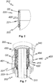
- Figure 2 shows an enlargement of the Z-marked portion of Figure 1 .
- the mating connector 420 in the form of a circumferential groove and the sealing element DE in the form of an O-ring can be clearly seen. Due to the illustrated positioning of the sealing element DE, the front part 200 and the drive part 300 can be particularly advantageously connected airtight with only one sealing element DE, which is also easily accessible for maintenance, so that no compressed air can escape uncontrolled from the injector 100.
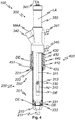
- FIG. 10 shows a perspective drawing of the injector 100 from FIG Figure 1 .
- the drive part 300 can be pushed into the front part 200 along the longitudinal axis LA.
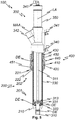
- FIG. 11 shows a longitudinal sectional drawing of the injector 100 from FIG Figure 1 wherein the front part 200 and the drive part 300 are fixed to one another along the longitudinal axis LA by the connecting device 400.
- the piston 310 is in a filling position.
- compressed air can be supplied to a mold (not shown) connected to the mouthpiece 210 of the injector 100 via a compressed air connection 340.
- This flows through the gap between the front part 200 and the inner tube 330 to its end facing the mouthpiece 210, where the compressed air is guided through a number of nozzle bores 333 into the mouthpiece 210 and thus into a cavity of the mold.
- plastic particles are sucked in through the material connection 342 from a material silo (not shown) and transported with it into the cavity.
- the material connection 342 can have a material connection axis MAA which is inclined with respect to the longitudinal axis LA. A particularly simple and compact design of the injector 100 is thereby possible.
- the nozzle 331 is easily accessible in the split state of the injector 100, it can be exchanged with little effort. This is necessary, for example, if the air consumption of the injector is to be adapted to the material to be processed.
- the same drive part 300 can therefore - equipped with several interchangeable nozzles - be used optimally for different plastics (with different densities).
- FIG. 11 shows a longitudinal sectional drawing of the injector 100 from FIG Figure 1 wherein the front part 200 and the drive part 300 are fixed to one another along the longitudinal axis LA by the connecting device 400.
- the piston 310 is in a closed position in which the bore 211 of the mouthpiece 210 is closed by the piston 310.
- the piston 310 can have at least one sealing element DE, for example an O-ring.
- the piston 310 In the closed position, foaming plastic is prevented from penetrating into the injector 100 in a form (not shown) connected to the mouthpiece 210.
- the piston 310 In the closed position, the piston 310 is advantageously flush with the side of the mouthpiece 310 facing the mold. Otherwise, the protruding or recessed protrusion of the piston 310 on the foamed molded part could result in an undesired imprint of the same.
- the lengths of the front part 200, piston 310 and piston rod 311 along the longitudinal axis LA must be precisely matched to one another.
- the front part 200 shown has a ring nut 222 which secures the position of the adapter 221 on the front part 200 along the longitudinal axis LA.
- the position of the piston 310 along the longitudinal axis LA can be adjusted and fixed, for example, by a lock nut 313. Both parts can therefore be preset to a reference dimension at the factory. A particularly tight tolerance of the individual part dimensions is therefore not necessary, which has an effect in favor of manufacturing costs. It goes without saying that if the component dimensions are tolerated sufficiently close, the ring nut 222 and the lock nut 313 could be dispensed with, and in particular all components could be screwed tightly against one another. However, this would drive up the manufacturing costs unnecessarily.
- FIG. 10 shows a perspective drawing of the injector 100 from FIG Figure 4 .
- FIG Figure 7 shows an enlargement of the portion of FIG Figure 6 .
- the frame element 450 shown is shaped on its inside in such a way that, in the operating position shown, it radially fixes the spherical connectors 410 in the groove-shaped mating connector 420 of the adapter 222. If the frame element 450 shown counteracts the force of the spring element 430 Moved toward the drive part 300 into the assembly position, the connectors 410 can move radially outward in a recess 451 running around the inside of the frame element 450. As a result, the connectors 410 are no longer fixed in the mating connectors 420, so that the front part 200 can be pulled out of the connecting device 400 and thus separated from the drive part 300.
- Figure 8 shows a schematic representation of a form F equipped with front parts 200 according to the invention (labeled only as an example). Furthermore, the form F has a number of ejector rods AS (labeled only as an example), so that the space for mounting drive parts (not shown) to the Front parts 200 is very cramped.
- Figure 9 shows a schematic representation of the form F from Figure 8 , wherein the form F is equipped with injectors 100 according to the invention (only labeled as an example).
- the drive parts 300 of the injectors 100 can be rotated about the longitudinal axes of the front parts 200 of the injectors 100.
- feed lines (not shown) for plastic particles can easily be connected to the material connections 342 of the drive parts 300 despite the confined space, for example due to ejector rods AS and / or further injectors.
- FIG. 10 4 shows a schematic representation of a method 500 according to the invention.
- the method 500 comprises equipping 510 of a number of molds F with, in particular according to the invention, front parts 200 of injectors 100.
- An attachment 520 of drive parts 300 to the front parts 200 on at least one mold F can then be performed take place in order to provide injectors 100 according to the invention on the form F.
- the drive parts 300 can each experience an alignment 530 about a longitudinal axis LA of the front parts 200. Alignment 530 facilitates subsequent connection 550 of feed lines, for example for compressed air and / or plastic particles, to drive parts 300.
- the aforementioned preparatory steps can be followed by the production of molded parts in the form F.
- the production includes, for example, filling 560 of the form F with plastic particles through the injectors 100; a closing 565 of the filling openings of the form F, to which the injectors 100 are connected, by pistons 310 of the injectors 100; a foaming 570 of the plastic particles in the form F and an ejection 580 of the foamed plastic molding from the form F, for example by ejector rods AS and / or the pistons 310 of the injectors 100.
- the filling 560, closing 565, foaming 570 and ejecting 580 can be repeated until the desired amount of molded parts with the form F is produced is.
- the drive parts 300 can be detached 540 from the front parts 200 connected to the mold F. This can be followed by fastening 520 the drive parts 300 to the front parts 200 connected to the further mold F, which can be followed by the further method steps for the mold F.
- a variety of shapes F can be used with a small number of drive parts 300.
- the front parts 200 and / or drive parts 300 separated from one another can be serviced 590, for example with cleaning and / or checking and / or exchanging wear parts.
- wearing parts are advantageously arranged in such a way that they are easily accessible when the front parts 200 and drive parts 300 of the injectors 100 are separated from one another.
- Figure 11 shows a schematic representation of a production system 600 according to the invention.
- the production system 600 shown for producing molded parts from plastic in a number of molds F with at least one automatic foaming machine 601 comprises a loading station 620 for loading 510 the molds F with, in particular according to the invention, front parts 200.
- the production plant 600 shown also includes a set-up station 610 for fastening 520 drive parts 300 to the front parts attached to at least one of the molds F to form injectors 100 according to the invention and / or for detaching 540 the drive parts 300 from the front parts 200.
- the illustrated production plant 600 includes a transport system 630 for transporting the molds F, for example in the form of a rail system connecting the foaming machine 601, the setup station 610 and / or the loading station 620 with a number of transport robots guided thereon.
- a transport system 630 for transporting the molds F, for example in the form of a rail system connecting the foaming machine 601, the setup station 610 and / or the loading station 620 with a number of transport robots guided thereon.
Landscapes
- Injection Moulding Of Plastics Or The Like (AREA)
Priority Applications (2)
| Application Number | Priority Date | Filing Date | Title |
|---|---|---|---|
| EP17167454.2A EP3392013B1 (de) | 2017-04-21 | 2017-04-21 | Injektor, vorderteil für einen injektor, verfahren und produktionsanlage zur herstellung von formteilen aus kunststoff |
| DK17167454.2T DK3392013T3 (da) | 2017-04-21 | 2017-04-21 | Injektor, forreste del til en injektor, metode og produktionslinie til fremstilling af støbte plasticdele |
Applications Claiming Priority (1)
| Application Number | Priority Date | Filing Date | Title |
|---|---|---|---|
| EP17167454.2A EP3392013B1 (de) | 2017-04-21 | 2017-04-21 | Injektor, vorderteil für einen injektor, verfahren und produktionsanlage zur herstellung von formteilen aus kunststoff |
Publications (2)
| Publication Number | Publication Date |
|---|---|
| EP3392013A1 EP3392013A1 (de) | 2018-10-24 |
| EP3392013B1 true EP3392013B1 (de) | 2020-08-26 |
Family
ID=58638684
Family Applications (1)
| Application Number | Title | Priority Date | Filing Date |
|---|---|---|---|
| EP17167454.2A Active EP3392013B1 (de) | 2017-04-21 | 2017-04-21 | Injektor, vorderteil für einen injektor, verfahren und produktionsanlage zur herstellung von formteilen aus kunststoff |
Country Status (2)
| Country | Link |
|---|---|
| EP (1) | EP3392013B1 (da) |
| DK (1) | DK3392013T3 (da) |
Families Citing this family (1)
| Publication number | Priority date | Publication date | Assignee | Title |
|---|---|---|---|---|
| CA3155564A1 (en) * | 2019-10-11 | 2021-04-15 | Gyroscope Therapeutics Limited | Dose clip assembly for syringe |
Family Cites Families (8)
| Publication number | Priority date | Publication date | Assignee | Title |
|---|---|---|---|---|
| CH398953A (de) * | 1962-01-30 | 1966-03-15 | Eth Albert Rossel Dipl Ing | Verfahren und Vorrichtung zum Füllen von in Formmaschinen angeordneten Vielfachformen |
| DE2141373A1 (de) | 1971-08-18 | 1973-03-01 | Nymphius Kg Heinrich | Fuellinjektor mit auswerfer |
| JPS59188415A (ja) * | 1983-04-12 | 1984-10-25 | Kanto Kiko Kk | 金型用付属設備筒状体の取り付け装置 |
| JPH0780193B2 (ja) * | 1989-12-31 | 1995-08-30 | 東洋機械金属株式会社 | 発泡成形機用分割型フィラー |
| JPH0636910Y2 (ja) * | 1991-11-20 | 1994-09-28 | 廣司 可児 | 発泡プラスチックビーズ用充填機 |
| JPH09174587A (ja) * | 1995-12-28 | 1997-07-08 | Daisen Kogyo:Kk | 発泡成形機における原料ホッパと充填フィーダとの接続機構 |
| JP3031914B1 (ja) * | 1999-06-18 | 2000-04-10 | 有限会社ベステック | 発泡プラスチック成形における多用途充填機 |
| DE102009024278B4 (de) | 2009-06-05 | 2012-11-29 | Nico Erlenbach | Füllvorrichtung |
-
2017
- 2017-04-21 DK DK17167454.2T patent/DK3392013T3/da active
- 2017-04-21 EP EP17167454.2A patent/EP3392013B1/de active Active
Non-Patent Citations (1)
| Title |
|---|
| None * |
Also Published As
| Publication number | Publication date |
|---|---|
| DK3392013T3 (da) | 2020-11-23 |
| EP3392013A1 (de) | 2018-10-24 |
Similar Documents
| Publication | Publication Date | Title |
|---|---|---|
| EP2976160B1 (de) | Spritzsystem, beschichtungsanlage sowie verfahren zum beschichten | |
| EP2486985B1 (de) | Farbspritzpistole mit einem Grundkörper und einer auswechselbaren Farbleiteinrichtung | |
| DE3249951C2 (da) | ||
| EP3930980B1 (de) | Vorrichtung zur anspritzung von kunststoffelementen an oberflächen eines halbzeugs | |
| EP2589481A1 (de) | Vorrichtung zur fortlaufenden Herstellung eines Verbundrohres mit Verbindungs-Muffe | |
| DE102009034715A1 (de) | Spritzgusswerkzeug, Verfahren zum Spritzgießen eines Spritzgussbauteils sowie Verschluss- und/oder Anschlusseinrichtung eines Spritzpistolenfarbbechers | |
| EP3227594B1 (de) | Schnellwechseldüse, zugehöriges düsen-schnellwechselsystem und zugehöriges applikationssystem | |
| EP2279849A2 (de) | Schnellwechselmechanismus für Bodenteile | |
| DE102014107512B4 (de) | Blasformeinrichtung mit vorspannbarer Befestigung für Blasformen | |
| DE69200315T3 (de) | Vorrichtung und Verfahren zum Wieder-im-Form-bringen von Behältern. | |
| WO2011015933A2 (de) | Einrichtung zur beschichtung der innenoberfläche von metallrohren und verfahren zum herstellen des thermoplastüberzugs | |
| DE2429223A1 (de) | Kontinuierlich arbeitende rotationsvorrichtung zum formblasen von kunststoffhohlkoerpern | |
| EP3392013B1 (de) | Injektor, vorderteil für einen injektor, verfahren und produktionsanlage zur herstellung von formteilen aus kunststoff | |
| DE69525199T2 (de) | Formvorrichtung | |
| DE102017213955A1 (de) | Auswerfersystem zum Auswerfen eines Formteils aus einem Formnest einer Form | |
| DE4207375C2 (de) | Kupplung für das zeitweise koaxiale Verbinden von Einzelrohren | |
| DE102005059130B4 (de) | Vorrichtung zum Spritzgießen von Formteilen | |
| EP2324988A2 (de) | Auswerfervorrichtung für Thermoformwerkzeuge | |
| EP3153296B1 (de) | Spritzkopf für eine vorrichtung zur herstellung eines verbundrohres | |
| DE102014019722A1 (de) | Blasformeinrichtung mit vorspannbarer Befestigung für Blasformen | |
| DE102014102448A1 (de) | Vorrichtung und Verfahren zum Umformen, insbesondere Fließpressen, von metallischen Werkstücken | |
| DE29612132U1 (de) | Form zur Herstellung von Kunststoffformteilen, insbesondere hinterschäumten Formteilen aus Polyurethan | |
| DE3904838A1 (de) | Rohrverbindung, insbesondere fuer kunststoffrohre und -schlaeuche oder dergleichen sowie verfahren und vorrichtung zu ihrer herstellung | |
| WO2010046189A1 (de) | Schnellwechselsystem für reckstangen | |
| DE102010040317A1 (de) | Produktionseinrichtung für Kunststoffwellrohre mit reduzierten Werkzeugwechselzeiten |
Legal Events
| Date | Code | Title | Description |
|---|---|---|---|
| PUAI | Public reference made under article 153(3) epc to a published international application that has entered the european phase |
Free format text: ORIGINAL CODE: 0009012 |
|
| STAA | Information on the status of an ep patent application or granted ep patent |
Free format text: STATUS: THE APPLICATION HAS BEEN PUBLISHED |
|
| STAA | Information on the status of an ep patent application or granted ep patent |
Free format text: STATUS: REQUEST FOR EXAMINATION WAS MADE |
|
| AK | Designated contracting states |
Kind code of ref document: A1 Designated state(s): AL AT BE BG CH CY CZ DE DK EE ES FI FR GB GR HR HU IE IS IT LI LT LU LV MC MK MT NL NO PL PT RO RS SE SI SK SM TR |
|
| AX | Request for extension of the european patent |
Extension state: BA ME |
|
| 17P | Request for examination filed |
Effective date: 20180920 |
|
| RBV | Designated contracting states (corrected) |
Designated state(s): AL AT BE BG CH CY CZ DE DK EE ES FI FR GB GR HR HU IE IS IT LI LT LU LV MC MK MT NL NO PL PT RO RS SE SI SK SM TR |
|
| GRAP | Despatch of communication of intention to grant a patent |
Free format text: ORIGINAL CODE: EPIDOSNIGR1 |
|
| STAA | Information on the status of an ep patent application or granted ep patent |
Free format text: STATUS: GRANT OF PATENT IS INTENDED |
|
| INTG | Intention to grant announced |
Effective date: 20200608 |
|
| GRAS | Grant fee paid |
Free format text: ORIGINAL CODE: EPIDOSNIGR3 |
|
| GRAA | (expected) grant |
Free format text: ORIGINAL CODE: 0009210 |
|
| STAA | Information on the status of an ep patent application or granted ep patent |
Free format text: STATUS: THE PATENT HAS BEEN GRANTED |
|
| AK | Designated contracting states |
Kind code of ref document: B1 Designated state(s): AL AT BE BG CH CY CZ DE DK EE ES FI FR GB GR HR HU IE IS IT LI LT LU LV MC MK MT NL NO PL PT RO RS SE SI SK SM TR |
|
| REG | Reference to a national code |
Ref country code: GB Ref legal event code: FG4D Free format text: NOT ENGLISH |
|
| REG | Reference to a national code |
Ref country code: CH Ref legal event code: EP |
|
| REG | Reference to a national code |
Ref country code: AT Ref legal event code: REF Ref document number: 1305939 Country of ref document: AT Kind code of ref document: T Effective date: 20200915 |
|
| REG | Reference to a national code |
Ref country code: IE Ref legal event code: FG4D Free format text: LANGUAGE OF EP DOCUMENT: GERMAN |
|
| REG | Reference to a national code |
Ref country code: DE Ref legal event code: R096 Ref document number: 502017006886 Country of ref document: DE |
|
| REG | Reference to a national code |
Ref country code: DK Ref legal event code: T3 Effective date: 20201118 |
|
| REG | Reference to a national code |
Ref country code: LT Ref legal event code: MG4D |
|
| PG25 | Lapsed in a contracting state [announced via postgrant information from national office to epo] |
Ref country code: NO Free format text: LAPSE BECAUSE OF FAILURE TO SUBMIT A TRANSLATION OF THE DESCRIPTION OR TO PAY THE FEE WITHIN THE PRESCRIBED TIME-LIMIT Effective date: 20201126 Ref country code: GR Free format text: LAPSE BECAUSE OF FAILURE TO SUBMIT A TRANSLATION OF THE DESCRIPTION OR TO PAY THE FEE WITHIN THE PRESCRIBED TIME-LIMIT Effective date: 20201127 Ref country code: HR Free format text: LAPSE BECAUSE OF FAILURE TO SUBMIT A TRANSLATION OF THE DESCRIPTION OR TO PAY THE FEE WITHIN THE PRESCRIBED TIME-LIMIT Effective date: 20200826 Ref country code: PT Free format text: LAPSE BECAUSE OF FAILURE TO SUBMIT A TRANSLATION OF THE DESCRIPTION OR TO PAY THE FEE WITHIN THE PRESCRIBED TIME-LIMIT Effective date: 20201228 Ref country code: FI Free format text: LAPSE BECAUSE OF FAILURE TO SUBMIT A TRANSLATION OF THE DESCRIPTION OR TO PAY THE FEE WITHIN THE PRESCRIBED TIME-LIMIT Effective date: 20200826 Ref country code: SE Free format text: LAPSE BECAUSE OF FAILURE TO SUBMIT A TRANSLATION OF THE DESCRIPTION OR TO PAY THE FEE WITHIN THE PRESCRIBED TIME-LIMIT Effective date: 20200826 Ref country code: LT Free format text: LAPSE BECAUSE OF FAILURE TO SUBMIT A TRANSLATION OF THE DESCRIPTION OR TO PAY THE FEE WITHIN THE PRESCRIBED TIME-LIMIT Effective date: 20200826 Ref country code: BG Free format text: LAPSE BECAUSE OF FAILURE TO SUBMIT A TRANSLATION OF THE DESCRIPTION OR TO PAY THE FEE WITHIN THE PRESCRIBED TIME-LIMIT Effective date: 20201126 |
|
| REG | Reference to a national code |
Ref country code: NL Ref legal event code: MP Effective date: 20200826 |
|
| PG25 | Lapsed in a contracting state [announced via postgrant information from national office to epo] |
Ref country code: LV Free format text: LAPSE BECAUSE OF FAILURE TO SUBMIT A TRANSLATION OF THE DESCRIPTION OR TO PAY THE FEE WITHIN THE PRESCRIBED TIME-LIMIT Effective date: 20200826 Ref country code: NL Free format text: LAPSE BECAUSE OF FAILURE TO SUBMIT A TRANSLATION OF THE DESCRIPTION OR TO PAY THE FEE WITHIN THE PRESCRIBED TIME-LIMIT Effective date: 20200826 Ref country code: PL Free format text: LAPSE BECAUSE OF FAILURE TO SUBMIT A TRANSLATION OF THE DESCRIPTION OR TO PAY THE FEE WITHIN THE PRESCRIBED TIME-LIMIT Effective date: 20200826 Ref country code: RS Free format text: LAPSE BECAUSE OF FAILURE TO SUBMIT A TRANSLATION OF THE DESCRIPTION OR TO PAY THE FEE WITHIN THE PRESCRIBED TIME-LIMIT Effective date: 20200826 Ref country code: IS Free format text: LAPSE BECAUSE OF FAILURE TO SUBMIT A TRANSLATION OF THE DESCRIPTION OR TO PAY THE FEE WITHIN THE PRESCRIBED TIME-LIMIT Effective date: 20201226 |
|
| PG25 | Lapsed in a contracting state [announced via postgrant information from national office to epo] |
Ref country code: EE Free format text: LAPSE BECAUSE OF FAILURE TO SUBMIT A TRANSLATION OF THE DESCRIPTION OR TO PAY THE FEE WITHIN THE PRESCRIBED TIME-LIMIT Effective date: 20200826 Ref country code: SM Free format text: LAPSE BECAUSE OF FAILURE TO SUBMIT A TRANSLATION OF THE DESCRIPTION OR TO PAY THE FEE WITHIN THE PRESCRIBED TIME-LIMIT Effective date: 20200826 Ref country code: RO Free format text: LAPSE BECAUSE OF FAILURE TO SUBMIT A TRANSLATION OF THE DESCRIPTION OR TO PAY THE FEE WITHIN THE PRESCRIBED TIME-LIMIT Effective date: 20200826 Ref country code: CZ Free format text: LAPSE BECAUSE OF FAILURE TO SUBMIT A TRANSLATION OF THE DESCRIPTION OR TO PAY THE FEE WITHIN THE PRESCRIBED TIME-LIMIT Effective date: 20200826 |
|
| REG | Reference to a national code |
Ref country code: DE Ref legal event code: R097 Ref document number: 502017006886 Country of ref document: DE |
|
| PG25 | Lapsed in a contracting state [announced via postgrant information from national office to epo] |
Ref country code: ES Free format text: LAPSE BECAUSE OF FAILURE TO SUBMIT A TRANSLATION OF THE DESCRIPTION OR TO PAY THE FEE WITHIN THE PRESCRIBED TIME-LIMIT Effective date: 20200826 Ref country code: AL Free format text: LAPSE BECAUSE OF FAILURE TO SUBMIT A TRANSLATION OF THE DESCRIPTION OR TO PAY THE FEE WITHIN THE PRESCRIBED TIME-LIMIT Effective date: 20200826 |
|
| PG25 | Lapsed in a contracting state [announced via postgrant information from national office to epo] |
Ref country code: SK Free format text: LAPSE BECAUSE OF FAILURE TO SUBMIT A TRANSLATION OF THE DESCRIPTION OR TO PAY THE FEE WITHIN THE PRESCRIBED TIME-LIMIT Effective date: 20200826 |
|
| PLBE | No opposition filed within time limit |
Free format text: ORIGINAL CODE: 0009261 |
|
| STAA | Information on the status of an ep patent application or granted ep patent |
Free format text: STATUS: NO OPPOSITION FILED WITHIN TIME LIMIT |
|
| 26N | No opposition filed |
Effective date: 20210527 |
|
| PG25 | Lapsed in a contracting state [announced via postgrant information from national office to epo] |
Ref country code: SI Free format text: LAPSE BECAUSE OF FAILURE TO SUBMIT A TRANSLATION OF THE DESCRIPTION OR TO PAY THE FEE WITHIN THE PRESCRIBED TIME-LIMIT Effective date: 20200826 |
|
| PG25 | Lapsed in a contracting state [announced via postgrant information from national office to epo] |
Ref country code: MC Free format text: LAPSE BECAUSE OF FAILURE TO SUBMIT A TRANSLATION OF THE DESCRIPTION OR TO PAY THE FEE WITHIN THE PRESCRIBED TIME-LIMIT Effective date: 20200826 |
|
| GBPC | Gb: european patent ceased through non-payment of renewal fee |
Effective date: 20210421 |
|
| PG25 | Lapsed in a contracting state [announced via postgrant information from national office to epo] |
Ref country code: LU Free format text: LAPSE BECAUSE OF NON-PAYMENT OF DUE FEES Effective date: 20210421 |
|
| REG | Reference to a national code |
Ref country code: BE Ref legal event code: MM Effective date: 20210430 |
|
| PG25 | Lapsed in a contracting state [announced via postgrant information from national office to epo] |
Ref country code: LI Free format text: LAPSE BECAUSE OF NON-PAYMENT OF DUE FEES Effective date: 20210430 Ref country code: CH Free format text: LAPSE BECAUSE OF NON-PAYMENT OF DUE FEES Effective date: 20210430 Ref country code: GB Free format text: LAPSE BECAUSE OF NON-PAYMENT OF DUE FEES Effective date: 20210421 |
|
| PG25 | Lapsed in a contracting state [announced via postgrant information from national office to epo] |
Ref country code: IE Free format text: LAPSE BECAUSE OF NON-PAYMENT OF DUE FEES Effective date: 20210421 |
|
| PG25 | Lapsed in a contracting state [announced via postgrant information from national office to epo] |
Ref country code: IS Free format text: LAPSE BECAUSE OF FAILURE TO SUBMIT A TRANSLATION OF THE DESCRIPTION OR TO PAY THE FEE WITHIN THE PRESCRIBED TIME-LIMIT Effective date: 20201226 |
|
| PG25 | Lapsed in a contracting state [announced via postgrant information from national office to epo] |
Ref country code: BE Free format text: LAPSE BECAUSE OF NON-PAYMENT OF DUE FEES Effective date: 20210430 |
|
| REG | Reference to a national code |
Ref country code: AT Ref legal event code: MM01 Ref document number: 1305939 Country of ref document: AT Kind code of ref document: T Effective date: 20220421 |
|
| P01 | Opt-out of the competence of the unified patent court (upc) registered |
Effective date: 20230515 |
|
| PG25 | Lapsed in a contracting state [announced via postgrant information from national office to epo] |
Ref country code: CY Free format text: LAPSE BECAUSE OF FAILURE TO SUBMIT A TRANSLATION OF THE DESCRIPTION OR TO PAY THE FEE WITHIN THE PRESCRIBED TIME-LIMIT Effective date: 20200826 |
|
| PG25 | Lapsed in a contracting state [announced via postgrant information from national office to epo] |
Ref country code: HU Free format text: LAPSE BECAUSE OF FAILURE TO SUBMIT A TRANSLATION OF THE DESCRIPTION OR TO PAY THE FEE WITHIN THE PRESCRIBED TIME-LIMIT; INVALID AB INITIO Effective date: 20170421 Ref country code: AT Free format text: LAPSE BECAUSE OF NON-PAYMENT OF DUE FEES Effective date: 20220421 |
|
| PG25 | Lapsed in a contracting state [announced via postgrant information from national office to epo] |
Ref country code: MK Free format text: LAPSE BECAUSE OF FAILURE TO SUBMIT A TRANSLATION OF THE DESCRIPTION OR TO PAY THE FEE WITHIN THE PRESCRIBED TIME-LIMIT Effective date: 20200826 |
|
| PG25 | Lapsed in a contracting state [announced via postgrant information from national office to epo] |
Ref country code: MT Free format text: LAPSE BECAUSE OF FAILURE TO SUBMIT A TRANSLATION OF THE DESCRIPTION OR TO PAY THE FEE WITHIN THE PRESCRIBED TIME-LIMIT Effective date: 20200826 |
|
| PG25 | Lapsed in a contracting state [announced via postgrant information from national office to epo] |
Ref country code: TR Free format text: LAPSE BECAUSE OF FAILURE TO SUBMIT A TRANSLATION OF THE DESCRIPTION OR TO PAY THE FEE WITHIN THE PRESCRIBED TIME-LIMIT Effective date: 20200826 |
|
| PGFP | Annual fee paid to national office [announced via postgrant information from national office to epo] |
Ref country code: DE Payment date: 20251020 Year of fee payment: 9 |
|
| PGFP | Annual fee paid to national office [announced via postgrant information from national office to epo] |
Ref country code: DK Payment date: 20251030 Year of fee payment: 9 Ref country code: IT Payment date: 20251029 Year of fee payment: 9 |
|
| PGFP | Annual fee paid to national office [announced via postgrant information from national office to epo] |
Ref country code: FR Payment date: 20251030 Year of fee payment: 9 |