EP3396093A1 - Système d'aération automatique - Google Patents
Système d'aération automatique Download PDFInfo
- Publication number
- EP3396093A1 EP3396093A1 EP18169813.5A EP18169813A EP3396093A1 EP 3396093 A1 EP3396093 A1 EP 3396093A1 EP 18169813 A EP18169813 A EP 18169813A EP 3396093 A1 EP3396093 A1 EP 3396093A1
- Authority
- EP
- European Patent Office
- Prior art keywords
- window
- base
- door
- latch
- fixedly connected
- Prior art date
- Legal status (The legal status is an assumption and is not a legal conclusion. Google has not performed a legal analysis and makes no representation as to the accuracy of the status listed.)
- Withdrawn
Links
Images




Classifications
-
- E—FIXED CONSTRUCTIONS
- E05—LOCKS; KEYS; WINDOW OR DOOR FITTINGS; SAFES
- E05F—DEVICES FOR MOVING WINGS INTO OPEN OR CLOSED POSITION; CHECKS FOR WINGS; WING FITTINGS NOT OTHERWISE PROVIDED FOR, CONCERNED WITH THE FUNCTIONING OF THE WING
- E05F15/00—Power-operated mechanisms for wings
- E05F15/60—Power-operated mechanisms for wings using electrical actuators
- E05F15/603—Power-operated mechanisms for wings using electrical actuators using rotary electromotors
- E05F15/611—Power-operated mechanisms for wings using electrical actuators using rotary electromotors for swinging wings
-
- E—FIXED CONSTRUCTIONS
- E05—LOCKS; KEYS; WINDOW OR DOOR FITTINGS; SAFES
- E05C—BOLTS OR FASTENING DEVICES FOR WINGS, SPECIALLY FOR DOORS OR WINDOWS
- E05C17/00—Devices for holding wings open; Devices for limiting opening of wings or for holding wings open by a movable member extending between frame and wing; Braking devices, stops or buffers, combined therewith
- E05C17/02—Devices for holding wings open; Devices for limiting opening of wings or for holding wings open by a movable member extending between frame and wing; Braking devices, stops or buffers, combined therewith by mechanical means
- E05C17/46—Devices for holding wings open; Devices for limiting opening of wings or for holding wings open by a movable member extending between frame and wing; Braking devices, stops or buffers, combined therewith by mechanical means in which the wing or a member fixed thereon is engaged by a movable fastening member in a fixed position; in which a movable fastening member mounted on the wing engages a stationary member
- E05C17/50—Devices for holding wings open; Devices for limiting opening of wings or for holding wings open by a movable member extending between frame and wing; Braking devices, stops or buffers, combined therewith by mechanical means in which the wing or a member fixed thereon is engaged by a movable fastening member in a fixed position; in which a movable fastening member mounted on the wing engages a stationary member comprising a single pivoted securing member
-
- E—FIXED CONSTRUCTIONS
- E05—LOCKS; KEYS; WINDOW OR DOOR FITTINGS; SAFES
- E05Y—INDEXING SCHEME ASSOCIATED WITH SUBCLASSES E05D AND E05F, RELATING TO CONSTRUCTION ELEMENTS, ELECTRIC CONTROL, POWER SUPPLY, POWER SIGNAL OR TRANSMISSION, USER INTERFACES, MOUNTING OR COUPLING, DETAILS, ACCESSORIES, AUXILIARY OPERATIONS NOT OTHERWISE PROVIDED FOR, APPLICATION THEREOF
- E05Y2201/00—Constructional elements; Accessories therefor
- E05Y2201/20—Brakes; Disengaging means; Holders; Stops; Valves; Accessories therefor
- E05Y2201/218—Holders
-
- E—FIXED CONSTRUCTIONS
- E05—LOCKS; KEYS; WINDOW OR DOOR FITTINGS; SAFES
- E05Y—INDEXING SCHEME ASSOCIATED WITH SUBCLASSES E05D AND E05F, RELATING TO CONSTRUCTION ELEMENTS, ELECTRIC CONTROL, POWER SUPPLY, POWER SIGNAL OR TRANSMISSION, USER INTERFACES, MOUNTING OR COUPLING, DETAILS, ACCESSORIES, AUXILIARY OPERATIONS NOT OTHERWISE PROVIDED FOR, APPLICATION THEREOF
- E05Y2600/00—Mounting or coupling arrangements for elements provided for in this subclass
- E05Y2600/10—Adjustable
-
- E—FIXED CONSTRUCTIONS
- E05—LOCKS; KEYS; WINDOW OR DOOR FITTINGS; SAFES
- E05Y—INDEXING SCHEME ASSOCIATED WITH SUBCLASSES E05D AND E05F, RELATING TO CONSTRUCTION ELEMENTS, ELECTRIC CONTROL, POWER SUPPLY, POWER SIGNAL OR TRANSMISSION, USER INTERFACES, MOUNTING OR COUPLING, DETAILS, ACCESSORIES, AUXILIARY OPERATIONS NOT OTHERWISE PROVIDED FOR, APPLICATION THEREOF
- E05Y2800/00—Details, accessories and auxiliary operations not otherwise provided for
- E05Y2800/70—Retrofitting of elements
-
- E—FIXED CONSTRUCTIONS
- E05—LOCKS; KEYS; WINDOW OR DOOR FITTINGS; SAFES
- E05Y—INDEXING SCHEME ASSOCIATED WITH SUBCLASSES E05D AND E05F, RELATING TO CONSTRUCTION ELEMENTS, ELECTRIC CONTROL, POWER SUPPLY, POWER SIGNAL OR TRANSMISSION, USER INTERFACES, MOUNTING OR COUPLING, DETAILS, ACCESSORIES, AUXILIARY OPERATIONS NOT OTHERWISE PROVIDED FOR, APPLICATION THEREOF
- E05Y2800/00—Details, accessories and auxiliary operations not otherwise provided for
- E05Y2800/74—Specific positions
- E05Y2800/75—Specific positions intermediate
-
- E—FIXED CONSTRUCTIONS
- E05—LOCKS; KEYS; WINDOW OR DOOR FITTINGS; SAFES
- E05Y—INDEXING SCHEME ASSOCIATED WITH SUBCLASSES E05D AND E05F, RELATING TO CONSTRUCTION ELEMENTS, ELECTRIC CONTROL, POWER SUPPLY, POWER SIGNAL OR TRANSMISSION, USER INTERFACES, MOUNTING OR COUPLING, DETAILS, ACCESSORIES, AUXILIARY OPERATIONS NOT OTHERWISE PROVIDED FOR, APPLICATION THEREOF
- E05Y2900/00—Application of doors, windows, wings or fittings thereof
- E05Y2900/10—Application of doors, windows, wings or fittings thereof for buildings or parts thereof
- E05Y2900/13—Type of wing
- E05Y2900/148—Windows
Definitions
- the invention relates to an automatic ventilation system with a motor drive device for transferring a pivotable about a vertical axis window or door leaf in a ventilation position.
- Out DE 10 2015 104 047 A1 is a lock for locking a tilt and / or swivel window sash known in a ventilation position.
- the lock has at least one magnet, which prevents an arrested in the ventilation position window sash not, for example, by drafts, accidentally strikes.
- the lock on a bolt which is adapted to be fastened by means of a fastener to a window frame.
- the bolt is fastened to the window frame in such a way that the window sash can be opened and closed undisturbed and a bolt mounted rotatably on the bolt can be moved into the swiveling range of the window sash.
- EP 3 073 040 A2 also discloses such a device. In this document, it is proposed to open a window sash for a ventilation operation to an opening width of 12 mm.
- the door or window lock has a holder which can be fixedly mounted on a flat surface next to a door or window sash of a door or window.
- the door or window lock has a first pivot arm pivotable relative to the bracket and a second pivot arm pivotally connected to the end of the first pivot arm and movable to secure the door or window to a use position in which it fully opens the door - or window sash prevented.
- Out DE 741 63 73 U is a locking bolt for partially open tilt windows known.
- the locking latch has a locking frame to be rotatably mounted on the fixed window frame, which has one or two recesses, one of which engages over a side frame of the tilting window in the rotated locking position and locks it in this position.
- this device does not allow to effect a limitation of the opening width before opening the window sash, whereby the locking bar is not available, or only with very considerable effort, in particular with regard to automated ventilation.
- Out DE 1 764 109 U is a locking device for tilt and swing windows known.
- the locking device serves to lock a window when ventilating a room.
- the locking device is adapted to cooperate with a cage closure.
- One Baskülever gleich consists of a arranged on the window frame rotary handle with a locking lever and one or two by means of this rotary handle moving locking rods, which engage the top and bottom of the window floor, thus causing a locking of the window.
- the locking device has a in the path of movement of the locking bar perpendicular to the window frame close above the window frame arranged arm with a plurality of notches, in which engages the locking rod.
- this locking device is limited to windows, which are provided with a Baskülever gleich.
- this device does not allow to effect a limitation of the opening width before opening the window sash, whereby the locking bar is not available, or only with very considerable effort, in particular with regard to automated ventilation.
- an automatic ventilation system which is characterized in that the drive device is designed to automatically open a window or a door for a ventilation process to an opening width in the range of 18 mm to 25 mm.
- the ventilation system according to the invention has the very special advantage that it automatically, for example, at predetermined time intervals or when a room air parameter measured by a sensor of the ventilation system reaches a predetermined or predefinable threshold, performs a ventilation process in which a good exchange of air is ensured, however, an unnecessary cooling of the room is effectively avoided.
- the optimum opening width in a ventilation process in which the window sash is pivoted about a vertical axis, is in the range of 18 mm to 25, in particular in the range of 19 mm to 21, very particularly 20 mm.
- the ratio of the time required for the ventilation process to the amount of air exchanged is particularly good.
- the size of the window plays a minor role in this case, because the air exchange takes place substantially over the vertical gap at the free end of the window or door leaf open to said opening width.
- the opening width is understood to mean the distance between the free end of the window sash and the part of the window frame on which the free end rests in the closed state.
- the above-mentioned opening width in particular an opening width of 20 mm, in particular also has the advantage that a good "air intake” takes place in interaction with the usual space heating.
- a much larger opening width than 21 mm, in particular 25 mm, has the disadvantage that in winter the temperature drop in the room is too large, so that there is a risk that persons in the room freeze during the ventilation process until the room after the ventilation process has warmed up again.
- a greater opening width than 25 mm in particular already 20 mm or 21 mm, has the disadvantage that a greater possibility of attack for burglars is offered, for example, to set crowbars.
- a larger opening width 25 mm, in particular 20 mm or 21 mm the disadvantage that it can be easily recognized from the outside that a window is not completely closed, but is apparently in ventilation position.
- An opening width in the range of 18 mm to 25 mm, in particular in the range of 19 mm to 21 mm, in particular 20 mm, has in particular the very special advantage that the heels and folds present in conventional heat protection windows intermesh when closed such an opening width form a kind of labyrinth, which is too narrow for a screwdriver or a crowbar; unlike larger opening widths. This ensures that even in the open position a good burglary protection is given.
- the drive device is preferably designed to automatically close the window or the door for ending the ventilation process.
- a control device of the ventilation system automatically opens a window or door in certain or predeterminable time intervals for each specific or predeterminable ventilation period on said opening width and then closes again and preferably also locked again.
- the entire ventilation process is preferably completely automatic and without that immediate action by a person. It is preferably at most necessary for a person to carry out actions for installation and / or basic adjustment of the ventilation system, for example for adaptation to the dimensions of the window or the door.
- the ventilation system has a sensor for measuring a room air parameter, in particular the humidity. This allows the ventilation system to transfer a window or door leaf from a closed position to a ventilation position when at least one measured room air parameter, such as humidity and / or carbon dioxide content, exceeds a predetermined or predeterminable threshold. As soon as the ventilation system detects that the room air parameter is again within a desired range, it automatically closes the window or door leaf again.
- a sensor for measuring a room air parameter in particular the humidity.
- a person triggers the automatic ventilation process, for example by a radio signal or by pressing a button directly on the device.
- the ventilation system has a device for, in particular mechanical, limiting the pivotability of a window or door leaf on the opening width.
- a device for, in particular mechanical, limiting the pivotability of a window or door leaf on the opening width advantageously prevents the arrested in the ventilation position window sash not unintentionally, for example, by wind or an unauthorized third party on the ventilation position can be further opened.
- the device for limiting the pivotability may be designed and intended to be fastened to a glazing or block frame of a window or door.
- the device for limiting the pivoting can have a rotatably mounted on a base and optionally convertible into a release position or a limiting position latch. It can be provided in a particularly advantageous manner that the distance of the bolt is adjustable to the base.
- the drive device is designed to open the window or door leaf for a ventilation process until it strikes against the latch.
- a control device automatically shuts off the drive device when the window or door leaf strikes the latch during an opening operation.
- the base of the pivotal limiting device comprises an anchoring portion adapted and adapted to be secured to a window frame of a window or door.
- the anchoring section may have through holes, through which screws which can be screwed into the frame or block frame can run.
- such an embodiment may be designed to be screwed directly to the visible inner side of a blend or block frame.
- Such a design is particularly robust and easy to assemble.
- the diaphragm or block frame is damaged on its inside, and in particular the inputs of the screw channels of the screws remain permanently visible after removal of the device for limiting the pivoting.
- the base has an anchoring portion which is adapted to be screwed to the end face of a blend or block frame and the closed window in the Interspace between the wing and the blend or block frame is arranged.
- the base has an anchoring portion which is adapted to be screwed to the end face of a blend or block frame and the closed window in the Interspace between the wing and the blend or block frame is arranged.
- inner side of a blend or block frame means the side facing an interior of a home and / or is visible from an interior of a home.
- a connecting device which connects the latch with the base, in particular with the anchoring portion of the base.
- the length of the connecting device is adjustable in order to achieve adjustability of the distance of the bolt relative to the base and so as to adjust the above-mentioned opening width can.
- At least one spacer element may be present, wherein the length of the connecting device is adjustable by inserting or omitting the spacer element.
- Particularly advantageous and versatile is an embodiment in which a plurality of spacer elements are present, wherein the length of the connecting device is adjustable in that a different number of these plurality of spacer elements can be inserted.
- a plurality of spacer elements of different lengths are provided, wherein the adjustability is achieved in that at least one of the different-length spacer elements or a plurality of spacer elements can be inserted in combination.
- the spacer element or the spacer elements can be advantageously designed, for example, as spacers.
- the use of a spacer sleeve has the particular advantage that through the passage of the spacer sleeve through a fastener, in particular a fastening screw, can run, which is described below in more detail.
- the connecting device has a first connecting element, which is fixedly connected to the base, and a second connecting element, which is fixedly connected to the latch on.
- the connecting device comprises a first connecting element which is fixedly connected to the latch, and a second connecting element which is fixedly connected to the base.
- the first connecting element has a column with a fastening element.
- the second connecting element on a sleeve in which the column is at least partially disposed on.
- a counter-fastening element which cooperates with the fastening element, is present.
- the fastening element may in particular be an internal thread arranged in the column, into which the counter-fastening element designed as a fastening screw and extending through the sleeve is screwed, whereby the first connecting element and the second connecting element are securely held together.
- the attachment is preferably, however, such that the bolt remains rotatable relative to the base in order to have to selectively dissolve this without the attachment in the release position or the limit position can.
- the sleeve may have an axial end stop inside, on which the free end of the column can abut the front side. It is particularly possible to insert between the end stop and the free end of the column, a spacer element or a plurality of spacer elements to adjust the length of the connecting device and thus the distance of the bolt to the base.
- the inserted spacer elements are preferably also disposed within the sleeve.
- the spacer elements may advantageously be designed, in particular, as spacer sleeves, so that the counter-fastening element can run through the respectively inserted spacer sleeve or the respectively inserted spacer sleeves.
- the device for limiting the pivoting is designed such that the bolt is rotatable after an adjustment relative to the base in a plane of rotation in the release position or the limit position, but not without a renewed adjustment perpendicular to the plane of rotation.
- the latch is rotatable after an adjustment operation relative to the base in a plane of rotation selectively in the release position or the limit position, without changing the distance of the bolt to the base by turning the bolt.
- the plane of rotation may be aligned parallel to an abutment surface of the base which is intended to rest on an inner side of a blind or block frame in the fastened state.
- the device for limiting the pivoting on no magnet In a particular embodiment, the device for limiting the pivoting on no magnet.
- a helical gear is present, wherein the distance of the bolt to the base by turning a threaded spindle of the helical gear is adjustable.
- the latch on a free end on a stop element which is designed and arranged to occur in the limiting position of the bolt with a window or door directly in contact.
- the stop element may for example be made of an elastic material, such as rubber or sponge rubber or silicone, and / or be formed as a buffer element. Alternatively or additionally, it is also possible that the stop element has a spring. In such an embodiment, the stop element prevents the window sash or the door leaf from causing a noise when it hits the bolt or even being damaged. This is particularly advantageous when the opening and closing of the window sash is accomplished in the context of automated ventilation of a machine.
- the stop element can be moved by means of the helical gear relative to the rest of the bolt to adjust the distance of the bolt to the base.
- a threaded spindle of the screw thread connects the latch to the base.
- Particularly robust is an embodiment in which a threaded spindle of the screw thread is operatively connected both with the bolt, and with the base.
- an embodiment of the device for limiting the pivotability is of particular advantage, in which the bolt can be transferred into the limit position even when the window is completely closed or the door is completely closed.
- a limitation of the pivoting of the window or door leaf can be made to a maximum opening width, without having to open the window immediately and without further changes of the device or the adjustment of the device are required.
- Such a design has the particular advantage that the bolt can not be transferred into its limiting position only after unlocking the window sash or even after a transfer of the window or door leaf in the ventilation position.
- a corresponding switching operation of the bolt additionally has to be carried out by an automaton only after the respective opening of the window. Rather, the bolt, as long as the user does not want to open the window or door completely, always remain in the limiting position, so that the machine can only transfer the window or door wings for ventilation in the open position and then close again without pressing the latch to have to.
- two or more pivotal limiting devices according to the invention may be mounted on a window or door.
- the ventilation system can be designed in particular as a retrofit system, can be subsequently connected to a conventional window or a conventional door.
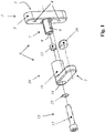
- FIG. 1 shows a first embodiment of a device according to the invention for limiting the pivoting of a window or door leaf to a maximum opening width in the range of 18 mm to 25, in particular in the range of 19 mm to 21, especially 20 mm.
- the device can advantageously be adapted individually to the respective dimensions and the geometry of the to achieve said opening width.
- the device has a latch 2 mounted on a base 1 and optionally convertible into a release position or a limiting position.
- the base 1 has an anchoring portion 3 with two through-holes 4 and is designed and intended to be attached to a glare or block frame of a window or door.
- the anchoring portion 3 has a contact surface 5 which is intended to abut against an interior of a glare or block frame which is aligned with an interior of a building. Through the through holes 4 screws can run to screw the base 1 to a blend or block frame.
- the device has a connecting device 6, which connects the latch 2 with the base 1.
- the length of the connecting device 6 is adjustable, which will be explained in detail below.
- the connecting device 6 has a first connecting element 7, which is firmly connected to the base 1.
- the first connection element 7 is designed as a column 8 with a fastening element 9 designed as an internal thread.
- the connecting device 6 also has a second connecting element 10, which is formed as a sleeve 11, in which the column 9 is axially insertable.
- a fastening screw 12 designed as a counter-fastening element 13 which extends through a stepped through hole 14 of the sleeve 11 and can be screwed into the internal thread 9 in order to connect the first connecting element 10 with the second connecting element 7.
- the passage opening is formed so that the shaft of the fastening screw 12 can be inserted through, but not the head. Between the head of the fastening screw 12 and the sleeve 11, a washer 21 is inserted.
- an axial end stop is present at which either a spacer sleeve 15 or, in omitting the spacer sleeve 15, the free end of the column 9 is applied.
- the length of the connecting device and thus the distance of the bolt 2 relative to the base 1 can be adjusted by omitting or inserting the spacer sleeve 15 or by inserting several, in particular also different lengths, spacers 15.
- the latch 2 has at its free end a stop element 16, which is designed and arranged to occur in the limiting position of the bolt 2 with a window or door directly in contact.
- FIG. 2 shows a second embodiment of an inventive device for limiting the pivoting of a window or door leaf, in which the base 1 is formed in two parts.
- this device can be advantageously adapted individually to the respective dimensions and the geometry of the, to achieve said opening width.
- the base 1 has a first anchoring portion 17, which is designed in the same way as the anchoring portion 3 of the first embodiment.
- the base 1 has a second anchoring portion 18, which is connected by first connecting bolts 19 with the first anchoring portion 17.
- the second anchoring portion 18 is adapted to be screwed by means of anchoring screws 20 to the end face of a blend or block frame, the second anchoring portion portion 18 is partially arranged in the gap between the wing and the blend or block frame with the window closed or with the door closed , In this way, it is advantageously avoided to have to damage the inside of the blend or block frame for the purpose of securing the device according to the invention.
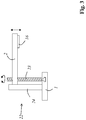
- FIG. 3 shows a third embodiment of an inventive device for limiting the pivoting of a window or door leaf, which has a helical gear 22, wherein the distance of the bolt 2 to the base 1 by turning a threaded spindle 23 of the helical gear 22 is adjustable.
- the helical gear 22 includes a linear guide 24 on which the bolt 2 is set linearly displaceable.
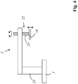
- FIG. 4 shows a fourth embodiment of an inventive device for limiting the pivoting of a window or door leaf.
- the bolt 2 connected via a support rod 25 fixed to the base 1.
- the stop member 16 of the bolt 2 by means of a helical gear 22, which includes a threaded spindle 23, are moved relative to the rest of the bolt 2 to adjust the distance of the bolt to the base.
- FIG. 5 shows a fifth embodiment of an inventive device for limiting the pivoting of a window or door leaf in a cross-sectional view.
- a threaded spindle 23 is attached on a base 1.
- the threaded spindle 23 has a non-threaded shaft 26 and a threaded portion 27 on.
- a spindle nut 28 is screwed, which can be rotated by means of a knob 29.
- a bolt 2 is guided linearly displaceable.
- a coil spring 30 is arranged, which presses the bolt 2 against the spindle nut 28.
- the coil spring 30 is arranged coaxially with the threaded spindle 23.
- the latch 2 has at its free end a stop element 16, which is designed and arranged to occur in the limiting position of the bolt 2 with a window or door directly in contact.
- the distance of the bolt (2) to the base (1) can be adjusted. If the knob 29 is rotated clockwise to the base 1, the coil spring 30 is further tensioned.
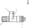
- FIG. 6 shows the fifth embodiment in a page representation.
- FIG. 7 shows a cross-sectional view of a portion of a window with a sixth embodiment of an inventive device for limiting the pivoting of a window or door sash.
- the second anchoring portion 18 of the base 1 is bolted to a blind or block frame 31 of a window.
- the second anchoring portion 18 is screwed to the circumferential inner end face of the blend or block frame 31 by means of fastening screws 32 and indeed concretely to the bottom of a groove.
- the second anchoring portion 18 is disposed in the gap with the window between the wing 33 and the blend or block frame 31 existing gap 34 and screwed there by means of the mounting screws 32.
- the first anchoring portion 17 is fixedly connected to the second anchoring portion 18 by means of first connecting bolts 19.
- the second anchoring section 18 runs around a projection 35 of the blend or block frame 31 around.
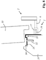
- the base 1 is shaped so that it does not hinder opening and closing of the window, which is particularly in FIG. 8 can be seen.
- connecting device 6 which connects the latch 2 with the base 1.
- the length of the connecting device 6 is adjustable in order to adjust the distance of the bolt 2 to the base 1 can.
- FIGS. 7 and 8th show a cross section through the vertically extending handle-side part of a window.
- the hinge side, on which the window is struck, is not shown in each case.
- FIG. 9 shows a window with an embodiment of an automatic ventilation system according to the invention with two devices 37 for limiting the pivoting.
- the window has a wing 33 with a sash 36.
- the wing frame 36 of the wing 33 is pivotally connected to a blend or block frame 31 and pivotable about a vertical pivot axis.
- two devices 37 according to the invention for limiting the pivoting on the handle side extending, vertical part of the blend or block frame 31 are attached.
- the latches 2 can be selectively transferred to the limiting position shown in the figure, which allows opening to an opening width of 20 mm, or a release position (not shown), which allows a complete opening of the wing 33, which in the figure Double arrows is indicated.
- a motor drive device 38 is attached to transfer the wing 2 in a ventilation position.
- the motor drive device 38 is designed to open the wing 33, in particular automatically and / or at regular time intervals, in order to open a gap to an opening width of 20 mm; namely, as far as it is possible to have the bolts 2 in their limit position.
- the motor drive device 38 automatically closes the window after each ventilation operation.
- the motor drive device 38 of the one movable between a retracted position and an extended position ram (not shown). In its retracted position, the ram obstructs a complete Close a wing 36 not. If the plunger is extended, it is supported by its free end on the blend or block frame 31 and thus presses the previously unlocked wing 36 in the ventilation position.
- the plunger is preferably aligned with its longitudinal extension direction perpendicular to the plane of the window surface and mounted movable perpendicular to the plane of the window surface.
- the extended plunger also prevents the wing 33 from being transferred from the ventilation position to the closed position.
- the bolt 2 prevent the wing 33 can be further opened from the ventilation position out.
- the plunger may have the magnet at its free end with a mounted on the frame counter-element (for example, another magnet or magnetizable component) Magnetic force cooperates.
- a mounted on the frame counter-element for example, another magnet or magnetizable component
- the motor drive device 38, the wing 33 after the ventilation phase back to the blind or block frame 31 zoom can zoom.
- the motor drive device 38 the wing 33 by pressing the, in particular coupled with the window handle, locking mechanism of the window respectively after a ventilation phase, in particular automatically, locked and unlocked before a ventilation phase, in particular automatically.
Landscapes
- Engineering & Computer Science (AREA)
- Mechanical Engineering (AREA)
- Power-Operated Mechanisms For Wings (AREA)
Applications Claiming Priority (1)
| Application Number | Priority Date | Filing Date | Title |
|---|---|---|---|
| LU100183A LU100183B1 (de) | 2017-04-28 | 2017-04-28 | Automatisches Lüftungssystem |
Publications (1)
| Publication Number | Publication Date |
|---|---|
| EP3396093A1 true EP3396093A1 (fr) | 2018-10-31 |
Family
ID=59014695
Family Applications (1)
| Application Number | Title | Priority Date | Filing Date |
|---|---|---|---|
| EP18169813.5A Withdrawn EP3396093A1 (fr) | 2017-04-28 | 2018-04-27 | Système d'aération automatique |
Country Status (2)
| Country | Link |
|---|---|
| EP (1) | EP3396093A1 (fr) |
| LU (1) | LU100183B1 (fr) |
Citations (2)
| Publication number | Priority date | Publication date | Assignee | Title |
|---|---|---|---|---|
| EP1277904A1 (fr) * | 2001-07-17 | 2003-01-22 | Etablissements Tordo-Belgrano | Arrêt de volets à tourniquet et butée réglable en matériau composite |
| EP3073040A2 (fr) * | 2015-03-18 | 2016-09-28 | Alfred Schellenberg | Verrouillage pour arrêter un vantail de fenêtre pivotant et/ou basculant |
-
2017
- 2017-04-28 LU LU100183A patent/LU100183B1/de active IP Right Grant
-
2018
- 2018-04-27 EP EP18169813.5A patent/EP3396093A1/fr not_active Withdrawn
Patent Citations (2)
| Publication number | Priority date | Publication date | Assignee | Title |
|---|---|---|---|---|
| EP1277904A1 (fr) * | 2001-07-17 | 2003-01-22 | Etablissements Tordo-Belgrano | Arrêt de volets à tourniquet et butée réglable en matériau composite |
| EP3073040A2 (fr) * | 2015-03-18 | 2016-09-28 | Alfred Schellenberg | Verrouillage pour arrêter un vantail de fenêtre pivotant et/ou basculant |
Also Published As
| Publication number | Publication date |
|---|---|
| LU100183B1 (de) | 2018-10-30 |
Similar Documents
| Publication | Publication Date | Title |
|---|---|---|
| DE3223808A1 (de) | Fenster, tuer o.dgl. | |
| EP3363976B1 (fr) | Dispositif de limitation d'ouverture rotative pour une fenêtre ou pour une porte permettant de limiter le mouvement d'ouverture rotatif d'un vantail d'une fenêtre ou d'une porte | |
| EP0515931B2 (fr) | Ferrure pour battant oscillo-battants | |
| EP0294630B1 (fr) | Fermeture pour fenêtres, portes, etc. | |
| DE102007017453A1 (de) | Drehöffnungsbegrenzungsvorrichtung für einen Flügel eines Fensters oder dergleichen | |
| DE69608942T2 (de) | Anlage um einen Flügel angelehnt zu halten | |
| DE19506430C2 (de) | Schnäpper für eine Drehkipptür | |
| EP3752700A1 (fr) | Dispositif anti-effraction abaissable | |
| EP3396087A2 (fr) | Dispositif permettant de limiter l'angle de pivotement ou l'angle de basculement maximum d'un battant de fenêtre ou de porte | |
| DE10058483B4 (de) | Selbst sperrende Verriegelungseinrichtung für Flügel mit Überschlag | |
| EP0846825B1 (fr) | Dispositif de verrouillage pour un vantail de porte amovible dans un châssis | |
| EP1098417A1 (fr) | Actionnement électrique | |
| EP3396093A1 (fr) | Système d'aération automatique | |
| DE19504720A1 (de) | Sicherheitsvorrichtung für Fenster oder Türen zum Verhindern von Einbrüchen | |
| EP1180575B1 (fr) | Porte additionnelle | |
| DE102017109242A1 (de) | Automatisches Lüftungssystem | |
| EP4155497A1 (fr) | Fenêtre | |
| EP2735681B1 (fr) | Entraînement pour un battant de porte ou de fenêtre | |
| DE3901936C2 (de) | Drehstangenverschluß | |
| DE4308394A1 (de) | Beschlag für ein Fenster oder eine Tür | |
| EP2803797B1 (fr) | Ferrure à limitation d'ouverture pour une fenêtre ou une porte | |
| EP0554671A1 (fr) | Dispositif d'aération pour locaux | |
| EP0674077A1 (fr) | Porte | |
| DE202006017044U1 (de) | Fenster oder Tür | |
| EP2467549A2 (fr) | Élément de construction, notamment fenêtre ou porte comportant un dispositif de fermeture |
Legal Events
| Date | Code | Title | Description |
|---|---|---|---|
| PUAI | Public reference made under article 153(3) epc to a published international application that has entered the european phase |
Free format text: ORIGINAL CODE: 0009012 |
|
| STAA | Information on the status of an ep patent application or granted ep patent |
Free format text: STATUS: THE APPLICATION HAS BEEN PUBLISHED |
|
| AK | Designated contracting states |
Kind code of ref document: A1 Designated state(s): AL AT BE BG CH CY CZ DE DK EE ES FI FR GB GR HR HU IE IS IT LI LT LU LV MC MK MT NL NO PL PT RO RS SE SI SK SM TR |
|
| AX | Request for extension of the european patent |
Extension state: BA ME |
|
| STAA | Information on the status of an ep patent application or granted ep patent |
Free format text: STATUS: REQUEST FOR EXAMINATION WAS MADE |
|
| 17P | Request for examination filed |
Effective date: 20190107 |
|
| RBV | Designated contracting states (corrected) |
Designated state(s): AL AT BE BG CH CY CZ DE DK EE ES FI FR GB GR HR HU IE IS IT LI LT LU LV MC MK MT NL NO PL PT RO RS SE SI SK SM TR |
|
| STAA | Information on the status of an ep patent application or granted ep patent |
Free format text: STATUS: EXAMINATION IS IN PROGRESS |
|
| 17Q | First examination report despatched |
Effective date: 20191125 |
|
| APBK | Appeal reference recorded |
Free format text: ORIGINAL CODE: EPIDOSNREFNE |
|
| APBN | Date of receipt of notice of appeal recorded |
Free format text: ORIGINAL CODE: EPIDOSNNOA2E |
|
| APBR | Date of receipt of statement of grounds of appeal recorded |
Free format text: ORIGINAL CODE: EPIDOSNNOA3E |
|
| APBV | Interlocutory revision of appeal recorded |
Free format text: ORIGINAL CODE: EPIDOSNIRAPE |
|
| GRAP | Despatch of communication of intention to grant a patent |
Free format text: ORIGINAL CODE: EPIDOSNIGR1 |
|
| STAA | Information on the status of an ep patent application or granted ep patent |
Free format text: STATUS: GRANT OF PATENT IS INTENDED |
|
| INTG | Intention to grant announced |
Effective date: 20240223 |
|
| STAA | Information on the status of an ep patent application or granted ep patent |
Free format text: STATUS: THE APPLICATION IS DEEMED TO BE WITHDRAWN |
|
| 18D | Application deemed to be withdrawn |
Effective date: 20240625 |