EP3396334B1 - Procédé de détermination de niveau de remplissage et appareil de mesure de niveau de remplissage - Google Patents
Procédé de détermination de niveau de remplissage et appareil de mesure de niveau de remplissage Download PDFInfo
- Publication number
- EP3396334B1 EP3396334B1 EP18162742.3A EP18162742A EP3396334B1 EP 3396334 B1 EP3396334 B1 EP 3396334B1 EP 18162742 A EP18162742 A EP 18162742A EP 3396334 B1 EP3396334 B1 EP 3396334B1
- Authority
- EP
- European Patent Office
- Prior art keywords
- medium
- signal
- amplitude
- reflection
- lev
- Prior art date
- Legal status (The legal status is an assumption and is not a legal conclusion. Google has not performed a legal analysis and makes no representation as to the accuracy of the status listed.)
- Active
Links
Images


Classifications
-
- G—PHYSICS
- G01—MEASURING; TESTING
- G01F—MEASURING VOLUME, VOLUME FLOW, MASS FLOW OR LIQUID LEVEL; METERING BY VOLUME
- G01F23/00—Indicating or measuring liquid level or level of fluent solid material, e.g. indicating in terms of volume or indicating by means of an alarm
- G01F23/22—Indicating or measuring liquid level or level of fluent solid material, e.g. indicating in terms of volume or indicating by means of an alarm by measuring physical variables, other than linear dimensions, pressure or weight, dependent on the level to be measured, e.g. by difference of heat transfer of steam or water
- G01F23/28—Indicating or measuring liquid level or level of fluent solid material, e.g. indicating in terms of volume or indicating by means of an alarm by measuring physical variables, other than linear dimensions, pressure or weight, dependent on the level to be measured, e.g. by difference of heat transfer of steam or water by measuring the variations of parameters of electromagnetic or acoustic waves applied directly to the liquid or fluent solid material
- G01F23/284—Electromagnetic waves
-
- G—PHYSICS
- G01—MEASURING; TESTING
- G01F—MEASURING VOLUME, VOLUME FLOW, MASS FLOW OR LIQUID LEVEL; METERING BY VOLUME
- G01F23/00—Indicating or measuring liquid level or level of fluent solid material, e.g. indicating in terms of volume or indicating by means of an alarm
- G01F23/80—Arrangements for signal processing
-
- G—PHYSICS
- G01—MEASURING; TESTING
- G01F—MEASURING VOLUME, VOLUME FLOW, MASS FLOW OR LIQUID LEVEL; METERING BY VOLUME
- G01F23/00—Indicating or measuring liquid level or level of fluent solid material, e.g. indicating in terms of volume or indicating by means of an alarm
- G01F23/80—Arrangements for signal processing
- G01F23/802—Particular electronic circuits for digital processing equipment
- G01F23/804—Particular electronic circuits for digital processing equipment containing circuits handling parameters other than liquid level
-
- G—PHYSICS
- G01—MEASURING; TESTING
- G01S—RADIO DIRECTION-FINDING; RADIO NAVIGATION; DETERMINING DISTANCE OR VELOCITY BY USE OF RADIO WAVES; LOCATING OR PRESENCE-DETECTING BY USE OF THE REFLECTION OR RERADIATION OF RADIO WAVES; ANALOGOUS ARRANGEMENTS USING OTHER WAVES
- G01S13/00—Systems using the reflection or reradiation of radio waves, e.g. radar systems; Analogous systems using reflection or reradiation of waves whose nature or wavelength is irrelevant or unspecified
- G01S13/02—Systems using reflection of radio waves, e.g. primary radar systems; Analogous systems
- G01S13/06—Systems determining position data of a target
- G01S13/08—Systems for measuring distance only
- G01S13/10—Systems for measuring distance only using transmission of interrupted, pulse modulated waves
-
- G—PHYSICS
- G01—MEASURING; TESTING
- G01S—RADIO DIRECTION-FINDING; RADIO NAVIGATION; DETERMINING DISTANCE OR VELOCITY BY USE OF RADIO WAVES; LOCATING OR PRESENCE-DETECTING BY USE OF THE REFLECTION OR RERADIATION OF RADIO WAVES; ANALOGOUS ARRANGEMENTS USING OTHER WAVES
- G01S13/00—Systems using the reflection or reradiation of radio waves, e.g. radar systems; Analogous systems using reflection or reradiation of waves whose nature or wavelength is irrelevant or unspecified
- G01S13/88—Radar or analogous systems specially adapted for specific applications
-
- G—PHYSICS
- G01—MEASURING; TESTING
- G01S—RADIO DIRECTION-FINDING; RADIO NAVIGATION; DETERMINING DISTANCE OR VELOCITY BY USE OF RADIO WAVES; LOCATING OR PRESENCE-DETECTING BY USE OF THE REFLECTION OR RERADIATION OF RADIO WAVES; ANALOGOUS ARRANGEMENTS USING OTHER WAVES
- G01S7/00—Details of systems according to groups G01S13/00, G01S15/00, G01S17/00
- G01S7/02—Details of systems according to groups G01S13/00, G01S15/00, G01S17/00 of systems according to group G01S13/00
- G01S7/41—Details of systems according to groups G01S13/00, G01S15/00, G01S17/00 of systems according to group G01S13/00 using analysis of echo signal for target characterisation; Target signature; Target cross-section
- G01S7/411—Identification of targets based on measurements of radar reflectivity
Definitions
- the invention is based on a level measuring device for determining the level of a process medium in a container, comprising at least one signal line for guiding an electromagnetic signal, a signal line head and an electronics unit, the electronics unit being designed to generate a pulse-shaped transmission signal, the transmission signal being as Measurement signal propagates along the signal line, and wherein the electronics unit is designed to detect and evaluate at least one reflection signal with an amplitude A refl , the reflection signal corresponding to a reflection of the measurement signal at an interface between a first and a second medium, the first medium being a first Impedance z 0 and the second medium has a second impedance z 1 .
- TDR level measuring devices have a signal line that protrudes into the process medium to be measured during operation.
- the electromagnetic measurement signal is conducted along the signal line to the process medium. Due to the different impedance of the medium above the process medium and the process medium, the signal is reflected on the surface of the process medium.
- the fill level of the process medium can be determined from the transit time of the reflected signal.
- a relevant parameter in this context is the speed of propagation of the electromagnetic measurement signal in the container and in particular in the medium above the process medium. This depends on the relative permittivity of the medium. If the medium arranged above the process medium is different from air or if the composition of the medium changes in the course of a measurement, knowledge of the relative permittivity of the medium through which the measurement signal passes improves the accuracy of the level determination.
- knowledge of the propagation speed of the measurement signal is also relevant when determining the interface of a multi-component process medium, since the electromagnetic measurement signal in this case passes through at least two different media, namely the gas phase above the process medium and one component of the process medium.
- the pamphlet DE 10 2012 105 281 A1 discloses a level measuring device, whereby an additional waveguide is present to determine the dielectric constant of a gas phase arranged above the process medium, which forms an interface with the gas phase to be measured, at which a substantial part of the measurement signal fed to the gas phase via the waveguide is reflected. Since the reflectivity depends on the dielectric constant of the medium adjoining the interface, the amplitude of the reflected signal is a measure of the dielectric constant.
- the presence of a further measuring arrangement for determining the dielectric constant has the disadvantage that, on the one hand, the installation of the measuring arrangement in the container not only entails additional material costs and additional weight, but also represents a source of thermal losses, particularly in applications that require high temperatures is disadvantageous.
- the process medium may hit the waveguide reached and covered, whereby a measurement of the dielectric constant of the medium above the process medium is no longer possible.
- a method for measuring the level of a filling material arranged in a container is known, changes in the composition of the gas located above the filling material being recognized.
- a reference function is derived in advance, which reproduces an amplitude curve of the reflection signal reflected on the surface of the product, which the measuring device receives when there is a known reference gas above the product.
- auxiliary functions are derived from the received reflection signals and compared with the reference function, a deviation of the auxiliary function from the reference function indicating that the composition of the gas above the filling material differs from the reference gas.
- a determination of the relative permittivity of the medium above the process medium is not possible with this method
- EP 1191315 A2 , EP 2365302 A1 , WO 00/43806 A1 and EP 2759813 A1 disclose level measuring devices and methods for measuring the level of a process medium arranged in a container.
- the invention is based on the object of specifying a method for determining the fill level of a process medium arranged in a container, which method has a particularly high measurement accuracy and which at the same time is particularly easy to implement.
- the invention is based on the object of specifying a corresponding level measuring device.
- the object set out above is achieved by a method mentioned at the beginning in that the relative permittivity ⁇ r of the second medium is determined at least as a function of the amplitude of the measurement signal transmitted through the first medium and the amplitude A refl of the reflection signal.
- a second medium is understood to mean the medium on which the measurement signal is reflected back into the first medium.
- the method according to the invention has the advantage that in addition to the signal conductor arrangement for determining the fill level, no further measuring arrangement is arranged on the container, as a result of which the fill level measuring device is particularly simple and the method can be carried out particularly easily.
- the amplitude of at least one reflection at an interface between a first and a second medium is also evaluated.
- the ratio of the amplitude of the reflection signal and the amplitude of the signal incident on the interface is evaluated.
- both the current measurement situation and processes that affect the transit time and the amplitude of the measurement and reflection signal, such as changes in the composition of the upper gas phase, are taken into account to determine the level.
- the method according to the invention has a particularly high measurement accuracy.
- the measurement signal transmitted through the first medium results from the transmission signal, taking into account the attenuation due to the propagation along the signal line and / or due to at least one further reflection at a further interface.
- the attenuation due to the propagation of the measurement signal along the signal line is dependent both on the media through which the measurement signal passes and on the distance traveled by the measurement signal in the respective medium.
- the ratio of the first impedance z 0 and the second impedance z 1 is also taken into account to determine the relative permittivity ⁇ r of the second medium.
- the signal line head is connected to the container via a preferably flange-shaped process connection and the second medium is a gaseous medium which is arranged above the process medium, the measurement signal being reflected at the interface of the preferably flange-shaped process connection and the interior of the container.
- a fl is the amplitude of the reflection signal of a reflection at the interface of the preferably flange-shaped process connection and the interior of the container, where As is the amplitude of the transmitted signal generated, where ⁇ 0 characterizes the attenuation of the measurement signal within the signal line head, where z 1_ gas is the impedance of the gaseous medium is above the process medium and where z 0_SK is the impedance of the signal line head.
- the impedance z 1_gas is preferably the impedance of air and is determined, for example, when the container is empty.
- the second medium is the process medium or, in the case of a multi-component process medium, the uppermost component of the process medium, the reflection of the measurement signal taking place on the surface of the process medium or the uppermost component of the process medium and the reflection signal having an amplitude A lev .
- the speed of propagation through the process medium or the topmost component of the process medium can alternatively or additionally be determined.
- the determination of the position of an interface between two components of a process medium is also viewed as a type of fill level determination (of a part) of the process medium.
- Both the relative permittivity and the propagation speed in the gas phase above the process medium are particularly preferred also determines the relative permittivity and the speed of propagation in the process medium or the topmost component of the process medium. According to this embodiment, the position of an interface between two components of the process medium, in particular between the uppermost and the second uppermost component of the process medium, can be determined particularly precisely.
- the amplitude of the reflection signal A lev is particularly preferably corrected in such a way that the attenuation of the measurement signal due to the propagation in the gaseous medium arranged above the process medium is taken into account.
- different attenuation coefficients ⁇ are taken into account when determining the corrected amplitude A lev_cr as a function of the fill level X of the process medium and thus of the travel distance of the measurement signal. For example, different attenuation areas can be distinguished depending on the distance the measurement signal has traveled along the signal line.
- X 1 500 mm
- X 2 1,800 mm
- X 3 60,000 mm.
- a fl is the amplitude of the reflection signal of a reflection at the interface of the preferably flange-shaped process connection and the interior of the container
- a s is the amplitude of the transmitted signal generated
- ⁇ 0 characterizes the attenuation of the measurement signal within the signal line head
- Al ev_cr die is the corrected amplitude of the reflection at the process medium for the attenuation.
- a lev_cr_n is the corrected amplitude of the reflection signal of an amplitude A lev_n
- a lev_n is the amplitude of the reflection signal of a reflection of the measurement signal at the interface between component (n-1) and component n
- the corrected amplitude takes into account the attenuation of the measurement signal due to the propagation in the gaseous medium above the process medium and / or in the component or components of the process medium which is or are arranged above component n
- a x_n is the amplitude of the measurement signal transmitted through the first medium or component n and where A x_n is determined according to the following formula: A.
- a x_2 is the amplitude of the measurement signal at the interface between the top and second top components of the process medium.
- the propagation speed of the measurement signal and the reflection signal in the second medium and the transit time of the measurement and reflection signal are determined and based on this, at least the level of the process medium and / or the Determined position of an interface between a first and a second component of a multi-component process medium.
- the determination of the fill level has a particularly high measurement accuracy due to the fact that the current speed of propagation of the transmitted and reflection signals is taken into account.
- Changes in the relative permittivity are also particularly advantageously recognized and taken into account via the change in the propagation speed when determining the fill level.
- the position of the at least one interface is determined as an alternative or in addition. It is also conceivable that the process medium has more than two components and thus also more than one interface. With the method described above, it is also possible to determine the positions of the various interfaces, taking into account the propagation speeds in the individual components of the process medium.
- the object set out at the beginning is achieved by a fill level measuring device mentioned at the beginning in that the electronics unit for determining the relative permittivity ⁇ r of the second medium is at least dependent on the amplitude of the measurement signal transmitted through the first medium and the amplitude A. refl of the reflection signal is designed.
- the fill level measuring device carries out one of the methods described above during operation.
- Fig. 1 shows a first embodiment of a method 1 according to the invention for determining the fill level of a process medium 4 arranged in a container 3 by means of an in Fig. 3 level measuring device shown 2.
- the in Fig. 3 The fill level measuring device 2 shown is designed as a TDR fill level measuring device.
- the level measuring device 2 has a signal line 5 for guiding an electromagnetic signal, a signal line head 6 and an electronics unit 7 for generating a pulse-shaped transmission signal that propagates as a measurement signal along the signal line 5 in the direction of the process medium 4.
- the signal line head 6 is connected to the container 3 via a flange-shaped process connection 9.
- the process medium 4 consists of a first component 4a and a second component 4b.
- a gas phase 8 is arranged above the process medium 4.
- the electronics unit 7 is also designed to detect and evaluate at least one reflection signal, the reflection signal corresponding to a reflection of the measurement signal at an interface between a first and a second medium.
- the electronics unit 7 is designed to determine the relative permittivity ⁇ r of the second medium at least as a function of the amplitude of the measurement signal transmitted through the first medium and the amplitude A refl of the reflection signal.
- the electronics unit 7 In a first step 10 of the in Fig. 1 Method 1 shown, the electronics unit 7 generates a pulse-shaped transmission signal with an amplitude A s , which propagates as a measurement signal of variable amplitude along the signal line 5 in the direction of the process medium 4.
- a reflection signal with an amplitude A fl is detected by the electronics unit 7 and evaluated.
- the reflection signal with the amplitude A fl results from a reflection of the measurement signal at the interface of the flange-shaped process connection 9 and the interior of the container 3.
- the first medium is the material of the signal line head 6 and the flange-shaped process connection 9 and the second medium corresponds to Gas phase 8, which is arranged inside the container 3 above the process medium 4.
- a fl is the amplitude of the reflection signal of a reflection at the interface of the flange-shaped process connection and the interior of the container, where As is the amplitude of the transmitted signal generated, where ⁇ 0 characterizes the attenuation of the measurement signal within the signal line head 6, where z 1_ gas is the impedance the gas phase 8 is above the process medium 4 and where z 0_SK is the impedance of the signal line head 6.
- the propagation speed of the measurement signal through the gas phase 8 is determined in a next step 13.
- the fill level of the process medium 4 is determined from the transit time of the measurement signal and the reflection signal reflected on the surface of the process medium 4.
- This method 1 has the advantage of a particularly high measurement accuracy, since the transit time of the measurement signal generated depends on the gas phase 8, which is arranged above the process medium 4, is determined in real time and taken into account when calculating the fill level.
- Fig. 2 shows a further exemplary embodiment of a method 1 according to the invention for determining the fill level of a process medium 4 arranged in a container 3 by means of an in Fig. 3 level measuring device 2.
- the in Fig. 2 In the method 1 shown, not only the upper level of the process medium 4 arranged in the container 3 is determined, but also the interface between the individual components 4a and 4b of the process medium 4.
- a first step 10 of the method 1 the electronics unit 7 generates a pulse-shaped transmission signal with an amplitude As , which propagates as a measurement signal of variable amplitude along the signal line 5 in the direction of the process medium 4.
- a first reflection signal with an amplitude A fl is detected by the electronics unit 7 and evaluated.
- a fl is the amplitude of the reflection signal of a reflection at the interface of the flange-shaped process connection and the interior of the container 3, where As is the amplitude of the transmission signal generated, where ⁇ 0 characterizes the attenuation of the transmission signal within the signal line head 6, where z 1_ gas is the impedance of the gas phase 8 above the process medium 4 and where z 0_SK is the impedance of the signal line head 6.
- a second reflection signal with an amplitude A lev which is based on a reflection of the measurement signal on the surface of the process medium 4, is recorded by the electronics unit 7 and evaluated.
- the reflection signal is corrected in a next step 16 according to the following formula to take into account the attenuation of the measurement signal due to the propagation up to the reflective surface of the process medium 4:
- a fl is the amplitude of the reflection signal of a reflection at the interface of the flange-shaped process connection and the interior of the container 3
- a s is the amplitude of the transmitted signal generated
- ⁇ 0 characterizes the attenuation of the measurement signal within the signal line head 6
- a lev_cr is the amplitude of the reflection on the process medium 4a corrected for the attenuation.
- the respective propagation speed of the electromagnetic measurement signal through the gas phase 8 and through the first component 4a of the process medium 4 can be determined from the determined permittivities ⁇ r , gas and ⁇ r, pm_1.
- both the distance between the surface of the process medium 4 and the process connection 9, and thus the fill level of the process medium 4, as well as the position of the interface between the first component 4a and the second component 4b of the process medium 4 can then be determined from the running times become.
- the permittivity and determines the speed of propagation in other deeper-lying components in addition to determining the relative permittivity and the propagation speed of the measurement signal in the gas phase 8 above the process medium 4 and in the topmost component 4a of the process medium 4, the permittivity and determines the speed of propagation in other deeper-lying components.
- the position of deeper lying interfaces between further components of the process medium 4 can also be determined particularly precisely.
- Fig. 3 shows, as already described, a first exemplary embodiment of a fill level measuring device 2 according to the invention.
- the amplitudes of the transmission signal or the various reflection signals are shown schematically.
- the transmission signal generated by the electronics unit 7 has the amplitude A s .
- the signal reflected at the interface of the flange-shaped process connection 9 and the interior of the container 3 has the amplitude A fl .
- the impedance of the signal line head 6 or of the process connection 9 is lower than the impedance of the gas phase 8.
- the signal reflected on the surface of the process medium 4 has the amplitude A lev .
- the illustration is based on the assumption that the impedance of the gas phase 8 is greater than the impedance of the first component 4a of the process medium 4. Therefore, the amplitude A lev is opposite to the amplitude of the transmission signal As.
- a int corresponds to the amplitude of the reflection signal that is reflected at the interface between the first component 4a and the second component 4b of the process medium 4. Since the impedance of component 4a is greater than the impedance of component 4b, the amplitude A int is also opposite to the amplitude As of the transmission signal.
- Fig. 3 shows that the measurement signal is attenuated during the propagation along the signal line 5 with different attenuation coefficients ⁇ 0 , ⁇ 1 , ⁇ 2 , ⁇ 3 that are dependent on the distance traveled.
- the measurement signal is attenuated with an attenuation coefficient ⁇ 0 .
- the attenuation of the measurement signal is dependent on the fill level and thus on the distance traveled by the measurement signal.
- the measurement signal is attenuated with an attenuation coefficient ⁇ 2 and in a third range X 1 X ⁇ X 3 , the measurement signal is attenuated with an attenuation coefficient ⁇ 3 .
- the fill level measuring device shown is designed for this purpose in operation Fig. 1 or Fig. 2 to carry out the described procedure.
- the result shows a level measuring device 2 that, on the one hand, has a particularly high measurement accuracy due to the consideration of the processes affecting the transit time and the amplitude of the transmitted or reflection signal and, on the other hand, due to the fact that in addition to the measuring arrangement for Determination of the fill level no further measuring arrangement is available, is designed to be particularly simple.
Landscapes
- Engineering & Computer Science (AREA)
- Physics & Mathematics (AREA)
- Radar, Positioning & Navigation (AREA)
- Remote Sensing (AREA)
- General Physics & Mathematics (AREA)
- Electromagnetism (AREA)
- Computer Networks & Wireless Communication (AREA)
- Fluid Mechanics (AREA)
- Signal Processing (AREA)
- Thermal Sciences (AREA)
- Measurement Of Levels Of Liquids Or Fluent Solid Materials (AREA)
- Investigating Or Analyzing Materials By The Use Of Electric Means (AREA)
Claims (12)
- Procédé (1) de détermination du niveau d'un milieu de traitement (4, 4a, 4b), disposé dans un récipient (3), au moyen d'un dispositif de mesure de niveau (2), le dispositif de mesure de niveau (2) étant conçu comme un dispositif de mesure de niveau TDR, le dispositif de mesure de niveau (2) comportant au moins une ligne de signal (5) destinée à conduire un signal électromagnétique, une tête de ligne de signal (6) et une unité électronique (7), la ligne de signal (5) faisant saillie dans le milieu de traitement (4, 4a, 4b) et le procédé (1) comprenant au moins les étapes suivantes :- générer (10), par le biais de l'unité électronique (7), un signal d'émission en forme d'impulsions ayant une amplitude As , le signal d'émission se propageant sous la forme d'un signal de mesure d'amplitude variable le long de la ligne de signal (5),- détecter et évaluer (11), par le biais de l'unité électronique (7), au moins un signal de réflexion d'amplitude Arefl , le signal de réflexion correspondant à une réflexion du signal de mesure au niveau d'une interface entre un premier et un deuxième milieu, le premier milieu ayant une première impédance z 0 et le deuxième milieu ayant une deuxième impédance z1 ,la permittivité relative εr du deuxième milieu étant déterminée au moins en fonction de l'amplitude du signal de mesure transmis à travers le premier milieu et de l'amplitude Arefl du signal de réflexion, caractérisé en ce que
la tête de ligne de signal (6) est reliée au récipient (3) par le biais d'un raccord de traitement (9) de préférence en forme de bride, le deuxième milieu est un milieu gazeux (8) qui est disposé au-dessus du milieu de traitement (4, 4a, 4b) et la réflexion du signal de mesure est effectuée au niveau de l'interface entre le raccord de traitement (9) de préférence en forme de bride et l'intérieur du récipient (3), et
la détermination (12) de la permittivité relative εr,gas du milieu gazeux (8) est effectuée selon la formule suivante :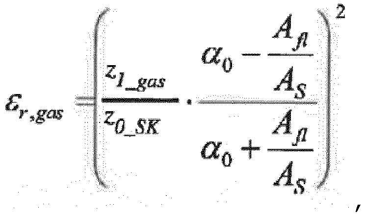
- Procédé (1) selon la revendication 1, caractérisé en ce que le signal de mesure transmis à travers le premier milieu résulte du signal d'émission avec prise en compte de l'atténuation due à la propagation le long de la ligne de signal (5) et/ou due à au moins une autre réflexion au niveau d'une autre interface.
- Procédé (1) selon la revendication 1 ou 2, caractérisé en ce que le rapport de la première impédance z 0 et de la deuxième impédance z1 est également pris en compte pour déterminer la permittivité relative εr du deuxième milieu.
- Procédé (1) selon l'une des revendications 1 à 3, caractérisé en ce que le deuxième milieu est le milieu de traitement (4, 4a, 4b) ou, dans le cas d'un milieu de processus (4, 4a, 4b) à plusieurs composants, le composant est le plus élevé du milieu de traitement (4, 4a, 4b), en ce que la réflexion du signal de mesure est effectuée sur la surface du milieu de traitement (4, 4a, 4b) ou du composant le plus élevé du milieu de traitement (4, 4a, 4b) et en ce que le signal de réflexion a une amplitude Alev.
- Procédé (1) selon la revendication 4, caractérisé en ce que l'amplitude du signal de réflexion Alev est corrigée de façon à prendre en compte l'atténuation du signal de mesure, due à la propagation dans le milieu gazeux (8) disposé au-dessus du milieu de traitement (4, 4a, 4b), pour déterminer la permittivité relative εr,pm_1 du milieu de traitement ou du composant le plus élevé du milieu de traitement (4, 4a, 4b).
- Procédé (1) selon la revendication 5, caractérisé en ce que différents coefficients d'atténuation α sont pris en compte lors de la détermination de l'amplitude corrigée Alev_cr en fonction du niveau X du milieu de traitement et donc du trajet du signal de mesure.
- Procédé (1) selon l'une des revendications 5 et 6, caractérisé en ce que l'amplitude corrigée Alev_cr est déterminée en fonction du niveau X du milieu de traitement selon l'une des formules (16) suivantes :-
 -
- -
-
- Procédé (1) selon l'une des revendications 4 à 7, caractérisé en ce que la détermination (17) de la permittivité relative εr,pm_1 du milieu de traitement (4, 4a, 4b) ou du composant le plus élevé du milieu de traitement (4, 4a, 4b) est effectuée selon la formule suivante :

- Procédé (1) selon l'une des revendications 1 à 8, caractérisé en ce que le milieu de traitement (4, 4a, 4b) comporte au moins trois composants, et en ce qu'au moins la permittivité relative εr,pm_n du composant n est déterminée pour déterminer la position d'une interface entre un composant n et un composant (n + 1), le composant n correspondant au premier milieu et le composant (n + 1) correspondant au deuxième milieu, la détermination étant effectuée selon la formule suivante :

l'amplitude corrigée prenant en compte l'atténuation du signal de mesure due à la propagation dans le milieu gazeux situé au-dessus du milieu de traitement et/ou dans le ou les composants du milieu de traitement qui sont disposés au-dessus du composant n,
et Ax_n étant l'amplitude du signal de mesure transmis à travers le premier milieu ou composant n et Ax_n étant déterminée selon la formule suivante :
- Procédé (1) selon l'une des revendications 1 à 9, caractérisé en ce que la vitesse de propagation du signal de mesure et du signal de réflexion dans le deuxième milieu est déterminée en fonction de la permittivité relative εr déterminée, en ce que le temps de propagation du signal de mesure et du signal de réflexion est déterminé et en ce que, à partir de là, au moins le niveau du milieu de traitement (4, 4a, 4b) et/ou la position d'une interface entre un premier et un deuxième composant (4a, 4b) d'un milieu de traitement (4, 4a, 4b) à plusieurs composants sont déterminés.
- Dispositif de mesure de niveau (2) destiné à déterminer le niveau d'un milieu de traitement (4, 4a, 4b) dans un récipient (3), ledit dispositif comprenant au moins une ligne de signal (5) destinée à conduire un signal électromagnétique, une tête de ligne de signal (6) et une unité électronique (7), l'unité électronique (7) étant conçue pour générer un signal d'émission en forme d'impulsion, le signal d'émission se propageant sous la forme d'un signal de mesure le long de la ligne de signal (5) et l'unité électronique (7) étant conçue pour détecter et évaluer au moins un signal de réflexion d'amplitude Arefl' le signal de réflexion correspondant à une réflexion du signal de mesure au niveau d'une interface entre un premier et un deuxième milieu, le premier milieu ayant une première impédance z 0 et le deuxième milieu ayant une deuxième impédance z1,
l'unité électronique (7) étant conçue pour déterminer la permittivité relative εr du deuxième milieu au moins en fonction de l'amplitude du signal de mesure transmis à travers le premier milieu et de l'amplitude Arefl du signal de réflexion,
caractérisé en ce que
la tête de ligne de signal (6) est reliée au récipient (3) par le biais d'un raccord de traitement (9) de préférence en forme de bride, le deuxième milieu est un milieu gazeux (8) qui est disposé au-dessus du milieu de traitement (4, 4a, 4b) et la réflexion du signal de mesure est effectuée au niveau de l'interface entre le raccord de traitement (9) de préférence en forme de bride et l'intérieur du récipient (3), et
la détermination (12) de la permittivité relative εr,gas du milieu gazeux (8) est effectuée selon la formule suivante :
- Dispositif de mesure de niveau (2) selon la revendication 11, caractérisé en ce que, en fonctionnement, le dispositif de mesure de niveau (2) met en œuvre un procédé (1) selon l'une des revendications 1 à 10.
Applications Claiming Priority (1)
| Application Number | Priority Date | Filing Date | Title |
|---|---|---|---|
| DE102017108702.8A DE102017108702A1 (de) | 2017-04-24 | 2017-04-24 | Verfahren zur Bestimmung des Füllstandes und Füllstandmessgerät |
Publications (2)
| Publication Number | Publication Date |
|---|---|
| EP3396334A1 EP3396334A1 (fr) | 2018-10-31 |
| EP3396334B1 true EP3396334B1 (fr) | 2021-05-26 |
Family
ID=61691853
Family Applications (1)
| Application Number | Title | Priority Date | Filing Date |
|---|---|---|---|
| EP18162742.3A Active EP3396334B1 (fr) | 2017-04-24 | 2018-03-20 | Procédé de détermination de niveau de remplissage et appareil de mesure de niveau de remplissage |
Country Status (4)
| Country | Link |
|---|---|
| US (1) | US10782175B2 (fr) |
| EP (1) | EP3396334B1 (fr) |
| CN (1) | CN108827423B (fr) |
| DE (1) | DE102017108702A1 (fr) |
Cited By (1)
| Publication number | Priority date | Publication date | Assignee | Title |
|---|---|---|---|---|
| WO2024223324A1 (fr) * | 2023-04-27 | 2024-10-31 | Vega Grieshaber Kg | Dispositif de mesure de niveau de remplissage pour automatisation de processus dans un environnement industriel ou privé |
Families Citing this family (3)
| Publication number | Priority date | Publication date | Assignee | Title |
|---|---|---|---|---|
| EP3492911B1 (fr) * | 2017-11-29 | 2025-04-16 | Heraeus Quarzglas GmbH & Co. KG | Procédé de détermination de la concentration d'un composant supplémentaire dans un corps en matériau céramique ou vitreux |
| JP2024157837A (ja) * | 2023-04-26 | 2024-11-08 | 株式会社キーエンス | レベル計 |
| DE102023131085A1 (de) * | 2023-11-09 | 2025-05-15 | Krohne S.A.S. | Verfahren zum Betreiben eines TDR-Füllstandmessgeräts und TDRFüllstandmessgerät |
Family Cites Families (13)
| Publication number | Priority date | Publication date | Assignee | Title |
|---|---|---|---|---|
| US5811677A (en) * | 1996-10-07 | 1998-09-22 | Bindicator Company | Material interface level sensing |
| US6782328B2 (en) | 1999-01-21 | 2004-08-24 | Rosemount Inc. | Measurement of concentration of material in a process fluid |
| US6477474B2 (en) | 1999-01-21 | 2002-11-05 | Rosemount Inc. | Measurement of process product dielectric constant using a low power radar level transmitter |
| US6701783B2 (en) | 2000-09-12 | 2004-03-09 | Vega Grieshaber Kg | Device and a process for determining the positions of border areas between different mediums |
| DE10044888A1 (de) * | 2000-09-12 | 2002-04-04 | Grieshaber Vega Kg | Vorrichtung und Verfahren zur Ermittlung der Positionen der Grenzflächen unterschiedlicher Medien |
| US7924216B2 (en) * | 2008-04-30 | 2011-04-12 | Rosemount Tank Radar Ab | Method of determining a disturbance echo profile for a radar level gauge system |
| DE102009002785A1 (de) | 2009-05-04 | 2010-11-11 | Endress + Hauser Gmbh + Co. Kg | Verfahren zur Füllstandsmessung |
| EP2365302B1 (fr) * | 2010-02-25 | 2012-05-23 | Sick Ag | Mesure de la distance par rapport à, au moins, une première surface limite |
| DE102012101725A1 (de) | 2012-03-01 | 2013-09-05 | Sick Ag | Verfahren zur Füllstandsmessung |
| DE102012105281A1 (de) | 2012-06-18 | 2013-12-19 | Endress + Hauser Gmbh + Co. Kg | Füllstandsmessgerät und Vorrichtung zur Bestimmung der Dielektrizitätszahl |
| US8823397B2 (en) * | 2012-09-27 | 2014-09-02 | Rosemount Tank Radar Ab | Interface detection |
| US8963769B2 (en) * | 2012-10-16 | 2015-02-24 | Magnetrol International, Incorporated | Guided wave radar interface measurement medium identification |
| DK2759813T3 (da) * | 2013-01-25 | 2016-06-06 | Sick Ag | Method and sensor for measuring the fill level of layered media |
-
2017
- 2017-04-24 DE DE102017108702.8A patent/DE102017108702A1/de not_active Withdrawn
-
2018
- 2018-03-20 EP EP18162742.3A patent/EP3396334B1/fr active Active
- 2018-04-12 US US15/951,342 patent/US10782175B2/en active Active
- 2018-04-24 CN CN201810373002.3A patent/CN108827423B/zh active Active
Non-Patent Citations (1)
| Title |
|---|
| None * |
Cited By (1)
| Publication number | Priority date | Publication date | Assignee | Title |
|---|---|---|---|---|
| WO2024223324A1 (fr) * | 2023-04-27 | 2024-10-31 | Vega Grieshaber Kg | Dispositif de mesure de niveau de remplissage pour automatisation de processus dans un environnement industriel ou privé |
Also Published As
| Publication number | Publication date |
|---|---|
| EP3396334A1 (fr) | 2018-10-31 |
| DE102017108702A1 (de) | 2018-10-25 |
| CN108827423B (zh) | 2021-10-08 |
| CN108827423A (zh) | 2018-11-16 |
| US20180306632A1 (en) | 2018-10-25 |
| US10782175B2 (en) | 2020-09-22 |
Similar Documents
| Publication | Publication Date | Title |
|---|---|---|
| EP3396334B1 (fr) | Procédé de détermination de niveau de remplissage et appareil de mesure de niveau de remplissage | |
| DE3009835C2 (fr) | ||
| DE102006017676B3 (de) | Verfahren zum Betrieb eines Coriolis-Massendurchflußmeßgeräts | |
| WO2006048395A1 (fr) | Dispositif de determination et/ou de controle du debit volumique et/ou massique d'un fluide | |
| EP2365302B1 (fr) | Mesure de la distance par rapport à, au moins, une première surface limite | |
| DE102007060579A1 (de) | Verfahren zur Ermittlung und/oder zur Beurteilung des Befüllzustands eines mit zumindest einem Medium gefüllten Behälter | |
| EP2527801A1 (fr) | Dispositif et procédé de détermination de caractéristiques de milieux et de récipients | |
| EP3447456B1 (fr) | Appareil de mesure de niveau de remplissage tdr et procédé de fonctionnement d'un appareil de mesure de niveau de remplissage tdr | |
| EP2527802A1 (fr) | Dispositif et procédé de détermination de caractéristiques de milieux et de récipients | |
| EP2652465B1 (fr) | Détermination de propriétés de fluide lors de la mesure d'un niveau de remplissage | |
| EP3388794B2 (fr) | Dispositif de mesure du débit destiné à mesurer le débit d'un fluide | |
| EP2847555B1 (fr) | Procédé de surveillance de l'état de fonctionnement d'un transducteur d'ultrasons dans un appareil de mesure de débit à ultrasons | |
| DE10051151A1 (de) | Verbesserungen auf dem Gebiet der Zeit-Bezirk-Reflexmessung | |
| DE102008055032A1 (de) | Anordnung und Verfahren zur Mehrphasendurchflussmessung | |
| DE10136754A1 (de) | Verfahren und Vorrichtung zur Dichtebestimmung | |
| EP2182380B1 (fr) | Procédé de détection de la superposition de pointe dans un spectre discret d'un signal de repérage | |
| AT520557B1 (de) | Verfahren zur Ermittlung eines korrigierten Werts für die viskositätsabhängige Schallgeschwindigkeit in einem zu untersuchenden Fluid | |
| EP0791838A1 (fr) | Procédé de mesure de la vitesse d'un cible-radar | |
| EP2739946B1 (fr) | Relation lineaire entre pistes | |
| EP2310811A2 (fr) | Procédé et dispositif de détermination d'un débit de fluide | |
| EP3244176B1 (fr) | Procédé de surveillance d'une jauge de niveau fonctionnant sur le principe du radar et jauge de niveau | |
| EP4030622A1 (fr) | Unité inductive de détection de proximité et procédé de détection des dysfonctionnements de l'unité inductive de détection de proximité | |
| DE102023131085A1 (de) | Verfahren zum Betreiben eines TDR-Füllstandmessgeräts und TDRFüllstandmessgerät | |
| DE10105652A1 (de) | Verfahren und Vorrichtung zur Grobunterscheidung eines Füllgutes in einem Behälter in Flüssigkeit oder Schüttgut | |
| EP4428500B1 (fr) | Procédé de fonctionnement d'un débitmètre à induction magnétique et débitmètre à induction magnétique |
Legal Events
| Date | Code | Title | Description |
|---|---|---|---|
| PUAI | Public reference made under article 153(3) epc to a published international application that has entered the european phase |
Free format text: ORIGINAL CODE: 0009012 |
|
| STAA | Information on the status of an ep patent application or granted ep patent |
Free format text: STATUS: THE APPLICATION HAS BEEN PUBLISHED |
|
| AK | Designated contracting states |
Kind code of ref document: A1 Designated state(s): AL AT BE BG CH CY CZ DE DK EE ES FI FR GB GR HR HU IE IS IT LI LT LU LV MC MK MT NL NO PL PT RO RS SE SI SK SM TR |
|
| AX | Request for extension of the european patent |
Extension state: BA ME |
|
| STAA | Information on the status of an ep patent application or granted ep patent |
Free format text: STATUS: REQUEST FOR EXAMINATION WAS MADE |
|
| 17P | Request for examination filed |
Effective date: 20190411 |
|
| RBV | Designated contracting states (corrected) |
Designated state(s): AL AT BE BG CH CY CZ DE DK EE ES FI FR GB GR HR HU IE IS IT LI LT LU LV MC MK MT NL NO PL PT RO RS SE SI SK SM TR |
|
| RIC1 | Information provided on ipc code assigned before grant |
Ipc: G01F 23/284 20060101AFI20201125BHEP Ipc: G01S 13/10 20060101ALI20201125BHEP Ipc: G01F 23/00 20060101ALI20201125BHEP Ipc: G01S 7/41 20060101ALI20201125BHEP Ipc: G01S 13/88 20060101ALI20201125BHEP |
|
| GRAP | Despatch of communication of intention to grant a patent |
Free format text: ORIGINAL CODE: EPIDOSNIGR1 |
|
| STAA | Information on the status of an ep patent application or granted ep patent |
Free format text: STATUS: GRANT OF PATENT IS INTENDED |
|
| GRAS | Grant fee paid |
Free format text: ORIGINAL CODE: EPIDOSNIGR3 |
|
| INTG | Intention to grant announced |
Effective date: 20210104 |
|
| INTG | Intention to grant announced |
Effective date: 20210113 |
|
| GRAA | (expected) grant |
Free format text: ORIGINAL CODE: 0009210 |
|
| STAA | Information on the status of an ep patent application or granted ep patent |
Free format text: STATUS: THE PATENT HAS BEEN GRANTED |
|
| AK | Designated contracting states |
Kind code of ref document: B1 Designated state(s): AL AT BE BG CH CY CZ DE DK EE ES FI FR GB GR HR HU IE IS IT LI LT LU LV MC MK MT NL NO PL PT RO RS SE SI SK SM TR |
|
| REG | Reference to a national code |
Ref country code: GB Ref legal event code: FG4D Free format text: NOT ENGLISH |
|
| REG | Reference to a national code |
Ref country code: CH Ref legal event code: EP |
|
| REG | Reference to a national code |
Ref country code: DE Ref legal event code: R096 Ref document number: 502018005381 Country of ref document: DE |
|
| REG | Reference to a national code |
Ref country code: AT Ref legal event code: REF Ref document number: 1396689 Country of ref document: AT Kind code of ref document: T Effective date: 20210615 |
|
| REG | Reference to a national code |
Ref country code: IE Ref legal event code: FG4D Free format text: LANGUAGE OF EP DOCUMENT: GERMAN |
|
| REG | Reference to a national code |
Ref country code: LT Ref legal event code: MG9D |
|
| PG25 | Lapsed in a contracting state [announced via postgrant information from national office to epo] |
Ref country code: HR Free format text: LAPSE BECAUSE OF FAILURE TO SUBMIT A TRANSLATION OF THE DESCRIPTION OR TO PAY THE FEE WITHIN THE PRESCRIBED TIME-LIMIT Effective date: 20210526 Ref country code: BG Free format text: LAPSE BECAUSE OF FAILURE TO SUBMIT A TRANSLATION OF THE DESCRIPTION OR TO PAY THE FEE WITHIN THE PRESCRIBED TIME-LIMIT Effective date: 20210826 Ref country code: LT Free format text: LAPSE BECAUSE OF FAILURE TO SUBMIT A TRANSLATION OF THE DESCRIPTION OR TO PAY THE FEE WITHIN THE PRESCRIBED TIME-LIMIT Effective date: 20210526 Ref country code: FI Free format text: LAPSE BECAUSE OF FAILURE TO SUBMIT A TRANSLATION OF THE DESCRIPTION OR TO PAY THE FEE WITHIN THE PRESCRIBED TIME-LIMIT Effective date: 20210526 |
|
| REG | Reference to a national code |
Ref country code: NL Ref legal event code: MP Effective date: 20210526 |
|
| PG25 | Lapsed in a contracting state [announced via postgrant information from national office to epo] |
Ref country code: RS Free format text: LAPSE BECAUSE OF FAILURE TO SUBMIT A TRANSLATION OF THE DESCRIPTION OR TO PAY THE FEE WITHIN THE PRESCRIBED TIME-LIMIT Effective date: 20210526 Ref country code: SE Free format text: LAPSE BECAUSE OF FAILURE TO SUBMIT A TRANSLATION OF THE DESCRIPTION OR TO PAY THE FEE WITHIN THE PRESCRIBED TIME-LIMIT Effective date: 20210526 Ref country code: NO Free format text: LAPSE BECAUSE OF FAILURE TO SUBMIT A TRANSLATION OF THE DESCRIPTION OR TO PAY THE FEE WITHIN THE PRESCRIBED TIME-LIMIT Effective date: 20210826 Ref country code: LV Free format text: LAPSE BECAUSE OF FAILURE TO SUBMIT A TRANSLATION OF THE DESCRIPTION OR TO PAY THE FEE WITHIN THE PRESCRIBED TIME-LIMIT Effective date: 20210526 Ref country code: PT Free format text: LAPSE BECAUSE OF FAILURE TO SUBMIT A TRANSLATION OF THE DESCRIPTION OR TO PAY THE FEE WITHIN THE PRESCRIBED TIME-LIMIT Effective date: 20210927 Ref country code: PL Free format text: LAPSE BECAUSE OF FAILURE TO SUBMIT A TRANSLATION OF THE DESCRIPTION OR TO PAY THE FEE WITHIN THE PRESCRIBED TIME-LIMIT Effective date: 20210526 Ref country code: IS Free format text: LAPSE BECAUSE OF FAILURE TO SUBMIT A TRANSLATION OF THE DESCRIPTION OR TO PAY THE FEE WITHIN THE PRESCRIBED TIME-LIMIT Effective date: 20210926 Ref country code: GR Free format text: LAPSE BECAUSE OF FAILURE TO SUBMIT A TRANSLATION OF THE DESCRIPTION OR TO PAY THE FEE WITHIN THE PRESCRIBED TIME-LIMIT Effective date: 20210827 |
|
| PG25 | Lapsed in a contracting state [announced via postgrant information from national office to epo] |
Ref country code: NL Free format text: LAPSE BECAUSE OF FAILURE TO SUBMIT A TRANSLATION OF THE DESCRIPTION OR TO PAY THE FEE WITHIN THE PRESCRIBED TIME-LIMIT Effective date: 20210526 |
|
| PG25 | Lapsed in a contracting state [announced via postgrant information from national office to epo] |
Ref country code: RO Free format text: LAPSE BECAUSE OF FAILURE TO SUBMIT A TRANSLATION OF THE DESCRIPTION OR TO PAY THE FEE WITHIN THE PRESCRIBED TIME-LIMIT Effective date: 20210526 Ref country code: DK Free format text: LAPSE BECAUSE OF FAILURE TO SUBMIT A TRANSLATION OF THE DESCRIPTION OR TO PAY THE FEE WITHIN THE PRESCRIBED TIME-LIMIT Effective date: 20210526 Ref country code: CZ Free format text: LAPSE BECAUSE OF FAILURE TO SUBMIT A TRANSLATION OF THE DESCRIPTION OR TO PAY THE FEE WITHIN THE PRESCRIBED TIME-LIMIT Effective date: 20210526 Ref country code: SM Free format text: LAPSE BECAUSE OF FAILURE TO SUBMIT A TRANSLATION OF THE DESCRIPTION OR TO PAY THE FEE WITHIN THE PRESCRIBED TIME-LIMIT Effective date: 20210526 Ref country code: SK Free format text: LAPSE BECAUSE OF FAILURE TO SUBMIT A TRANSLATION OF THE DESCRIPTION OR TO PAY THE FEE WITHIN THE PRESCRIBED TIME-LIMIT Effective date: 20210526 Ref country code: EE Free format text: LAPSE BECAUSE OF FAILURE TO SUBMIT A TRANSLATION OF THE DESCRIPTION OR TO PAY THE FEE WITHIN THE PRESCRIBED TIME-LIMIT Effective date: 20210526 Ref country code: ES Free format text: LAPSE BECAUSE OF FAILURE TO SUBMIT A TRANSLATION OF THE DESCRIPTION OR TO PAY THE FEE WITHIN THE PRESCRIBED TIME-LIMIT Effective date: 20210526 |
|
| REG | Reference to a national code |
Ref country code: DE Ref legal event code: R097 Ref document number: 502018005381 Country of ref document: DE |
|
| PLBE | No opposition filed within time limit |
Free format text: ORIGINAL CODE: 0009261 |
|
| STAA | Information on the status of an ep patent application or granted ep patent |
Free format text: STATUS: NO OPPOSITION FILED WITHIN TIME LIMIT |
|
| 26N | No opposition filed |
Effective date: 20220301 |
|
| PG25 | Lapsed in a contracting state [announced via postgrant information from national office to epo] |
Ref country code: IS Free format text: LAPSE BECAUSE OF FAILURE TO SUBMIT A TRANSLATION OF THE DESCRIPTION OR TO PAY THE FEE WITHIN THE PRESCRIBED TIME-LIMIT Effective date: 20210926 Ref country code: AL Free format text: LAPSE BECAUSE OF FAILURE TO SUBMIT A TRANSLATION OF THE DESCRIPTION OR TO PAY THE FEE WITHIN THE PRESCRIBED TIME-LIMIT Effective date: 20210526 |
|
| PG25 | Lapsed in a contracting state [announced via postgrant information from national office to epo] |
Ref country code: IT Free format text: LAPSE BECAUSE OF FAILURE TO SUBMIT A TRANSLATION OF THE DESCRIPTION OR TO PAY THE FEE WITHIN THE PRESCRIBED TIME-LIMIT Effective date: 20210526 |
|
| PG25 | Lapsed in a contracting state [announced via postgrant information from national office to epo] |
Ref country code: MC Free format text: LAPSE BECAUSE OF FAILURE TO SUBMIT A TRANSLATION OF THE DESCRIPTION OR TO PAY THE FEE WITHIN THE PRESCRIBED TIME-LIMIT Effective date: 20210526 |
|
| REG | Reference to a national code |
Ref country code: BE Ref legal event code: MM Effective date: 20220331 |
|
| PG25 | Lapsed in a contracting state [announced via postgrant information from national office to epo] |
Ref country code: LU Free format text: LAPSE BECAUSE OF NON-PAYMENT OF DUE FEES Effective date: 20220320 Ref country code: IE Free format text: LAPSE BECAUSE OF NON-PAYMENT OF DUE FEES Effective date: 20220320 |
|
| PG25 | Lapsed in a contracting state [announced via postgrant information from national office to epo] |
Ref country code: BE Free format text: LAPSE BECAUSE OF NON-PAYMENT OF DUE FEES Effective date: 20220331 |
|
| P01 | Opt-out of the competence of the unified patent court (upc) registered |
Effective date: 20230607 |
|
| PGFP | Annual fee paid to national office [announced via postgrant information from national office to epo] |
Ref country code: GB Payment date: 20230428 Year of fee payment: 6 |
|
| PG25 | Lapsed in a contracting state [announced via postgrant information from national office to epo] |
Ref country code: HU Free format text: LAPSE BECAUSE OF FAILURE TO SUBMIT A TRANSLATION OF THE DESCRIPTION OR TO PAY THE FEE WITHIN THE PRESCRIBED TIME-LIMIT; INVALID AB INITIO Effective date: 20180320 |
|
| PG25 | Lapsed in a contracting state [announced via postgrant information from national office to epo] |
Ref country code: MK Free format text: LAPSE BECAUSE OF FAILURE TO SUBMIT A TRANSLATION OF THE DESCRIPTION OR TO PAY THE FEE WITHIN THE PRESCRIBED TIME-LIMIT Effective date: 20210526 Ref country code: CY Free format text: LAPSE BECAUSE OF FAILURE TO SUBMIT A TRANSLATION OF THE DESCRIPTION OR TO PAY THE FEE WITHIN THE PRESCRIBED TIME-LIMIT Effective date: 20210526 |
|
| REG | Reference to a national code |
Ref country code: AT Ref legal event code: MM01 Ref document number: 1396689 Country of ref document: AT Kind code of ref document: T Effective date: 20230320 |
|
| PG25 | Lapsed in a contracting state [announced via postgrant information from national office to epo] |
Ref country code: TR Free format text: LAPSE BECAUSE OF FAILURE TO SUBMIT A TRANSLATION OF THE DESCRIPTION OR TO PAY THE FEE WITHIN THE PRESCRIBED TIME-LIMIT Effective date: 20210526 |
|
| PG25 | Lapsed in a contracting state [announced via postgrant information from national office to epo] |
Ref country code: AT Free format text: LAPSE BECAUSE OF NON-PAYMENT OF DUE FEES Effective date: 20230320 |
|
| PG25 | Lapsed in a contracting state [announced via postgrant information from national office to epo] |
Ref country code: AT Free format text: LAPSE BECAUSE OF NON-PAYMENT OF DUE FEES Effective date: 20230320 |
|
| PG25 | Lapsed in a contracting state [announced via postgrant information from national office to epo] |
Ref country code: MT Free format text: LAPSE BECAUSE OF FAILURE TO SUBMIT A TRANSLATION OF THE DESCRIPTION OR TO PAY THE FEE WITHIN THE PRESCRIBED TIME-LIMIT Effective date: 20210526 |
|
| GBPC | Gb: european patent ceased through non-payment of renewal fee |
Effective date: 20240320 |
|
| PG25 | Lapsed in a contracting state [announced via postgrant information from national office to epo] |
Ref country code: GB Free format text: LAPSE BECAUSE OF NON-PAYMENT OF DUE FEES Effective date: 20240320 |
|
| PG25 | Lapsed in a contracting state [announced via postgrant information from national office to epo] |
Ref country code: GB Free format text: LAPSE BECAUSE OF NON-PAYMENT OF DUE FEES Effective date: 20240320 |
|
| PGFP | Annual fee paid to national office [announced via postgrant information from national office to epo] |
Ref country code: DE Payment date: 20250515 Year of fee payment: 8 |
|
| PGFP | Annual fee paid to national office [announced via postgrant information from national office to epo] |
Ref country code: CH Payment date: 20250401 Year of fee payment: 8 |
|
| REG | Reference to a national code |
Ref country code: CH Ref legal event code: U11 Free format text: ST27 STATUS EVENT CODE: U-0-0-U10-U11 (AS PROVIDED BY THE NATIONAL OFFICE) Effective date: 20260401 |
|
| PGFP | Annual fee paid to national office [announced via postgrant information from national office to epo] |
Ref country code: AT Payment date: 20260410 Year of fee payment: 5 |
|
| PGFP | Annual fee paid to national office [announced via postgrant information from national office to epo] |
Ref country code: FR Payment date: 20260320 Year of fee payment: 9 |