EP3401471A1 - Schliessmechanismus für verriegelungsbeschlag mindestens eine schlossnuss umfassend - Google Patents
Schliessmechanismus für verriegelungsbeschlag mindestens eine schlossnuss umfassend Download PDFInfo
- Publication number
- EP3401471A1 EP3401471A1 EP18171659.8A EP18171659A EP3401471A1 EP 3401471 A1 EP3401471 A1 EP 3401471A1 EP 18171659 A EP18171659 A EP 18171659A EP 3401471 A1 EP3401471 A1 EP 3401471A1
- Authority
- EP
- European Patent Office
- Prior art keywords
- follower
- locking mechanism
- locking
- abutment
- positions
- Prior art date
- Legal status (The legal status is an assumption and is not a legal conclusion. Google has not performed a legal analysis and makes no representation as to the accuracy of the status listed.)
- Granted
Links
Images

Classifications
-
- E—FIXED CONSTRUCTIONS
- E05—LOCKS; KEYS; WINDOW OR DOOR FITTINGS; SAFES
- E05B—LOCKS; ACCESSORIES THEREFOR; HANDCUFFS
- E05B63/00—Locks or fastenings with special structural characteristics
- E05B63/0065—Operating modes; Transformable to different operating modes
-
- E—FIXED CONSTRUCTIONS
- E05—LOCKS; KEYS; WINDOW OR DOOR FITTINGS; SAFES
- E05B—LOCKS; ACCESSORIES THEREFOR; HANDCUFFS
- E05B15/00—Other details of locks; Parts for engagement by bolts of fastening devices
- E05B15/0013—Followers; Bearings therefor
-
- E—FIXED CONSTRUCTIONS
- E05—LOCKS; KEYS; WINDOW OR DOOR FITTINGS; SAFES
- E05C—BOLTS OR FASTENING DEVICES FOR WINGS, SPECIALLY FOR DOORS OR WINDOWS
- E05C9/00—Arrangements of simultaneously actuated bolts or other securing devices at well-separated positions on the same wing
- E05C9/06—Arrangements of simultaneously actuated bolts or other securing devices at well-separated positions on the same wing with three or more sliding bars
- E05C9/063—Arrangements of simultaneously actuated bolts or other securing devices at well-separated positions on the same wing with three or more sliding bars extending along three or more sides of the wing or frame
- E05C9/066—Locks for windows or doors specially adapted for tilt and turn
Definitions
- the invention relates to a locking mechanism for a carpentry locking fitting, said locking mechanism comprising at least one follower rotatably mounted in a housing and cooperating with at least one locking member and / or a transmission member, such as an easel, an operating rod, a drive pinion, to push this locking member and / or transmission between a position, including locking, and at least one unlocking position, by rotation of said follower according to a given race between two extreme positions angularly offset.
- a locking mechanism for a carpentry locking fitting said locking mechanism comprising at least one follower rotatably mounted in a housing and cooperating with at least one locking member and / or a transmission member, such as an easel, an operating rod, a drive pinion, to push this locking member and / or transmission between a position, including locking, and at least one unlocking position, by rotation of said follower according to a given race between two extreme positions angularly offset.
- the present invention relates to the field of carpentry fittings and more particularly lock fittings for doors, windows or the like, incorporating at least one operable nut, in particular, via a handle.
- the door locks or casement window having a housing very often recessed in rabbet of the amount before the opening of this door or window.
- This housing houses a locking mechanism comprising, essentially, a follower rotatably mounted in this housing about an axis perpendicular to the plane of the opening. On this follower can act a user through a handle most often intervening on a square maneuvering through a section opening adjusted in the axis of the follower.
- a locking member usually a latch bolt, so that, by rotation of the follower in a given angular stroke and under the impetus of the handle accessible to the user, it is obtained, starting from a locking position of the latch bolt, its recoil in an unlocked position.
- the amplitude of rotation imparted to the follower by the handle in the context of such a lock to move from this locking position of the latch bolt in its unlocked position is at most 45 °.
- the follower acts directly or indirectly on an operating rod, to simultaneously provide locking control, as the case of unlocking, of several locking members , such as rollers, hook bolts or the like, each adapted to cooperate with a strike, to further secure a door or window opening against a frame.
- the rotation printed to the follower to move from a locked position to an unlocked position is about 90 °.
- This rotation usually consists in pushing a handle from a vertical locking position downwards to a horizontal unlocking position.
- a locking mechanism type espagnolette or espagnolette-lock offers several possibilities of opening a door or window opening it comes equipped.
- a door leaf or window can be brought into a ventilating opening position, said by knocking down.
- This second open position is frequently obtained through a complementary rotation of the follower, therefore the handle acting on the latter.
- the handle acting on the latter.
- it is usual, starting from the unlocking position in which the handle is horizontal, to raise it vertically, by rotating 90 ° complementary, to reach this second unlocking position.
- This represents a total rotation of 180 ° of this handle, starting from its initial locking position in which it extends vertically downwards.
- the direction of the angular displacement and the amplitude of this displacement conferred on the follower depends on the type of fitting locking, but also the mobility of the sliding leaf relative to the frame.
- the unlocking and opening control results from the rotation of a handle, from a raised vertical position, in a horizontal position at 90 ° and consequently a rotation of similar amplitude of the follower on which this handle acts.
- this amplitude of rotation printed on the follower is 90 ° or 180 ° depending on whether it is desired to bring a translatory sliding leaf into a ventilation or opening position.
- a first rotation of the handle from a vertical position raised in a horizontal position leads to the opening of such a sliding switchable translationally in a ventilation position by flipping, while a rotation complementary to this handle downwards generates the shift of this translating sliding leaf in a plane parallel to the frame to allow its sliding opening.
- This amplitude of rotation printed by the handle on the nut of a locking mechanism of a fitting coming to equip a sliding-sliding door is still different compared to the previously described solutions for, for example, during the unlocking command of a such sliding-sliding opening, ensure, first unlocking, then lifting the opening which allows its sliding.
- a lock fitting locking mechanism comprising a follower must incorporate stop means limiting at a given amplitude the angular travel of this follower between two determined extreme positions, this depending on the application of this mechanism locking to a specific type of carpentry.
- This locking mechanism comprises at least one follower rotatably mounted in a housing and cooperating with at least one transmission member to push this transmission member between a position and at least one unlocking position, by rotation of said follower according to a given stroke between two extreme positions angularly offset.
- This locking mechanism also comprises stop means capable of occupying, on the one hand, a first position in which they cooperate with the follower to allow rotation of the latter in a first angular stroke and, on the other hand, at least a second position in which these stop means allow the rotation of said follower in a second angular stroke distinguished from the first angular stroke by its amplitude, these stop means comprising a first stop member, on the one hand, mounted in the housing movably between said first position and the second position and, on the other hand, cooperating with complementary abutment members, which is provided with the follower.
- This locking mechanism comprises, also and in combination, means for selecting the position of said stop means.
- the solution according to the invention consists in proposing a locking mechanism providing the possibility to adjust, on demand, this angular stroke of the follower so as to have a locking mechanism that is multiple applications.
- the invention relates to a locking mechanism for carpentry locking fitting.
- This locking mechanism comprises at least one follower rotatably mounted in a housing and cooperating with at least one locking member and / or a transmission member, such as a bridge, an operating rod, a drive pinion, to push this locking member and / or this transmission member between a position, including locking, and at least one unlocking position, by rotation of said follower according to a given stroke between two extreme positions angularly offset.
- a transmission member such as a bridge, an operating rod, a drive pinion
- This locking mechanism also comprises stop means capable of occupying, on the one hand, a first position in which they cooperate with the follower to allow rotation of the latter in a first angular stroke and, on the other hand, at least a second position in which these stop means allow the rotation of said follower in a second angular stroke differing from the first angular stroke, as the case may be, by its amplitude and / or by at least one of the extreme positions, these means of stop comprising a first stop member, on the one hand, mounted in the housing movably between said first position and the second position and, on the other hand, cooperating with complementary abutment members, which is provided with the follower.
- This locking mechanism comprises, also and in combination, means for selecting the position of said stop means.
- This locking mechanism is characterized in that the complementary abutment members are in the form of axially offset ring sectors at the periphery of a hub of the follower and that the first abutment member is movably mounted in the housing, between at least the first position and the second position, and in a coaxial direction to the follower.
- the advantages deriving from the present invention essentially consist in a standardization of locking mechanisms for door or window-type joinery, making it possible to rationalize the manufacture of locking fittings incorporating such a mechanism, this according to the different applications. This rationalization results in improved parts inventory management, lower production costs and greater responsiveness to market demand.
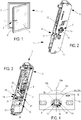
- the present invention relates to a locking mechanism 1, an exemplary embodiment of which is illustrated in FIGS. Figures 2 to 4 , this locking mechanism 1 being applicable to locking fittings 2 fitted to a building joinery, such as a door, window or the like 3.
- the locking fitting 2 can be in the form of a simple lock or a cremone equipping the front post 6 of the leaf 4 and acting on one or more locking members provided for cooperating, in particular, with strikes arranged in correspondence on the sleeping frame 5.
- this locking mechanism 1 of the locking fitting 2 through a handle 7.
- This is illustrated in a horizontal position on the figure 1 corresponding, here, to the position of unlocking and French opening of the leaf 4.
- the handle 7 is usually rotated 90 ° so as to extend vertically downwards.
- door or window leaves can be opened only by rotation around a vertical pivot axis, others are also able to open by flipping into a ventilation position.
- Such an opening consists of a pivoting of a leaf around an axis of horizontal rotation, often materialized by the inner cross member of this leaf.
- the locking mechanism 1 of such a locking fitting 2 comprises a follower 8 rotatably mounted in a housing 9, about an axis of rotation 10 substantially perpendicular to the plane of the housing 9, or substantially perpendicular to the plane of the housing.
- leaf 4 comprising such a locking mechanism 1.
- the follower 8 comprises, generally, a hub 11 kept rotated on both sides by the side walls 12, 13 of this housing 9.
- the handle 7 rotates the follower 8 more often via a maneuvering square 14 (reference 4 on figure 4 ?) engaging in an aperture 15 of adapted section in the hub 11.
- This follower 8 cooperates, as appropriate, directly with a locking member, such as a latch bolt, a dead bolt or the like, and / or, as in the embodiment corresponding to the Figures 2 to 4 , with at least one transmission member 16 which can take the form of a bridge 17, able to act on an operating rod or the like, either directly that of such a rod, or even a pinion drive.
- a locking member such as a latch bolt, a dead bolt or the like
- at least one transmission member 16 which can take the form of a bridge 17, able to act on an operating rod or the like, either directly that of such a rod, or even a pinion drive.
- a follower 8 of a locking mechanism 1 is also able to act simultaneously on two trestles or two separate operating rods, one of which is even to transmit a movement to locking members located above the housing 9 and the other to other locking members disposed under this housing 9.
- the follower 8 is capable of being rotated in a given angular stroke 18a, 18b, this between two positions. extremes 19a, 20a; 19b, 20b, angularly distinct and / or staggered.
- the locking mechanism 1 comprises stop means 21, cooperating with the follower 8, and able to occupy a first position 22 in which they allow the follower 8 to rotate in a first angular stroke 18a these abutment means 21 can still occupy at least a second position 23 in which they allow the follower 8 to pivot about its axis 10 in a second angular stroke 18b.
- This is distinguished from the first angular stroke 18a, as the case may be, by its amplitude and / or by at least one of the extreme positions 19a, 19b; 20a, 20b.
- this locking mechanism 1 comprises means 24 for selecting the position 22 or 23 of these abutment means 21.
- abutment means 21 advantageously comprise a first abutment member 25 mounted in the housing 9 so as to movable between said first position 22 and the second position 23.
- This first abutment member 25 is also mounted in this housing 9 in a manner adapted to cooperate with complementary abutment members 26a, 26b, which is provided with the follower 8, more particularly at the periphery of the hub 11.
- this first stop member 25 is made to cooperate, on the one hand, with the complementary abutment members 26a, when in its first position 22, and on the other hand with the complementary abutment members 26b. when in his second position 23.
- the present invention is not limited to only two possible positions 22, 23 of the stop means 21 and the complementary abutment members are a function of these different positions 22, 23 possible.
- first stop member 25 may be in the form of at least one locking pin 27a, 27b
- complementary abutment members 26a, 26b can borrow they themselves, any configuration, especially at the periphery of the hub 11. Their disposition is determined, on the one hand, to allow rotation of the follower 8 in an angular stroke 18a or 18b, and, secondly, to define the positions angular extremes, as appropriate, 19a, 20a or 19b, 20b
- these complementary abutment members 26a, 26b are in the form of ring sectors 28a, 28b at the periphery of the hub 11.
- the locking finger or fingers 27a, 27b, defining the first stop member 25 at least one of these locking fingers 27a, 27b is made to cooperate with at least one of the crown 28a, 28b.
- these ring sectors 28a, 28b are advantageously axially offset at the periphery of the hub 11 of the follower 8, while the first stop member 25 is itself mounted in the housing 9 between at least the first position 22 and the second position 23 in a coaxial direction to the follower 8.
- the locking finger or fingers 27a, 27b (corresponding to the first abutment member 25) cooperate more particularly with the off-hooks 29 (defined by the ring sectors 28a, 28b at the periphery of the hub 11, which are unhooked and which, in turn, determine the extreme angular positions 19a, 20a or, as the case may be, 19b, 20b), the amplitude of the angular races 18a, 18b, depends inversely on the size of these sectors of rings 28a, 28b and the section of said locking fingers 27a , 27b.
- the selection means 24 of the positions 22, 23 of the abutment means 21 comprise indexing means 30 of these abutment means 21 in these positions 22, 23.
- these indexing means 30 take the form of retractable elastic retaining means 31 capable of cooperating with complementary retaining means 32 adapted as a function of the positions 22, 23 to be indexed.
- the resilient retaining means 31 are defined in the form of an elastic blade and equip the housing 9, while the complementary retaining means 32 are associated with the first abutment member 25.
- the elastic blade is preferably implanted in the front portion 33 of the housing 9, accessible portion, usually in carpentry rabbet.
- This elastic blade comprises, on the one hand, an end 34 secured to the housing 9 (more particularly to one of the walls 12 of the housing 9) and, on the other hand, a handling end 35. Between these ends 34, 35, this elastic blade defines a bend 36 adapted to engage in one 37a or the other 37b of the grooves corresponding to the complementary retaining means 32 that includes the first stop member 25.
- the handling end 35 is accessible to the user through the side wall 13 of the housing 9, opposite that 12 which is secured to the elastic blade. This means that only a warned operator and at the time of mounting the locking fitting 2 on a joinery 3, can intervene on these selection means 24, thereby avoiding possible mishandling by the user.
- guide means 38 (adapted in the housing 9) contribute to guiding the first stop member 25 in its movements between its first 22 and second 23 positions.
- this first abutment member 25 (defining at least one locking pin 25a, 25b) is mounted to move in translation on a screw guide 39 that includes the housing 9 and passing through the latter for the passage of a fixing screw of a handle 7.
- the locking mechanism 1 offers the possibility of selecting between different angular races 18a, 18b of the follower 8, it may still be advantageous to be able to choose between different angular orientations of the handle 7 that this locking mechanism 1 is intended to receive.
- the opening 15 in the follower 8 is defined able to receive this square 14 in two positions 40 41 angularly offset from each other by 45 °.
- a handle 7 can be mounted on the locking mechanism 1 in different angular positions offset by 45 ° and this, over 360 °.
- the advantages resulting from the present invention consist in an application of the locking mechanism according to the invention to multiple lock fittings for joinery type lock, espagnolette or other. This leads to a standardization of the manufacture of these locking mechanisms and storage optimization of the parts that compose them.
Landscapes
- Engineering & Computer Science (AREA)
- Structural Engineering (AREA)
- Mechanical Engineering (AREA)
- Lock And Its Accessories (AREA)
Applications Claiming Priority (1)
| Application Number | Priority Date | Filing Date | Title |
|---|---|---|---|
| FR1754143A FR3066213B1 (fr) | 2017-05-11 | 2017-05-11 | Mecanisme pour ferrure de verrouillage comprenant au moins un fouillot |
Publications (2)
| Publication Number | Publication Date |
|---|---|
| EP3401471A1 true EP3401471A1 (de) | 2018-11-14 |
| EP3401471B1 EP3401471B1 (de) | 2019-10-09 |
Family
ID=59746029
Family Applications (1)
| Application Number | Title | Priority Date | Filing Date |
|---|---|---|---|
| EP18171659.8A Active EP3401471B1 (de) | 2017-05-11 | 2018-05-09 | Schliessmechanismus für verriegelungsbeschlag umfassend mindestens eine schlossnuss |
Country Status (3)
| Country | Link |
|---|---|
| EP (1) | EP3401471B1 (de) |
| ES (1) | ES2764435T3 (de) |
| FR (1) | FR3066213B1 (de) |
Cited By (1)
| Publication number | Priority date | Publication date | Assignee | Title |
|---|---|---|---|---|
| CN110284773A (zh) * | 2019-07-28 | 2019-09-27 | 陈小仁 | 省力碰触发锁机构 |
Citations (7)
| Publication number | Priority date | Publication date | Assignee | Title |
|---|---|---|---|---|
| EP0438008A1 (de) * | 1990-01-19 | 1991-07-24 | FERCO INTERNATIONAL Usine de Ferrures de BÀ¢timent Société à responsabilité limitée | Treibstangenschloss für Tür, Fenster o. dgl. |
| US5398447A (en) * | 1994-02-28 | 1995-03-21 | Morse; Allen D. | Centrally located tilt-in window handle |
| DE10055020A1 (de) * | 1999-11-09 | 2001-06-07 | Grundmann Beschlagtechnik Gmbh | Schloss mit Falle |
| DE10228033A1 (de) * | 2002-06-24 | 2004-01-22 | Wilka Schließtechnik GmbH | Schloss mit einstellbarer Drückernuss |
| FR2900678A1 (fr) * | 2006-05-05 | 2007-11-09 | Tirard Soc Par Actions Simplif | Serrure de porte gondee |
| DE202010013992U1 (de) * | 2010-10-06 | 2011-01-05 | Jul. Niederdrenk Gmbh & Co. Kg | Drehstangenschloss |
| DE102013001067B3 (de) * | 2013-01-23 | 2014-01-16 | Hermann Schumm | Türstopper-Einrichtung für ein Türblatt |
-
2017
- 2017-05-11 FR FR1754143A patent/FR3066213B1/fr not_active Expired - Fee Related
-
2018
- 2018-05-09 ES ES18171659T patent/ES2764435T3/es active Active
- 2018-05-09 EP EP18171659.8A patent/EP3401471B1/de active Active
Patent Citations (7)
| Publication number | Priority date | Publication date | Assignee | Title |
|---|---|---|---|---|
| EP0438008A1 (de) * | 1990-01-19 | 1991-07-24 | FERCO INTERNATIONAL Usine de Ferrures de BÀ¢timent Société à responsabilité limitée | Treibstangenschloss für Tür, Fenster o. dgl. |
| US5398447A (en) * | 1994-02-28 | 1995-03-21 | Morse; Allen D. | Centrally located tilt-in window handle |
| DE10055020A1 (de) * | 1999-11-09 | 2001-06-07 | Grundmann Beschlagtechnik Gmbh | Schloss mit Falle |
| DE10228033A1 (de) * | 2002-06-24 | 2004-01-22 | Wilka Schließtechnik GmbH | Schloss mit einstellbarer Drückernuss |
| FR2900678A1 (fr) * | 2006-05-05 | 2007-11-09 | Tirard Soc Par Actions Simplif | Serrure de porte gondee |
| DE202010013992U1 (de) * | 2010-10-06 | 2011-01-05 | Jul. Niederdrenk Gmbh & Co. Kg | Drehstangenschloss |
| DE102013001067B3 (de) * | 2013-01-23 | 2014-01-16 | Hermann Schumm | Türstopper-Einrichtung für ein Türblatt |
Cited By (1)
| Publication number | Priority date | Publication date | Assignee | Title |
|---|---|---|---|---|
| CN110284773A (zh) * | 2019-07-28 | 2019-09-27 | 陈小仁 | 省力碰触发锁机构 |
Also Published As
| Publication number | Publication date |
|---|---|
| EP3401471B1 (de) | 2019-10-09 |
| FR3066213A1 (fr) | 2018-11-16 |
| FR3066213B1 (fr) | 2019-11-29 |
| ES2764435T3 (es) | 2020-06-03 |
Similar Documents
| Publication | Publication Date | Title |
|---|---|---|
| KR200477585Y1 (ko) | 록킹기능을 갖춘 창호 도어용 핸들장치 | |
| FR3017642A1 (fr) | Ferrure de verrouillage et porte ou fenetre pourvue d'une telle ferrure | |
| EP3401471B1 (de) | Schliessmechanismus für verriegelungsbeschlag umfassend mindestens eine schlossnuss | |
| EP0952284A1 (de) | Verriegelungsvorrichtung für einen Schiebeflügel | |
| EP2770145A1 (de) | Verschlussklappe für T-förmigen Rollzapfen | |
| FR3066521B1 (fr) | Support pour dispositif de serrure a bandeau, et dispositif de serrure comprenant un tel support | |
| CH625304A5 (en) | Lock with multiple bolts | |
| EP3680429B1 (de) | Steckervorrichtung für verriegelungsbeschlag, insbesondere vom typ basküle- oder treibstangenbeschlag | |
| EP1842996B1 (de) | Treibstangenbeschlag, der in einem Rahmenfalz montiert werden kann und mindestens eine Nuss umfasst | |
| FR2919887A1 (fr) | Ferrure de type cremone ou cremone-serrure | |
| EP0992646B1 (de) | Treibstange oder Treibstangenschloss für Türen, Fenster oder dergleichen | |
| EP2273045A1 (de) | Treibstangenverschluss für Tür, Fenster oder dergleichen | |
| FR3024993A1 (fr) | Dispositif de commande de ferrure de verrouillage de type cremone ou cremone-serrure | |
| EP4008863B1 (de) | Tür- und fensterspaltsicherung | |
| EP2998495B1 (de) | Ver- und entriegelungsvorrichtung eines öffnungsflügels, der ein schliesssystem umfasst | |
| EP3404178A1 (de) | Verriegelungssystem am boden, das in einem torpfosten integriert ist | |
| EP3101203B1 (de) | Verriegelungsvorrichtung und mit einer solchen vorrichtung ausgestatteter fenster- oder türrahmen | |
| EP1270855B1 (de) | Verbindungsvorrichtung für Verlängerung der Treibstange und der Stulpschiene eines Treibstangenschlosses odgl | |
| EP2314813B1 (de) | Verriegelungsvorrichtung für Tür, Fenster oder dergleichen | |
| FR3056622A1 (fr) | Support pour dispositif de serrure a bandeau, et dispositif de serrure comprenant un tel support | |
| FR2952109A1 (fr) | Cremone ou cremone-serrure | |
| FR2896263A1 (fr) | Ferrure de verrouillage | |
| EP4361388A1 (de) | Verriegelungssystem für eine schiebetür | |
| FR2748291A1 (fr) | Serrure carenee a plusieurs penes et mecanisme de surete loges dans un boitier unique | |
| KR100709741B1 (ko) | 건축물의 미닫이형 개폐문 |
Legal Events
| Date | Code | Title | Description |
|---|---|---|---|
| PUAI | Public reference made under article 153(3) epc to a published international application that has entered the european phase |
Free format text: ORIGINAL CODE: 0009012 |
|
| STAA | Information on the status of an ep patent application or granted ep patent |
Free format text: STATUS: THE APPLICATION HAS BEEN PUBLISHED |
|
| AK | Designated contracting states |
Kind code of ref document: A1 Designated state(s): AL AT BE BG CH CY CZ DE DK EE ES FI FR GB GR HR HU IE IS IT LI LT LU LV MC MK MT NL NO PL PT RO RS SE SI SK SM TR |
|
| AX | Request for extension of the european patent |
Extension state: BA ME |
|
| STAA | Information on the status of an ep patent application or granted ep patent |
Free format text: STATUS: REQUEST FOR EXAMINATION WAS MADE |
|
| 17P | Request for examination filed |
Effective date: 20190314 |
|
| RBV | Designated contracting states (corrected) |
Designated state(s): AL AT BE BG CH CY CZ DE DK EE ES FI FR GB GR HR HU IE IS IT LI LT LU LV MC MK MT NL NO PL PT RO RS SE SI SK SM TR |
|
| GRAP | Despatch of communication of intention to grant a patent |
Free format text: ORIGINAL CODE: EPIDOSNIGR1 |
|
| STAA | Information on the status of an ep patent application or granted ep patent |
Free format text: STATUS: GRANT OF PATENT IS INTENDED |
|
| RIC1 | Information provided on ipc code assigned before grant |
Ipc: E05C 9/06 20060101ALI20190627BHEP Ipc: E05B 63/00 20060101AFI20190627BHEP Ipc: E05B 15/00 20060101ALI20190627BHEP |
|
| INTG | Intention to grant announced |
Effective date: 20190718 |
|
| INTG | Intention to grant announced |
Effective date: 20190724 |
|
| GRAS | Grant fee paid |
Free format text: ORIGINAL CODE: EPIDOSNIGR3 |
|
| GRAA | (expected) grant |
Free format text: ORIGINAL CODE: 0009210 |
|
| STAA | Information on the status of an ep patent application or granted ep patent |
Free format text: STATUS: THE PATENT HAS BEEN GRANTED |
|
| AK | Designated contracting states |
Kind code of ref document: B1 Designated state(s): AL AT BE BG CH CY CZ DE DK EE ES FI FR GB GR HR HU IE IS IT LI LT LU LV MC MK MT NL NO PL PT RO RS SE SI SK SM TR |
|
| REG | Reference to a national code |
Ref country code: GB Ref legal event code: FG4D Free format text: NOT ENGLISH |
|
| REG | Reference to a national code |
Ref country code: CH Ref legal event code: EP |
|
| REG | Reference to a national code |
Ref country code: DE Ref legal event code: R096 Ref document number: 602018000835 Country of ref document: DE |
|
| REG | Reference to a national code |
Ref country code: IE Ref legal event code: FG4D Free format text: LANGUAGE OF EP DOCUMENT: FRENCH |
|
| REG | Reference to a national code |
Ref country code: AT Ref legal event code: REF Ref document number: 1188995 Country of ref document: AT Kind code of ref document: T Effective date: 20191115 |
|
| REG | Reference to a national code |
Ref country code: NL Ref legal event code: MP Effective date: 20191009 |
|
| REG | Reference to a national code |
Ref country code: LT Ref legal event code: MG4D |
|
| REG | Reference to a national code |
Ref country code: AT Ref legal event code: MK05 Ref document number: 1188995 Country of ref document: AT Kind code of ref document: T Effective date: 20191009 |
|
| PG25 | Lapsed in a contracting state [announced via postgrant information from national office to epo] |
Ref country code: GR Free format text: LAPSE BECAUSE OF FAILURE TO SUBMIT A TRANSLATION OF THE DESCRIPTION OR TO PAY THE FEE WITHIN THE PRESCRIBED TIME-LIMIT Effective date: 20200110 Ref country code: FI Free format text: LAPSE BECAUSE OF FAILURE TO SUBMIT A TRANSLATION OF THE DESCRIPTION OR TO PAY THE FEE WITHIN THE PRESCRIBED TIME-LIMIT Effective date: 20191009 Ref country code: PL Free format text: LAPSE BECAUSE OF FAILURE TO SUBMIT A TRANSLATION OF THE DESCRIPTION OR TO PAY THE FEE WITHIN THE PRESCRIBED TIME-LIMIT Effective date: 20191009 Ref country code: NO Free format text: LAPSE BECAUSE OF FAILURE TO SUBMIT A TRANSLATION OF THE DESCRIPTION OR TO PAY THE FEE WITHIN THE PRESCRIBED TIME-LIMIT Effective date: 20200109 Ref country code: NL Free format text: LAPSE BECAUSE OF FAILURE TO SUBMIT A TRANSLATION OF THE DESCRIPTION OR TO PAY THE FEE WITHIN THE PRESCRIBED TIME-LIMIT Effective date: 20191009 Ref country code: SE Free format text: LAPSE BECAUSE OF FAILURE TO SUBMIT A TRANSLATION OF THE DESCRIPTION OR TO PAY THE FEE WITHIN THE PRESCRIBED TIME-LIMIT Effective date: 20191009 Ref country code: LV Free format text: LAPSE BECAUSE OF FAILURE TO SUBMIT A TRANSLATION OF THE DESCRIPTION OR TO PAY THE FEE WITHIN THE PRESCRIBED TIME-LIMIT Effective date: 20191009 Ref country code: LT Free format text: LAPSE BECAUSE OF FAILURE TO SUBMIT A TRANSLATION OF THE DESCRIPTION OR TO PAY THE FEE WITHIN THE PRESCRIBED TIME-LIMIT Effective date: 20191009 Ref country code: PT Free format text: LAPSE BECAUSE OF FAILURE TO SUBMIT A TRANSLATION OF THE DESCRIPTION OR TO PAY THE FEE WITHIN THE PRESCRIBED TIME-LIMIT Effective date: 20200210 Ref country code: BG Free format text: LAPSE BECAUSE OF FAILURE TO SUBMIT A TRANSLATION OF THE DESCRIPTION OR TO PAY THE FEE WITHIN THE PRESCRIBED TIME-LIMIT Effective date: 20200109 Ref country code: AT Free format text: LAPSE BECAUSE OF FAILURE TO SUBMIT A TRANSLATION OF THE DESCRIPTION OR TO PAY THE FEE WITHIN THE PRESCRIBED TIME-LIMIT Effective date: 20191009 |
|
| PG25 | Lapsed in a contracting state [announced via postgrant information from national office to epo] |
Ref country code: HR Free format text: LAPSE BECAUSE OF FAILURE TO SUBMIT A TRANSLATION OF THE DESCRIPTION OR TO PAY THE FEE WITHIN THE PRESCRIBED TIME-LIMIT Effective date: 20191009 Ref country code: IS Free format text: LAPSE BECAUSE OF FAILURE TO SUBMIT A TRANSLATION OF THE DESCRIPTION OR TO PAY THE FEE WITHIN THE PRESCRIBED TIME-LIMIT Effective date: 20200224 Ref country code: RS Free format text: LAPSE BECAUSE OF FAILURE TO SUBMIT A TRANSLATION OF THE DESCRIPTION OR TO PAY THE FEE WITHIN THE PRESCRIBED TIME-LIMIT Effective date: 20191009 |
|
| REG | Reference to a national code |
Ref country code: ES Ref legal event code: FG2A Ref document number: 2764435 Country of ref document: ES Kind code of ref document: T3 Effective date: 20200603 |
|
| PG25 | Lapsed in a contracting state [announced via postgrant information from national office to epo] |
Ref country code: AL Free format text: LAPSE BECAUSE OF FAILURE TO SUBMIT A TRANSLATION OF THE DESCRIPTION OR TO PAY THE FEE WITHIN THE PRESCRIBED TIME-LIMIT Effective date: 20191009 |
|
| REG | Reference to a national code |
Ref country code: DE Ref legal event code: R097 Ref document number: 602018000835 Country of ref document: DE |
|
| PG2D | Information on lapse in contracting state deleted |
Ref country code: IS |
|
| PG25 | Lapsed in a contracting state [announced via postgrant information from national office to epo] |
Ref country code: EE Free format text: LAPSE BECAUSE OF FAILURE TO SUBMIT A TRANSLATION OF THE DESCRIPTION OR TO PAY THE FEE WITHIN THE PRESCRIBED TIME-LIMIT Effective date: 20191009 Ref country code: DK Free format text: LAPSE BECAUSE OF FAILURE TO SUBMIT A TRANSLATION OF THE DESCRIPTION OR TO PAY THE FEE WITHIN THE PRESCRIBED TIME-LIMIT Effective date: 20191009 Ref country code: CZ Free format text: LAPSE BECAUSE OF FAILURE TO SUBMIT A TRANSLATION OF THE DESCRIPTION OR TO PAY THE FEE WITHIN THE PRESCRIBED TIME-LIMIT Effective date: 20191009 Ref country code: RO Free format text: LAPSE BECAUSE OF FAILURE TO SUBMIT A TRANSLATION OF THE DESCRIPTION OR TO PAY THE FEE WITHIN THE PRESCRIBED TIME-LIMIT Effective date: 20191009 Ref country code: IS Free format text: LAPSE BECAUSE OF FAILURE TO SUBMIT A TRANSLATION OF THE DESCRIPTION OR TO PAY THE FEE WITHIN THE PRESCRIBED TIME-LIMIT Effective date: 20200209 |
|
| PLBE | No opposition filed within time limit |
Free format text: ORIGINAL CODE: 0009261 |
|
| STAA | Information on the status of an ep patent application or granted ep patent |
Free format text: STATUS: NO OPPOSITION FILED WITHIN TIME LIMIT |
|
| PG25 | Lapsed in a contracting state [announced via postgrant information from national office to epo] |
Ref country code: SM Free format text: LAPSE BECAUSE OF FAILURE TO SUBMIT A TRANSLATION OF THE DESCRIPTION OR TO PAY THE FEE WITHIN THE PRESCRIBED TIME-LIMIT Effective date: 20191009 Ref country code: SK Free format text: LAPSE BECAUSE OF FAILURE TO SUBMIT A TRANSLATION OF THE DESCRIPTION OR TO PAY THE FEE WITHIN THE PRESCRIBED TIME-LIMIT Effective date: 20191009 |
|
| 26N | No opposition filed |
Effective date: 20200710 |
|
| PG25 | Lapsed in a contracting state [announced via postgrant information from national office to epo] |
Ref country code: SI Free format text: LAPSE BECAUSE OF FAILURE TO SUBMIT A TRANSLATION OF THE DESCRIPTION OR TO PAY THE FEE WITHIN THE PRESCRIBED TIME-LIMIT Effective date: 20191009 |
|
| PG25 | Lapsed in a contracting state [announced via postgrant information from national office to epo] |
Ref country code: MC Free format text: LAPSE BECAUSE OF FAILURE TO SUBMIT A TRANSLATION OF THE DESCRIPTION OR TO PAY THE FEE WITHIN THE PRESCRIBED TIME-LIMIT Effective date: 20191009 |
|
| REG | Reference to a national code |
Ref country code: BE Ref legal event code: MM Effective date: 20200531 |
|
| PG25 | Lapsed in a contracting state [announced via postgrant information from national office to epo] |
Ref country code: LU Free format text: LAPSE BECAUSE OF NON-PAYMENT OF DUE FEES Effective date: 20200509 |
|
| PG25 | Lapsed in a contracting state [announced via postgrant information from national office to epo] |
Ref country code: IE Free format text: LAPSE BECAUSE OF NON-PAYMENT OF DUE FEES Effective date: 20200509 |
|
| PG25 | Lapsed in a contracting state [announced via postgrant information from national office to epo] |
Ref country code: BE Free format text: LAPSE BECAUSE OF NON-PAYMENT OF DUE FEES Effective date: 20200531 |
|
| REG | Reference to a national code |
Ref country code: CH Ref legal event code: PL |
|
| PG25 | Lapsed in a contracting state [announced via postgrant information from national office to epo] |
Ref country code: CH Free format text: LAPSE BECAUSE OF NON-PAYMENT OF DUE FEES Effective date: 20210531 Ref country code: LI Free format text: LAPSE BECAUSE OF NON-PAYMENT OF DUE FEES Effective date: 20210531 |
|
| PG25 | Lapsed in a contracting state [announced via postgrant information from national office to epo] |
Ref country code: TR Free format text: LAPSE BECAUSE OF FAILURE TO SUBMIT A TRANSLATION OF THE DESCRIPTION OR TO PAY THE FEE WITHIN THE PRESCRIBED TIME-LIMIT Effective date: 20191009 Ref country code: MT Free format text: LAPSE BECAUSE OF FAILURE TO SUBMIT A TRANSLATION OF THE DESCRIPTION OR TO PAY THE FEE WITHIN THE PRESCRIBED TIME-LIMIT Effective date: 20191009 Ref country code: CY Free format text: LAPSE BECAUSE OF FAILURE TO SUBMIT A TRANSLATION OF THE DESCRIPTION OR TO PAY THE FEE WITHIN THE PRESCRIBED TIME-LIMIT Effective date: 20191009 |
|
| PG25 | Lapsed in a contracting state [announced via postgrant information from national office to epo] |
Ref country code: MK Free format text: LAPSE BECAUSE OF FAILURE TO SUBMIT A TRANSLATION OF THE DESCRIPTION OR TO PAY THE FEE WITHIN THE PRESCRIBED TIME-LIMIT Effective date: 20191009 |
|
| GBPC | Gb: european patent ceased through non-payment of renewal fee |
Effective date: 20220509 |
|
| PG25 | Lapsed in a contracting state [announced via postgrant information from national office to epo] |
Ref country code: GB Free format text: LAPSE BECAUSE OF NON-PAYMENT OF DUE FEES Effective date: 20220509 |
|
| P01 | Opt-out of the competence of the unified patent court (upc) registered |
Effective date: 20230720 |
|
| PGFP | Annual fee paid to national office [announced via postgrant information from national office to epo] |
Ref country code: DE Payment date: 20250521 Year of fee payment: 8 |
|
| PGFP | Annual fee paid to national office [announced via postgrant information from national office to epo] |
Ref country code: IT Payment date: 20250527 Year of fee payment: 8 |
|
| PGFP | Annual fee paid to national office [announced via postgrant information from national office to epo] |
Ref country code: FR Payment date: 20250528 Year of fee payment: 8 |
|
| PGFP | Annual fee paid to national office [announced via postgrant information from national office to epo] |
Ref country code: ES Payment date: 20250630 Year of fee payment: 8 |