EP3408048B1 - Outil de découpage - Google Patents
Outil de découpage Download PDFInfo
- Publication number
- EP3408048B1 EP3408048B1 EP17700089.0A EP17700089A EP3408048B1 EP 3408048 B1 EP3408048 B1 EP 3408048B1 EP 17700089 A EP17700089 A EP 17700089A EP 3408048 B1 EP3408048 B1 EP 3408048B1
- Authority
- EP
- European Patent Office
- Prior art keywords
- coolant
- cutting insert
- tool according
- cutting
- conveying member
- Prior art date
- Legal status (The legal status is an assumption and is not a legal conclusion. Google has not performed a legal analysis and makes no representation as to the accuracy of the status listed.)
- Active
Links
Images


Classifications
-
- B—PERFORMING OPERATIONS; TRANSPORTING
- B23—MACHINE TOOLS; METAL-WORKING NOT OTHERWISE PROVIDED FOR
- B23B—TURNING; BORING
- B23B27/00—Tools for turning or boring machines; Tools of a similar kind in general; Accessories therefor
- B23B27/10—Cutting tools with special provision for cooling
-
- B—PERFORMING OPERATIONS; TRANSPORTING
- B23—MACHINE TOOLS; METAL-WORKING NOT OTHERWISE PROVIDED FOR
- B23B—TURNING; BORING
- B23B27/00—Tools for turning or boring machines; Tools of a similar kind in general; Accessories therefor
- B23B27/14—Cutting tools of which the bits or tips or cutting inserts are of special material
- B23B27/16—Cutting tools of which the bits or tips or cutting inserts are of special material with exchangeable cutting bits or cutting inserts, e.g. able to be clamped
- B23B27/1662—Cutting tools of which the bits or tips or cutting inserts are of special material with exchangeable cutting bits or cutting inserts, e.g. able to be clamped with plate-like cutting inserts clamped against the walls of the recess in the shank by a clamping member acting upon the wall of a hole in the cutting insert
-
- B—PERFORMING OPERATIONS; TRANSPORTING
- B23—MACHINE TOOLS; METAL-WORKING NOT OTHERWISE PROVIDED FOR
- B23B—TURNING; BORING
- B23B2205/00—Fixation of cutting inserts in holders
- B23B2205/12—Seats for cutting inserts
Definitions
- the present invention relates to a cutting tool, according to the preamble of claim 1, for metal chip removing machining and, more particularly, to such cutting tools having coolant flow channels.
- a cutting tool is known from EP 1 495 821 A1 .
- a coolant can be directed to a cutting edge of the cutting insert for minimizing the heat accumulated due to the interaction of a cutting insert with the machined workpiece.
- Conventional techniques for providing lubrication and/or coolant to cutting edges of cutting inserts typically involve introducing the coolant via openings in a tool holder for the cutting insert, or via spray nozzles directed at the cutting edges such as in WO 2010/095124 A1 , wherein a nozzle is shiftable relative to a member body, between a first, extended position and a second, retracted position.
- the coolant conveying member usually includes a nozzle that protrudes out from the body of the coolant conveying member, extending over or overlying the cutting insert, e.g., to the proximity of the cutting edge, in order to guide and jet out therethrough coolant fluid, generally directly and precisely on the cutting area.
- the provision of coolant fluid through such a coolant conveying member contributes, for example, to efficiently expel large amounts of heat accumulated in the cutting area, and additionally obtains desired breaking of work piece chips formed during the cutting operation, improving the surface quality of the work piece being machined.
- EP 1495821 A1 discloses a cutting tool having a coolant supply comprising a sturdy coolant conveying member.
- a cutting tool comprises a tool holder body having a shank portion and a head portion, the head portion having an insert seat, wherein a cutting insert is detachably mounted by means of a locking member, the seat comprising a bottom surface on which the cutting insert rests, wherein a coolant conveying member is integral with the tool holder body, wherein a normal to the at least one bottom surface intersects the coolant conveying member, such that the coolant conveying member at least partially overlies the cutting insert, thereby providing a rigid coolant solution, and wherein the coolant conveying member is spaced from the locking member and the cutting insert when viewed in side view in order not to interfere during assembly of the cutting tool.
- the cutting tool has a coolant conduit
- the coolant conveying member comprises at least one coolant channel in flow communication with the coolant conduit, the at least one coolant channel exiting in a front face of the integral coolant conveying member to make sure the exit is positioned close to the active cutting area.
- the front face is located in a plane intersecting the bottom surface and/or the cutting insert to provide closeness of the coolant exit to the active cutting area.
- the bottom surface has a hole with a radius for making clamping of a cutting insert possible.
- the plane intersects the bottom surface at a distance from the radius center of the hole that is less than 3 times the radius thereby to further define the closeness of the coolant channel opening to the active cutting area.
- At least one coolant channel is provided below the bottom surface for directing coolant towards a clearance face of the cutting insert to increase flow of coolant.
- the coolant conveying member has two coolant channels directed towards an active cutting corner of the cutting insert to increase flow of coolant.
- the seat comprises a first convex wall and a second convex wall to define a stationary and well-defined line of contact in relation to the cutting insert.
- the first convex wall and the second convex wall form an angle that is 110°o r less to be able to hold numerous cutting insert shapes.
- At least one of the convex walls is situated on a pin to facilitate manufacturing of the insert seat.
- the convex walls are situated on separate first and second pins, which are perpendicular or substantially perpendicular to each other when seen in a side view, to further minimize manufacturing complexity of the insert seat.
- each pin is stationarily mounted to the shank and formed of a harder material than the shank for optimal durability.
- the second pin extends deeper into the head portion than a height of an exposed part thereof that protrudes above the bottom surface to improve stability of the seat.
- the bottom surface is flat all around the second pin to further facilitate seat precision.
- the coolant conveying member overhangs the cutting insert and is spaced from the upper surface of the cutting insert by a distance A in the range of 0.2 to 3 mm in the direction of the normal N in order to allow insertion of the cutting insert at assembly.
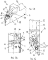
- FIGS. 1A-1E showing a cutting tool 10 having a coolant conduit 11 in accordance with an aspect of the present invention.
- the shown cutting tool 10 may be a turning tool for external metal machining, preferably for use in a Swiss-type lathe.
- a Swiss-type lathe is a variety of turning machine that feeds the stock through a guide bushing. This means the turning tool can always cut the stock near the bushing, and therefore close to the point of support, no matter how long the workpiece. The machine feeds the work out of the spindle and past the tool as it moves. This makes the CNC Swiss-type particularly effective for long and slender turned parts.
- the turning tool is stationary and the workpiece advances.
- a cutting tool for a Swiss-type lathe is relatively small, for example less than 20 cm from end to end and less than 3 cm in height.
- a cutting insert 20 suitable for the cutting tool can be of a single-sided (positive) geometry with a height H ( FIG. 1D ) where a clearance surface forms an obtuse angle with a lower face of the cutting insert.
- a suitable cutting insert for the cutting tool can be of a double-sided (negative) geometry where the clearance surface forms 90° angle with the lower fa ce of the cutting insert.
- the cutting tool 10 comprises a tool holder body 14 having a shank portion 12 and a head portion 13 at a free end thereof.
- the shank portion is elongate and supposed to be secured to a tool post in a lathe.
- the shank portion may have a rectangular cross-section such as square.
- the shank portion defines a horizontal midplane M.
- the shank portion and the head portion are usually made as a one-piece unit or monobloc.
- the monobloc is normally made from steel.
- the head portion 13 has a seat 15 having at least one bottom surface 16, preferably extending parallel to the midplane M.
- the bottom surface may have a recess 17 to accommodate a locking member, such as a screw 18.
- the cutting insert 20 may have a through hole or mounting hole and the recess 17 may have a radius R1.
- the bottom surface may be provided on a removable shim, not shown.
- a forward end of the head portion may terminate in a pointed portion (see Fig. 1E ).
- the pointed portion in the top view is defined by sides 25 and 26.
- the sides 25 and 26 (or cutting insert sides shown in phantom in FIG. 1E ) define an angle ⁇ that is 110° or less. That angle is divided by a bi sector B. Usually the same line bisects the active cutting corner of the cutting insert.
- the seat 15 is bordered to one side by a first wall 19.
- a first convex wall may at least partially be constituted by a first pin 21, which is provided in or inserted into a bore or first cavity 22 that communicates with the wall 19 or is open lengthwise towards the cutting insert.
- the pin has a convexly curved outer peripheral surface formed by any of a large number of shapes, e.g., cylindrical.
- the pin 21 is made of a material, such as hardened steel or cemented carbide, having higher hardness than the material of the tool holder body 14.
- the cavity 22 is a boring, which extends parallel or substantially parallel to the bottom surface 16.
- the cavity 22 breaks through or intersects the wall 19, and a small portion of the outer periphery of the pin 21 projects through the cavity 22 and thus extends past the wall 19 and into the seat in a direction towards the cutting insert.
- the pin projects a distance, which is at most 40% of the diameter of the pin.
- the pin 21 is adapted to present a line of contact in relation to the cutting insert 20 that is parallel or substantially parallel to the bottom surface or the midplane M.
- the line of contact is spaced from the bottom surface or a shim corresponding to about a half of the thickness of a suitable cutting insert 20.
- the pin may be inserted into the cavity 22 with press fit and/or by deforming material of the holder around the pin.
- the seat comprises a second convex wall to define a stationary and well-defined contact in relation to the cutting insert, preferably along a line of contact.
- the second convex wall may be constituted by a second pin 23 inserted into a bore or second cavity 24 opening into the bottom surface 16.
- the second cavity or boring or hole and the second pin may each have a center axis extending perpendicularly or substantially ( ⁇ 11°) perpendicularly to the bottom surface.
- the second cavity 24, and thus the pin 23, inclines at an angle ⁇ relative to a normal to the at least one bottom surface 16 that is 0 to 11°, see FIG. 1B , where 0° implies perpendicular relationship to the bottom surface.
- the expression "or substantially perpendicularly to the at least one bottom surface”, here means that the angle is in the range of 90°and 79°, i.e. the latter being 90°-11°.
- the second pin 23 extends deeper into the head portion 13 than a height of an exposed part thereof that protrudes above the bottom surface 16 for increased stability. An extension of the second pin 23 extends to a side of the coolant conveying member 29 to be accessible for being drilled.
- the bottom surface 16 may be flat all around the second cavity 24 or the second pin 23.
- the second pin center axis usually extends perpendicularly to the bottom surface if the cutting insert to be used is negative.
- the second pin 23 is located at an opposite side of the bisector B relative to a major portion of the first pin 21; the major portion being at least 90% of the first pin 21.
- the second pin When inserted into the hole 24 the second pin will protrude from the bottom surface a distance that is smaller than the height H of the cutting insert.
- a perpendicular distance between the free end of the second pin 23 (or 23' or 23") and the associated cutting edge is depicted by h in FIG.2D . This will make sure that the pin does not reach a cutting edge and therefore cannot damage or negatively influence the cutting edge.
- the second pin 23 when viewed as in FIG. 1D will intersect a projection of the first pin 21.
- a center axis of the first pin 21 may be positioned at a level of a free or top end of the second pin 23 when viewed as in FIG. 1D .
- the second pin 23 is adapted to present a line of contact in relation to the cutting insert 20 that is perpendicular or substantially perpendicular to the bottom surface or the midplane M.
- convex walls comprise separate pins 21 and 23, which are perpendicular or substantially perpendicular to each other when seen in a side view as in FIG. 1D .
- the first pin 21 is adapted to present a line of contact in relation to the cutting insert 20 that is parallel or substantially parallel to the bottom surface 16 and the second pin 23 is adapted to present a line of contact in relation to the cutting insert 20 that is perpendicular or substantially perpendicular to the bottom surface.
- the pins 21 and 23 may be identical or at least of the same diameter such that drilling of the cavities 22, 24 can be facilitated or expedited.
- the pins 21 and 23 are not meant to be adjustable, i.e. they are usually fixed in position.
- the first convex wall or the first pin 21 and the second convex wall or the second pin 23 may receive a wedge of a cutting insert that form an included angle that is 110° or less, for example 55° or not under 40° to be able to hold also narrow cutting inserts. Stated another way, tangents to the first convex wall 21 and the second convex wall 23 may form an angle ⁇ that is 110° or less.
- the second pin 23 may be located to abut at about a quarter of a greatest diagonal length of the cutting insert from an inactive cutting corner (depicted by 27 in FIG. 1E ).
- the head portion 13 is provided with an integral coolant conveying member 29 such as an integral nozzle, inducer or roof portion, i.e. the coolant conveying member is integral with the tool holder body, which is immovable or not able to be removed without destroying the original construction of the head portion.
- the coolant conveying member may completely or partially or at least partially overlie or cover the cutting insert when viewed in top view as best seen in FIG. 1C .
- a normal N to the at least one bottom surface 16 or the upper surface of the cutting insert 20 intersects the coolant conveying member 29, such that the coolant conveying member at least partially cover or overlies the cutting insert.
- the coolant conveying member 29 does not clamp on the cutting insert and is thus spaced from the upper surface 28 of the cutting insert by a distance A in the range of 0.2 to 3 mm in the direction of the normal N, such that the conveying member overhangs the cutting insert.
- a lower side of the coolant conveying member 29 forms a slot with the bottom surface 16, wherein the smallest width of the slot is greater than a thickness of the cutting insert 20 including any shim.
- the relative position between the coolant conveying member and the insert seat is constant.
- the coolant conveying member is spaced both from clamping means such as the locking member 18, and the cutting insert 20 when viewed in side view as shown in FIG. 1D .
- the coolant conveying member thus has a non-clamping function.
- the front face 30 of the coolant conveying member 29 contains an opening 31, which communicates with a coolant channel 32 that is generally directed towards the active cutting corner of the cutting insert.
- the coolant channel 32 slopes towards the opening 31 from a higher point where it connects to a vertical passage 33 that in turn connects to the coolant conduit 11.
- the coolant conduit 11 is in communication with a coolant source, not shown.
- the vertical passage 33 may be plugged at a lower end.
- the front face 30 may be located in a plane P intersecting the bottom surface 16 and/or the cutting insert 20 ( FIG. 1C ).
- the plane P may be parallel to the normal N.
- the plane P may intersect the bottom surface 16 at a distance from the radius center of the hole 17 that is less than 3 times the radius R1.
- the roof portion 29 is arranged spaced apart from an extension of the hole 17.
- the tool holder may have least one further coolant channel 34 that is provided below the bottom surface 16 for directing coolant towards a clearance face of the cutting insert 20.
- the channel 34 connects to the vertical passage 33 via a boring that is plugged at one end.
- coolant may flow from the coolant source in order through the coolant conduit 11 in the shank 12, the vertical passage 33, the coolant channel 32 and from the opening 31 to at least one active cutting edge.
- a jet stream of coolant is discharged from a second opening of the least one further coolant channel 34 below the bottom surface 16.
- the tool is mounted as follows.
- the cutting insert 20 is placed against the bottom surface 16 of the seat 15 and pushed inwardly such that converging sides of the cutting insert abut the convex wall 21 and 23, respectively.
- the screw 18 is moved through the hole in the cutting insert and is threaded firmly into the recess 17. Thereby, the cutting insert is secured to the seat 15. Typically, the screw 18 is caused to mate with the threaded hole in the bottom surface.
- the threaded hole is ordinarily formed in the bottom surface in a location such that, when the threaded shaft of the screw is inserted through the mounting hole in the insert and screwed into the threaded hole, there is a slight offset of a longitudinal axis of the threaded shaft of the screw in a direction toward the convex walls of the seat from the location of the axis of the mounting hole. Nonetheless, the lower surface of the insert and the bottom surface 16 (both of which are typically flat) can be caused to lie flat against one another. As the screw is screwed further into the threaded hole, a head of the screw urges bottom and sides of the insert 20 into more complete contact with the bottom and convex walls of the seat.
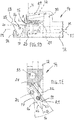
- FIGS. 2A to 2G showing a cutting tool 10' having a coolant conduit 11' in accordance with another aspect of the present invention.
- the drawings have been annotated with like numerals that indicate similar elements as in the previous described embodiment.
- the shown cutting tool 10' may be a turning tool for external metal machining, preferably for use in a Swiss-type lathe as discussed above.
- a cutting tool for a Swiss-type lathe is relatively small, for example less than 20 cm from end to end and less than 3 cm in height.
- the main difference from the previously described embodiment lies in the use of two coolant channels 32A' and 32B' in the coolant conveying member 29'.
- the front face 30' of the coolant conveying member 29' contains two openings 31', which each communicates with a coolant channel 32A', 32B' that is generally directed towards the active cutting corner of the cutting insert.
- the coolant channels 32' slope towards the openings 31' from a higher point where they connect to a vertical passage 33' that in turn connects to the coolant conduit 11'.
- the vertical passage 33' supplies fluid via a horizontal bore intersecting the inner ends of the coolant channels to the openings 31'.
- the horizontal bore is plugged by a screw 35'.
- the coolant conduit 11' is in communication with a coolant source, not shown.
- the openings 31' in the front face 30' may be located in a plane P' intersecting the bottom surface 16' and/or the cutting insert 20' ( FIG. 1C ).
- the plane P' may be parallel to the normal N'.
- the cutting insert 20' may have a through hole or mounting hole and the recess 17' may have a radius R1'.
- the directions of the coolant channels 32A', 32B' converge towards the cutting area.
- the first pin 21' is adapted to present a line of contact in relation to the cutting insert 20' that is parallel or substantially parallel to the at least one bottom surface 16' and the second pin 23' is adapted to present a line of contact in relation to the cutting insert 20' that is perpendicular or substantially perpendicular ( ⁇ 11°) to the at least one bottom surface.
- the second pin 23' extends deeper into the head portion 13' than a height of an exposed part thereof that protrudes above the bottom surface.
- An extension of the second pin 23' extends to a side of the coolant conveying member 29'.
- the bottom surface 16' may be flat all around the second cavity 24' or the second pin 23'.
- Tool life generally increases with increase in coolant supply pressure. This can be attributed to the ability of the high-pressure coolant to lift the chip and gain access closer to the cutting interface. This action leads to a reduction of the seizure region, thus lowering the friction coefficient, which in turn results in reduction in cutting temperature and cutting forces.
- the pressure used in the discussed embodiments is above 30 bar, preferably above 100 bar coolant pressure.
- the present invention facilitates seat production while having a coolant opening fixed close to the active cutting area. There is a limited need for spare parts because the coolant nozzle is built into the tool holder design and therefore handling of small tools is facilitated.
- the invention is applicable for all types of insert seats such as for turning, milling, drilling and boring.
Landscapes
- Engineering & Computer Science (AREA)
- Mechanical Engineering (AREA)
- Cutting Tools, Boring Holders, And Turrets (AREA)
Claims (15)
- Outil de coupe comprenant,
un corps de support d'outil (14 ; 14') présentant une partie de queue (12 ; 12') et une partie de tête (13 ; 13') ;
la partie de tête présentant un siège pour plaquette (15 ; 15'), où une plaquette de coupe (20 ; 20') est montée de manière détachable au moyen d'un élément de verrouillage (18 ; 18'), le siège comprenant au moins une surface inférieure (16 ; 16') sur laquelle la plaquette de coupe repose, où un élément d'acheminement de réfrigérant (29 ; 29') est intégré au corps de support d'outil, et où
une normale (N ; N') à la au moins une surface inférieure (16 ; 16') coupe l'élément d'acheminement de réfrigérant, de telle sorte que l'élément d'acheminement de réfrigérant couvre au moins en partie la plaquette de coupe, caractérisé en ce que l'élément d'acheminement de réfrigérant (29 ; 29') est espacé de l'élément de verrouillage (18 ; 18') et de la plaquette de coupe (20 ; 20') lorsqu'ils sont observés selon une vue de côté. - Outil selon la revendication 1, où l'outil de coupe (10 ; 10') présente un conduit à réfrigérant (11 ; 11'), et où l'élément d'acheminement de réfrigérant (29 ; 29') comprend au moins un canal à réfrigérant (32 ; 32') en communication d'écoulement avec le conduit à réfrigérant, le au moins un canal à réfrigérant débouchant dans une face avant (30 ; 30') de l'élément d'acheminement de réfrigérant intégré (29 ; 29').
- Outil selon la revendication 2, dans lequel la face avant (30 ; 30') est positionnée dans un plan (P ; P') coupant la surface inférieure (16 ; 16') et/ou la plaquette de coupe (20 ; 20').
- Outil selon l'une quelconque des revendications 1 à 3, dans lequel la surface inférieure (16 ; 16') présente un orifice (17 ; 17') ayant un rayon (R1 ; R1').
- Outil selon la revendication 4, dans lequel le plan (P ; P') coupe la surface inférieure (16 ; 16') à une distance du centre de rayon du trou (17 ; 17') qui est inférieure à 3 fois le rayon (R1 ; R1').
- Outil selon l'une quelconque des revendications précédentes, dans lequel au moins un canal à réfrigérant (34 ; 34') est prévu sous la surface inférieure (16 ; 16') de sorte à diriger un réfrigérant vers une face de dépouille de la plaquette de coupe (20 ; 20').
- Outil selon l'une quelconque des revendications précédentes, dans lequel l'élément d'acheminement de réfrigérant (29') présente deux canaux à réfrigérant (32A', 32B') dirigés vers un coin de coupe actif de la plaquette de coupe.
- Outil selon l'une quelconque des revendications précédentes, dans lequel le siège (15 ; 15') comprend une première paroi convexe (19 ; 19') et une deuxième paroi convexe.
- Outil selon la revendication 8, dans lequel des tangentes à la première paroi convexe (19 ; 19') et à la deuxième paroi convexe forment un angle (α) qui est de 110° ou moins.
- Outil selon la revendication 8 ou 9, dans lequel au moins une des parois convexes est située sur une broche (21, 23 ; 21', 23').
- Outil selon la revendication 8, 9 ou 10, dans lequel les parois convexes sont situées sur des première et deuxième broches séparées (21, 23 ; 21', 23'), lesquelles sont perpendiculaires ou sensiblement perpendiculaires l'une par rapport à l'autre lorsqu'elles sont observées selon la vue de côté.
- Outil selon la revendication 11, dans lequel chaque broche (21, 23 ; 21', 23') est montée de manière stationnaire sur la queue et est formée d'un matériau plus dur que la queue.
- Outil selon l'une quelconque des revendications 11 et 12, dans lequel la deuxième broche (23 ; 23') s'étend plus profondément dans la partie de tête (13 ; 13') qu'une hauteur d'une partie exposée de celle-ci qui dépasse au-dessus de la surface inférieure (16 ; 16').
- Outil selon l'une quelconque des revendications 11 à 13, dans lequel la surface inférieure (16 ; 16') est plane tout autour de la deuxième broche (23 ; 23').
- Outil selon l'une quelconque des revendications 1 à 14, dans lequel l'élément d'acheminement de réfrigérant (29 ; 29') surplombe la plaquette de coupe et est espacé de la surface supérieure (28 ; 28') de la plaquette de coupe d'une distance (A ; A') dans la plage de 0,2 à 3 mm dans la direction de la normale (N ; N').
Applications Claiming Priority (3)
| Application Number | Priority Date | Filing Date | Title |
|---|---|---|---|
| EP16153286.6A EP3199274B1 (fr) | 2016-01-29 | 2016-01-29 | Outil de découpage |
| EP16153283.3A EP3199273A1 (fr) | 2016-01-29 | 2016-01-29 | Outil de découpage |
| PCT/EP2017/050601 WO2017129414A1 (fr) | 2016-01-29 | 2017-01-12 | Outil de coupe |
Publications (2)
| Publication Number | Publication Date |
|---|---|
| EP3408048A1 EP3408048A1 (fr) | 2018-12-05 |
| EP3408048B1 true EP3408048B1 (fr) | 2020-03-11 |
Family
ID=57749977
Family Applications (1)
| Application Number | Title | Priority Date | Filing Date |
|---|---|---|---|
| EP17700089.0A Active EP3408048B1 (fr) | 2016-01-29 | 2017-01-12 | Outil de découpage |
Country Status (5)
| Country | Link |
|---|---|
| US (2) | US20190030613A1 (fr) |
| EP (1) | EP3408048B1 (fr) |
| KR (2) | KR102613108B1 (fr) |
| CN (2) | CN108472736B (fr) |
| WO (2) | WO2017129413A1 (fr) |
Families Citing this family (18)
| Publication number | Priority date | Publication date | Assignee | Title |
|---|---|---|---|---|
| WO2018139401A1 (fr) * | 2017-01-24 | 2018-08-02 | 京セラ株式会社 | Outil de coupe et procédé de production d'article coupé |
| JP7104055B2 (ja) * | 2017-10-06 | 2022-07-20 | 京セラ株式会社 | 切削工具及び切削加工物の製造方法 |
| DE102018100783B4 (de) | 2018-01-15 | 2025-11-13 | Kennametal Inc. | Drehwerkzeughalter sowie Drehwerkzeug |
| WO2019211043A1 (fr) * | 2018-04-30 | 2019-11-07 | Hartmetall-Werkzeugfabrik Paul Horn Gmbh | Outil d'usinage d'une pièce par enlèvement de copeaux |
| EP3623083B1 (fr) * | 2018-09-11 | 2022-11-09 | Walter Ag | Outil de tournage |
| KR102840280B1 (ko) * | 2019-05-20 | 2025-07-30 | 이스카 엘티디. | 고속-이송 선삭 공구 어셈블리 |
| GB2584296B (en) * | 2019-05-28 | 2022-04-13 | Gkn Aerospace Sweden Ab | An apparatus and method for machining an aeronautical component |
| EP3868500B1 (fr) * | 2020-02-20 | 2024-07-17 | Walter Ag | Outil de tournage |
| TWI718014B (zh) * | 2020-02-26 | 2021-02-01 | 昇益興企業有限公司 | 車刀及包括該車刀之車刀結構 |
| EP3956091A1 (fr) * | 2020-03-09 | 2022-02-23 | Muri Invest & Management UG | Outil de coupe et élément de compensation de distance pour le positionnement d'inserts de coupe re-dépolis dans un outil de coupe |
| EP3903973B1 (fr) * | 2020-04-27 | 2022-12-21 | Seco Tools Ab | Outil de coupe de métal avec buse pour la fourniture d'un fluide de refroidissement sur un bord de coupe |
| EP4169642A4 (fr) * | 2020-06-17 | 2023-08-02 | Sumitomo Electric Hardmetal Corp. | Mécanisme d'alimentation en liquide de refroidissement |
| CZ2020594A3 (cs) * | 2020-11-03 | 2022-06-01 | Západočeská Univerzita V Plzni | Nástroj pro obrábění |
| JP6961151B1 (ja) * | 2021-03-23 | 2021-11-05 | 株式会社タンガロイ | 旋削工具 |
| CZ309545B6 (cs) * | 2021-12-23 | 2023-03-29 | Západočeská Univerzita V Plzni | Nástroj pro obrábění |
| US12202050B2 (en) | 2021-12-29 | 2025-01-21 | Kennametal Inc. | Turning toolholder with enhanced coolant delivery system |
| CN115179102B (zh) * | 2022-06-20 | 2023-06-20 | 大连理工大学 | 一种用于精密车削加工的内冷系统及控制方法 |
| TWI863633B (zh) * | 2023-10-18 | 2024-11-21 | 莊松燁 | 機械加工用切削工具 |
Family Cites Families (47)
| Publication number | Priority date | Publication date | Assignee | Title |
|---|---|---|---|---|
| US1217585A (en) * | 1914-04-02 | 1917-02-27 | Submarine Signal Co | Method for measuring distance. |
| US3102326A (en) * | 1960-04-20 | 1963-09-03 | Alfred R Conti | Cutting tool |
| GB1003352A (en) * | 1963-02-19 | 1965-09-02 | Firth Brown Tools Ltd | Improvements in milling cutters |
| US3163920A (en) * | 1964-03-18 | 1965-01-05 | Willeys S Carbide Tool Company | Milling cutter with throwaway cutting inserts |
| GB1107634A (en) * | 1965-07-01 | 1968-03-27 | Ass Elect Ind | Improvements in or relating to turning and boring tools with replaceable tips |
| BE793105A (fr) * | 1971-12-24 | 1973-04-16 | Walter Gmbh Montanwerke | Outil de fraisage a plaquettes de coupe echangeables |
| US3889330A (en) * | 1974-06-19 | 1975-06-17 | Valeron Corp | Lateral lock indexable insert cutting tool |
| US4008631A (en) * | 1975-01-27 | 1977-02-22 | Cincinnati Milacron-Heald Corporation | Machine tool |
| US4174916A (en) * | 1978-04-24 | 1979-11-20 | Precision Industries, Inc. | Forming tool construction |
| US4202650A (en) * | 1978-10-13 | 1980-05-13 | Kennametal Inc. | Shim lock toolholder |
| SU1016082A1 (ru) * | 1982-01-04 | 1983-05-07 | Сестрорецкий Инструментальный Завод Им.Воскова | Режущий инструмент |
| US4791840A (en) * | 1984-02-29 | 1988-12-20 | United Technologies Corporation | Metal cutting with high pressure coolant |
| DE3520179C2 (de) * | 1985-06-05 | 1994-05-11 | Frits Weyler | Maschinenreibahle mit einstellbarer Wendeschneidplatte |
| FR2651703B1 (fr) * | 1989-09-14 | 1994-06-17 | Electro Metallurg Ste Indle | Dispositif de reglage micrometrique d'une plaquette de coupe sur un porte-outil. |
| JPH0596444A (ja) * | 1991-03-29 | 1993-04-20 | Tama Seimitsu Kk | バイトホルダー |
| JP3057952B2 (ja) * | 1993-03-04 | 2000-07-04 | 三菱マテリアル株式会社 | 旋削工具 |
| JPH0825109A (ja) * | 1994-07-20 | 1996-01-30 | Mitsubishi Materials Corp | 切削工具 |
| JPH08257807A (ja) * | 1995-03-24 | 1996-10-08 | Toshiba Tungaloy Co Ltd | 給油穴付きのバイト |
| JPH1094904A (ja) * | 1996-09-19 | 1998-04-14 | Toshiba Tungaloy Co Ltd | スローアウェイ式バイト |
| JP3489412B2 (ja) * | 1997-02-25 | 2004-01-19 | 三菱マテリアル株式会社 | 油穴付きバイト |
| US5873684A (en) * | 1997-03-29 | 1999-02-23 | Tool Flo Manufacturing, Inc. | Thread mill having multiple thread cutters |
| US6045300A (en) * | 1997-06-05 | 2000-04-04 | Antoun; Gregory S. | Tool holder with integral coolant passage and replaceable nozzle |
| US20020189413A1 (en) * | 2001-05-31 | 2002-12-19 | Zbigniew Zurecki | Apparatus and method for machining with cryogenically cooled oxide-containing ceramic cutting tools |
| SE523405C2 (sv) * | 2001-12-21 | 2004-04-13 | Seco Tools Ab | Verktyg för skärande bearbetning med ett avrundat hårt element i en stödyta i hållaren. |
| US7014393B2 (en) * | 2003-02-07 | 2006-03-21 | Dr. Joerg Guehring | Clamping and adjustment apparatus for a cutting tool |
| DE10331077B3 (de) * | 2003-07-09 | 2005-02-17 | Ernst Graf | Drehmeißelhalter |
| JP2005081459A (ja) * | 2003-09-05 | 2005-03-31 | Tungaloy Corp | 油穴付き切削工具 |
| JP2006055917A (ja) * | 2004-08-17 | 2006-03-02 | Tungaloy Corp | スローアウェイ式バイト |
| GB0501134D0 (en) * | 2005-01-20 | 2005-02-23 | Rolls Royce Plc | Cutting tool |
| US7429150B2 (en) * | 2006-05-31 | 2008-09-30 | Kennametal Inc. | Tool holder with spherical contact points |
| SE530581C2 (sv) * | 2006-11-28 | 2008-07-08 | Sandvik Intellectual Property | Verktyg och grundkropp för spånavskiljande innefattande två kanaler för en fluid |
| IL182078A (en) * | 2007-03-20 | 2011-09-27 | Iscar Ltd | System for attaching a cutting member to a cutter |
| US20090010722A1 (en) * | 2007-07-05 | 2009-01-08 | Hsin-Tien Chang | Boring Bar Allowing Direct Tuning |
| DE102008006262B4 (de) * | 2008-01-25 | 2009-11-26 | Präzisions-Drehteile Löcher GmbH | Zerspanungswerkzeug |
| DE202008003866U1 (de) * | 2008-01-25 | 2008-05-29 | Präzisions-Drehteile Löcher GmbH | Zerspanungswerkzeug |
| IL197095A (en) * | 2009-02-17 | 2013-02-28 | Iscar Ltd | Cutting tool having a retractable nozzle |
| DE102009060046A1 (de) * | 2009-12-21 | 2011-06-22 | Aleit GmbH, 35239 | System aus Werkzeugaufnahme und verstellbaren Werkzeug mit interner Kühlschmiermediumzufuhr |
| IL206283A0 (en) * | 2010-06-10 | 2010-11-30 | Iscar Ltd | Cutting tool and nozzle therefor |
| NO333697B1 (no) * | 2011-03-11 | 2013-08-26 | Teeness Asa | Anordning for innvendig sponskjaerende bearbeiding med en dyse for spyling av skjaervaeske mot skjaeret |
| US8826786B2 (en) * | 2012-02-23 | 2014-09-09 | Iscar, Ltd. | Cutting tool with internal fluid delivery system |
| US8876446B2 (en) * | 2012-03-28 | 2014-11-04 | Iscar, Ltd. | Cutting tool having clamping bolt provided with locking portion and cutting insert therefor |
| WO2014001447A1 (fr) * | 2012-06-28 | 2014-01-03 | Ceramtec Gmbh | Outil pour l'usinage par enlèvement de copeaux |
| US20140270999A1 (en) * | 2013-03-16 | 2014-09-18 | Hsien-Jen Huang | Coolant delivery device for cutting tools |
| US9656326B2 (en) * | 2013-04-24 | 2017-05-23 | Iscar, Ltd. | Tool holder having a clamping member with a non-circular cross-section and method for clamping a cutting insert therein |
| US9387538B2 (en) * | 2013-05-31 | 2016-07-12 | Ntm, Inc. | Tool holder for machine tool, machine tool assembly, and methods |
| EP3059034B1 (fr) * | 2013-10-18 | 2022-10-26 | Ngk Spark Plug Co., Ltd. | Porte-outil et outil de coupe |
| EP2946857B1 (fr) * | 2014-05-19 | 2019-10-16 | Sandvik Intellectual Property AB | Support d'outil de tournage et insert d'outil de coupe |
-
2017
- 2017-01-12 WO PCT/EP2017/050600 patent/WO2017129413A1/fr not_active Ceased
- 2017-01-12 CN CN201780006101.1A patent/CN108472736B/zh active Active
- 2017-01-12 US US16/073,468 patent/US20190030613A1/en not_active Abandoned
- 2017-01-12 KR KR1020187021021A patent/KR102613108B1/ko active Active
- 2017-01-12 WO PCT/EP2017/050601 patent/WO2017129414A1/fr not_active Ceased
- 2017-01-12 CN CN201780005010.6A patent/CN108472735B/zh active Active
- 2017-01-12 KR KR1020187021020A patent/KR102614838B1/ko active Active
- 2017-01-12 US US16/073,463 patent/US20190030612A1/en not_active Abandoned
- 2017-01-12 EP EP17700089.0A patent/EP3408048B1/fr active Active
Non-Patent Citations (1)
| Title |
|---|
| None * |
Also Published As
| Publication number | Publication date |
|---|---|
| CN108472736A (zh) | 2018-08-31 |
| WO2017129413A1 (fr) | 2017-08-03 |
| KR20180109885A (ko) | 2018-10-08 |
| CN108472736B (zh) | 2021-01-15 |
| KR20180109886A (ko) | 2018-10-08 |
| US20190030612A1 (en) | 2019-01-31 |
| US20190030613A1 (en) | 2019-01-31 |
| EP3408048A1 (fr) | 2018-12-05 |
| WO2017129414A1 (fr) | 2017-08-03 |
| KR102613108B1 (ko) | 2023-12-12 |
| CN108472735B (zh) | 2021-02-19 |
| CN108472735A (zh) | 2018-08-31 |
| KR102614838B1 (ko) | 2023-12-15 |
Similar Documents
| Publication | Publication Date | Title |
|---|---|---|
| US20190030612A1 (en) | Cutting tool | |
| US8696263B2 (en) | Cutting insert and cutting edge replaceable cutting tool | |
| US9925596B2 (en) | Turning tool holder and cutting tool insert | |
| JP6550759B2 (ja) | バイト | |
| KR100656265B1 (ko) | 인덱서블 절삭공구 | |
| US10654116B2 (en) | Cutting insert, metal spacer and holder | |
| KR20200020867A (ko) | 절삭 공구용 홀더 | |
| EP3059034A1 (fr) | Porte-outil et outil de coupe | |
| EP0534450A2 (fr) | Outil à couper le métal | |
| CN112122635B (zh) | 用于切削加工的工具 | |
| KR20140026172A (ko) | 내경 가공용 선삭 공구 | |
| US7862266B2 (en) | Cutting tool for machining a hole | |
| IL153536A (en) | Drilling tool | |
| KR20200127161A (ko) | 냉각제 채널을 포함하는 금속 절삭을 위한 선삭 공구 | |
| EP3199273A1 (fr) | Outil de découpage | |
| KR101011053B1 (ko) | 엔드밀 및 엔드밀용 절삭 삽입체 | |
| JP2006055917A (ja) | スローアウェイ式バイト | |
| EP3199274B1 (fr) | Outil de découpage | |
| US12434306B2 (en) | Cutting tool assembly | |
| US8641334B2 (en) | Insert | |
| JP2022155847A (ja) | ボーリングバー | |
| KR102961512B1 (ko) | 절삭 삽입물 및 가공용 공구 | |
| KR200291607Y1 (ko) | 여유각이 형성된 절삭공구의 네가티브 인서트 팁 | |
| KR200237150Y1 (ko) | 드릴기능이 부가된 엔드밀 | |
| JP2009125842A (ja) | 切削工具 |
Legal Events
| Date | Code | Title | Description |
|---|---|---|---|
| STAA | Information on the status of an ep patent application or granted ep patent |
Free format text: STATUS: UNKNOWN |
|
| STAA | Information on the status of an ep patent application or granted ep patent |
Free format text: STATUS: THE INTERNATIONAL PUBLICATION HAS BEEN MADE |
|
| PUAI | Public reference made under article 153(3) epc to a published international application that has entered the european phase |
Free format text: ORIGINAL CODE: 0009012 |
|
| STAA | Information on the status of an ep patent application or granted ep patent |
Free format text: STATUS: REQUEST FOR EXAMINATION WAS MADE |
|
| 17P | Request for examination filed |
Effective date: 20180829 |
|
| AK | Designated contracting states |
Kind code of ref document: A1 Designated state(s): AL AT BE BG CH CY CZ DE DK EE ES FI FR GB GR HR HU IE IS IT LI LT LU LV MC MK MT NL NO PL PT RO RS SE SI SK SM TR |
|
| AX | Request for extension of the european patent |
Extension state: BA ME |
|
| DAV | Request for validation of the european patent (deleted) | ||
| DAX | Request for extension of the european patent (deleted) | ||
| GRAP | Despatch of communication of intention to grant a patent |
Free format text: ORIGINAL CODE: EPIDOSNIGR1 |
|
| STAA | Information on the status of an ep patent application or granted ep patent |
Free format text: STATUS: GRANT OF PATENT IS INTENDED |
|
| INTG | Intention to grant announced |
Effective date: 20190927 |
|
| GRAS | Grant fee paid |
Free format text: ORIGINAL CODE: EPIDOSNIGR3 |
|
| GRAA | (expected) grant |
Free format text: ORIGINAL CODE: 0009210 |
|
| STAA | Information on the status of an ep patent application or granted ep patent |
Free format text: STATUS: THE PATENT HAS BEEN GRANTED |
|
| AK | Designated contracting states |
Kind code of ref document: B1 Designated state(s): AL AT BE BG CH CY CZ DE DK EE ES FI FR GB GR HR HU IE IS IT LI LT LU LV MC MK MT NL NO PL PT RO RS SE SI SK SM TR |
|
| REG | Reference to a national code |
Ref country code: GB Ref legal event code: FG4D |
|
| REG | Reference to a national code |
Ref country code: CH Ref legal event code: EP |
|
| REG | Reference to a national code |
Ref country code: AT Ref legal event code: REF Ref document number: 1242518 Country of ref document: AT Kind code of ref document: T Effective date: 20200315 |
|
| REG | Reference to a national code |
Ref country code: IE Ref legal event code: FG4D |
|
| REG | Reference to a national code |
Ref country code: DE Ref legal event code: R096 Ref document number: 602017012900 Country of ref document: DE |
|
| PG25 | Lapsed in a contracting state [announced via postgrant information from national office to epo] |
Ref country code: NO Free format text: LAPSE BECAUSE OF FAILURE TO SUBMIT A TRANSLATION OF THE DESCRIPTION OR TO PAY THE FEE WITHIN THE PRESCRIBED TIME-LIMIT Effective date: 20200611 Ref country code: FI Free format text: LAPSE BECAUSE OF FAILURE TO SUBMIT A TRANSLATION OF THE DESCRIPTION OR TO PAY THE FEE WITHIN THE PRESCRIBED TIME-LIMIT Effective date: 20200311 Ref country code: RS Free format text: LAPSE BECAUSE OF FAILURE TO SUBMIT A TRANSLATION OF THE DESCRIPTION OR TO PAY THE FEE WITHIN THE PRESCRIBED TIME-LIMIT Effective date: 20200311 |
|
| REG | Reference to a national code |
Ref country code: NL Ref legal event code: MP Effective date: 20200311 |
|
| PG25 | Lapsed in a contracting state [announced via postgrant information from national office to epo] |
Ref country code: GR Free format text: LAPSE BECAUSE OF FAILURE TO SUBMIT A TRANSLATION OF THE DESCRIPTION OR TO PAY THE FEE WITHIN THE PRESCRIBED TIME-LIMIT Effective date: 20200612 Ref country code: BG Free format text: LAPSE BECAUSE OF FAILURE TO SUBMIT A TRANSLATION OF THE DESCRIPTION OR TO PAY THE FEE WITHIN THE PRESCRIBED TIME-LIMIT Effective date: 20200611 Ref country code: HR Free format text: LAPSE BECAUSE OF FAILURE TO SUBMIT A TRANSLATION OF THE DESCRIPTION OR TO PAY THE FEE WITHIN THE PRESCRIBED TIME-LIMIT Effective date: 20200311 Ref country code: SE Free format text: LAPSE BECAUSE OF FAILURE TO SUBMIT A TRANSLATION OF THE DESCRIPTION OR TO PAY THE FEE WITHIN THE PRESCRIBED TIME-LIMIT Effective date: 20200311 Ref country code: LV Free format text: LAPSE BECAUSE OF FAILURE TO SUBMIT A TRANSLATION OF THE DESCRIPTION OR TO PAY THE FEE WITHIN THE PRESCRIBED TIME-LIMIT Effective date: 20200311 |
|
| REG | Reference to a national code |
Ref country code: LT Ref legal event code: MG4D |
|
| PG25 | Lapsed in a contracting state [announced via postgrant information from national office to epo] |
Ref country code: NL Free format text: LAPSE BECAUSE OF FAILURE TO SUBMIT A TRANSLATION OF THE DESCRIPTION OR TO PAY THE FEE WITHIN THE PRESCRIBED TIME-LIMIT Effective date: 20200311 |
|
| PG25 | Lapsed in a contracting state [announced via postgrant information from national office to epo] |
Ref country code: EE Free format text: LAPSE BECAUSE OF FAILURE TO SUBMIT A TRANSLATION OF THE DESCRIPTION OR TO PAY THE FEE WITHIN THE PRESCRIBED TIME-LIMIT Effective date: 20200311 Ref country code: SM Free format text: LAPSE BECAUSE OF FAILURE TO SUBMIT A TRANSLATION OF THE DESCRIPTION OR TO PAY THE FEE WITHIN THE PRESCRIBED TIME-LIMIT Effective date: 20200311 Ref country code: LT Free format text: LAPSE BECAUSE OF FAILURE TO SUBMIT A TRANSLATION OF THE DESCRIPTION OR TO PAY THE FEE WITHIN THE PRESCRIBED TIME-LIMIT Effective date: 20200311 Ref country code: PT Free format text: LAPSE BECAUSE OF FAILURE TO SUBMIT A TRANSLATION OF THE DESCRIPTION OR TO PAY THE FEE WITHIN THE PRESCRIBED TIME-LIMIT Effective date: 20200805 Ref country code: CZ Free format text: LAPSE BECAUSE OF FAILURE TO SUBMIT A TRANSLATION OF THE DESCRIPTION OR TO PAY THE FEE WITHIN THE PRESCRIBED TIME-LIMIT Effective date: 20200311 Ref country code: SK Free format text: LAPSE BECAUSE OF FAILURE TO SUBMIT A TRANSLATION OF THE DESCRIPTION OR TO PAY THE FEE WITHIN THE PRESCRIBED TIME-LIMIT Effective date: 20200311 Ref country code: IS Free format text: LAPSE BECAUSE OF FAILURE TO SUBMIT A TRANSLATION OF THE DESCRIPTION OR TO PAY THE FEE WITHIN THE PRESCRIBED TIME-LIMIT Effective date: 20200711 Ref country code: RO Free format text: LAPSE BECAUSE OF FAILURE TO SUBMIT A TRANSLATION OF THE DESCRIPTION OR TO PAY THE FEE WITHIN THE PRESCRIBED TIME-LIMIT Effective date: 20200311 |
|
| REG | Reference to a national code |
Ref country code: AT Ref legal event code: MK05 Ref document number: 1242518 Country of ref document: AT Kind code of ref document: T Effective date: 20200311 |
|
| REG | Reference to a national code |
Ref country code: DE Ref legal event code: R097 Ref document number: 602017012900 Country of ref document: DE |
|
| PLBE | No opposition filed within time limit |
Free format text: ORIGINAL CODE: 0009261 |
|
| STAA | Information on the status of an ep patent application or granted ep patent |
Free format text: STATUS: NO OPPOSITION FILED WITHIN TIME LIMIT |
|
| PG25 | Lapsed in a contracting state [announced via postgrant information from national office to epo] |
Ref country code: DK Free format text: LAPSE BECAUSE OF FAILURE TO SUBMIT A TRANSLATION OF THE DESCRIPTION OR TO PAY THE FEE WITHIN THE PRESCRIBED TIME-LIMIT Effective date: 20200311 Ref country code: ES Free format text: LAPSE BECAUSE OF FAILURE TO SUBMIT A TRANSLATION OF THE DESCRIPTION OR TO PAY THE FEE WITHIN THE PRESCRIBED TIME-LIMIT Effective date: 20200311 Ref country code: AT Free format text: LAPSE BECAUSE OF FAILURE TO SUBMIT A TRANSLATION OF THE DESCRIPTION OR TO PAY THE FEE WITHIN THE PRESCRIBED TIME-LIMIT Effective date: 20200311 |
|
| 26N | No opposition filed |
Effective date: 20201214 |
|
| PG25 | Lapsed in a contracting state [announced via postgrant information from national office to epo] |
Ref country code: PL Free format text: LAPSE BECAUSE OF FAILURE TO SUBMIT A TRANSLATION OF THE DESCRIPTION OR TO PAY THE FEE WITHIN THE PRESCRIBED TIME-LIMIT Effective date: 20200311 Ref country code: SI Free format text: LAPSE BECAUSE OF FAILURE TO SUBMIT A TRANSLATION OF THE DESCRIPTION OR TO PAY THE FEE WITHIN THE PRESCRIBED TIME-LIMIT Effective date: 20200311 |
|
| PG25 | Lapsed in a contracting state [announced via postgrant information from national office to epo] |
Ref country code: MC Free format text: LAPSE BECAUSE OF FAILURE TO SUBMIT A TRANSLATION OF THE DESCRIPTION OR TO PAY THE FEE WITHIN THE PRESCRIBED TIME-LIMIT Effective date: 20200311 |
|
| REG | Reference to a national code |
Ref country code: CH Ref legal event code: PL |
|
| PG25 | Lapsed in a contracting state [announced via postgrant information from national office to epo] |
Ref country code: LU Free format text: LAPSE BECAUSE OF NON-PAYMENT OF DUE FEES Effective date: 20210112 |
|
| REG | Reference to a national code |
Ref country code: BE Ref legal event code: MM Effective date: 20210131 |
|
| PG25 | Lapsed in a contracting state [announced via postgrant information from national office to epo] |
Ref country code: CH Free format text: LAPSE BECAUSE OF NON-PAYMENT OF DUE FEES Effective date: 20210131 Ref country code: LI Free format text: LAPSE BECAUSE OF NON-PAYMENT OF DUE FEES Effective date: 20210131 |
|
| PG25 | Lapsed in a contracting state [announced via postgrant information from national office to epo] |
Ref country code: IE Free format text: LAPSE BECAUSE OF NON-PAYMENT OF DUE FEES Effective date: 20210112 |
|
| PG25 | Lapsed in a contracting state [announced via postgrant information from national office to epo] |
Ref country code: BE Free format text: LAPSE BECAUSE OF NON-PAYMENT OF DUE FEES Effective date: 20210131 |
|
| PG25 | Lapsed in a contracting state [announced via postgrant information from national office to epo] |
Ref country code: CY Free format text: LAPSE BECAUSE OF FAILURE TO SUBMIT A TRANSLATION OF THE DESCRIPTION OR TO PAY THE FEE WITHIN THE PRESCRIBED TIME-LIMIT Effective date: 20200311 |
|
| P01 | Opt-out of the competence of the unified patent court (upc) registered |
Effective date: 20230603 |
|
| PG25 | Lapsed in a contracting state [announced via postgrant information from national office to epo] |
Ref country code: HU Free format text: LAPSE BECAUSE OF FAILURE TO SUBMIT A TRANSLATION OF THE DESCRIPTION OR TO PAY THE FEE WITHIN THE PRESCRIBED TIME-LIMIT; INVALID AB INITIO Effective date: 20170112 |
|
| PG25 | Lapsed in a contracting state [announced via postgrant information from national office to epo] |
Ref country code: MK Free format text: LAPSE BECAUSE OF FAILURE TO SUBMIT A TRANSLATION OF THE DESCRIPTION OR TO PAY THE FEE WITHIN THE PRESCRIBED TIME-LIMIT Effective date: 20200311 |
|
| PG25 | Lapsed in a contracting state [announced via postgrant information from national office to epo] |
Ref country code: TR Free format text: LAPSE BECAUSE OF FAILURE TO SUBMIT A TRANSLATION OF THE DESCRIPTION OR TO PAY THE FEE WITHIN THE PRESCRIBED TIME-LIMIT Effective date: 20200311 |
|
| PG25 | Lapsed in a contracting state [announced via postgrant information from national office to epo] |
Ref country code: MT Free format text: LAPSE BECAUSE OF FAILURE TO SUBMIT A TRANSLATION OF THE DESCRIPTION OR TO PAY THE FEE WITHIN THE PRESCRIBED TIME-LIMIT Effective date: 20200311 |
|
| PGFP | Annual fee paid to national office [announced via postgrant information from national office to epo] |
Ref country code: GB Payment date: 20251204 Year of fee payment: 10 |
|
| PGFP | Annual fee paid to national office [announced via postgrant information from national office to epo] |
Ref country code: FR Payment date: 20251222 Year of fee payment: 10 |
|
| PGFP | Annual fee paid to national office [announced via postgrant information from national office to epo] |
Ref country code: DE Payment date: 20251203 Year of fee payment: 10 |
|
| PGFP | Annual fee paid to national office [announced via postgrant information from national office to epo] |
Ref country code: IT Payment date: 20251219 Year of fee payment: 10 |