EP3408108B1 - Procede de fabrication d'un panneau de decoration imprime - Google Patents
Procede de fabrication d'un panneau de decoration imprime Download PDFInfo
- Publication number
- EP3408108B1 EP3408108B1 EP17701147.5A EP17701147A EP3408108B1 EP 3408108 B1 EP3408108 B1 EP 3408108B1 EP 17701147 A EP17701147 A EP 17701147A EP 3408108 B1 EP3408108 B1 EP 3408108B1
- Authority
- EP
- European Patent Office
- Prior art keywords
- radiation
- printing
- carrier
- printing ink
- ink
- Prior art date
- Legal status (The legal status is an assumption and is not a legal conclusion. Google has not performed a legal analysis and makes no representation as to the accuracy of the status listed.)
- Active
Links
Images

Classifications
-
- B—PERFORMING OPERATIONS; TRANSPORTING
- B44—DECORATIVE ARTS
- B44C—PRODUCING DECORATIVE EFFECTS; MOSAICS; TARSIA WORK; PAPERHANGING
- B44C5/00—Processes for producing special ornamental bodies
- B44C5/04—Ornamental plaques, e.g. decorative panels, decorative veneers
- B44C5/043—Ornamental plaques, e.g. decorative panels, decorative veneers containing wooden elements
-
- B—PERFORMING OPERATIONS; TRANSPORTING
- B41—PRINTING; LINING MACHINES; TYPEWRITERS; STAMPS
- B41M—PRINTING, DUPLICATING, MARKING, OR COPYING PROCESSES; COLOUR PRINTING
- B41M7/00—After-treatment of prints, e.g. heating, irradiating, setting of the ink, protection of the printed stock
- B41M7/0081—After-treatment of prints, e.g. heating, irradiating, setting of the ink, protection of the printed stock using electromagnetic radiation or waves, e.g. ultraviolet radiation, electron beams
-
- B—PERFORMING OPERATIONS; TRANSPORTING
- B44—DECORATIVE ARTS
- B44C—PRODUCING DECORATIVE EFFECTS; MOSAICS; TARSIA WORK; PAPERHANGING
- B44C5/00—Processes for producing special ornamental bodies
- B44C5/04—Ornamental plaques, e.g. decorative panels, decorative veneers
-
- B—PERFORMING OPERATIONS; TRANSPORTING
- B44—DECORATIVE ARTS
- B44C—PRODUCING DECORATIVE EFFECTS; MOSAICS; TARSIA WORK; PAPERHANGING
- B44C1/00—Processes, not specifically provided for elsewhere, for producing decorative surface effects
- B44C1/24—Pressing or stamping ornamental designs on surfaces
-
- B—PERFORMING OPERATIONS; TRANSPORTING
- B44—DECORATIVE ARTS
- B44C—PRODUCING DECORATIVE EFFECTS; MOSAICS; TARSIA WORK; PAPERHANGING
- B44C5/00—Processes for producing special ornamental bodies
- B44C5/06—Natural ornaments; Imitations thereof
Definitions
- the present invention relates to a method for producing a printed decorative panel.
- the present invention relates in particular to a method for producing a printed decorative panel with radiation-curable ink, which method enables improved curing of the radiation-curable ink.
- Decorative panels for example for interior construction, are known per se. So far, such decorative panels have often been produced as laminates, in which a decorative paper pre-printed with a desired decoration is applied to a carrier plate, on which a so-called overlay is then applied. Furthermore, direct printing processes are known in which the carrier plate itself or a non-printed paper applied to the carrier plate is printed.
- a wear and / or cover layer within the meaning of the invention is a layer applied as an external finish, which in particular protects the decorative layer from wear and tear or damage from dirt, the influence of moisture or mechanical effects such as abrasion.
- wear or cover layers have a surface structure that matches the decor.
- a surface structure that matches the decor is understood to mean that the surface of the decorative panel has a haptically perceptible structure which corresponds in its shape and pattern to the applied decoration in order to obtain a replica of a natural material that is as true to the original as possible, also with regard to the feel.
- a problem that can arise when directly printing decorative panels is that the printed ink or the decor often has to be dried completely before further treatment steps in order to ensure a high quality of the decor. This can possibly reduce the production speed.
- Such a problem can apply equally to printing a paper applied to a carrier plate as well as to direct printing on the carrier plate.
- EP 1 918 108 A1 is particularly concerned with an ink composition and an ink jet printing process, particularly describing radiation curable compositions.
- the substrate to be printed is in particular paper, glass, plastic, films, metal and printed circuit boards. It is further generally described that the conditions used for the irradiation are selected based on the predetermined amount and thickness of the ink adhered to the substrate.
- US 2007/0040885 A1 describes a printing method and an arrangement for printing in particular a paper using radiation-curing ink.
- the ink has curing initiators that are active for radiation of different wavelengths, so that first partial curing and then final curing can take place.
- a control unit is provided which adjusts the radiation energy of a radiation unit as a function of the type of ink and the amount of ink applied to a substrate. The amount of ink is determined based on an image to be printed, that is, based on predetermined data.
- US 2012/0176436 A1 deals with a printing process for printing on paper, for example. It should be provided in particular that ink is applied to the substrate to be printed and irradiated from the opposite side in order to achieve curing of the ink. It is described that the amount of irradiation or the irradiation time is adjusted based on the amount of the ink applied to the substrate to be printed. This is done on the basis of predetermined print data. Taking this into account, the object of the present invention is to create a method for producing a decorative panel which is able to at least partially overcome at least one problem known from the prior art. In particular, it is the object of the present invention to provide a method for producing a decorative panel which allows an improved application of a decoration by means of a printing process.
- decorative panel is to be understood as meaning wall, ceiling, door or floor panels which have a decoration applied to a carrier plate.
- Decorative panels are used in a variety of ways both in the area of interior design of rooms and for decorative cladding of buildings, for example in trade fair construction.
- One of the most common areas of application for decorative panels is their use as flooring.
- the decor panels often have a decor that is intended to simulate a natural material.
- Examples of such modeled natural materials are types of wood such as maple, oak, birch, cherry, ash, walnut, chestnut, wenge or exotic woods such as panga-panga, Mahogany, bamboo and bubinga.
- natural materials such as stone surfaces or ceramic surfaces are often modeled on.
- direct printing is understood to mean the application of a decoration directly to the carrier of a panel or to an unprinted fiber material layer applied to the carrier.
- a decorative layer previously printed with a desired decor is applied to a carrier
- direct printing the decor is printed directly in the course of the surface coating or the panel production.
- Different printing techniques can be used that can work with printing inks, such as, in particular, digital printing techniques such as inkjet processes or laser printing processes.
- fiber materials includes materials such as e.g. To understand paper and nonwovens based on vegetable, animal, mineral or artificial fibers, as well as cardboard.
- fiber materials made from plant fibers are, in addition to papers and nonwovens made from cellulose fibers, panels made from biomass such as straw, corn stalks, bamboo, leaves, algae extracts, hemp, cotton or oil palm fibers.
- animal fiber materials are keratin-based materials such as Wool or horsehair.
- mineral fiber materials are made of mineral wool or glass wool.
- a plate-shaped carrier is initially provided in accordance with method step a).
- the carrier provided according to method step a) can be designed in a manner known per se for the production of decorative panels.
- the carrier can be made of different materials.
- the material of the carrier can be selected depending on the area of application.
- the carrier can consist of or have a wood material, provided that the decorative panel is not exposed to excessive moisture or weather conditions. If, on the other hand, the panel is to be used in damp rooms or outdoors, for example, the carrier can consist of or have a plastic.
- Wood-based materials within the meaning of the invention are, in addition to solid wood materials, also materials such as e.g. Cross laminated timber, glued laminated timber, cross laminated timber, laminated veneer plywood, laminated veneer lumber, veneer strip timber and flexible plywood.
- wood-based materials for the purposes of the invention also include wood-chip materials such as e.g. Chipboard, extruded board, coarse chipboard (Oriented Structural Board, OSB) and chipboard wood as well as wood fiber materials such as Wood fiber insulation boards (HFD), medium-hard and hard fiber boards (MB, HFH), and in particular medium-density fibreboard (MDF) and high-density fibreboard (HDF).
- wood fiber insulation boards HFD
- MB medium-hard and hard fiber boards
- MDF medium-density fibreboard
- HDF high-density fibreboard
- Modern wood-based materials such as wood-polymer materials (Wood Plastic Composite, WPC), sandwich panels made of a light core material such as foam, rigid foam or paper honeycomb and a layer of wood applied to it, as well as mineral, e.g. Wood-based panels for the purposes of the invention are bonded with cement. Cork also represents a wood material in the sense of the invention.
- WPC Wood Plastic Composite
- Plastics that can be used in the manufacture of the corresponding panels are, for example, thermoplastics such as polyvinyl chloride (PVC), polyolefins (e.g. polyethylene (PE), polypropylene (PP), polyamides (PA), polyurethanes (PU), polystyrene (PS)) , Acrylonitrile-butadiene-styrene (ABS), polymethyl methacrylate (PMMA), polycarbonate (PC), polyethylene terephthalate (PET), polyetheretherketone (PEEK) or mixtures or copolymers of these.
- PVC polyvinyl chloride
- PE polyolefins
- PE polyethylene
- PP polypropylene
- PA polyamides
- PU polyurethanes
- PS polystyrene
- ABS Acrylonitrile-butadiene-styrene
- PMMA polymethyl methacrylate
- PC polycarbonate
- PET polyethylene terephthalate
- a copolymer of polyethylene and polypropylene for example in a ratio of 1/1 can also be used, for example, a wood and a polymer which can be present in a ratio of 40/60 to 70/30, for example 50/50.
- Polypropylene, polyethylene or a copolymer of, for example, can be used as polymer components the two aforementioned Materials are used, furthermore wood flour can be used as a wood component.
- the plastics can in principle contain customary fillers, for example calcium carbonate (chalk), aluminum oxide, silica gel, quartz powder, wood flour, talc.
- mineral fillers can be advantageous.
- Talc or talc or calcium carbonate (chalk), aluminum oxide, silica gel, quartz powder, wood flour, gypsum are particularly suitable here.
- chalk can be provided.
- the proportion of mineral fillers, such as talc can be in a range from 30% by weight to 80% by weight, for example from 45% by weight to 70% by weight.
- the slip of the carrier can be improved by the fillers, in particular by the chalk. Using talc, for example, can enable improved heat resistance and moisture resistance to be achieved.
- talc can be used as a filler in a WPC material, for example with a wood component, for example wood fibers together with a plastic, as described above, or to form a pure plastic.
- the fillers can also be colored in a known manner.
- a mixture of talc and polypropylene can be present, in which talc is present in the aforementioned quantity range, approximately at 60% by weight.
- the plate material has a flame retardant.
- a carrier is provided with a decoration in a method described above.
- the carrier is printed using radiation-curable printing ink, as described in detail below.
- printing of the carrier can be implemented directly on the carrier or likewise encompassed by the present invention on a fibrous web or another suitable printing substrate of the carrier and thus indirectly on the carrier.
- printing on the carrier as well as applying a layer to the carrier or applying a material to the carrier can be understood to mean the direct printing of the carrier or the application of a layer directly to the carrier or the application of a material to the carrier indirectly to a layer on the carrier.
- the paper or nonwoven layer is first applied to the carrier and immediately printed or provided with a printing substrate and then printed.
- a resin layer which can serve as an adhesive for fixing the paper or fleece layer, can preferably be applied to the plate-shaped carrier after process step a) according to process step b).
- a resin composition known per se can be used in this process step.
- this method step can again be used through the use of application rollers.
- a resin composition which has at least one compound selected from the group consisting of melamine resin, formaldehyde resin, urea resin, phenolic resin, epoxy resin, unsaturated polyester resin, diallyl phthalate or mixtures thereof as resin component .
- the resin composition can, for example, be applied in an amount between 5 g / m 2 and 50 g / m 2 , preferably 10 g / m 2 and 40 g / m 2 be applied.
- the amount of the resin composition applied is particularly preferably selected such that the paper or nonwoven applied in the subsequent step c) is not completely soaked with the resin composition.
- the resin layer can be prevented from bleeding through before printing by selecting the type and amount of the applied resin layer.
- the resin composition is applied in step b) with a kinematic viscosity that corresponds to a flow time between ⁇ 10 s and ⁇ 40 s from a standard flow cup (measured in accordance with DIN 53211).
- the paper or fleece layer can be applied to the plate-shaped carrier or to the resin layer. It can be provided that in step c) a paper or fleece with a grammage between 30 g / m 2 and 80 g / m 2 , preferably between 40 g / m 2 and 70 g / m 2 on the plate-shaped carrier is applied.
- the application of the paper or the fleece can be implemented, for example, via suitable feed rollers which guide the paper or fleece in such a way that it is arranged on the carrier.
- the resulting layer structure can be calendered, in particular at a temperature between 40 ° and 250 ° C.
- This step can be carried out in a manner known per se by the method of the layer structure by a calender having calender rolls, which treats the layer structure with pressure and / or heat.
- the resin layer can remain uncured or, preferably, it can be partially or fully cured.
- the printing of the carrier according to method step e) takes place following the calendering according to method step c) or in Following the application of a printing substrate, in particular on the calendered layer structure, as described below.
- the following statements apply equally if a paper or fleece layer is dispensed with and the printing substrate is applied directly to the carrier.
- Such a printing substrate comprises, for example, a resin system, for example comprising a melamine resin.
- a successive double application of a resin composition in each case with the formation of two resin-containing layers can be carried out to produce the printing background using the following method steps: formation of a first resin-containing layer using a resin composition with a mixture of melamine resin and urea resin; and forming a second resin-containing layer using a resin composition with a proportion of melamine resin in the resin proportion which is in a range of 95% by weight, in particular 99% by weight.
- the printing substrate can be designed in one or more layers, each of the layers having or being able to consist of a resin component.
- the resin in each layer can include or consist of urea resin or melamine resin, so that the proportion of urea resin in the resin content can be, for example, from ⁇ 0% by weight to ⁇ 100, with the remainder being formed by melamine resin and / or where the proportion of melamine resin in the resin portion can be, for example, from 0% by weight to 100, with the remainder being formed, for example, by urea resin.
- the respective resin composition can in principle, for example, have a resin content between 15% by weight and 95% by weight, preferably between 20% by weight and 90% by weight, even more preferably between 25% by weight and Have ⁇ 65 wt .-%.
- the first resin-containing layer can be applied with a mixture which has only melamine resin and urea resin in the resin portion.
- Melamine resin can be present in the resin portion, for example, in a proportion that is in a range from 55% by weight to 90% by weight, for example 60% by weight to 80% by weight, about 70% by weight, is, wherein the remaining portion of the resin portion can each be formed by urea resin.
- the first resinous layer according to method step e1) can be applied in an amount which is smaller than the amount of the second resinous layer applied according to method step e2).
- a resin composition which, as a solid, contains at least one compound from the group consisting of titanium dioxide, barium sulfate, barium oxide, barium chromate, zirconium (IV) oxide, silicon dioxide, aluminum hydroxide, aluminum oxide, iron oxide, iron ( III. Has mercury sulfide, carbon black, graphite, cellulose fibers or mixtures of these.
- titanium dioxide barium sulfate, barium oxide, barium chromate, zirconium (IV) oxide, silicon dioxide, aluminum hydroxide, aluminum oxide, iron oxide, iron ( III. Has mercury sulfide, carbon black, graphite, cellulose fibers or mixtures of these.
- a printing background with a brown or brownish base tone can be applied, while with a decor design that is a light type of wood or a light stone
- a printing background with a yellow or white base tone should be applied.
- the use of cellulose fibers in the resin composition applied to the plate-shaped carrier shows in particular the advantageous effect that any irregularities on the carrier plate surface to which the resin composition is applied no longer show through to the surface to be printed later, which leads to a significant improvement in the printed image leads.
- Such irregularities can be, for example, grinding grooves from grinding the carrier plates or impressions from conveying means, such as, for example, conveyor belts etc.
- cellulose fibers When cellulose fibers are used, they preferably have a grain size in the range between> 10 ⁇ m and ⁇ 100 ⁇ m, in particular between 25 ⁇ m and 90 ⁇ m.
- the proportion of the cellulose fiber in the solid contained in the resin composition can, for example, be in a range between 0 0% by weight and 100% by weight, preferably between 40% by weight and 100% by weight., in particular between 60% by weight and 100% by weight. lie.
- the preferred proportion of solids in the resin composition when using cellulose fibers is at the lower end of the% by weight range, preferably between 0.5% by weight and 3.5% by weight, in particular between 1.0% by weight % and 2.5% by weight, whereas the preferred proportion of solids in the resin composition for the other solids listed as suitable, for example, is preferably between 5% by weight and 85% by weight, preferably between 10% by weight % and 80% by weight, even more preferably between 35% by weight and 75% by weight. This is due in particular to the low specific gravity of the cellulose fibers that can be added as solids in comparison to the specific gravity of the other solids listed.
- a resin composition which contains at least one organic or inorganic pigment selected from the group consisting of Prussian blue, brilliant yellow, cadmium yellow, cadmium red, chromium oxide green, cobalt blue, cobalt colin blue, cobalt violet, Irgazine red, iron oxide black, manganese violet, phthalocyanine blue, Terra di Siena, titanium white, ultramarine blue, ultramarine red, umber, kaolin, zirconium silicate pigments, monoazo yellow and monoazo orange, thioindigo, beta-naphthol pigments, naphthol AS pigments, pyrazolone pigments Acetoacetic anilide pigments, azo metal complex pigments, diaryl yellow pigments, quinacridone pigments, diketopyrrolo-pyrrole pigments (DPP), dioxazine pigments, perylene pigments, isoindolinone pigments, copper
- a resin composition which has a hardener, the hardener in the resin composition, for example, in a concentration between 0 0.05% by weight and 3.0 % By weight, preferably 0.15% by weight and 2.0% by weight, even more preferably between 0.5% by weight and 2.0% by weight.
- a hardener in the resin composition makes it possible to optimize the setting or curing behavior of the resin composition depending on the paper applied to the plate-shaped carrier and / or to provide a particularly rapid provision of the printing substrate, which can be particularly advantageous if Immediately after the application of the printing substrate, printing follows.
- the hardener can for example have a solution of organic salts.
- the hardener preferably has an acidic pH value, preferably between 0.5 and ⁇ pH 7, preferably 0,5 pH 0.5 and pH 6.
- a so-called latent hardener is used as the hardener.
- Latent hardeners are characterized by the fact that, after their addition to the resin, they achieve, on the one hand, a sufficient processing time at room temperature and, on the other hand, the shortest possible curing time at the subsequent processing temperatures becomes.
- the effect of the latent hardeners is based on the fact that they are ineffective at normal temperature and only release an acid at increased heat or due to a chemical reaction, which accelerates the hardening process.
- latent hardeners examples include alkyl or alkanolamine salts of sulphurous acid, amidosulphonic acid, 3-chloro-1,2-propanediol, p-toluenesulphonic acid, morpholine, ammonium sulphate, ammonium chloride, ammonium sulphite, ammonium nitrate, ethanolamine hydrochloride, dimethylethanolammonium sulphite, diethanolammonium sulphite, diethanolammonium sulphite.
- the hardener can be an aqueous, preferably nonionic, solution.
- An example of a suitable hardener is MH-180 B (Melatec AG, Switzerland).
- At least one, for example all of the resin compositions applied in process step e) can contain further constituents or additives such as rheological agents to adjust the viscosity, water, flow improvers, preservatives, surfactants, foam inhibitors or the like in addition to the aforementioned constituents.
- a drying step can follow in which at least the surface of the resin-containing layer is at least partially dried.
- a surface temperature is applied to the surface to which the resin composition has been applied between ⁇ 75 ° C and ⁇ 125 ° C, preferably between ⁇ 80 ° C and ⁇ 110 ° C, in particular between ⁇ 90 ° C and ⁇ 100 ° C.
- IR emitters, NIR emitters, nozzle dryers or comparable devices are suitable for generating a corresponding surface temperature.
- the surface temperature mentioned is preferably set for a time period between ⁇ 1 s and 600 s, preferably between 5 s and 400 s, more preferably between 10 s and 300 300 s.
- the resin composition applied and optionally dried in process step e) can furthermore be treated with, for example, UV radiation.
- the plate treated in this way or the carrier with the applied printing substrate can then be printed directly, in particular using flexographic printing, offset printing or screen printing processes, and in particular by means of digital printing techniques, such as inkjet processes or laser printing processes.
- digital printing techniques such as inkjet processes or laser printing processes.
- the latter in particular offer a high possible variance in the order quantity, so that the method described here is particularly advantageous in the case of digital printing techniques.
- the carrier is printed with an application amount of radiation-curable printing ink, such as radiation-curable ink.
- a printing ink such as an ink
- the paint and / or ink has corresponding radiation- or photo-induced polymerizing components and, if appropriate, suitable photoinitiators.
- suitable constituents are acrylates, epoxides or cyclic amines, such as, for example, ethyleneimine.
- the previously applied printing ink is hardened according to method step g) by treating the printing ink with radiation, in particular with UV radiation , he follows.
- UV radiation can in particular be understood to mean radiation which is in a wavelength range of, for example, 10-380 nm, approximately 100-380 nm.
- such radiation can be generated, for example, in a manner known per se by using medium-pressure radiators.
- a gas discharge lamp such as a mercury vapor lamp, can be used, or a UV LED.
- a radiation-curable printing ink for example a radiation-curable ink
- a radiation-curable ink has the advantage that the printing ink does not need to be subjected to a time-consuming drying step, but can be cured comparatively quickly by the influence of, for example, UV radiation.
- the cured printing ink only obtains its final hardness after a comparatively long period of time due to the curing mechanism and a corresponding complete curing, further treatment of the substrate can already take place after the aforementioned very short time.
- the method according to method step h) described here also provides that at least one parameter of the radiation used in method step g) is adapted to the amount of radiation-curable printing ink applied.
- the radiation or at least one parameter of the radiation to the application amount of the radiation-curing printing ink, it can be achieved that the radiation is applied with one or more parameters that can enable the printing ink to cure sufficiently and with high line speeds can be achieved.
- the thermal load on the carrier plate can be kept particularly low by the least possible effect of the radiation. This enables a very gentle treatment of the carrier plate when the printing ink hardens.
- the printed carrier can have different properties, such as chemical resistance, adhesion, scratch resistance, gloss and sensitivity to tearing.
- properties of the printed carrier can be adapted to the desired field of application, such as the treatment steps subsequently carried out or potentially subsequently applied layers.
- these can preferably be calibrated before a printing process or curing process is carried out, so that, for example by a control unit, when the amount of ink applied is changed, for example in a predetermined pattern, the corresponding parameter (s) can be adapted particularly reliably.
- the calibration can, for example, relate to or be carried out using different printing inks, or different travel speeds of the carrier, so that the distance between the printing unit and the radiation unit and the corresponding travel time of the carrier between the print head and the radiation unit can be included, as can the influence different curing behavior of different printing inks or different application quantities of the printing inks.
- method step h) is based on an application quantity of the radiation-curable printing ink determined by at least one sensor during the printing process.
- the specific application quantity used can be detected, for example using appropriate sensors, and used accordingly.
- Adjustment of the hardening can therefore not be based on preset values, or not based exclusively on them, but rather reflect the actual conditions of the printing process. This means that hardening can always take place using the correct parameters even if the actual amount applied deviates from the previously set values.
- the application amount is determined using at least one sensor.
- the application amount can thus be determined in situ and passed on to a control unit or to a radiation unit, which can simplify highly precise irradiation.
- the radiation unit taking the distance of the radiation unit from the print head as a basis in combination with the travel speed based on the specifically determined data of the application quantity, the radiation unit can be controlled, for example by the control unit.
- the choice of the sensor that is to say in particular the mode of operation of the sensor or sensors, is not fundamentally restricted within the meaning of the present invention. If a plurality of two or more sensors are used, the same or different sensors can be used.
- At least one parameter of the radiation used in method step g) is adapted during the printing of the carrier according to method step f).
- an adaptation does not take place, as is also possible in principle, before the printing of an entire decoration, but at least partially before individual decoration areas.
- the at least one parameter can be adapted at the same time as a printing process.
- the radiation therefore does not need to be adapted to an averaged value or a minimum value or a maximum value of the application thickness, but rather an adjustment can be implemented during a decor print while the decor is being printed on individual and possibly different areas of the decor. This enables a particularly precise adjustment to the entire decor image and therefore a particularly effective adaptation.
- the determination of the application quantity of the radiation-curable printing ink is carried out during the printing process using at least one optical sensor that scans or detects a discharge area of a print head.
- the transmission of radiation can be determined which is guided through the ink jet in order to obtain conclusions about the amount of ink and thus the amount applied.
- This configuration can enable a particularly precise determination of the order quantity. It can be advantageous if a sensor is assigned to each print head or if each of the print heads is provided with a sensor.
- the determination of the application quantity of the radiation-curable printing ink is carried out during the printing process using at least one optical sensor which detects the printed carrier.
- This configuration can optionally be implemented particularly simply and inexpensively. This is because conventional print heads can be used in this embodiment without the need for a significant conversion.
- the amount applied is determined taking into account the color applied, that is, if the type of color applied is included in the calculation.
- the control data can be used to determine which color should be applied to which position.
- the determination of the application quantity of the radiation-curable printing ink is carried out during the printing process using a flow sensor which detects an ink line upstream of a print head or within a print head.
- the flow sensor which is preferably provided on or in front of all the corresponding print heads, can determine the specific amount of ink flowing very precisely, which flows to the print head or through the print head.
- the position of the flow sensor can advantageously be selected depending on the system used.
- a printing process can optionally be interrupted or readjusted in order to allow the carrier to be printed in the desired manner.
- a warning can be issued if the deviation of the determined order quantity from the desired order quantity lies outside predetermined limits, in order to enable a desired tolerance.
- the warning notices can take place in the most varied of ways, for example by means of a warning tone or a visual indication.
- a wear or cover layer can also be applied above the decorative layer in a subsequent process step, which in particular protects the decorative layer from wear and tear or damage from dirt, the influence of moisture or mechanical effects such as abrasion.
- the wear layer has hard materials such as titanium nitride, titanium carbide, silicon nitride, silicon carbide, boron carbide, tungsten carbide, tantalum carbide, aluminum oxide (corundum), zirconium oxide or mixtures of these in order to increase the wear resistance of the layer increase.
- the hard material is contained in the wear layer composition in an amount between 5% by weight and 40% by weight, preferably between 15% by weight and 25% by weight.
- the hard material preferably has an average grain diameter D 50 between 10 ⁇ m and 250 ⁇ m, more preferably between 10 ⁇ m and 100 ⁇ m.
- one embodiment of the invention provides that the radiation-curable composition containing hard material is applied in a concentration between 10 g / m 2 and 300 g / m 2 , preferably between 50 g / m 2 and 250 g / m 2 becomes.
- the application can be applied, for example, by means of rollers, such as rubber rollers, or by means of pouring devices.
- the hard material is not contained in the composition at the time the wear layer composition is applied, but rather is sprinkled as particles onto the wear layer composition applied and this is then hardened.
- a curable composition is applied as a top and / or wear layer and a hardening process only takes place before the structure is introduced to the extent that only a partial hardening of the top and / or wear layer takes place.
- a desired surface structure is embossed into the partially hardened layer by means of suitable tools, such as, for example, a hard metal structure roller or a punch or a press, such as a short-cycle press.
- the embossing is preferably carried out in accordance with the applied decor.
- the carrier plate and the embossing tool are aligned with one another by corresponding relative movements, for example based on corresponding, for example optical markings. in the Following the introduction of the desired structure into the partially hardened top and / or wear layer, there is a further hardening, such as final hardening of the now structured top and / or wear layer.
- the wear and / or cover layer is applied as a resin layer, such as a melamine resin layer, or as a radiation-curable or at least partially radiation-curable composition, for example based on an acrylate paint, an epoxy paint, or a urethane acrylate.
- a resin layer such as a melamine resin layer
- a radiation-curable or at least partially radiation-curable composition for example based on an acrylate paint, an epoxy paint, or a urethane acrylate.
- the top and / or wearing layer can have means for reducing the static (electrostatic) charging of the final laminate.
- the top and / or wearing layer connections such as e.g. Has choline chloride.
- the antistatic agent can be used, for example, in a concentration between 0.1% by weight and 40.0% by weight, preferably between 1.0% by weight and 30.0% by weight in the cover and / or composition for forming wear layer may be included.
- the structuring is generated in the course of the printing process.
- a multiple application of paint for example with respective at least partial or complete hardening, is carried out in such a way that raised areas arise over the printing substrate, which result in a desired three-dimensional structure.
- a wear and / or cover layer can then be applied to the structure produced in this way.
- a counter-tension can be applied to the side opposite the decor side. It is particularly preferred that the backing is applied in a common calendering step with the paper or fleece on the decor side or independently. In a further embodiment of the invention it can be provided that a counter-pull only after the application of the decorative image is applied to the side of the plate-shaped carrier opposite the decorative layer. It can be provided in particular that the counter-pull is applied in a common work step with the application of an overlay as a top and / or wear layer.
- the plate-shaped carrier can have a profile at least in one edge area.
- the decoration is also applied in the area of the profiling, so that the profiling takes place before the decorative layer is applied to the plate-shaped carrier.
- profiling can also take place after the decorative layer has been applied.
- a decorative and / or functional profile is introduced into at least some of the edges of the decorative panel by means of suitable material-removing tools.
- a functional profile is understood to mean, for example, the introduction of a tongue and / or groove profile into an edge in order to make decorative panels connectable to one another via the introduced profiles.
- a decorative profile within the meaning of the invention is, for example, a bevel introduced in the edge area of the decorative panel, for example to simulate a joint between two interconnected panels after they have been connected, as occurs for example in so-called country house floorboards.
- the decorative profile to be provided in a panel such as a bevel
- the functional profile for example tongue and groove
- the decoration only after the at least partial profiling of the carrier, for example by the methods described above, such as direct printing processes, removal or damage to the decoration in the course of profiling is advantageously avoided.
- the decoration also corresponds in the areas of the profiling in a true-to-detail manner to the desired imitation, for example of a natural material.
- the method described above can enable high adaptability with high throughput and gentle processing at the same time.
- At least one parameter of the radiation used in method step g) is adapted independently of one another and for example differently in a plurality of regions that differ locally from one another.
- at least one radiation parameter can be adapted particularly effectively even if different application quantities of radiation-curing printing ink are applied in different areas of the carrier plate.
- the locally different areas can be provided or arranged parallel to a direction of travel of the carrier plate and / or the locally different areas can be arranged in a direction at right angles to the direction of travel of the carrier plate.
- the direction of travel this is in particular the direction in which the carrier plate is transported by a printing unit.
- This configuration too, can in turn enable a particularly precise adjustment to the entire decorative image and therefore a particularly effective adaptation.
- the at least one adapted parameter of the applied radiation includes the number of radiators.
- the at least one radiation parameter can be adapted in a particularly simple manner, since this parameter can be set without any problems by means of a corresponding control and, furthermore, commercially available radiators can be used. This makes implementation particularly easy.
- the number of emitters that is to say the emitters active or working during curing, can be adapted in a direction that is parallel to the direction of travel of the carrier plate and / or in a direction at right angles thereto.
- the at least one adapted parameter of the radiation used includes the power of at least one radiator.
- the power of one or more radiators can be varied, whereby a particularly precise and defined adaptation can be possible.
- a high degree of adaptation can always take place in this embodiment, even with comparatively small differences in the application quantity.
- the at least one adapted parameter of the radiation used includes the duration of exposure of the radiation-curable printing ink.
- This parameter can be set, for example, by varying the line speed of the carrier plate, ie the speed at which the printed carrier plate passes an irradiation unit. This parameter, too, can effectively enable the radiation to act on the printing ink and thus allow the curing conditions to be adapted.
- method step g) is implemented using a power of the radiation, which occurs in particular on the surface of the irradiated substrate, in a range of 100W / cm to 200W / cm, preferably of ⁇ 110W / cm to ⁇ 170W / cm, for example from ⁇ 120W / cm to ⁇ 160W / cm, approximately from 145 W / cm.
- the total dose of radiation striking the printing ink can be set, for example, to a range of ⁇ 400 mJ / cm 2 up to 1200 mJ / cm 2 , in particular 600 mJ / cm 2 to 1000 mJ / cm 2 , for example from 700 mJ / cm 2 to 900 mJ / cm 2 , for example from 830 mJ / cm 2 .
- the dose applied to the ink can be a suitable parameter to be adjusted according to the invention.
- a dwell time in the direct focus of the emitter which can have an area corresponding to the direction of movement of the carrier of approximately 10 mm, can be approximately 0.024 s, with the dwell time in an extended Focus, which can have a range corresponding to the direction of movement of the carrier of approximately 50 mm, of approximately 0.12 s.
- total exposure times which can include both the direct focus and the extended focus, can be in a range from 0.05 s to 20 s, preferably 0.1 s to 2 s, approximately 0.2 s to 0 , 5 s.
- a speed of the carrier can be set in a range of, for example, 25 m / min.
- a panel is printed with a radiation-curable printing ink and the printing ink is radiation-cured, the curing process in particular being able to be particularly effective and gentle.
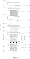
- FIG. 1 there is shown an apparatus for producing a printed panel in one embodiment of the present invention for performing a method according to the present invention.
- the device comprises a feed device 10 for feeding a plate-shaped carrier 12, so that the carrier 12 runs in the direction of arrow 14 as the direction of travel. Downstream of the feed device 12 is an application unit 16 for applying a resin layer 18 to the fed carrier 12. In the direction of travel behind the application unit 16 there is a feed device 20 for applying a paper or fleece layer 22 to the plate-shaped carrier 12. What is not shown is an adjoining unit for calendering, in particular with heat, of a layer structure comprising the carrier, the resin layer 18 and the paper or non-woven layer 22.
- FIG Figure 1 Furthermore, an application unit 24 is provided for applying a printing substrate 26 to the carrier 12. In the direction of travel of the carrier 12 behind the application unit 24, printing of the carrier 12 can follow.
- a printing unit 28 is provided for printing the carrier 12 with an application quantity of radiation-curable printing ink 30.
- a radiation unit 32 is provided for treating the printed carrier 12 with radiation for curing the radiation-curable printing ink 30, so that the carrier 12 is provided with cured printing ink 44.
- FIG Figure 1 shown that the radiation unit 32 has five radiators 34, 36, 38, 40, 42. These can be arranged side by side, but can in principle, any arrangement of the radiators 34, 36, 38, 40, 42 can be covered by the present invention.
- the device has a control unit 46 which is connected, for example, to the printing unit 28 and the radiation unit 32 for data transmission with a data connection 48.
- the control unit 46 can be fed with data relating to an application amount of the radiation-curable printing ink 30 and can determine at least one parameter of radiation emitted by the radiation unit 32 on the basis of the application amount.
- the data relating to the application quantity can be generated by sensors (not shown) for determining the applied printing ink 30.
- the determination of the application amount of the radiation-curable printing ink can be carried out during the printing process using at least one optical sensor that detects an discharge area of a print head.
- the determination of the application quantity of the radiation-curable printing ink is carried out during the printing process using at least one optical sensor which detects the printed carrier.
- provision can also be made for the application quantity of the radiation-curable printing ink to be determined during the printing process using a flow sensor which detects an ink line upstream of a print head or within a print head.
- control unit 46 transmits the at least one parameter to the radiation unit 32.
- the radiation unit 32 in turn can use the printing ink 30 harden taking this parameter into account.
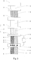
- FIG. 3 another example is shown.
- part of the printing ink 30 is applied to the carrier 12 with a comparatively small amount of radiation-curable printing ink 30 applied, and furthermore a part of the printing ink 30 is applied to the carrier 12 with a comparatively high amount of radiation-curable printing ink 30 applied.
- curing or irradiation of the printing ink 30 can take place locally differently by using the radiators 34, 36, 38 and 42. It can be seen that a wide variety of adjustments can also be possible with differently printed decor areas.
- the following parameter selection can be made, the application quantities relating to the entire decor.
- an application amount of ⁇ 2g / m 2 for example, one emitter can be used, with an application amount of ⁇ 2g / m 2 to ⁇ 5g / m 2 , for example, two emitters can be used, with an application amount of ⁇ 5g / m 2 to ⁇ 8g / m 2 , for example, three emitters can be used, with an application amount of 8g / m 2 to ⁇ 10g / m 2 , for example, four emitters can be used and with an application amount of ⁇ 10 g / m 2 , for example, five emitters can be used, the above values being understood as purely exemplary.
- a UV radiator with a given UV-curable ink with applied ink quantities of ⁇ 1 ml / m 2, with a dose of 280 mJ / cm 2 acting on the ink.
- two UV radiators arranged one behind the other are used, with a dose of 550 mJ / cm 2 acting on the ink, and that with applied amounts of ink > 5ml / m 2 is worked with three successively arranged UV lamps, a dose of 830 mJ / cm 2 acting on the ink.
- the feed rate of the panel is 25 m / min in all examples.
- a dwell time in the direct focus of the radiator which can have an area corresponding to the direction of movement of the carrier of approximately 10 mm, can be approximately 0.024 s, with the dwell time in an extended Focus, which can have a range corresponding to the direction of movement of the carrier of approximately 50 mm, of approximately 0.12 s.
- the dose in the wavelength range 230-410 nm was measured using a mercury emitter.
- the aforementioned parameters can differ in addition to the specific ink used, for example based on doping of the radiator.
- the dose can be determined, for example, by a product from UV-Technik Meyer GmbH sold under the name "UV-Micro-Puck”.
- the aforementioned adjustments are also dependent on the desired curing result, which is achieved by the influence of the emitters on the ink. Consequently
- the radiation used, which acts on the ink can be selected in particular against the background that the ink is optionally pressed together with a layer arranged on the ink, such as a melamine resin layer or lacquer layer, to introduce haptically perceptible structures.
- a stronger hardening or a stronger dose acting on the ink may be necessary than in the case of an ink layer which is not subjected to any compression.
Landscapes
- Physics & Mathematics (AREA)
- Health & Medical Sciences (AREA)
- Electromagnetism (AREA)
- General Health & Medical Sciences (AREA)
- Toxicology (AREA)
- Life Sciences & Earth Sciences (AREA)
- Engineering & Computer Science (AREA)
- Wood Science & Technology (AREA)
- Application Of Or Painting With Fluid Materials (AREA)
- Printing Methods (AREA)
- Laminated Bodies (AREA)
Claims (11)
- Procédé de fabrication d'un panneau imprimé, présentant les étapes de procédé :a) de mise au point d'un support (12) en forme de plaque ;b) éventuellement, d'application d'une couche de résine (18) sur le support (12) en forme de plaque ;c) éventuellement, d'application d'une couche de papier ou de non tissé (22) sur le support (12) en forme de plaque ;d) éventuellement, de calandrage de la structure en couches résultante, en particulier à une température entre ≥ 40 ° et ≤ 250 °C, ete) éventuellement, d'application d'un fond d'impression (26) sur le support (12) en forme de plaque ;f) d'impression du support (12) avec une quantité d'application de peinture d'impression (30) durcissable par rayonnement ; etg) du durcissement de la peinture d'impression (30) précédemment appliquée par le traitement de la peinture d'impression (30) avec un rayonnement, oùh) au moins un paramètre du rayonnement employé lors de l'étape de procédé g) est adapté à la quantité d'application de la peinture d'impression (30) durcissable par rayonnement, où l'étape de procédé h) se base sur une quantité d'application de la peinture d'impression (30) durcissable par rayonnement déterminée par un capteur durant le processus d'impression, où au moins un paramètre du rayonnement employé lors de l'étape de procédé g) est adapté pendant l'impression du support (12) selon l'étape de procédé f).
- Procédé selon la revendication 1, caractérisé en ce que l'évaluation de la quantité d'application de la peinture d'impression (30) durcissable par rayonnement est effectuée pendant le processus d'impression moyennant l'emploi d'au moins un capteur optique qui détecte une zone de décharge d'une tête d'impression.
- Procédé selon la revendication 1 ou la revendication 2, caractérisé en ce que l'évaluation de la quantité d'application de la peinture d'impression (30) durcissable par rayonnement est effectuée pendant le processus d'impression moyennant l'emploi d'au moins un capteur optique qui détecte le support (12) imprimé.
- Procédé selon l'une des revendications 1 à 3, caractérisé en ce que l'évaluation de la quantité d'application de la peinture d'impression (30) durcissable par rayonnement est effectuée pendant le processus d'impression moyennant l'emploi d'un débitmètre qui détecte sur une conduite de peinture en amont d'une tête d'impression ou à l'intérieur d'une tête d'impression.
- Procédé selon l'une des revendications 1 à 4, caractérisé en ce qu'un signal d'avertissement est indiqué lors d'une déviation de la quantité d'application par rapport à la quantité d'application souhaitée.
- Procédé selon l'une des revendications 1 à 5, caractérisé en ce qu'au moins un paramètre du rayonnement employé lors de l'étape g) est adapté dans une multiplicité de zones différentes localement les unes des autres de manière indépendante les unes des autres.
- Procédé selon l'une des revendications 1 à 6, caractérisé en ce que l'au moins un paramètre adapté du rayonnement employé lors de l'étape de procédé g) comprend le nombre de dispositifs de rayonnement (34, 36, 38, 40, 42).
- Procédé selon l'une des revendications 1 à 7, caractérisé en ce que l'au moins un paramètre adapté du rayonnement employé lors de l'étape de procédé g) comprend la puissance d'au moins un dispositif de rayonnement (34, 36, 38, 40, 42).
- Procédé selon l'une des revendications 1 à 8, caractérisé en ce que l'au moins un paramètre adapté du rayonnement employé lors de l'étape de procédé g) comprend la durée d'exposition au rayonnement de la peinture d'impression (30) durcissable par rayonnement.
- Procédé selon l'une des revendications 1 à 9, caractérisé en ce que l'étape de procédé f) est réalisée moyennant l'emploi d'un procédé d'impression numérique.
- Dispositif de fabrication d'un panneau imprimé, présentant- un dispositif d'approvisionnement (10) pour l'approvisionnement d'un support (12) en forme de plaque ;- éventuellement, une unité d'application (16) pour l'application d'une couche de résine (18) sur le support (12) en place ;- éventuellement, un dispositif d'approvisionnement (20) pour l'application d'une couche de papier ou de non tissé (22) sur le support (12) en forme de plaque ;- éventuellement, une unité pour le calandrage d'une structure en couches comprenant le support (12), la couche de résine (18) et la couche de papier ou de non tissé (22) ;- éventuellement, une unité d'application (24) pour l'application d'un fond d'impression (26) sur le support (12) ;- une unité d'impression (28) pour l'impression du support (12) avec une peinture d'impression (30) durcissable par rayonnement ; et- une unité de rayonnement (32) pour le traitement du support (12) imprimé avec un rayonnement pour le durcissement de la peinture d'impression (30) durcissable par rayonnement, où, en outre il est prévu :- au moins un capteur pour l'évaluation de la quantité d'application de la peinture d'impression durcissable par rayonnement ;- une unité de commande (46), laquelle peut être alimentée avec des données de l'au moins un capteur concernant une quantité d'application de la peinture d'impression (30) durcissable par rayonnement évaluée pendant le processus d'impression, où l'unité de commande évalue, sur la base de la quantité d'application, au moins un paramètre du rayonnement émis par l'unité de rayonnement (32), et laquelle est reliée avec l'unité de rayonnement (32) pour la transmission de l'au moins un paramètre par une liaison de données (48), et où l'exposition au rayonnement peut être effectuée par l'unité de rayonnement (32) sur la base de l'au moins un paramètre.
Applications Claiming Priority (2)
| Application Number | Priority Date | Filing Date | Title |
|---|---|---|---|
| EP16152633.0A EP3196046A1 (fr) | 2016-01-25 | 2016-01-25 | Procede de fabrication d'un panneau de decoration imprime |
| PCT/EP2017/051435 WO2017129566A1 (fr) | 2016-01-25 | 2017-01-24 | Procédé de fabrication d'un panneau décoratif imprimé |
Publications (2)
| Publication Number | Publication Date |
|---|---|
| EP3408108A1 EP3408108A1 (fr) | 2018-12-05 |
| EP3408108B1 true EP3408108B1 (fr) | 2020-11-25 |
Family
ID=55262702
Family Applications (2)
| Application Number | Title | Priority Date | Filing Date |
|---|---|---|---|
| EP16152633.0A Withdrawn EP3196046A1 (fr) | 2016-01-25 | 2016-01-25 | Procede de fabrication d'un panneau de decoration imprime |
| EP17701147.5A Active EP3408108B1 (fr) | 2016-01-25 | 2017-01-24 | Procede de fabrication d'un panneau de decoration imprime |
Family Applications Before (1)
| Application Number | Title | Priority Date | Filing Date |
|---|---|---|---|
| EP16152633.0A Withdrawn EP3196046A1 (fr) | 2016-01-25 | 2016-01-25 | Procede de fabrication d'un panneau de decoration imprime |
Country Status (5)
| Country | Link |
|---|---|
| US (1) | US10814669B2 (fr) |
| EP (2) | EP3196046A1 (fr) |
| CN (1) | CN108698435B (fr) |
| ES (1) | ES2848183T3 (fr) |
| WO (1) | WO2017129566A1 (fr) |
Cited By (1)
| Publication number | Priority date | Publication date | Assignee | Title |
|---|---|---|---|---|
| DE102023111757A1 (de) | 2023-05-05 | 2024-11-07 | Homag Gmbh | Verfahren zum Verarbeiten eines plattenförmigen Werkstücks |
Families Citing this family (6)
| Publication number | Priority date | Publication date | Assignee | Title |
|---|---|---|---|---|
| SI3245249T1 (sl) * | 2015-01-16 | 2020-02-28 | Beaulieu International Group Nv | Pokrivne plošče in postopek za izdelavo pokrivnih plošč |
| EP3516130B1 (fr) | 2016-09-23 | 2023-05-10 | Shaw Industries Group, Inc. | Produit de revêtement de sol élastique et procédés de fabrication de celui-ci |
| CN111469223A (zh) * | 2019-01-23 | 2020-07-31 | 山东卓远装饰材料有限公司 | 一种净醛除菌防污的家具板材及其制备工艺 |
| CN111516590B (zh) * | 2020-04-22 | 2021-11-05 | 北斗星通智联科技有限责任公司 | 一种车载播放器iml一体面板及其制备工艺 |
| IT202100025811A1 (it) * | 2021-10-08 | 2023-04-08 | Foliae S R L | Film decorativo particolarmente del tipo perfezionato. |
| DE102023112081A1 (de) * | 2023-05-09 | 2024-11-14 | Homag Gmbh | Verfahren zum Bedrucken eines Beschichtungsmaterials sowie System |
Family Cites Families (11)
| Publication number | Priority date | Publication date | Assignee | Title |
|---|---|---|---|---|
| US7140711B2 (en) * | 2003-07-21 | 2006-11-28 | 3M Innovative Properties Company | Method and apparatus for inkjet printing using radiation curable ink |
| US7789503B2 (en) * | 2005-08-17 | 2010-09-07 | Fujifilm Corporation | Image forming apparatus and image forming method |
| JP2008080728A (ja) * | 2006-09-28 | 2008-04-10 | Fujifilm Corp | インク吐出量測定方法及びインク吐出量測定システム |
| JP4697197B2 (ja) * | 2006-10-30 | 2011-06-08 | セイコーエプソン株式会社 | インクジェット記録方法 |
| JP5078529B2 (ja) * | 2007-09-28 | 2012-11-21 | キヤノン株式会社 | インクジェット記録ヘッドおよびそれを備えるインクジェット記録装置 |
| JP5328296B2 (ja) * | 2007-11-30 | 2013-10-30 | キヤノン株式会社 | インクジェット記録ヘッドおよびインクジェット記録装置 |
| US8795422B2 (en) * | 2009-08-31 | 2014-08-05 | Hewlett-Packard Development Company, L.P. | Naphthalocyanine dye and ink containing the same |
| JP5682752B2 (ja) * | 2011-01-11 | 2015-03-11 | セイコーエプソン株式会社 | 記録装置 |
| AU2013369538B2 (en) | 2012-12-28 | 2016-02-11 | Surface Technologies Gmbh & Co. Kg | Method for producing a printing material and a directly printed decorative panel |
| EP2829416A1 (fr) * | 2013-07-24 | 2015-01-28 | Surface Technologies GmbH & Co. KG | Procédé de fabrication d'un panneau de décoration directement imprimé sans couche de contre-traction |
| EP3323628B1 (fr) | 2014-02-25 | 2022-06-15 | Akzenta Paneele + Profile GmbH | Procédé de fabrication de panneaux décoratifs |
-
2016
- 2016-01-25 EP EP16152633.0A patent/EP3196046A1/fr not_active Withdrawn
-
2017
- 2017-01-24 US US16/072,035 patent/US10814669B2/en active Active
- 2017-01-24 CN CN201780012546.0A patent/CN108698435B/zh active Active
- 2017-01-24 ES ES17701147T patent/ES2848183T3/es active Active
- 2017-01-24 EP EP17701147.5A patent/EP3408108B1/fr active Active
- 2017-01-24 WO PCT/EP2017/051435 patent/WO2017129566A1/fr not_active Ceased
Non-Patent Citations (1)
| Title |
|---|
| None * |
Cited By (1)
| Publication number | Priority date | Publication date | Assignee | Title |
|---|---|---|---|---|
| DE102023111757A1 (de) | 2023-05-05 | 2024-11-07 | Homag Gmbh | Verfahren zum Verarbeiten eines plattenförmigen Werkstücks |
Also Published As
| Publication number | Publication date |
|---|---|
| EP3196046A1 (fr) | 2017-07-26 |
| CN108698435A (zh) | 2018-10-23 |
| US10814669B2 (en) | 2020-10-27 |
| EP3408108A1 (fr) | 2018-12-05 |
| US20190023061A1 (en) | 2019-01-24 |
| CN108698435B (zh) | 2021-01-12 |
| ES2848183T3 (es) | 2021-08-05 |
| WO2017129566A1 (fr) | 2017-08-03 |
Similar Documents
| Publication | Publication Date | Title |
|---|---|---|
| EP2938494B1 (fr) | Procédé destiné à la fabrication d'un substrat d'impression et substrat d'impression ainsi obtenu | |
| EP3109056B2 (fr) | Procede et dispositif de fabrication d'une structure sur une surface | |
| EP3403846B1 (fr) | Procédé de fabrication d'un panneau mural ou de sol décoré | |
| EP3323628B1 (fr) | Procédé de fabrication de panneaux décoratifs | |
| EP3408108A1 (fr) | Procédé de fabrication d'un panneau décoratif imprimé | |
| EP3532300B1 (fr) | Procédé de fabrication d'un panneau mural ou de sol décoré | |
| WO2008061765A1 (fr) | Procédé d'impression directe de plaques en matériau à base de bois | |
| EP2829415A1 (fr) | Procédé de fabrication d'un panneau mural et de sol décoré | |
| EP2730429A1 (fr) | Procédé de fabrication d'un panneau mural ou de sol décoré | |
| EP3253588B1 (fr) | Procédé de fabrication d'un support d'impression ainsi qu'un panneau décoratif à impression directe | |
| EP3132945B1 (fr) | Procede de fabrication d'un panneau mural ou de sol decore | |
| EP3999293B1 (fr) | Panneaux à surface de peinture structurée | |
| EP2749413B1 (fr) | Procédé destiné à la fabrication d'un substrat d'impression | |
| EP3088204B1 (fr) | Procédé de fabrication d'un panneau mural ou de sol décoré | |
| EP3632700A1 (fr) | Feuille de protection contre l'usure structurée par impression numérique | |
| EP2829416A1 (fr) | Procédé de fabrication d'un panneau de décoration directement imprimé sans couche de contre-traction | |
| EP3088205A1 (fr) | Procédé de fabrication d'un panneau mural ou de sol décoré |
Legal Events
| Date | Code | Title | Description |
|---|---|---|---|
| STAA | Information on the status of an ep patent application or granted ep patent |
Free format text: STATUS: UNKNOWN |
|
| STAA | Information on the status of an ep patent application or granted ep patent |
Free format text: STATUS: THE INTERNATIONAL PUBLICATION HAS BEEN MADE |
|
| PUAI | Public reference made under article 153(3) epc to a published international application that has entered the european phase |
Free format text: ORIGINAL CODE: 0009012 |
|
| STAA | Information on the status of an ep patent application or granted ep patent |
Free format text: STATUS: REQUEST FOR EXAMINATION WAS MADE |
|
| 17P | Request for examination filed |
Effective date: 20180606 |
|
| AK | Designated contracting states |
Kind code of ref document: A1 Designated state(s): AL AT BE BG CH CY CZ DE DK EE ES FI FR GB GR HR HU IE IS IT LI LT LU LV MC MK MT NL NO PL PT RO RS SE SI SK SM TR |
|
| AX | Request for extension of the european patent |
Extension state: BA ME |
|
| DAV | Request for validation of the european patent (deleted) | ||
| DAX | Request for extension of the european patent (deleted) | ||
| GRAP | Despatch of communication of intention to grant a patent |
Free format text: ORIGINAL CODE: EPIDOSNIGR1 |
|
| STAA | Information on the status of an ep patent application or granted ep patent |
Free format text: STATUS: GRANT OF PATENT IS INTENDED |
|
| INTG | Intention to grant announced |
Effective date: 20200722 |
|
| GRAS | Grant fee paid |
Free format text: ORIGINAL CODE: EPIDOSNIGR3 |
|
| GRAA | (expected) grant |
Free format text: ORIGINAL CODE: 0009210 |
|
| STAA | Information on the status of an ep patent application or granted ep patent |
Free format text: STATUS: THE PATENT HAS BEEN GRANTED |
|
| AK | Designated contracting states |
Kind code of ref document: B1 Designated state(s): AL AT BE BG CH CY CZ DE DK EE ES FI FR GB GR HR HU IE IS IT LI LT LU LV MC MK MT NL NO PL PT RO RS SE SI SK SM TR |
|
| REG | Reference to a national code |
Ref country code: GB Ref legal event code: FG4D Free format text: NOT ENGLISH |
|
| REG | Reference to a national code |
Ref country code: CH Ref legal event code: EP |
|
| REG | Reference to a national code |
Ref country code: AT Ref legal event code: REF Ref document number: 1337860 Country of ref document: AT Kind code of ref document: T Effective date: 20201215 |
|
| REG | Reference to a national code |
Ref country code: DE Ref legal event code: R096 Ref document number: 502017008352 Country of ref document: DE |
|
| REG | Reference to a national code |
Ref country code: IE Ref legal event code: FG4D Free format text: LANGUAGE OF EP DOCUMENT: GERMAN |
|
| REG | Reference to a national code |
Ref country code: NL Ref legal event code: MP Effective date: 20201125 |
|
| PG25 | Lapsed in a contracting state [announced via postgrant information from national office to epo] |
Ref country code: RS Free format text: LAPSE BECAUSE OF FAILURE TO SUBMIT A TRANSLATION OF THE DESCRIPTION OR TO PAY THE FEE WITHIN THE PRESCRIBED TIME-LIMIT Effective date: 20201125 Ref country code: PT Free format text: LAPSE BECAUSE OF FAILURE TO SUBMIT A TRANSLATION OF THE DESCRIPTION OR TO PAY THE FEE WITHIN THE PRESCRIBED TIME-LIMIT Effective date: 20210325 Ref country code: NO Free format text: LAPSE BECAUSE OF FAILURE TO SUBMIT A TRANSLATION OF THE DESCRIPTION OR TO PAY THE FEE WITHIN THE PRESCRIBED TIME-LIMIT Effective date: 20210225 Ref country code: GR Free format text: LAPSE BECAUSE OF FAILURE TO SUBMIT A TRANSLATION OF THE DESCRIPTION OR TO PAY THE FEE WITHIN THE PRESCRIBED TIME-LIMIT Effective date: 20210226 Ref country code: FI Free format text: LAPSE BECAUSE OF FAILURE TO SUBMIT A TRANSLATION OF THE DESCRIPTION OR TO PAY THE FEE WITHIN THE PRESCRIBED TIME-LIMIT Effective date: 20201125 |
|
| PG25 | Lapsed in a contracting state [announced via postgrant information from national office to epo] |
Ref country code: SE Free format text: LAPSE BECAUSE OF FAILURE TO SUBMIT A TRANSLATION OF THE DESCRIPTION OR TO PAY THE FEE WITHIN THE PRESCRIBED TIME-LIMIT Effective date: 20201125 Ref country code: BG Free format text: LAPSE BECAUSE OF FAILURE TO SUBMIT A TRANSLATION OF THE DESCRIPTION OR TO PAY THE FEE WITHIN THE PRESCRIBED TIME-LIMIT Effective date: 20210225 Ref country code: LV Free format text: LAPSE BECAUSE OF FAILURE TO SUBMIT A TRANSLATION OF THE DESCRIPTION OR TO PAY THE FEE WITHIN THE PRESCRIBED TIME-LIMIT Effective date: 20201125 Ref country code: IS Free format text: LAPSE BECAUSE OF FAILURE TO SUBMIT A TRANSLATION OF THE DESCRIPTION OR TO PAY THE FEE WITHIN THE PRESCRIBED TIME-LIMIT Effective date: 20210325 Ref country code: PL Free format text: LAPSE BECAUSE OF FAILURE TO SUBMIT A TRANSLATION OF THE DESCRIPTION OR TO PAY THE FEE WITHIN THE PRESCRIBED TIME-LIMIT Effective date: 20201125 |
|
| REG | Reference to a national code |
Ref country code: LT Ref legal event code: MG9D |
|
| PG25 | Lapsed in a contracting state [announced via postgrant information from national office to epo] |
Ref country code: HR Free format text: LAPSE BECAUSE OF FAILURE TO SUBMIT A TRANSLATION OF THE DESCRIPTION OR TO PAY THE FEE WITHIN THE PRESCRIBED TIME-LIMIT Effective date: 20201125 |
|
| PG25 | Lapsed in a contracting state [announced via postgrant information from national office to epo] |
Ref country code: RO Free format text: LAPSE BECAUSE OF FAILURE TO SUBMIT A TRANSLATION OF THE DESCRIPTION OR TO PAY THE FEE WITHIN THE PRESCRIBED TIME-LIMIT Effective date: 20201125 Ref country code: SK Free format text: LAPSE BECAUSE OF FAILURE TO SUBMIT A TRANSLATION OF THE DESCRIPTION OR TO PAY THE FEE WITHIN THE PRESCRIBED TIME-LIMIT Effective date: 20201125 Ref country code: SM Free format text: LAPSE BECAUSE OF FAILURE TO SUBMIT A TRANSLATION OF THE DESCRIPTION OR TO PAY THE FEE WITHIN THE PRESCRIBED TIME-LIMIT Effective date: 20201125 Ref country code: EE Free format text: LAPSE BECAUSE OF FAILURE TO SUBMIT A TRANSLATION OF THE DESCRIPTION OR TO PAY THE FEE WITHIN THE PRESCRIBED TIME-LIMIT Effective date: 20201125 Ref country code: CZ Free format text: LAPSE BECAUSE OF FAILURE TO SUBMIT A TRANSLATION OF THE DESCRIPTION OR TO PAY THE FEE WITHIN THE PRESCRIBED TIME-LIMIT Effective date: 20201125 Ref country code: LT Free format text: LAPSE BECAUSE OF FAILURE TO SUBMIT A TRANSLATION OF THE DESCRIPTION OR TO PAY THE FEE WITHIN THE PRESCRIBED TIME-LIMIT Effective date: 20201125 |
|
| REG | Reference to a national code |
Ref country code: ES Ref legal event code: FG2A Ref document number: 2848183 Country of ref document: ES Kind code of ref document: T3 Effective date: 20210805 |
|
| REG | Reference to a national code |
Ref country code: DE Ref legal event code: R097 Ref document number: 502017008352 Country of ref document: DE |
|
| PG25 | Lapsed in a contracting state [announced via postgrant information from national office to epo] |
Ref country code: DK Free format text: LAPSE BECAUSE OF FAILURE TO SUBMIT A TRANSLATION OF THE DESCRIPTION OR TO PAY THE FEE WITHIN THE PRESCRIBED TIME-LIMIT Effective date: 20201125 Ref country code: MC Free format text: LAPSE BECAUSE OF FAILURE TO SUBMIT A TRANSLATION OF THE DESCRIPTION OR TO PAY THE FEE WITHIN THE PRESCRIBED TIME-LIMIT Effective date: 20201125 |
|
| REG | Reference to a national code |
Ref country code: CH Ref legal event code: PL |
|
| PG25 | Lapsed in a contracting state [announced via postgrant information from national office to epo] |
Ref country code: LU Free format text: LAPSE BECAUSE OF NON-PAYMENT OF DUE FEES Effective date: 20210124 |
|
| PLBE | No opposition filed within time limit |
Free format text: ORIGINAL CODE: 0009261 |
|
| STAA | Information on the status of an ep patent application or granted ep patent |
Free format text: STATUS: NO OPPOSITION FILED WITHIN TIME LIMIT |
|
| REG | Reference to a national code |
Ref country code: BE Ref legal event code: MM Effective date: 20210131 |
|
| GBPC | Gb: european patent ceased through non-payment of renewal fee |
Effective date: 20210225 |
|
| PG25 | Lapsed in a contracting state [announced via postgrant information from national office to epo] |
Ref country code: IT Free format text: LAPSE BECAUSE OF FAILURE TO SUBMIT A TRANSLATION OF THE DESCRIPTION OR TO PAY THE FEE WITHIN THE PRESCRIBED TIME-LIMIT Effective date: 20201125 Ref country code: NL Free format text: LAPSE BECAUSE OF FAILURE TO SUBMIT A TRANSLATION OF THE DESCRIPTION OR TO PAY THE FEE WITHIN THE PRESCRIBED TIME-LIMIT Effective date: 20201125 Ref country code: AL Free format text: LAPSE BECAUSE OF FAILURE TO SUBMIT A TRANSLATION OF THE DESCRIPTION OR TO PAY THE FEE WITHIN THE PRESCRIBED TIME-LIMIT Effective date: 20201125 Ref country code: FR Free format text: LAPSE BECAUSE OF NON-PAYMENT OF DUE FEES Effective date: 20210125 |
|
| 26N | No opposition filed |
Effective date: 20210826 |
|
| PG25 | Lapsed in a contracting state [announced via postgrant information from national office to epo] |
Ref country code: SI Free format text: LAPSE BECAUSE OF FAILURE TO SUBMIT A TRANSLATION OF THE DESCRIPTION OR TO PAY THE FEE WITHIN THE PRESCRIBED TIME-LIMIT Effective date: 20201125 Ref country code: CH Free format text: LAPSE BECAUSE OF NON-PAYMENT OF DUE FEES Effective date: 20210131 Ref country code: LI Free format text: LAPSE BECAUSE OF NON-PAYMENT OF DUE FEES Effective date: 20210131 |
|
| PG25 | Lapsed in a contracting state [announced via postgrant information from national office to epo] |
Ref country code: GB Free format text: LAPSE BECAUSE OF NON-PAYMENT OF DUE FEES Effective date: 20210225 Ref country code: IE Free format text: LAPSE BECAUSE OF NON-PAYMENT OF DUE FEES Effective date: 20210124 |
|
| PG25 | Lapsed in a contracting state [announced via postgrant information from national office to epo] |
Ref country code: IS Free format text: LAPSE BECAUSE OF FAILURE TO SUBMIT A TRANSLATION OF THE DESCRIPTION OR TO PAY THE FEE WITHIN THE PRESCRIBED TIME-LIMIT Effective date: 20210325 |
|
| PG25 | Lapsed in a contracting state [announced via postgrant information from national office to epo] |
Ref country code: BE Free format text: LAPSE BECAUSE OF NON-PAYMENT OF DUE FEES Effective date: 20210131 |
|
| REG | Reference to a national code |
Ref country code: AT Ref legal event code: MM01 Ref document number: 1337860 Country of ref document: AT Kind code of ref document: T Effective date: 20220124 |
|
| PG25 | Lapsed in a contracting state [announced via postgrant information from national office to epo] |
Ref country code: AT Free format text: LAPSE BECAUSE OF NON-PAYMENT OF DUE FEES Effective date: 20220124 |
|
| PG25 | Lapsed in a contracting state [announced via postgrant information from national office to epo] |
Ref country code: CY Free format text: LAPSE BECAUSE OF FAILURE TO SUBMIT A TRANSLATION OF THE DESCRIPTION OR TO PAY THE FEE WITHIN THE PRESCRIBED TIME-LIMIT Effective date: 20201125 |
|
| P01 | Opt-out of the competence of the unified patent court (upc) registered |
Effective date: 20230526 |
|
| PG25 | Lapsed in a contracting state [announced via postgrant information from national office to epo] |
Ref country code: HU Free format text: LAPSE BECAUSE OF FAILURE TO SUBMIT A TRANSLATION OF THE DESCRIPTION OR TO PAY THE FEE WITHIN THE PRESCRIBED TIME-LIMIT; INVALID AB INITIO Effective date: 20170124 |
|
| PG25 | Lapsed in a contracting state [announced via postgrant information from national office to epo] |
Ref country code: MK Free format text: LAPSE BECAUSE OF FAILURE TO SUBMIT A TRANSLATION OF THE DESCRIPTION OR TO PAY THE FEE WITHIN THE PRESCRIBED TIME-LIMIT Effective date: 20201125 |
|
| PG25 | Lapsed in a contracting state [announced via postgrant information from national office to epo] |
Ref country code: TR Free format text: LAPSE BECAUSE OF FAILURE TO SUBMIT A TRANSLATION OF THE DESCRIPTION OR TO PAY THE FEE WITHIN THE PRESCRIBED TIME-LIMIT Effective date: 20201125 |
|
| PG25 | Lapsed in a contracting state [announced via postgrant information from national office to epo] |
Ref country code: MT Free format text: LAPSE BECAUSE OF FAILURE TO SUBMIT A TRANSLATION OF THE DESCRIPTION OR TO PAY THE FEE WITHIN THE PRESCRIBED TIME-LIMIT Effective date: 20201125 |
|
| PGFP | Annual fee paid to national office [announced via postgrant information from national office to epo] |
Ref country code: ES Payment date: 20260227 Year of fee payment: 10 |
|
| PGFP | Annual fee paid to national office [announced via postgrant information from national office to epo] |
Ref country code: DE Payment date: 20260128 Year of fee payment: 10 |