EP3532300B1 - Procédé de fabrication d'un panneau mural ou de sol décoré - Google Patents
Procédé de fabrication d'un panneau mural ou de sol décoré Download PDFInfo
- Publication number
- EP3532300B1 EP3532300B1 EP17787451.8A EP17787451A EP3532300B1 EP 3532300 B1 EP3532300 B1 EP 3532300B1 EP 17787451 A EP17787451 A EP 17787451A EP 3532300 B1 EP3532300 B1 EP 3532300B1
- Authority
- EP
- European Patent Office
- Prior art keywords
- radiator
- radiation
- layer
- covering layer
- carrier
- Prior art date
- Legal status (The legal status is an assumption and is not a legal conclusion. Google has not performed a legal analysis and makes no representation as to the accuracy of the status listed.)
- Active
Links
Images

Classifications
-
- B—PERFORMING OPERATIONS; TRANSPORTING
- B44—DECORATIVE ARTS
- B44C—PRODUCING DECORATIVE EFFECTS; MOSAICS; TARSIA WORK; PAPERHANGING
- B44C5/00—Processes for producing special ornamental bodies
- B44C5/04—Ornamental plaques, e.g. decorative panels, decorative veneers
-
- B—PERFORMING OPERATIONS; TRANSPORTING
- B32—LAYERED PRODUCTS
- B32B—LAYERED PRODUCTS, i.e. PRODUCTS BUILT-UP OF STRATA OF FLAT OR NON-FLAT, e.g. CELLULAR OR HONEYCOMB, FORM
- B32B38/00—Ancillary operations in connection with laminating processes
-
- B—PERFORMING OPERATIONS; TRANSPORTING
- B41—PRINTING; LINING MACHINES; TYPEWRITERS; STAMPS
- B41M—PRINTING, DUPLICATING, MARKING, OR COPYING PROCESSES; COLOUR PRINTING
- B41M7/00—After-treatment of prints, e.g. heating, irradiating, setting of the ink, protection of the printed stock
-
- B—PERFORMING OPERATIONS; TRANSPORTING
- B41—PRINTING; LINING MACHINES; TYPEWRITERS; STAMPS
- B41M—PRINTING, DUPLICATING, MARKING, OR COPYING PROCESSES; COLOUR PRINTING
- B41M7/00—After-treatment of prints, e.g. heating, irradiating, setting of the ink, protection of the printed stock
- B41M7/0027—After-treatment of prints, e.g. heating, irradiating, setting of the ink, protection of the printed stock using protective coatings or layers by lamination or by fusion of the coatings or layers
-
- B—PERFORMING OPERATIONS; TRANSPORTING
- B41—PRINTING; LINING MACHINES; TYPEWRITERS; STAMPS
- B41M—PRINTING, DUPLICATING, MARKING, OR COPYING PROCESSES; COLOUR PRINTING
- B41M7/00—After-treatment of prints, e.g. heating, irradiating, setting of the ink, protection of the printed stock
- B41M7/0081—After-treatment of prints, e.g. heating, irradiating, setting of the ink, protection of the printed stock using electromagnetic radiation or waves, e.g. ultraviolet radiation, electron beams
-
- B—PERFORMING OPERATIONS; TRANSPORTING
- B44—DECORATIVE ARTS
- B44C—PRODUCING DECORATIVE EFFECTS; MOSAICS; TARSIA WORK; PAPERHANGING
- B44C3/00—Processes, not specifically provided for elsewhere, for producing ornamental structures
- B44C3/02—Superimposing layers
- B44C3/025—Superimposing layers to produce ornamental relief structures
-
- B—PERFORMING OPERATIONS; TRANSPORTING
- B44—DECORATIVE ARTS
- B44C—PRODUCING DECORATIVE EFFECTS; MOSAICS; TARSIA WORK; PAPERHANGING
- B44C5/00—Processes for producing special ornamental bodies
- B44C5/04—Ornamental plaques, e.g. decorative panels, decorative veneers
- B44C5/0461—Ornamental plaques, e.g. decorative panels, decorative veneers used as wall coverings
Definitions
- the present invention relates to a method for producing a decorated wall or floor panel.
- Such decorated panels are known per se, although the term "wall panel” also includes panels suitable for ceiling cladding. They typically consist of a carrier or core made of a solid material, such as a wood-based panel, which is coated on at least one side with a decorative layer and a cover layer, as well as optionally with additional layers, such as a wear layer arranged between the decorative and cover layers.
- the decorative layer is typically a printed paper impregnated with an aminoplast resin.
- the cover layer and the other layers are also usually made of aminoplast resin.
- WO 2015/128255 A1 A method for producing a decorative panel is known.
- a lacquer-containing top layer is partially cured, forming a curing gradient, with the curing gradient extending along the thickness of the top layer.
- the top layer is then structured and finally cured. Partial and final curing can be carried out using different wavelengths.
- the method described above thus serves to form a decorated wall or floor panel.
- decorated wall or floor panel or “decorative panel” in the context of the invention refers in particular to wall, ceiling, door, or floor panels that feature a decoration applied to a carrier plate.
- Decorative panels are used in a variety of ways, both in the interior design of rooms and for the decorative cladding of buildings, for example, in trade fair construction.
- One of the most common applications for decorative panels is their use as floor coverings.
- the decorative panels often feature a decoration intended to replicate a natural material.
- simulated natural materials include wood species such as maple, oak, birch, cherry, ash, walnut, chestnut, wenge, and even exotic woods such as panga-panga, mahogany, bamboo, and bubinga.
- wood species such as maple, oak, birch, cherry, ash, walnut, chestnut, wenge, and even exotic woods such as panga-panga, mahogany, bamboo, and bubinga.
- natural materials such as stone or ceramic surfaces are often simulated.
- a "plate-shaped support” in the sense of the present invention can be a natural material, such as a wood material, a fiber material or a material comprising a plastic which is in the form of a plate and can serve in particular as the core or as the base layer of the panel to be produced.
- the plate-shaped carrier can already impart suitable stability to the panel or contribute to this.
- the plate-shaped carrier can already specify the shape and/or size of the panel to be produced.
- the plate-shaped carrier can also be provided as a large plate.
- a large plate within the meaning of the invention is in particular a carrier whose dimensions exceed the dimensions of the final decorative panels by several times and which is divided into a corresponding plurality of decorative panels during the production process, for example by sawing, laser cutting or water jet cutting.
- a substrate can be made from a natural material, a plastic, or a wood-plastic composite (WPC).
- WPC wood-plastic composite
- Layered structures made from several of the aforementioned materials can also be used, such as plasterboard or wood-plastic laminated panels.
- the carrier plate can be made of a thermoplastic, elastomer, or thermosetting plastic.
- Mineral plates such as natural and artificial stone plates, concrete plates, gypsum fiber plates, so-called WPC plates (made from a mixture of plastic and wood), as well as plates made from natural raw materials such as cork and wood can also be used as carriers according to the invention.
- Plates made from biomass as a natural material such as straw, corn stalks, bamboo, leaves, algae extracts, hemp, and oil palm fibers can also be used according to the invention.
- recycled materials made from the aforementioned materials can be used within the scope of the inventive method.
- the plates can be based on the natural material cellulose, such as paper or cardboard.
- Wood-based materials within the meaning of the invention include, in addition to solid wood materials, materials such as cross-laminated timber, glued laminated timber, block laminated timber, veneer plywood, laminated veneer lumber, veneer strip lumber, and bending plywood. Furthermore, wood-based materials within the meaning of the invention also include wood particle materials such as chipboard, extruded boards, oriented structural boards (OSB), and chipboard strips, as well as wood fiber materials such as wood fiber insulation boards (HFD), medium-hard and hard fiberboards (MB, HFH), and in particular medium-density fiberboards (MDF) and high-density fiberboards (HDF).
- wood fiber insulation boards HFD
- MB medium-hard and hard fiberboards
- MDF medium-density fiberboards
- HDF high-density fiberboards
- Modern wood-based materials such as wood-polymer materials (wood-plastic composites, WPC), sandwich panels made of a lightweight core material such as foam, rigid foam, or paper honeycomb and a wood layer applied thereto, as well as mineral-bonded chipboards, for example with cement, constitute wood-based materials within the meaning of the invention.
- Cork also represents a wood-based material within the meaning of the invention.
- fiber materials refers to materials such as paper and nonwovens based on plant, animal, mineral, or even artificial fibers, as well as cardboard.
- fiber materials made from plant fibers include paper and nonwovens made from cellulose fibers, as well as panels made from biomass such as straw, corn stalks, bamboo, leaves, algae extracts, hemp, cotton, or oil palm fibers.
- animal fiber materials include keratin-based materials such as wool or horsehair.
- mineral fiber materials include materials made from mineral wool or glass wool.
- the carrier can be a plastic-based carrier, i.e., comprise or consist of a plastic.
- thermoplastics are polyvinyl chloride, polyolefins (e.g., polyethylene (PE), polypropylene (PP), polyamides (PA), polyurethanes (PU), polystyrene (PS), acrylonitrile butadiene styrene (ABS), Polymethyl methacrylate (PMMA), polycarbonate (PC), polyethylene terephthalate (PET), polyetheretherketone (PEEK), or mixtures or copolymers thereof.
- the plastics may contain conventional fillers, such as calcium carbonate (chalk), aluminum oxide, silica gel, quartz powder, wood flour, and gypsum. They may also be colored in a conventional manner.
- the carrier material may contain a flame retardant.
- Thermoplastics offer the advantage that the products made from them can be easily recycled. Recycled materials from other sources can also be used. This provides another opportunity to reduce manufacturing costs.
- the carrier is a plastic-containing carrier comprising a carrier material with a plastic-containing matrix material, into which a solid material, in particular with a particle size of less than or equal to 600 ⁇ m, is embedded.
- the matrix material may comprise polypropylene, for example in the form of LDPE, wherein the polypropylene may comprise a mixture of a homopolymer and a copolymer.
- the homopolymer is present in a proportion of ⁇ 10 wt.% to ⁇ 40 wt.%, for example in a proportion of ⁇ 20 wt.% to ⁇ 30 wt.%, for example in a proportion of ⁇ 23 wt.% to ⁇ 28 wt.%, based on the polypropylene, and/or that the copolymer is present in a proportion of ⁇ 60 wt.% to ⁇ 90 wt.%, for example in a proportion of ⁇ 70 wt.% to ⁇ 80 wt.%, for example in a proportion of ⁇ 72 wt.% to ⁇ 76 wt.%, based on the polypropylene, in particular wherein the polypropylene consists of the homopolymer and the copolymer.
- the solid can be, for example, a wood material, such as wood flour, or another material, such as a component of the rice plant, such as the rice husk, the Rice stalks and rice husks, cellulose or a mineral material such as rock flour, chalk or other inorganic mineral materials. It may be particularly preferred if the solid is formed from talc, for example consists thereof. In principle, the solids can be in the form of chips, shavings, flour or fibers. With regard to the use of talc as a solid, it can be advantageous that high stability can be achieved, particularly in this embodiment. Furthermore, such a carrier material can enable improved moisture resistance, in particular with reduced moisture- or heat-induced swelling. In this case, talc is understood in a conventional manner to be a magnesium silicate hydrate which, for example, can have the chemical formula Mg 3 [Si 4 O 10 (OH) 2 ].
- the solid material is formed by talc to an extent of at least 50% by weight, based on the solid material, wherein the matrix material is present in an amount, based on the carrier material, of ⁇ 30% by weight to ⁇ 70% by weight, for example of ⁇ 35% by weight to ⁇ 42% by weight, and wherein the solid material, based on the carrier material, is present in an amount, based on the carrier material, of ⁇ 30% by weight to ⁇ 80% by weight, for example of ⁇ 65% by weight to ⁇ 73% by weight, and wherein the carrier material and the solid material together are present in an amount of ⁇ 95% by weight, based on the carrier material.
- such a carrier can be provided or formed as is known for decorative panels.
- the carrier can be provided from a granular starting material, which is pressed under pressure and temperature into a corresponding plate-shaped carrier, whereby this example is in no way limiting.
- the method according to method step b) comprises applying a decoration simulating a decorative template to at least a partial area of the plate-shaped carrier.
- a "decorative template" in the present context can be understood, in particular, as an original natural material or at least a surface of such a material that is to be imitated or recreated by the decoration.
- the decoration can be applied, for example, by applying a printed paper or an unprinted or partially printed paper, which is then printed. Alternatively, the decoration can be printed directly onto the carrier or a suitable printing substrate, as described below.
- a decorative substrate can first be applied to at least a portion of the carrier.
- a primer particularly for printing processes, can first be applied as a decorative substrate, for example in a thickness of ⁇ 10 ⁇ m to ⁇ 60 ⁇ m.
- the primer can be a liquid radiation-curing mixture based on a urethane or a urethane acrylate, optionally with one or more of a photoinitiator, a reactive diluent, a UV stabilizer, a rheological agent such as a thickener, a radical scavenger, a flow control agent, a defoamer or preservative, a pigment, and/or a dye.
- a primer it is possible to apply the decoration to a decorative paper that can be printed with a corresponding decoration.
- This can be provided, for example, by means of a resin layer previously applied to the carrier as a bonding agent.
- a resin can be applied to the paper as a printing substrate, which can contain at least one compound selected from the group consisting of melamine resin, formaldehyde resin, urea resin, phenolic resin, epoxy resin, unsaturated polyester resin, diallyl phthalate, or mixtures thereof.
- the primer can preferably be applied to the carrier plate by means of rubber rollers, a casting machine, or by spraying.
- the primer is preferably applied in an amount between ⁇ 1 g/m 2 and ⁇ 100 g/m 2 , preferably between ⁇ 10 g/m 2 and ⁇ 50 g/m 2 , in particular between ⁇ 20 g/m 2 and ⁇ 40 g/m 2 .
- irradiation with a radiation source of a suitable wavelength takes place.
- a primer can also be applied directly onto the carrier or onto the primer.
- a white-colored primer can be applied, which can contain white color pigments, for example.
- the primer can be applied in two layers. It can be particularly preferred for the primer to be radiation-curable, for example UV-curable.
- a first layer of primer can preferably be cured before the application of a further layer of primer and/or before the decoration is printed.
- the primer can comprise polyurethane, for example in the form of a polyurethane varnish, and can be provided with white pigments.
- the decoration or decorative layer can be applied by direct printing.
- direct printing in the sense of the invention can be understood as the application of a decoration directly onto the support of a panel or onto an unprinted fiber material layer applied to the support.
- direct printing in contrast to conventional methods, in which a previously printed decorative layer is applied to a support, in direct printing the decoration is printed directly during the panel production.
- Different printing techniques can be used, such as flexographic printing, offset printing or screen printing. According to the invention, however, digital printing techniques such as For example, inkjet processes or inkjet printing processes or laser printing processes are used.
- direct printing also includes the application of the decoration using printing techniques to a printable layer previously applied to the substrate.
- a printable layer can be formed, for example, by a liquid-applied and subsequently cured primer layer or a previously applied printable film, paper, or nonwoven layer.
- the three-dimensional decorative data are provided in electronic form or in digital form.
- the provided decorative data can be used directly without any further intermediate steps, making the process particularly cost-effective and easy to implement, especially in this embodiment.
- the use of digital printing processes makes it possible to execute each printing process individually, thus enabling a particularly wide range of applications and dynamic adaptation to the desired product.
- the decorative layer or decoration can be formed from a particularly radiation-curable paint and/or ink.
- a UV-curable paint or ink can be used.
- the decorative layers or the decoration can each be applied in a thickness in a range of ⁇ 5 ⁇ m to ⁇ 10 ⁇ m.
- the decorative layers can each be applied in a thickness in a range of 8 ⁇ m.
- a particularly template-identical impression of the decoration or the panel can be achieved through a particularly thin design of the decorative layers and thus extremely precise variability of the surface application or the coverage of a layer by the respectively applied decorative layer.
- a cover layer is applied to the decoration, wherein the cover layer comprises a radiation-curing compound.
- a protective or cover layer can be understood in particular as a layer that protects underlying layers from wear and which can also serve to accommodate a structure.
- a plurality of cover layers are provided on the decoration to protect it. The design of the cover layers is described in detail below.
- the top layer may comprise an acrylate-based lacquer.
- the top layer may comprise one or more acrylates, which may be modified, in particular, by polyurethane (PU), or acrylate/polyurethane systems may be used.
- PU polyurethane
- the top layer is applied as a lacquer, for example, as a radiation-curable or at least partially radiation-curable composition. for example based on an epoxy varnish or a urethane acrylate.
- Such coating systems in particular, can form a particularly scratch- and impact-resistant top layer, which can make the decorative panel to be produced particularly durable.
- the present invention in particular, makes it possible to provide such coating systems with a negative structuring, thus enabling a particularly high-quality structural impression while retaining the advantages of the coating layer.
- the cover layer can, for example, have a layer thickness between ⁇ 100 ⁇ m and ⁇ 5mm, preferably between ⁇ 0.5mm and ⁇ 2.5 ⁇ m.
- a lower protective layer can have a structure and the upper protective layer can cover the lower protective layer.
- the lower layer has a comparatively higher viscosity when applied in order to be able to keep structures stable even before hardening, and/or that the upper layer has a comparatively low viscosity in order to be able to form a uniform finish.
- the lower layer has a greater thickness than the upper layer.
- the lower layer which can serve as a structural coating
- the upper layer which can serve as a topcoat
- the upper layer which can serve as a topcoat
- the cover layer contains hard materials such as titanium nitride, titanium carbide, silicon nitride, silicon carbide, boron carbide, tungsten carbide, tantalum carbide, aluminum oxide (corundum), zirconium oxide or mixtures thereof in order to To increase the wear resistance of the layer.
- the hard material is contained in the wear layer composition in an amount between 5 wt.% and 40 wt.%, preferably between 15 wt.% and 25 wt.%.
- the hard material preferably has an average grain diameter between 10 ⁇ m and 250 ⁇ m, more preferably between 10 ⁇ m and 100 ⁇ m. This advantageously ensures that the top layer composition forms a stable dispersion and demixing or settling of the hard material in the wear layer composition can be avoided.
- one embodiment may provide for the radiation-curable composition containing hard material to be applied in a concentration of between 10 g/m 2 and 250 g/m 2 , preferably between 25 g/m 2 and 100 g/m 2 .
- the application may be carried out, for example, by means of rollers, such as rubber rollers, or by means of casting devices.
- the hard material is not contained in the composition at the time of application of the top layer composition, but is scattered as particles onto the applied top layer composition and this is subsequently hardened by radiation.
- a structure in general, can be introduced into the cover layer by introducing pores, which is also referred to as synchronous pores.
- This can be achieved, for example, through so-called negative structuring, in which the cover layer is provided with a structure using an embossing tool, such as an embossing stamp or an embossing roller, by pressing the structure into the cover layer.
- the cover layer can first be partially cured, then provided with a structure, and then finally cured.
- the structure can also be introduced through so-called positive structuring, in which the structures are built up by applying a lacquer layer, particularly by selectively applying the raised areas of the structure. This is often achieved using negatively structured embossing media, which can apply the lacquer layer accordingly.
- positive structuring is achieved by printing a structure, for example, by optionally applying a multi-layer coating.
- Process step c) is carried out at least partially by a digital printing process.
- a structure can be applied in a particularly advantageous manner.
- a structure By printing a structure, it can be applied with the utmost precision and, particularly advantageously, as a synchronous pore in accordance with the decoration.
- appropriate three-dimensional decoration data can be used, for example, to print the decoration in order to achieve a visual appearance with a corresponding tactile structure that is as identical as possible or almost identical to a decoration template.
- Printing can be carried out using an inkjet printer or a laser printer, for example.
- the structure is not printed directly onto the decoration, but at least one, for example two, further layers of the cover layer or protective layer are arranged below the structure layer.
- This layer or layers can be applied in a conventional manner, for example, by roller application or similar. It may be possible to cure the individual layers beneath the structure, for example, using two emitters, as described in detail with its configurations, before the structure is printed. For example, a first layer of an abrasion-resistant layer can be applied, this can be cured, and a further abrasion-resistant layer can be applied and cured before the structure is printed.
- the abrasion-resistant layers or cover layers can be provided with abrasion-resistant particles as described above.
- the top layer and thus individual, several or all layers of the top layer, are provided with abrasion-resistant particles.
- a primer can be applied to the decor.
- a UV-curable primer can be applied.
- a UV-curing coating system such as an acrylate-based coating system, can be used as the primer.
- the printed structure of the cover layer can also be cured using multiple beam units. Curing with different wavelengths in a single curing step can be particularly advantageous, as it allows for particularly fast and effective curing, which can be beneficial with regard to the stability of the printed structure and thus the long-term stability and abrasion resistance of the produced panel.
- the structure can be printed using multiple layers, with each layer being cured before the application of a subsequent layer.
- a finishing layer is applied to the printed structure.
- This layer can, in turn, be formed by a varnish, such as an acrylic varnish, which can be applied using conventional methods.
- a varnish such as an acrylic varnish
- This final layer can further improve the stability of the layered structure and also enhance the appearance of the structure.
- all layers above the decoration are UV-curable and are cured before the application of a further layer, in particular using a plurality of emitters or a plurality of wavelengths, as described in detail elsewhere.
- all of these layers can be cured in one curing step, i.e., in a continuous curing step using different wavelengths.
- individual or all of the layers can contain abrasion-resistant particles.
- a surface texture that matches the decorative image means that the surface of the decorative panel has a tactile structure whose shape and pattern correspond to the appearance of the applied decoration, thus achieving the most faithful reproduction of a natural material, including its haptics.
- first radiator and the second radiator are to be used in a common curing step is to be understood in the sense of the present invention in particular as meaning that during a curing process, i.e. when the corresponding layer such as the cover layer is partially cured and/or When the top layer is finally cured, two emitters with different wavelengths are used. In other words, it can be provided that in one, several, or all curing processes, the top layer is cured using two emitters with different wavelengths.
- a curing step takes place using a radiation arrangement which has a first radiator and which has a second radiator, wherein the first radiator and the second radiator are designed to emit radiation with a different wavelength.
- the radiation arrangement is designed in particular to irradiate the cover layer by the first radiator and by the second radiator simultaneously, at least partially at the same position or at least partially at different, but adjacent positions.
- the cover layer is thus treated by the first radiator and the second radiator without further intermediate steps and thus in a common curing step by a common curing arrangement or radiation arrangement with two radiators.
- the curing behavior of the top layer can be significantly improved. Specifically, such a curing process with at least two different wavelengths in a common curing step can enable improved curing. This can potentially shorten the exposure time to the radiation, which can optimize process times.
- improved curing can increase the stability of the top layer, minimizing damage during transport or use. This can also allow structures incorporated into the top layer to remain intact even under high stress, which can improve the visual appearance even after intensive use.
- radiation with different wavelengths can be understood in particular as a first radiation and a second radiation, each having radiation maxima at at least one different position.
- patterns of radiation maxima can be present that differ completely or at least partially based on position, wavelength, and/or, if applicable, intensity.
- the first radiator emits radiation with radiation maxima in a wavelength range from greater than or equal to 395 nm to less than or equal to 445 nm.
- the second radiator emits radiation with radiation maxima in a wavelength range from greater than or equal to 200 nm to less than or equal to 440 nm.
- both radiators emit radiation with radiation maxima in a wavelength range from greater than or equal to 200 nm to less than or equal to 445 nm. It has surprisingly been found that in particular the use of one of the two aforementioned radiators, or particularly preferably a combination of the aforementioned emitters, which can improve the advantages with regard to process control and the stability of the product obtained.
- the first emitter may be a gallium emitter and the second emitter a mercury emitter.
- a combination of a gallium emitter and a mercury emitter may allow the aforementioned wavelength ranges to be maintained, thus realizing the advantages in terms of process control and the stability of the resulting product.
- the radiation intensity of the first radiator is in a ratio of greater than or equal to 0.5/1 to less than or equal to 1/0.5 to the radiation intensity of the second radiator. This enables a substantially uniform radiation intensity of the two radiators, which can further improve the curing result. It may preferably be provided that the radiation intensity of the first radiator is in a ratio of greater than or equal to 0.75/1 to less than or equal to 1/0.75 to the radiation intensity of the second radiator, for example in a ratio of greater than or equal to 0.9/1 to less than or equal to 1/0.9.
- the exposure time for example at a travel speed of the carrier during hardening of 25-35 m/s, is within a period of approximately one second, so that, depending on a fundamentally variable radiation focus, an exposure time of the total radiation to a position of less than 1 second may be sufficient.
- the first radiator and the second radiator are aligned in such a way that the radiation of the first radiator and the radiation of the second radiator simultaneously fall at least partially on different positions of the cover layer, the cover layer is thus initially separated from the first radiator and in particular immediately thereafter, i.e. without further intermediate steps, by the second radiator.
- the first radiator and the second radiator are aligned such that the radiation of the first radiator and the radiation of the second radiator simultaneously and completely fall on different positions of the cover layer, or that the first radiator and the second radiator are aligned such that the radiation of the first radiator and the radiation of the second radiator simultaneously partially fall on different positions of the cover layer and partially fall on an identical position of the cover layer, for example through scattering of the radiation.
- the cover layer can thus first be cured by radiation of one wavelength and in particular immediately thereafter by radiation of a further wavelength. It has surprisingly been shown that this embodiment can also allow advantages with regard to curing.
- the treatment with different wavelengths can be more specific with regard to the respective wavelength, which can make the curing more adaptable with regard to the respective field of application, i.e. for example with regard to the specific composition of the cover layer.
- the cover layer is first treated with radiation having radiation maxima in a wavelength range from greater than or equal to 395 nm to less than or equal to 445 nm and then with radiation having radiation maxima in a wavelength range from greater than or equal to 200 nm to less than or equal to 440 nm.
- the cover layer can first be treated with a gallium radiator and then with a mercury radiator. It has surprisingly been found that, in particular, this embodiment allows for particularly preferential curing.
- the first radiator and the second radiator may be aligned in such a way that the radiation from the first radiator and the radiation from the second radiator simultaneously fall at least partially onto an identical position of the cover layer.
- the cover layer is treated at least partially simultaneously by the first emitter and the second emitter, or by the corresponding radiation from the first emitter and the second emitter.
- the radiation from the first emitter and the second emitter can fall entirely on the same area of the cover layer at the same time.
- curing can be achieved particularly quickly, which can enable short process times and thus cost-effective production.
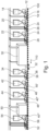
- FIG. 1 a method for producing a decorated wall or floor panel 10 is shown schematically.
- a conveyor device 100 is shown, on which an intermediate product comprising a carrier 12 is conveyed in the direction of arrow 110.
- the carrier 12 can be provided in a manner known per se and can generally be formed from a suitable material.
- a primer 16 is applied to the carrier 12 by an application device 14.
- the primer 16 can be UV-curable and cured by the blasting unit 18.
- a two-layer adhesive white base 24 can be applied by the application devices 20, 22.
- the Adhesive white primer 24 may in turn be UV-curable and cured by the blasting unit 26, 28, particularly after the application of each layer.
- the primer 16 or the adhesive white base 24 serves as the printing substrate.
- the carrier 12 is printed, forming a decoration 32.
- a further application unit 34 can apply a primer 36, in particular a UV-curable primer, and cure it by the blasting unit 38.
- the primer 36 serves as the base for a cover layer 40.
- the cover layer 40 can comprise a plurality of layers 40', 40", in particular comprising a radiation-curing lacquer, which can be applied by application devices 42, 44 and, after application, can be cured by blasting units 46, 48.
- the cover layer 40 comprises a further layer 40′′′, which has a structure, in particular in the sense of a synchronous pore.
- a further digital printing unit 50 is provided, which prints the layer 40′′′ in the sense of positive structuring in order to create a defined structure.
- the layer 40′′′ can then be cured directly by the blasting unit 52, or a final layer 56 can be applied by the application unit 54, followed by curing.
- each embodiment of the radiation unit 52 is shown, whereby the statements made here can generally apply to each of the described radiation units 16, 26, 28, 38, 46, 48. Particularly preferably, the embodiments shown can be used for the radiation units 18, 26, and 28 in addition to the radiation unit 52.
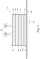
- the radiation unit 52 has a first radiator 58 and a second radiator 60, wherein the first radiator 58 emits radiation with a different wavelength than the radiation of the second radiator 60.
- the first radiator 58 is a gallium radiator and the second radiator 60 is a mercury radiator.
- the respective radiation unit 16, 26, 28, 38, 46, 48, 52 can be provided to harden the corresponding layer to be hardened during a hardening process with different wavelengths.
- first radiator 58 and the second radiator 60 are aligned such that the radiation of the first radiator 58 and the radiation of the second radiator 60 simultaneously fall at least partially onto an identical position of the cover layer 40.
- a preferred embodiment is in Figure 3 shown, according to which the first radiator 58 and the second radiator 60 are aligned such that the radiation of the first radiator 58 and the radiation of the second radiator 60 simultaneously fall at least partially on different but adjacent, i.e. in particular juxtaposed, positions of the cover layer 40.
Landscapes
- Physics & Mathematics (AREA)
- Health & Medical Sciences (AREA)
- Electromagnetism (AREA)
- General Health & Medical Sciences (AREA)
- Toxicology (AREA)
- Laminated Bodies (AREA)
- Finishing Walls (AREA)
- Application Of Or Painting With Fluid Materials (AREA)
Claims (13)
- Procédé de fabrication d'un panneau mural ou de sol décoré (10), comprenant les étapes suivantes:a) la fourniture d'un support en forme de plaque (12),b) l'application d'une décoration (32) reproduisant un modèle décoratif sur au moins une partie du support en forme de plaque (12),c) l'application d'une couche de revêtement (40) sur la décoration (32), dans lequel une telle couche de revêtement (40) comprenant un composé durcissant par rayonnement,d) le durcissement de la couche de revêtement (40), dans lequel une telle étape étant réalisée b) par un procédé d'impression numérique, et c) au moins partiellement par un procédé d'impression numérique et dans laquelle, pour former la couche de revêtement (40), au moins une première couche (40') est initialement appliquée sur la décoration (32), puis une couche (40") avec une structure est appliquée par un dispositif d'impression numérique (50), sur laquelle une couche finale (56) est appliquée au moyen d'une unité d'application (54), puis le durcissement est effectué conformément à l'étape d), caractérisée en ce que, dans l'étape d),la couche de revêtement (40) est durcie à l'aide d'un premier radiateur (58) et d'un deuxième radiateur (60), le premier radiateur (58) émettant un rayonnement dont la longueur d'onde est différente de celle du deuxième radiateur (60), et le premier radiateur (58) et le deuxième radiateur (60) étant utilisés durant une étape de durcissement commune sans étapes intermédiaires supplémentaires.
- Procédé selon la revendication 1, caractérisée en ce que le premier radiateur (58) émet un rayonnement avec des maxima de rayonnement dans une gamme de longueurs d'onde supérieure ou égale à 395 nm à inférieure ou égale à 445 nm.
- Procédé selon la revendication 1 ou 2, caractérisée en ce que le deuxième radiateur (60) émet un rayonnement avec des maxima de rayonnement dans une gamme de longueurs d'onde supérieure ou égale à 200 nm à inférieure ou égale à 440 nm.
- Procédé selon l'une des revendications 2 ou 3, caractérisée en ce que le premier radiateur (58) est un radiateur au gallium et le deuxième radiateur (60) est un radiateur au mercure.
- Procédé selon l'une des revendications précédentes, caractérisée en ce que l'intensité de rayonnement du premier radiateur (58) présente un rapport d'intensité de rayonnement par rapport au deuxième radiateur (60) supérieur ou égal à 0,5/1 à inférieur ou égal à 1/0,5.
- Procédé selon l'une des revendications précédentes, caractérisée en ce que le premier radiateur (58) et le deuxième radiateur (60) sont alignés de telle manière que le rayonnement du premier radiateur (58) et le rayonnement du deuxième radiateur (60) arrivent simultanément au moins partiellement sur des positions différentes de la couche de revêtement (40).
- Procédé selon la revendication 6, caractérisée en ce que la couche de revêtement (40) est d'abord traitée par un radiateur au gallium puis par un radiateur au mercure dans l'étape d).
- Procédé selon l'une des revendications précédentes, caractérisée en ce que le premier radiateur (58) et le deuxième radiateur (60) sont alignés de telle manière que le rayonnement du premier radiateur (58) et le rayonnement du deuxième radiateur (60) arrivent simultanément au moins partiellement sur une position identique de la couche de revêtement (40).
- Procédé selon l'une des revendications précédentes, caractérisée en ce qu'une laque durcissable par rayonnement est appliquée comme couche de revêtement (40).
- Procédé selon la revendication 9, caractérisée en ce que la laque durcissable par rayonnement est une laque acrylique.
- Procédé selon l'une des revendications précédentes, caractérisée en ce que la couche de revêtement (40) est dotée de particules résistantes à l'abrasion.
- Procédé selon l'une des revendications précédentes, caractérisée en ce que le support (12) comprend un matériau de matrice et un matériau solide réparti dans le matériau de matrice, le matériau solide étant formé d'au moins 50 % en poids, par rapport au matériau solide, de talc, le matériau de matrice étant présent en une quantité, par rapport au matériau de support, de ≥ 30 % en poids et ≤ 70 % en poids, et le matériau solide étant présent en une quantité de ≥ 30 % en poids et ≤ 70 % en poids par rapport au matériau de support, le matériau de matrice et le matériau solide étant présents ensemble en une quantité de ≥ 95 % en poids par rapport au matériau de support.
- Procédé selon la revendication 12, caractérisée en ce que le matériau de matrice comprend du polypropylène, le polypropylène comprenant un mélange d'un homopolymère et d'un copolymère.
Applications Claiming Priority (2)
| Application Number | Priority Date | Filing Date | Title |
|---|---|---|---|
| EP16196043.0A EP3315316B1 (fr) | 2016-10-27 | 2016-10-27 | Procédé de fabrication d'un panneau mural ou de sol décoré |
| PCT/EP2017/077504 WO2018078043A1 (fr) | 2016-10-27 | 2017-10-26 | Procédé de fabrication d'un panneau mural ou de sol décoré |
Publications (2)
| Publication Number | Publication Date |
|---|---|
| EP3532300A1 EP3532300A1 (fr) | 2019-09-04 |
| EP3532300B1 true EP3532300B1 (fr) | 2025-06-11 |
Family
ID=57209283
Family Applications (2)
| Application Number | Title | Priority Date | Filing Date |
|---|---|---|---|
| EP16196043.0A Active EP3315316B1 (fr) | 2016-10-27 | 2016-10-27 | Procédé de fabrication d'un panneau mural ou de sol décoré |
| EP17787451.8A Active EP3532300B1 (fr) | 2016-10-27 | 2017-10-26 | Procédé de fabrication d'un panneau mural ou de sol décoré |
Family Applications Before (1)
| Application Number | Title | Priority Date | Filing Date |
|---|---|---|---|
| EP16196043.0A Active EP3315316B1 (fr) | 2016-10-27 | 2016-10-27 | Procédé de fabrication d'un panneau mural ou de sol décoré |
Country Status (14)
| Country | Link |
|---|---|
| US (1) | US11065911B2 (fr) |
| EP (2) | EP3315316B1 (fr) |
| KR (1) | KR102226107B1 (fr) |
| CN (1) | CN109922971B (fr) |
| BR (1) | BR112019006973B1 (fr) |
| CA (1) | CA3038910C (fr) |
| CL (1) | CL2019001137A1 (fr) |
| ES (2) | ES2855111T3 (fr) |
| MX (1) | MX2019004908A (fr) |
| PL (2) | PL3315316T3 (fr) |
| PT (2) | PT3315316T (fr) |
| RU (1) | RU2721043C1 (fr) |
| UA (1) | UA122463C2 (fr) |
| WO (1) | WO2018078043A1 (fr) |
Families Citing this family (10)
| Publication number | Priority date | Publication date | Assignee | Title |
|---|---|---|---|---|
| ES2847940T3 (es) | 2015-09-24 | 2021-08-04 | Akzenta Paneele Profile Gmbh | Procedimiento para la fabricación de un panel de pared o de suelo decorado |
| ES2855111T3 (es) | 2016-10-27 | 2021-09-23 | Akzenta Paneele Profile Gmbh | Procedimiento para la fabricación de un panel de pared o de suelo decorado |
| EP3578384B1 (fr) | 2018-06-05 | 2021-10-20 | Akzenta Paneele + Profile GmbH | Matériau porteur à base d'une composition de matière plastique et d'une composition de matière solide minérales pour panneaux muraux ou de sol décorés |
| PL3632700T3 (pl) * | 2018-10-02 | 2021-12-20 | Akzenta Paneele + Profile Gmbh | Druk cyfrowy strukturalnej folii chroniącej przed zużyciem |
| EP3835027A1 (fr) | 2019-12-11 | 2021-06-16 | Akzenta Paneele + Profile GmbH | Procédé et dispositif de fabrication d'un panneau mural ou de sol décoré |
| DE102020109909A1 (de) | 2020-04-08 | 2021-10-14 | Leonhard Kurz Stiftung & Co. Kg | Verfahren zur Herstellung eines dekorierten, mineralischen Verbundkörpers, dekorierter, mineralischer Verbundkörper und Verwendung einer Mehrschichtfolie |
| EP3944845B1 (fr) * | 2020-07-30 | 2024-06-12 | The Procter & Gamble Company | Article absorbant comportant une zone de formation de canal et une couche de masquage |
| EP4188302B1 (fr) * | 2020-07-30 | 2026-01-07 | The Procter & Gamble Company | Article absorbant doté d'une couche intermédiaire inférieure partiellement liée à la partie centrale absorbante |
| CN216380385U (zh) * | 2021-02-06 | 2022-04-26 | 钟兵 | 一种安装方便的印制饰面人造石板材 |
| CN112918140A (zh) * | 2021-02-25 | 2021-06-08 | 刘超 | 一种用于智能制造的板材印花设备 |
Family Cites Families (33)
| Publication number | Priority date | Publication date | Assignee | Title |
|---|---|---|---|---|
| BE787311A (fr) * | 1971-08-09 | 1973-02-08 | Dart Ind Inc | Stratifie et son procede de realisation. |
| US4411931A (en) * | 1982-09-29 | 1983-10-25 | Armstrong World Industries, Inc. | Multiple step UV curing process for providing accurately controlled surface texture |
| DE19722339A1 (de) | 1997-05-28 | 1998-12-03 | Targor Gmbh | Schichtverbundmaterial mit kratzfester Oberfläche, Verfahren zu seiner Herstellung und seine Verwendung |
| KR100579841B1 (ko) * | 1998-12-08 | 2006-05-12 | 주식회사 엘지화학 | 멜라민 시트 적층 바닥 장식재 및 그 제조 방법 |
| US6096383A (en) * | 1999-04-28 | 2000-08-01 | Tennant Company | Curing of floor coatings using long and short wave ultraviolet radiation |
| SE516696C2 (sv) | 1999-12-23 | 2002-02-12 | Perstorp Flooring Ab | Förfarande för framställning av ytelement vilka innefattar ett övre dekorativt skikt samt ytelement framställda enlit förfarandet |
| JP4061014B2 (ja) * | 2000-09-28 | 2008-03-12 | 大日本印刷株式会社 | 化粧材 |
| US20030096096A1 (en) * | 2001-11-19 | 2003-05-22 | Jo Byeong H. | Plastic rail system reinforced with fiberglass thermoplastic composites |
| AU2003279701A1 (en) * | 2002-07-01 | 2004-01-19 | Inca Digital Printers Limited | Printing with ink |
| NO318008B1 (no) | 2002-11-14 | 2005-01-17 | Primefloor As | Fremgangsmåte og anordning for fremstilling av platelegemer av plastmateriale, samt anvendelse derav |
| EP1836232B2 (fr) | 2005-01-12 | 2016-08-03 | Borealis Technology Oy | Polyethylene de revetement par extrusion |
| US20070035601A1 (en) * | 2005-08-12 | 2007-02-15 | Jang James M | Cationic ink formulations |
| UA32517U (uk) | 2006-05-15 | 2008-05-26 | Ukrainian Academy Of Printin A | Пристрій для сушіння фотополімеризаційноздатних лаків ультрафіолетовим випромінюванням |
| CA2683707C (fr) | 2007-04-10 | 2016-03-08 | Spanolux N.V.- Div. Balterio | Procede et appareil de fabrication de panneaux de sol stratifies comprenant une ame contenant un composite polymere, ainsi que de tels panneaux |
| UA32585U (uk) | 2007-12-21 | 2008-05-26 | Андрей Анатольевич Пилипович | Спосіб виготовлення декорованих формованих виробів |
| WO2009152026A1 (fr) | 2008-06-10 | 2009-12-17 | Dow Global Technologies Inc. | Formation de motifs colorés de surface pendant l'étirage d'articles polymères |
| UA49197U (ru) | 2009-10-05 | 2010-04-26 | Владимир Витальевич Мирошниченко | Фасад для мебели |
| JP4818458B2 (ja) * | 2009-11-27 | 2011-11-16 | 株式会社Adeka | オキシムエステル化合物及び該化合物を含有する光重合開始剤 |
| CN201679200U (zh) * | 2010-02-25 | 2010-12-22 | 滁州扬子木业有限公司 | 亮面模压防水地板 |
| EP2444429B1 (fr) * | 2010-10-20 | 2016-09-07 | Agfa Graphics N.V. | Compositions durcissables de del |
| DE102011080300A1 (de) | 2011-08-02 | 2013-02-07 | Surface Technologies Gmbh & Co. Kg | Verfahren zur Herstellung einer dekorierten Wand-, Decken- oder Fußbodenplatte |
| ES2525102T3 (es) * | 2012-02-03 | 2014-12-17 | Agfa Graphics N.V. | Impresión por inyección de tinta de colores de madera |
| DE102012112556B4 (de) | 2012-12-18 | 2018-09-27 | Isimat Gmbh Siebdruckmaschinen | Verfahren und Vorrichtung zum Kaltprägen auf dreidimensionale Gegenstände |
| DE102013105728A1 (de) | 2013-06-04 | 2014-12-04 | POLIFILM EXTRUSION GmbH | Mehrschichtfolie mit thermisch aktivierbarer Kleberschicht |
| EP2829415A1 (fr) | 2013-07-22 | 2015-01-28 | Akzenta Paneele + Profile GmbH | Procédé de fabrication d'un panneau mural et de sol décoré |
| PL3323628T3 (pl) * | 2014-02-25 | 2022-10-10 | Akzenta Paneele + Profile Gmbh | Sposób wytwarzania paneli dekoracyjnych |
| CN106459626A (zh) * | 2014-04-15 | 2017-02-22 | 爱克发印艺公司 | 水性树脂基喷墨油墨 |
| EP2942208A1 (fr) | 2014-05-09 | 2015-11-11 | Akzenta Paneele + Profile GmbH | Procédé de fabrication d'un panneau mural ou de sol décoré |
| FI125896B (en) * | 2014-09-05 | 2016-03-31 | Upm Kymmene Corp | composite Material |
| RS56653B1 (sr) | 2014-12-08 | 2018-03-30 | Innovations4Flooring Holding N V | Panel sa zakačnim zabravnim sistemom |
| ES2847940T3 (es) * | 2015-09-24 | 2021-08-04 | Akzenta Paneele Profile Gmbh | Procedimiento para la fabricación de un panel de pared o de suelo decorado |
| ES2855111T3 (es) | 2016-10-27 | 2021-09-23 | Akzenta Paneele Profile Gmbh | Procedimiento para la fabricación de un panel de pared o de suelo decorado |
| EP3578384B1 (fr) | 2018-06-05 | 2021-10-20 | Akzenta Paneele + Profile GmbH | Matériau porteur à base d'une composition de matière plastique et d'une composition de matière solide minérales pour panneaux muraux ou de sol décorés |
-
2016
- 2016-10-27 ES ES16196043T patent/ES2855111T3/es active Active
- 2016-10-27 EP EP16196043.0A patent/EP3315316B1/fr active Active
- 2016-10-27 PT PT161960430T patent/PT3315316T/pt unknown
- 2016-10-27 PL PL16196043T patent/PL3315316T3/pl unknown
-
2017
- 2017-10-26 CA CA3038910A patent/CA3038910C/fr active Active
- 2017-10-26 ES ES17787451T patent/ES3037963T3/es active Active
- 2017-10-26 RU RU2019116022A patent/RU2721043C1/ru active
- 2017-10-26 UA UAA201905661A patent/UA122463C2/uk unknown
- 2017-10-26 MX MX2019004908A patent/MX2019004908A/es unknown
- 2017-10-26 BR BR112019006973-9A patent/BR112019006973B1/pt active IP Right Grant
- 2017-10-26 PT PT177874518T patent/PT3532300T/pt unknown
- 2017-10-26 KR KR1020197014856A patent/KR102226107B1/ko active Active
- 2017-10-26 EP EP17787451.8A patent/EP3532300B1/fr active Active
- 2017-10-26 WO PCT/EP2017/077504 patent/WO2018078043A1/fr not_active Ceased
- 2017-10-26 PL PL17787451.8T patent/PL3532300T3/pl unknown
- 2017-10-26 CN CN201780066858.XA patent/CN109922971B/zh active Active
- 2017-10-26 US US16/341,492 patent/US11065911B2/en active Active
-
2019
- 2019-04-25 CL CL2019001137A patent/CL2019001137A1/es unknown
Also Published As
| Publication number | Publication date |
|---|---|
| PL3315316T3 (pl) | 2021-06-14 |
| UA122463C2 (uk) | 2020-11-10 |
| US20190241009A1 (en) | 2019-08-08 |
| CN109922971B (zh) | 2021-08-17 |
| US11065911B2 (en) | 2021-07-20 |
| PT3532300T (pt) | 2025-08-20 |
| PT3315316T (pt) | 2021-02-23 |
| BR112019006973A2 (pt) | 2019-07-02 |
| EP3315316B1 (fr) | 2020-12-23 |
| ES3037963T3 (en) | 2025-10-08 |
| BR112019006973B1 (pt) | 2023-04-18 |
| CL2019001137A1 (es) | 2019-07-05 |
| KR20190073480A (ko) | 2019-06-26 |
| EP3532300A1 (fr) | 2019-09-04 |
| PL3532300T3 (pl) | 2025-11-12 |
| CA3038910C (fr) | 2021-03-02 |
| WO2018078043A1 (fr) | 2018-05-03 |
| CN109922971A (zh) | 2019-06-21 |
| CA3038910A1 (fr) | 2018-05-03 |
| EP3315316A1 (fr) | 2018-05-02 |
| RU2721043C1 (ru) | 2020-05-15 |
| KR102226107B1 (ko) | 2021-03-09 |
| ES2855111T3 (es) | 2021-09-23 |
| MX2019004908A (es) | 2019-11-05 |
Similar Documents
| Publication | Publication Date | Title |
|---|---|---|
| EP3315316B1 (fr) | Procédé de fabrication d'un panneau mural ou de sol décoré | |
| EP3178652B1 (fr) | Panneau de decoration et son procede de fabrication | |
| EP3323628B1 (fr) | Procédé de fabrication de panneaux décoratifs | |
| EP2730429B1 (fr) | Procédé de fabrication d'un panneau mural ou de sol décoré | |
| EP2507063B1 (fr) | Procédé pour générer une structure de surface en trois dimensions sur une pièce | |
| EP2722189A1 (fr) | Procédé de fabrication d'un panneau mural ou de sol décoré | |
| EP3408108B1 (fr) | Procede de fabrication d'un panneau de decoration imprime | |
| EP3132945B1 (fr) | Procede de fabrication d'un panneau mural ou de sol decore | |
| EP3999293B1 (fr) | Panneaux à surface de peinture structurée | |
| EP3253588B1 (fr) | Procédé de fabrication d'un support d'impression ainsi qu'un panneau décoratif à impression directe | |
| EP3088204B1 (fr) | Procédé de fabrication d'un panneau mural ou de sol décoré | |
| DE102012111809B4 (de) | Dekoratives Oberflächenmaterial für Fußböden und Möbel sowie Verfahren zu dessen Herstellung | |
| EP3892796A1 (fr) | Panneau décoratif à bords non parallèles à l'axe longitudinal et procédé de fabrication | |
| EP3088205A1 (fr) | Procédé de fabrication d'un panneau mural ou de sol décoré |
Legal Events
| Date | Code | Title | Description |
|---|---|---|---|
| STAA | Information on the status of an ep patent application or granted ep patent |
Free format text: STATUS: UNKNOWN |
|
| STAA | Information on the status of an ep patent application or granted ep patent |
Free format text: STATUS: THE INTERNATIONAL PUBLICATION HAS BEEN MADE |
|
| PUAI | Public reference made under article 153(3) epc to a published international application that has entered the european phase |
Free format text: ORIGINAL CODE: 0009012 |
|
| STAA | Information on the status of an ep patent application or granted ep patent |
Free format text: STATUS: REQUEST FOR EXAMINATION WAS MADE |
|
| 17P | Request for examination filed |
Effective date: 20190313 |
|
| AK | Designated contracting states |
Kind code of ref document: A1 Designated state(s): AL AT BE BG CH CY CZ DE DK EE ES FI FR GB GR HR HU IE IS IT LI LT LU LV MC MK MT NL NO PL PT RO RS SE SI SK SM TR |
|
| AX | Request for extension of the european patent |
Extension state: BA ME |
|
| DAV | Request for validation of the european patent (deleted) | ||
| DAX | Request for extension of the european patent (deleted) | ||
| STAA | Information on the status of an ep patent application or granted ep patent |
Free format text: STATUS: EXAMINATION IS IN PROGRESS |
|
| 17Q | First examination report despatched |
Effective date: 20210712 |
|
| P01 | Opt-out of the competence of the unified patent court (upc) registered |
Effective date: 20230526 |
|
| GRAP | Despatch of communication of intention to grant a patent |
Free format text: ORIGINAL CODE: EPIDOSNIGR1 |
|
| STAA | Information on the status of an ep patent application or granted ep patent |
Free format text: STATUS: GRANT OF PATENT IS INTENDED |
|
| INTG | Intention to grant announced |
Effective date: 20250129 |
|
| GRAS | Grant fee paid |
Free format text: ORIGINAL CODE: EPIDOSNIGR3 |
|
| GRAA | (expected) grant |
Free format text: ORIGINAL CODE: 0009210 |
|
| STAA | Information on the status of an ep patent application or granted ep patent |
Free format text: STATUS: THE PATENT HAS BEEN GRANTED |
|
| AK | Designated contracting states |
Kind code of ref document: B1 Designated state(s): AL AT BE BG CH CY CZ DE DK EE ES FI FR GB GR HR HU IE IS IT LI LT LU LV MC MK MT NL NO PL PT RO RS SE SI SK SM TR |
|
| REG | Reference to a national code |
Ref country code: GB Ref legal event code: FG4D Free format text: NOT ENGLISH |
|
| REG | Reference to a national code |
Ref country code: CH Ref legal event code: EP |
|
| REG | Reference to a national code |
Ref country code: IE Ref legal event code: FG4D Free format text: LANGUAGE OF EP DOCUMENT: GERMAN |
|
| REG | Reference to a national code |
Ref country code: DE Ref legal event code: R096 Ref document number: 502017016894 Country of ref document: DE |
|
| REG | Reference to a national code |
Ref country code: PT Ref legal event code: SC4A Ref document number: 3532300 Country of ref document: PT Date of ref document: 20250820 Kind code of ref document: T Free format text: AVAILABILITY OF NATIONAL TRANSLATION Effective date: 20250812 |
|
| REG | Reference to a national code |
Ref country code: NL Ref legal event code: FP |
|
| REG | Reference to a national code |
Ref country code: ES Ref legal event code: FG2A Ref document number: 3037963 Country of ref document: ES Kind code of ref document: T3 Effective date: 20251008 |
|
| PG25 | Lapsed in a contracting state [announced via postgrant information from national office to epo] |
Ref country code: FI Free format text: LAPSE BECAUSE OF FAILURE TO SUBMIT A TRANSLATION OF THE DESCRIPTION OR TO PAY THE FEE WITHIN THE PRESCRIBED TIME-LIMIT Effective date: 20250611 |
|
| REG | Reference to a national code |
Ref country code: LT Ref legal event code: MG9D |
|
| PG25 | Lapsed in a contracting state [announced via postgrant information from national office to epo] |
Ref country code: NO Free format text: LAPSE BECAUSE OF FAILURE TO SUBMIT A TRANSLATION OF THE DESCRIPTION OR TO PAY THE FEE WITHIN THE PRESCRIBED TIME-LIMIT Effective date: 20250911 Ref country code: GR Free format text: LAPSE BECAUSE OF FAILURE TO SUBMIT A TRANSLATION OF THE DESCRIPTION OR TO PAY THE FEE WITHIN THE PRESCRIBED TIME-LIMIT Effective date: 20250912 |
|
| PG25 | Lapsed in a contracting state [announced via postgrant information from national office to epo] |
Ref country code: HR Free format text: LAPSE BECAUSE OF FAILURE TO SUBMIT A TRANSLATION OF THE DESCRIPTION OR TO PAY THE FEE WITHIN THE PRESCRIBED TIME-LIMIT Effective date: 20250611 |
|
| PG25 | Lapsed in a contracting state [announced via postgrant information from national office to epo] |
Ref country code: RS Free format text: LAPSE BECAUSE OF FAILURE TO SUBMIT A TRANSLATION OF THE DESCRIPTION OR TO PAY THE FEE WITHIN THE PRESCRIBED TIME-LIMIT Effective date: 20250911 |
|
| PG25 | Lapsed in a contracting state [announced via postgrant information from national office to epo] |
Ref country code: LV Free format text: LAPSE BECAUSE OF FAILURE TO SUBMIT A TRANSLATION OF THE DESCRIPTION OR TO PAY THE FEE WITHIN THE PRESCRIBED TIME-LIMIT Effective date: 20250611 |
|
| REG | Reference to a national code |
Ref country code: CH Ref legal event code: U11 Free format text: ST27 STATUS EVENT CODE: U-0-0-U10-U11 (AS PROVIDED BY THE NATIONAL OFFICE) Effective date: 20251101 |
|
| PGFP | Annual fee paid to national office [announced via postgrant information from national office to epo] |
Ref country code: NL Payment date: 20251021 Year of fee payment: 9 |
|
| PGFP | Annual fee paid to national office [announced via postgrant information from national office to epo] |
Ref country code: PT Payment date: 20251016 Year of fee payment: 9 |
|
| PG25 | Lapsed in a contracting state [announced via postgrant information from national office to epo] |
Ref country code: IS Free format text: LAPSE BECAUSE OF FAILURE TO SUBMIT A TRANSLATION OF THE DESCRIPTION OR TO PAY THE FEE WITHIN THE PRESCRIBED TIME-LIMIT Effective date: 20251011 |
|
| PGFP | Annual fee paid to national office [announced via postgrant information from national office to epo] |
Ref country code: DE Payment date: 20251029 Year of fee payment: 9 |
|
| PGFP | Annual fee paid to national office [announced via postgrant information from national office to epo] |
Ref country code: GB Payment date: 20251022 Year of fee payment: 9 |
|
| PG25 | Lapsed in a contracting state [announced via postgrant information from national office to epo] |
Ref country code: SM Free format text: LAPSE BECAUSE OF FAILURE TO SUBMIT A TRANSLATION OF THE DESCRIPTION OR TO PAY THE FEE WITHIN THE PRESCRIBED TIME-LIMIT Effective date: 20250611 |
|
| PGFP | Annual fee paid to national office [announced via postgrant information from national office to epo] |
Ref country code: AT Payment date: 20251022 Year of fee payment: 9 |
|
| PGFP | Annual fee paid to national office [announced via postgrant information from national office to epo] |
Ref country code: IT Payment date: 20251024 Year of fee payment: 9 |
|
| PGFP | Annual fee paid to national office [announced via postgrant information from national office to epo] |
Ref country code: FR Payment date: 20251030 Year of fee payment: 9 |
|
| PGFP | Annual fee paid to national office [announced via postgrant information from national office to epo] |
Ref country code: BE Payment date: 20251021 Year of fee payment: 9 Ref country code: TR Payment date: 20251020 Year of fee payment: 9 |
|
| PGFP | Annual fee paid to national office [announced via postgrant information from national office to epo] |
Ref country code: CH Payment date: 20251101 Year of fee payment: 9 |
|
| PGFP | Annual fee paid to national office [announced via postgrant information from national office to epo] |
Ref country code: CZ Payment date: 20251020 Year of fee payment: 9 |
|
| PGFP | Annual fee paid to national office [announced via postgrant information from national office to epo] |
Ref country code: BG Payment date: 20251023 Year of fee payment: 9 Ref country code: PL Payment date: 20250926 Year of fee payment: 9 |
|
| PG25 | Lapsed in a contracting state [announced via postgrant information from national office to epo] |
Ref country code: EE Free format text: LAPSE BECAUSE OF FAILURE TO SUBMIT A TRANSLATION OF THE DESCRIPTION OR TO PAY THE FEE WITHIN THE PRESCRIBED TIME-LIMIT Effective date: 20250611 |
|
| PG25 | Lapsed in a contracting state [announced via postgrant information from national office to epo] |
Ref country code: SK Free format text: LAPSE BECAUSE OF FAILURE TO SUBMIT A TRANSLATION OF THE DESCRIPTION OR TO PAY THE FEE WITHIN THE PRESCRIBED TIME-LIMIT Effective date: 20250611 |
|
| PGFP | Annual fee paid to national office [announced via postgrant information from national office to epo] |
Ref country code: RO Payment date: 20251023 Year of fee payment: 9 |
|
| PGFP | Annual fee paid to national office [announced via postgrant information from national office to epo] |
Ref country code: ES Payment date: 20251216 Year of fee payment: 9 |
|
| REG | Reference to a national code |
Ref country code: DE Ref legal event code: R097 Ref document number: 502017016894 Country of ref document: DE |
|
| PG25 | Lapsed in a contracting state [announced via postgrant information from national office to epo] |
Ref country code: DK Free format text: LAPSE BECAUSE OF FAILURE TO SUBMIT A TRANSLATION OF THE DESCRIPTION OR TO PAY THE FEE WITHIN THE PRESCRIBED TIME-LIMIT Effective date: 20250611 |
|
| PLBE | No opposition filed within time limit |
Free format text: ORIGINAL CODE: 0009261 |
|
| STAA | Information on the status of an ep patent application or granted ep patent |
Free format text: STATUS: NO OPPOSITION FILED WITHIN TIME LIMIT |
|
| REG | Reference to a national code |
Ref country code: CH Ref legal event code: L10 Free format text: ST27 STATUS EVENT CODE: U-0-0-L10-L00 (AS PROVIDED BY THE NATIONAL OFFICE) Effective date: 20260423 |
|
| REG | Reference to a national code |
Ref country code: CH Ref legal event code: R18 Free format text: ST27 STATUS EVENT CODE: U-0-0-R10-R18 (AS PROVIDED BY THE NATIONAL OFFICE) Effective date: 20260501 |