EP3409181A1 - Machine à laver, en particulier lave-vaisselle domestique - Google Patents
Machine à laver, en particulier lave-vaisselle domestique Download PDFInfo
- Publication number
- EP3409181A1 EP3409181A1 EP18174552.2A EP18174552A EP3409181A1 EP 3409181 A1 EP3409181 A1 EP 3409181A1 EP 18174552 A EP18174552 A EP 18174552A EP 3409181 A1 EP3409181 A1 EP 3409181A1
- Authority
- EP
- European Patent Office
- Prior art keywords
- heat
- washing
- washing machine
- emitting component
- machine according
- Prior art date
- Legal status (The legal status is an assumption and is not a legal conclusion. Google has not performed a legal analysis and makes no representation as to the accuracy of the status listed.)
- Granted
Links
Images


Classifications
-
- A—HUMAN NECESSITIES
- A47—FURNITURE; DOMESTIC ARTICLES OR APPLIANCES; COFFEE MILLS; SPICE MILLS; SUCTION CLEANERS IN GENERAL
- A47L—DOMESTIC WASHING OR CLEANING; SUCTION CLEANERS IN GENERAL
- A47L15/00—Washing or rinsing machines for crockery or tableware
- A47L15/42—Details
- A47L15/4291—Recovery arrangements, e.g. for the recovery of energy or water
-
- A—HUMAN NECESSITIES
- A47—FURNITURE; DOMESTIC ARTICLES OR APPLIANCES; COFFEE MILLS; SPICE MILLS; SUCTION CLEANERS IN GENERAL
- A47L—DOMESTIC WASHING OR CLEANING; SUCTION CLEANERS IN GENERAL
- A47L15/00—Washing or rinsing machines for crockery or tableware
- A47L15/42—Details
- A47L15/4209—Insulation arrangements, e.g. for sound damping or heat insulation
-
- D—TEXTILES; PAPER
- D06—TREATMENT OF TEXTILES OR THE LIKE; LAUNDERING; FLEXIBLE MATERIALS NOT OTHERWISE PROVIDED FOR
- D06F—LAUNDERING, DRYING, IRONING, PRESSING OR FOLDING TEXTILE ARTICLES
- D06F39/00—Details of washing machines not specific to a single type of machines covered by groups D06F9/00 - D06F27/00
- D06F39/04—Heating arrangements
-
- Y—GENERAL TAGGING OF NEW TECHNOLOGICAL DEVELOPMENTS; GENERAL TAGGING OF CROSS-SECTIONAL TECHNOLOGIES SPANNING OVER SEVERAL SECTIONS OF THE IPC; TECHNICAL SUBJECTS COVERED BY FORMER USPC CROSS-REFERENCE ART COLLECTIONS [XRACs] AND DIGESTS
- Y02—TECHNOLOGIES OR APPLICATIONS FOR MITIGATION OR ADAPTATION AGAINST CLIMATE CHANGE
- Y02B—CLIMATE CHANGE MITIGATION TECHNOLOGIES RELATED TO BUILDINGS, e.g. HOUSING, HOUSE APPLIANCES OR RELATED END-USER APPLICATIONS
- Y02B30/00—Energy efficient heating, ventilation or air conditioning [HVAC]
- Y02B30/52—Heat recovery pumps, i.e. heat pump based systems or units able to transfer the thermal energy from one area of the premises or part of the facilities to a different one, improving the overall efficiency
Definitions
- the invention relates to a washing machine, such as a textile washing machine or a dishwasher, in particular a domestic dishwasher, with a washing / washing room providing washing / rinsing container, which serves to receive washing / Spülgut to be cleaned, and on at least one washing machine.
- a washing machine such as a textile washing machine or a dishwasher, in particular a domestic dishwasher
- a washing / washing room providing washing / rinsing container, which serves to receive washing / Spülgut to be cleaned, and on at least one washing machine.
- / Spül in particular side, ceiling or bottom wall, the outside insulation is mounted, and arranged with an outside of the washing / washing container, during operation of the washing machine at least temporarily heat-emitting component.
- washing machines have a washing container, also called a tub, which provides a washing compartment. This is the user side accessible via a feed opening, which is fluid-tightly closed by means of a pivotally mounted washroom door.
- the washing container serves to receive items to be cleaned, which may be, for example, laundry or crockery, cutlery and / or the like.
- Rinsing liquor For loading of items to be cleaned with rinsing liquid, the so-called. Rinsing liquor, has a dishwasher in the interior of the washing compartment via a spraying device.
- This spraying device typically provides rotatably mounted spray arms, wherein usually two or three such spray arms are provided. In the intended use case, a loading of the items to be cleaned with rinse liquor by means of rotating spray arms.
- the washing solution delivered by the spraying device during operation strikes the items to be cleaned and then collects in a collecting pot of the washing container.
- the collecting pot is connected to a circulating pump on the one hand and to a drain pump on the other hand. Serves to pressurize the spray with rinse liquor the circulating pump, which circulates in the intended use the subsidized in the dishwasher rinse liquid. Upon completion of a wash program, the wash liquor is discarded and pumped by the drain pump.
- Washing machines of the type mentioned can be known to be equipped with a heat pump device to reduce energy consumption, especially when heating the rinsing liquor, especially because such a heating of the rinsing liquor in a dishwasher accounts for the largest part of the energy consumption.
- the heat pump device withdraws the surrounding atmosphere, that is to say the air surrounding the dishwasher, from thermal energy in order to transfer it to the rinsing liquor circulated in the interior of the dishwasher.
- the heat pump device has for this purpose in a conventional manner via an evaporator, a compressor, a condenser and a fluidically interconnecting these components flow or circulation circuit.
- the condenser serves as a heat exchanger, by means of which heat energy is transferred from a circulating in the flow circuit of the heat pump device working fluid to the rinsing liquor.
- the use of water-water heat pump devices is also known, for example from the EP 2 206 824 A2 ,
- a heat pump device not the ambient atmosphere, but a liquid reservoir heat energy withdrawn.
- the EP 2 206 824 A2 provides for this purpose a closed water tank, which houses the evaporator of the heat pump device. In case of operation, it comes as a result of a withdrawal of heat energy to a cooling of the stored water in the tank. In this case, a cooling of the water to icing can be made.
- the invention proposes a washing machine, in particular a textile washing machine or a dishwasher, with the features of claim 1.
- the washing machine has a washing / rinsing container for receiving washing / ware to be cleaned.
- the insulation is attached to the washing / rinsing container on at least one washing / rinsing container wall, in particular a side, ceiling or bottom wall, on the outside. The insulation should ensure during the execution of a washing / rinsing program wear, that the washing / rinsing container and the cleaning material contained therein and the cleaning liquor is not unintentionally deprived of energy.
- the washing machine furthermore comprises a component arranged outside the washing / rinsing container and at least temporarily exerting heat during operation of the washing machine.
- a component arranged outside the washing / rinsing container and at least temporarily exerting heat during operation of the washing machine.
- the exothermic component may be, for example, a heater or a sorbent container associated with, for example, a rinse liquor cycle or a drying air circuit, but also a steam generator, an electric motor, a solenoid, a pumping device, or a power electronics component, such as a frequency converter.
- a heater or a sorbent container associated with, for example, a rinse liquor cycle or a drying air circuit, but also a steam generator, an electric motor, a solenoid, a pumping device, or a power electronics component, such as a frequency converter.
- the component may also be a component, in particular a compressor of a heat pump device.
- the preferably used to heat the heating of the cleaning heat pump device has this in a conventional manner via an evaporator, the compressor, a condenser and these components together fluidly connecting flow or circulation circuit.
- the heat pump device for example, the room air or a liquid reservoir by means of the evaporator heat energy withdrawn and transferred to the working fluid, which evaporates as a result in the evaporator.
- the then present in gaseous form working fluid is then compressed in the compressor and thus brought to a higher temperature level.
- the recess is dimensioned in terms of their geometric dimensions and arrangement so that it covers the active surface of the heat-emitting component, for example, from the compressor of a heat pump device, emitted heat radiation, that is, the thermal radiation emitted by the component, or compressor heat radiation reach the washing / rinsing can.
- the recess that is to say the region of the washing / rinsing container wall which is free of insulation due to the recess, is preferably arranged adjacent to the heat-emitting component, for example in the form of a compressor, in particular in the area of the orthogonal projection of the heat-emitting component on the washing / rinsing vessel wall.
- the distance between the recess and the heat-emitting component, such as the compressor according to another feature less than 80mm, in particular less than 30mm. Preferably, it is between 5mm and 20mm.
- the area size of the recess corresponds to one to three times the area of the orthogonal projection of the heat-emitting component onto the washing / rinsing container wall. It was recognized that such a size the best compromise between the attributable to the recess in the insulation loss of heat from the washing / washing container on the one hand and the heat input into the washing / washing container by the waste heat of the component on the other hand grants.
- the radiation of the heat-emitting component which is dispensed in the direction of the washing / rinsing container is preferably made easier to use by the washing / rinsing container on the side facing the component, in particular in a covering region with the recess on the outside, equipped with a heat absorbing coating.
- the coating preferably has the highest possible emissivity, in particular an emissivity of> 0.8, preferably of> 0.9.
- a high emissivity means known that a body both emit a lot of heat and in reverse, but also can absorb a lot of heat radiation.
- a low emissivity emits less heat radiation or largely reflects incident heat radiation, so that only little heat radiation is absorbed.
- such a coating provides the synergistic effect that a targeted heating of the washing / rinsing container and thus the rinsed thereof stored liquor takes place and that on the other hand, a reflection of the heat radiation on the washing / rinsing back towards the heat-emitting component or adjacent thereto components minimized, or even almost stopped.
- a coating may, for example, be bitumen, in particular a bitumen mat. The coating ensures an improved energy input into the washing / rinsing container.
- the insulation is formed according to a further feature of the invention by a thermal insulation mat, in particular by a one-piece thermal insulation mat.
- a thermal insulation mat in particular by a one-piece thermal insulation mat.
- cutting and / or punching processes are carried out on a flat heat-insulating mat prior to assembly, whereby the recess according to the invention is provided in the insulation after attachment of the heat-insulating mat to the washing / washing-tub wall on the outside.
- the thermal insulation mat After attachment to the wash / Spül matterserwand the thermal insulation mat preferably covers the washing / Spül initiativeerwand completely or almost completely, except in the area of the recess.
- the thermal insulation mat is attached to the outside of the bottom wall of the washing container; in this case, the heat-insulating mat preferably covers the bottom wall completely or almost completely, except in the region of the recess and in the region of the collecting pot.
- the proportion of the bottom wall provided in this way with the insulation is preferably between 1500 and 3500 cm 2 , in particular 2000 to 3000 cm 2 , while the area of the recess, ie the insulation-free area of the bottom wall, a size of 250 cm 2 to 750 cm 2 , in particular 400 cm 2 to 600 cm 2 .
- the thermal insulation mat has a thickness of 2 to 30 mm, preferably 10 to 20 mm.
- Their thermal conductivity ⁇ is between 0.01 and 0.1 W / (m * K), preferably below 0.05 W / (m * K), in particular between 0.03 and 0.04 W / (m * K)
- the thermal insulation mat may for example comprise or be formed from a PP nonwoven, PE nonwoven, polyester nonwoven, cellular rubber or cotton nonwoven. Preferably, it is water-repellent and largely dimensionally stable.
- the thermal insulation mat has a contact surface area, with which it rests against the washing / Spül inherenterwand, and at least one Abklapp Scheme which extends along a direction away from the washing / Spül variouserwandides direction.
- the contact surface area With the contact surface area, the insulating mat for insulation of the washing / rinsing tank is located directly on the, optionally coated with bitumen wash / Spül abilityerwand. Adjacent to a Abklappkante the 6.3 ulcerbreichs connects the at least one Abklapp Scheme. This extends from an edge of the contact surface area along a direction away from the washing / Spül inherenterwandraum. The edge of the contact surface area extends along an edge of the recess.
- thermal insulation mat can fulfill additional functions beyond the insulation of the washing / Spül knownerwand addition.
- a mounting step for an additional heat insulation mat is saved and the material for Production of thermal insulation mat particularly efficiently used.
- the fold-down region of the thermal insulation mat is preferably arranged laterally of the heat-emitting component, for example laterally of the compressor of the heat pump; it thus extends along one side of the heat-emitting component.
- a construction space consuming construction is created, which also reduces the assembly steps.
- a fold-down region of the heat-insulating mat can extend around a plurality of, in particular mutually orthogonal, sides around the heat-emitting component.
- a fold-down region of the thermal insulation mat can partially enclose the heat-emitting component.
- the thermal insulation mat can also have a continuation region which extends below a heat-releasing component and which extends along a direction away from the washing / washing container wall and is arranged laterally of the heat-emitting component. All of these measures increase the thermal protection of other components of the washing machine and improve the transfer of waste heat of the component to the washing / washing container.
- the washing machine has a with the heat-emitting component, such as the compressor, cooperating radiation shield.
- the heat-emitting component such as the compressor, cooperating radiation shield.
- This serves to shield the environment of the component against the component at least partially.
- the radiation shield is designed to be reflective and arranged such that heat radiation emitted by the heat-emitting component is deflected in the direction of the heat-emitting component and / or the recess.
- the component that is, for example, the compressor, which may in particular be a horizontally oriented rotary piston compressor, is at least partially shielded by means of the radiation shield to its surroundings.
- the remaining heat radiating side of the compressor is preferably facing a heat absorbing surface of the high emissivity wash / rinse container of preferably> 0.9.
- the heat radiation emitted by the component can thus be selectively supplied to a rinsing process, because the washing / rinsing container heated by the thermal radiation emitted by the component in turn heats the rinsing or washing liquor present in the interior of the washing / rinsing container, for example.
- the radiation shield provided according to the invention therefore ensures that the unnecessary heating of structural components adjacent to the heat-emitting component is avoided. Because these are shielded by the radiation shield, which thus serves as a barrier for the heat radiation emitted by the component. Furthermore, the radiation shield ensures that the heat radiation is instead supplied to an increased extent the washing / rinsing container.
- the radiation shield is a coating that is applied to the outside of the housing of the component.
- This coating is designed, in particular, as a coating with low reflection from the outside, thus preventing a radiation outlet in the direction of the structural components lying in the shadow of the coating.
- the coating should not cover the housing of the compressor over the entire surface, as it could otherwise lead to overheating of the compressor during operation of the heat pump device. The coating must therefore be selected in your area coverage of the housing so that the operating limits of the compressor are not exceeded.
- the radiation shield is a reflector arranged at a distance from the heat-emitting component, in particular from the compressor.
- the reflector desirably not only shields components of the washing machine which are not to be heated, it also ensures, by its arrangement and design, that heat radiation emitted in the direction of the reflector reflects off the reflector and back toward the heat-emitting component and / or in the direction of the washing / Rinsing container, in particular in the direction of the recess of the attached to the washing / Spül cooperationerwand the wash / rinse tank insulation, is deflected. It is of crucial importance for the effectiveness of the reflector that the emissivity is as small as possible, preferably below 0.2, in particular below 0.1.
- the reflector made of metal, preferably made of stainless steel or aluminum, wherein the compressor-side reflector surface is preferably polished.
- a polished stainless steel surface has an emissivity of approx. 0.05.
- a low-cost alternative is a reflector formed of an aluminum sheet, which has an emissivity of ⁇ 0.1 polished.
- the reflector may be formed of plastic, wherein in this case preferably on the heat-emitting component side facing a reflection of the reflector is provided.
- the mirror coating can be formed by metal vapor deposition or by painting.
- the reflector may according to a further feature of the invention, the heat-emitting component, in particular the housing of the compressor at least partially concentrically surround or it is parabolic, that is formed in the manner of a parabolic mirror.
- the reflector may be formed as a portion of the floor pan of the washing machine.
- an additional component is dispensed with and the bottom pan is used as a reflector, wherein it is preferable to form the portion serving as the reflector portion of the bottom pan in the manner already described with a reflective surface having a very low emissivity.
- one or the radiation shield can also by the for Isolation of the washing / Spül electerwand serving thermal insulation mat, in particular by a side of the heat-emitting component as described above, for example, laterally of the compressor of the heat pump, arranged Abklapp Stud the heat insulation mat or be provided by several such Abklapp Stude the heat insulation mat.
- the thermal insulation mat or a Abklapp Scheme the heat insulation mat can in this case have on the heat-emitting component side facing a coating with low emissivity, preferably less than 0.2, in particular less than 0.1. This may be, for example, an aluminum foil.
- thermal insulation mat or the Abklapp Symposium be designed and arranged so that emitted from the heat-emitting component heat radiation is deflected in the direction of the recess.
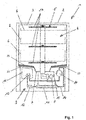
- Fig. 1 can in a purely schematic representation of a washing machine, here without limiting the general public in the form of a dishwasher 1, in particular a domestic dishwasher, recognize according to the invention.
- the dishwasher 1 has a housing 2 which, inter alia, accommodates a washing / rinsing container 3, referred to below as a rinsing container.
- the rinsing container 3 in turn provides a washing / rinsing 4, hereinafter referred to as a washing compartment, ready, which serves in the intended use of the inclusion of to be cleaned washing / Spülgut.
- a spray device 5 For loading of items to be cleaned with rinse liquor is a spray device 5, which is arranged within the washing container 3.
- a spraying device has spray arms 17, which are each arranged rotatable within the washing container 3.
- scavenging baskets 6 are used to hold the items to be cleaned, with three such scavenging baskets 6 being provided.
- the flushing chamber 4 opens into a collection pot 7, not shown in detail, of the washing container 3, to which a circulating pump 8 is fluidically connected. Via corresponding supply lines, the spraying device 5 is fluidically connected to the circulating pump 8. In the intended use case can thus take place a charging of the spray 5 with rinsing water by means of the circulation pump 8.
- the dishwasher 1 has in this embodiment of the invention further without limiting the generality of a heat pump device 9.
- This has a compressor 10, a condenser 11, an expansion device in the form of a throttle 12, an evaporator 13 and a flow component of these structural components interconnecting flow circuit 14 , in which a working medium is guided.
- the evaporator 13 is disposed within a tank 16 which is filled with water as the heat transfer medium.
- the compressor 10 present here as the heat-emitting component in the sense of the invention is preferably a roller-piston compressor, as shown schematically in FIGS. 3 and 4 is shown, but it is also possible to use about a Hubkolben- a screw, a rotary piston or a scroll compressor.
- the compressor 10 gives off waste heat in the form of heat radiation 18, as shown in the illustration Fig. 3 lets recognize. This emitted from the compressor 10 heat radiation 18 is lost to the rinsing process without the invention as waste heat.
- Fig. 1 schematically indicated, in this embodiment of the invention, essential components of the heat pump device, in particular the compressor 10, below the washing compartment 3, in particular arranged in a base region of the washing machine.
- the washing container 3 is covered at least on the underside with an insulation 23.
- Further washing / Spül electerwande may also be provided with insulation, which is not shown here for clarity.
- the underside of the washing container 3, namely on the Spül electerboden mounted insulation 23 is preferably formed water repellent. According to another feature, it can be largely dimensionally stable. In particular, their material may be or include PP nonwoven, PE, polyester nonwoven, cellular rubber or cotton nonwoven.
- the insulation 23 ensures that the washing compartment 3 does not unnecessarily give off heat to the environment.
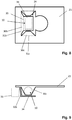
- the insulation 23 corresponds to the configuration of the compressor 10, namely at least in the area of the orthogonal projection of the compressor 10 onto the washing / rinsing container wall, in this case the rinsing container bottom 25 , equipped with a recess 24, as can be seen from the illustration Fig. 2 results.
- the insulation 23 is preferably formed as a one-piece coateddämmmatte. Their outer dimension, which has a substantially rectangular shape, is adapted to the size and geometry of the Spül electergebers 25 in order to effect the most complete isolation downwards.
- the initially rectangular heat-insulating mat is provided, for example, by punching or cutting, with the recess 24 located in this exemplary embodiment, before it is attached to the underside of the washing container.
- the second region 24b allows the passage of a functional component arranged on the rinsing container bottom 25 or connected to the rinsing container bottom 25, in the preceding case of the collecting pot 7, through the heat-insulating plate 23.
- the recess 24 on the (first) region 24 a which is the passage of the arranged in the mounted state below the heat-insulating mat 23 compressor 10, the lateral orientation in Fig.
- emitted heat radiation allows.
- a recess may instead or additionally be provided for another heat-emitting component.
- the two regions 24a and 24b of the recess 24 can be as shown here However, they can also be designed separately.
- the rinsing container 3 can preferably be equipped on the compressor side with a coating, not shown here, for example of bitumen, ie with a coating having a high emissivity, in particular of> 0.9 having. This ensures effective absorption of the heat radiation emanating from the compressor 10 through the washing container 3.
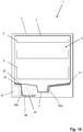
- FIGS. 5 and 6 schematically show an insulation 23, in particular a heat-insulating mat for a washing machine according to another embodiment.
- the thermal insulation mat 23 largely corresponds to the in Fig. 2 described heat insulation mat, inasmuch as the above statements apply here as well. Again, the lateral orientation of a mounted in the mounted state below the heat-insulating mat 23 compressor 10 is indicated by dashed lines.
- the thermal insulation mat differs only in the design of the recess 24, in particular of the first region 24a of the in Fig. 2 shown thermal insulation mat.
- the heat-insulating mat 23 lies largely, namely with its abutment surface region 34, on the dishwasher floor 25, but not with the one or more fold-down areas 30a, 30b, 30c, which extend along a direction away from the Spülraumboden 25, as in Fig. 6 shown.
- a fold-down region 30c extends along a front side of the compressor 10
- a fold-down region 30b extends along one longitudinal side of the compressor 10.
- the fold-down region 30b protects an adjacent component 33 of the washing machine, indicated by dashed lines, from overheating caused by the waste heat of the compressor 10 ,
- Fig. 7 shows an embodiment of a washing machine 1 according to the invention with a thermal insulation mat 23 similar to that in the.
- FIGS. 5 and 6 shown.
- Evident are a in the base region of the washing machine 1 below the Spipporaum undergraduate 25 arranged compressor 10 and in particular Abklapp Societye 30b and 30c of the thermal insulation mat 23, which extend along a direction away from Spülraum undergraduate 25 direction, wherein Abklapp Society 30c etnlang along a front and Abklapp Scheme 30b a longitudinal side of the compressor 10 extends.
- Abklapp Society 30c heat protection for the adjacent component 33 is provided.
- the representations after 8 and 9 schematically show an insulation 23, in particular a heat-insulating mat for a washing machine according to another embodiment.
- the thermal insulation mat 23 largely corresponds to the in Fig. 5, 6 and 7 described heat insulation mat, inasmuch as the above statements apply here as well.
- the thermal insulation mat differs from the in Fig. 5-7 shown thermal insulation mat that the Abklapp Siemens 30b relative to the previous embodiment has an extension.
- the thermal insulation mat 23 has a continuation region 34 following the fold-down region 30b. This can be folded down at a Abklappkante 35 from Abklapp Scheme 30b. In the assembled state, the continuation region 34 extends below the compressor 10.
- Fig. 10 shows an embodiment of a washing machine 1 according to the invention with a thermal insulation mat 23 similar to that in the.
- FIGS. 8 and 9 shown.
- the heat-insulating mat 23 has a fold-down region 30d which, in the mounted state, adjoins the collecting pot or for which it forms insulation in a partial region.
- heat protection for the adjacent component 33 is provided.
- a radiation shield is provided, which cooperates with the compressor 10.
- the radiation shield shields the surroundings of the compressor 10 from the compressor 10 at least partially.
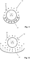
- Such a radiation shield can be formed for example by a reflector 19, as in different embodiments in the FIGS. 11, 12 and 13 is shown.
- the reflector 19 is arranged and configured to move away from the compressor 10 emitted heat radiation 18 in the direction of the compressor 10 and / or the not shown here, but arranged above the compressor recess 24 to redirect.
- the reflector 19 surrounds the housing of the compressor 10 at least partially concentric. In this case, the reflector at a distance of about 1 mm to 50 mm, more preferably from about 10 mm to 15 mm to the compressor 10 is arranged.
- An alternative embodiment shows Fig. 12 in which the reflector 19 is parabolic in the manner of a parabolic mirror.
- the reflector preferably has a mirrored surface on the compressor side.
- a mirrored surface on the compressor side for this purpose, for example, be provided to form the reflector 19 of a plastic material which is formed on the compressor side mirrored, for example by painting or by vapor deposition.
- the reflector 19 is made of a metal such as stainless steel or aluminum, wherein the compressor-side surface of the reflector 19 is polished.
- Fig. 13 shows an embodiment, according to which the reflector 19 is formed as a portion of the bottom pan 20 of the dishwasher 1.
- the separate embodiment of a reflector 19 is omitted according to this embodiment by a portion of the bottom tray 20 is formed so that it serves as a reflector 19.
- the radiation shield is formed as a coating 22, which is externally applied to the housing 21 of the compressor 10.
- a reflector, which forms the radiation shield, can instead or additionally also be provided by the thermal insulation mat 23, in particular by a fold-down region 30a, 30b, 30c, 30d, according to a further exemplary embodiment.
- a fold-down region 30a, 30b, 30c, 30d or a continuation region 34 on the side facing the compressor 10 have a heat radiation-reflecting coating, in particular a coating with a low emission coefficient of ⁇ 0.2, for example an aluminum foil.
Landscapes
- Engineering & Computer Science (AREA)
- Textile Engineering (AREA)
- Detail Structures Of Washing Machines And Dryers (AREA)
- Washing And Drying Of Tableware (AREA)
Applications Claiming Priority (1)
| Application Number | Priority Date | Filing Date | Title |
|---|---|---|---|
| DE102017111581 | 2017-05-29 |
Publications (2)
| Publication Number | Publication Date |
|---|---|
| EP3409181A1 true EP3409181A1 (fr) | 2018-12-05 |
| EP3409181B1 EP3409181B1 (fr) | 2022-03-16 |
Family
ID=62165376
Family Applications (2)
| Application Number | Title | Priority Date | Filing Date |
|---|---|---|---|
| EP18171968.3A Active EP3409179B1 (fr) | 2017-05-29 | 2018-05-14 | Machine à laver, en particulier lave-vaisselle domestique |
| EP18174552.2A Active EP3409181B1 (fr) | 2017-05-29 | 2018-05-28 | Machine à laver, en particulier lave-vaisselle domestique |
Family Applications Before (1)
| Application Number | Title | Priority Date | Filing Date |
|---|---|---|---|
| EP18171968.3A Active EP3409179B1 (fr) | 2017-05-29 | 2018-05-14 | Machine à laver, en particulier lave-vaisselle domestique |
Country Status (1)
| Country | Link |
|---|---|
| EP (2) | EP3409179B1 (fr) |
Cited By (1)
| Publication number | Priority date | Publication date | Assignee | Title |
|---|---|---|---|---|
| US11950740B2 (en) * | 2018-10-12 | 2024-04-09 | BSH Hausgeräte GmbH | Domestic appliance and method for producing a domestic appliance |
Citations (4)
| Publication number | Priority date | Publication date | Assignee | Title |
|---|---|---|---|---|
| EP2206824A2 (fr) | 2010-02-16 | 2010-07-14 | V-Zug AG | Appareil ménager doté d'une cuve, d'une pompe à chaleur et d'un réservoir |
| EP2430967A2 (fr) * | 2010-07-16 | 2012-03-21 | BSH Bosch und Siemens Hausgeräte GmbH | Appareil ménager doté d'au moins un revêtement d'amortissement et/ou d'insonorisation ainsi que procédé de fabrication correspondant |
| EP2682038A2 (fr) | 2012-07-03 | 2014-01-08 | Miele & Cie. KG | Lave-vaisselle et procédé de fonctionnement d'un lave-vaisselle |
| DE102014200774A1 (de) * | 2014-01-17 | 2015-07-23 | BSH Hausgeräte GmbH | Waschmaschine mit Riemenantrieb und verbesserter Nutzung der Motorverlustleistung |
Family Cites Families (2)
| Publication number | Priority date | Publication date | Assignee | Title |
|---|---|---|---|---|
| AT506553A1 (de) * | 2008-03-27 | 2009-10-15 | Herbert Karlsreiter | Wärmepumpenwaschtrockner |
| PL3261509T3 (pl) * | 2015-02-27 | 2019-10-31 | Bsh Hausgeraete Gmbh | Zmywarka do naczyń gospodarstwa domowego do mycia przedmiotów do zmywania w jednym lub w kilku częściowych cyklach zmywania i przynależny sposób |
-
2018
- 2018-05-14 EP EP18171968.3A patent/EP3409179B1/fr active Active
- 2018-05-28 EP EP18174552.2A patent/EP3409181B1/fr active Active
Patent Citations (4)
| Publication number | Priority date | Publication date | Assignee | Title |
|---|---|---|---|---|
| EP2206824A2 (fr) | 2010-02-16 | 2010-07-14 | V-Zug AG | Appareil ménager doté d'une cuve, d'une pompe à chaleur et d'un réservoir |
| EP2430967A2 (fr) * | 2010-07-16 | 2012-03-21 | BSH Bosch und Siemens Hausgeräte GmbH | Appareil ménager doté d'au moins un revêtement d'amortissement et/ou d'insonorisation ainsi que procédé de fabrication correspondant |
| EP2682038A2 (fr) | 2012-07-03 | 2014-01-08 | Miele & Cie. KG | Lave-vaisselle et procédé de fonctionnement d'un lave-vaisselle |
| DE102014200774A1 (de) * | 2014-01-17 | 2015-07-23 | BSH Hausgeräte GmbH | Waschmaschine mit Riemenantrieb und verbesserter Nutzung der Motorverlustleistung |
Cited By (1)
| Publication number | Priority date | Publication date | Assignee | Title |
|---|---|---|---|---|
| US11950740B2 (en) * | 2018-10-12 | 2024-04-09 | BSH Hausgeräte GmbH | Domestic appliance and method for producing a domestic appliance |
Also Published As
| Publication number | Publication date |
|---|---|
| EP3409181B1 (fr) | 2022-03-16 |
| EP3409179B1 (fr) | 2019-11-27 |
| EP3409179A1 (fr) | 2018-12-05 |
Similar Documents
| Publication | Publication Date | Title |
|---|---|---|
| EP1791459B1 (fr) | Procédé de séchage pour un appareil électroménager et appareil électroménager | |
| DE102019131954B4 (de) | Geschirrspülmaschine mit Wärmepumpe | |
| DE102019131918A1 (de) | Geschirrspülmaschine mit Wärmepumpe | |
| WO2017195057A1 (fr) | Lave-vaisselle et procédé pour nettoyer et sécher de la vaisselle | |
| DE102019131960A1 (de) | Geschirrspülmaschine mit Wärmepumpe | |
| DE202008011159U1 (de) | Geschirrspülmaschine und Sorptionstrockenvorrichtung, deren Sorptionsmaterial gewichtsmäßig an die Benetzungsmenge im Spülraum angepasst ist | |
| DE19813924A1 (de) | Kondensationseinrichtung und Verfahren für den Betrieb derselben | |
| EP1673002B1 (fr) | Lave-vaisselle dote d'un dispositif de sechage | |
| DE102013213359B3 (de) | Verfahren zum Betreiben einer Spülmaschine sowie Spülmaschine | |
| DE102012212636B4 (de) | Gewerbliche Spülmaschine mit Trocknungssystem sowie Verfahren zum Betreiben einer solchen Spülmaschine | |
| EP3409181B1 (fr) | Machine à laver, en particulier lave-vaisselle domestique | |
| DE102019131958B4 (de) | Geschirrspülmaschine mit Wärmepumpe | |
| EP3505040B1 (fr) | Lave-vaisselle, en particulier lave-vaisselle électroménager | |
| EP3718461A1 (fr) | Lave-vaisselle, en particulier lave-vaisselle électroménager | |
| EP3629877B1 (fr) | Lave-vaisselle, en particulier lave-vaisselle électroménager | |
| DE102016103921A1 (de) | Geschirrspülmaschine | |
| EP2574267B1 (fr) | Appareil ménager, notamment lave-vaisselle | |
| EP3643217B1 (fr) | Prévention de la condensation de vapeur d'eau sur le mur extérieur d'un lave-vaisselle ménager | |
| DE102019131932A1 (de) | Geschirrspülmaschine mit Wärmepumpe | |
| DE102015206331A1 (de) | Als Programmautomat ausgeführte gewerbliche Spülmaschine sowie Verfahren zum Betreiben einer solchen Spülmaschine | |
| EP3369357B1 (fr) | Appareil électroménager à circulation d'eau et procédé de fonctionnement d'un électroménager à circulation d'eau | |
| EP3170438B1 (fr) | Lave-vaisselle comprenant une pompe à chaleur | |
| EP3622876B1 (fr) | Lave-vaisselle, en particulier lave-vaisselle électroménager | |
| EP3021728B1 (fr) | Lave-vaisselle comprenant une partie de conduite tubulaire d'évacuation intégrée dans un récipient d'eau | |
| DE102013210468B3 (de) | Verfahren zum Betreiben einer Spülmaschine sowie Spülmaschine |
Legal Events
| Date | Code | Title | Description |
|---|---|---|---|
| PUAI | Public reference made under article 153(3) epc to a published international application that has entered the european phase |
Free format text: ORIGINAL CODE: 0009012 |
|
| STAA | Information on the status of an ep patent application or granted ep patent |
Free format text: STATUS: THE APPLICATION HAS BEEN PUBLISHED |
|
| AK | Designated contracting states |
Kind code of ref document: A1 Designated state(s): AL AT BE BG CH CY CZ DE DK EE ES FI FR GB GR HR HU IE IS IT LI LT LU LV MC MK MT NL NO PL PT RO RS SE SI SK SM TR |
|
| AX | Request for extension of the european patent |
Extension state: BA ME |
|
| STAA | Information on the status of an ep patent application or granted ep patent |
Free format text: STATUS: REQUEST FOR EXAMINATION WAS MADE |
|
| 17P | Request for examination filed |
Effective date: 20190516 |
|
| RBV | Designated contracting states (corrected) |
Designated state(s): AL AT BE BG CH CY CZ DE DK EE ES FI FR GB GR HR HU IE IS IT LI LT LU LV MC MK MT NL NO PL PT RO RS SE SI SK SM TR |
|
| REG | Reference to a national code |
Ref country code: DE Ref legal event code: R079 Ref document number: 502018009079 Country of ref document: DE Free format text: PREVIOUS MAIN CLASS: A47L0015420000 Ipc: D06F0039000000 |
|
| GRAP | Despatch of communication of intention to grant a patent |
Free format text: ORIGINAL CODE: EPIDOSNIGR1 |
|
| STAA | Information on the status of an ep patent application or granted ep patent |
Free format text: STATUS: GRANT OF PATENT IS INTENDED |
|
| RIC1 | Information provided on ipc code assigned before grant |
Ipc: A47L 15/42 20060101ALI20211006BHEP Ipc: D06F 39/00 20200101AFI20211006BHEP |
|
| INTG | Intention to grant announced |
Effective date: 20211109 |
|
| GRAS | Grant fee paid |
Free format text: ORIGINAL CODE: EPIDOSNIGR3 |
|
| GRAA | (expected) grant |
Free format text: ORIGINAL CODE: 0009210 |
|
| STAA | Information on the status of an ep patent application or granted ep patent |
Free format text: STATUS: THE PATENT HAS BEEN GRANTED |
|
| AK | Designated contracting states |
Kind code of ref document: B1 Designated state(s): AL AT BE BG CH CY CZ DE DK EE ES FI FR GB GR HR HU IE IS IT LI LT LU LV MC MK MT NL NO PL PT RO RS SE SI SK SM TR |
|
| REG | Reference to a national code |
Ref country code: GB Ref legal event code: FG4D Free format text: NOT ENGLISH |
|
| REG | Reference to a national code |
Ref country code: CH Ref legal event code: EP Ref country code: DE Ref legal event code: R096 Ref document number: 502018009079 Country of ref document: DE |
|
| REG | Reference to a national code |
Ref country code: IE Ref legal event code: FG4D Free format text: LANGUAGE OF EP DOCUMENT: GERMAN |
|
| REG | Reference to a national code |
Ref country code: AT Ref legal event code: REF Ref document number: 1475946 Country of ref document: AT Kind code of ref document: T Effective date: 20220415 |
|
| REG | Reference to a national code |
Ref country code: DE Ref legal event code: R084 Ref document number: 502018009079 Country of ref document: DE |
|
| REG | Reference to a national code |
Ref country code: GB Ref legal event code: 746 Effective date: 20220606 |
|
| REG | Reference to a national code |
Ref country code: LT Ref legal event code: MG9D |
|
| REG | Reference to a national code |
Ref country code: NL Ref legal event code: MP Effective date: 20220316 |
|
| PG25 | Lapsed in a contracting state [announced via postgrant information from national office to epo] |
Ref country code: SE Free format text: LAPSE BECAUSE OF FAILURE TO SUBMIT A TRANSLATION OF THE DESCRIPTION OR TO PAY THE FEE WITHIN THE PRESCRIBED TIME-LIMIT Effective date: 20220316 Ref country code: RS Free format text: LAPSE BECAUSE OF FAILURE TO SUBMIT A TRANSLATION OF THE DESCRIPTION OR TO PAY THE FEE WITHIN THE PRESCRIBED TIME-LIMIT Effective date: 20220316 Ref country code: NO Free format text: LAPSE BECAUSE OF FAILURE TO SUBMIT A TRANSLATION OF THE DESCRIPTION OR TO PAY THE FEE WITHIN THE PRESCRIBED TIME-LIMIT Effective date: 20220616 Ref country code: LT Free format text: LAPSE BECAUSE OF FAILURE TO SUBMIT A TRANSLATION OF THE DESCRIPTION OR TO PAY THE FEE WITHIN THE PRESCRIBED TIME-LIMIT Effective date: 20220316 Ref country code: HR Free format text: LAPSE BECAUSE OF FAILURE TO SUBMIT A TRANSLATION OF THE DESCRIPTION OR TO PAY THE FEE WITHIN THE PRESCRIBED TIME-LIMIT Effective date: 20220316 Ref country code: BG Free format text: LAPSE BECAUSE OF FAILURE TO SUBMIT A TRANSLATION OF THE DESCRIPTION OR TO PAY THE FEE WITHIN THE PRESCRIBED TIME-LIMIT Effective date: 20220616 |
|
| PG25 | Lapsed in a contracting state [announced via postgrant information from national office to epo] |
Ref country code: LV Free format text: LAPSE BECAUSE OF FAILURE TO SUBMIT A TRANSLATION OF THE DESCRIPTION OR TO PAY THE FEE WITHIN THE PRESCRIBED TIME-LIMIT Effective date: 20220316 Ref country code: GR Free format text: LAPSE BECAUSE OF FAILURE TO SUBMIT A TRANSLATION OF THE DESCRIPTION OR TO PAY THE FEE WITHIN THE PRESCRIBED TIME-LIMIT Effective date: 20220617 Ref country code: FI Free format text: LAPSE BECAUSE OF FAILURE TO SUBMIT A TRANSLATION OF THE DESCRIPTION OR TO PAY THE FEE WITHIN THE PRESCRIBED TIME-LIMIT Effective date: 20220316 |
|
| PG25 | Lapsed in a contracting state [announced via postgrant information from national office to epo] |
Ref country code: NL Free format text: LAPSE BECAUSE OF FAILURE TO SUBMIT A TRANSLATION OF THE DESCRIPTION OR TO PAY THE FEE WITHIN THE PRESCRIBED TIME-LIMIT Effective date: 20220316 |
|
| PG25 | Lapsed in a contracting state [announced via postgrant information from national office to epo] |
Ref country code: SM Free format text: LAPSE BECAUSE OF FAILURE TO SUBMIT A TRANSLATION OF THE DESCRIPTION OR TO PAY THE FEE WITHIN THE PRESCRIBED TIME-LIMIT Effective date: 20220316 Ref country code: SK Free format text: LAPSE BECAUSE OF FAILURE TO SUBMIT A TRANSLATION OF THE DESCRIPTION OR TO PAY THE FEE WITHIN THE PRESCRIBED TIME-LIMIT Effective date: 20220316 Ref country code: RO Free format text: LAPSE BECAUSE OF FAILURE TO SUBMIT A TRANSLATION OF THE DESCRIPTION OR TO PAY THE FEE WITHIN THE PRESCRIBED TIME-LIMIT Effective date: 20220316 Ref country code: PT Free format text: LAPSE BECAUSE OF FAILURE TO SUBMIT A TRANSLATION OF THE DESCRIPTION OR TO PAY THE FEE WITHIN THE PRESCRIBED TIME-LIMIT Effective date: 20220718 Ref country code: ES Free format text: LAPSE BECAUSE OF FAILURE TO SUBMIT A TRANSLATION OF THE DESCRIPTION OR TO PAY THE FEE WITHIN THE PRESCRIBED TIME-LIMIT Effective date: 20220316 Ref country code: EE Free format text: LAPSE BECAUSE OF FAILURE TO SUBMIT A TRANSLATION OF THE DESCRIPTION OR TO PAY THE FEE WITHIN THE PRESCRIBED TIME-LIMIT Effective date: 20220316 Ref country code: CZ Free format text: LAPSE BECAUSE OF FAILURE TO SUBMIT A TRANSLATION OF THE DESCRIPTION OR TO PAY THE FEE WITHIN THE PRESCRIBED TIME-LIMIT Effective date: 20220316 |
|
| PG25 | Lapsed in a contracting state [announced via postgrant information from national office to epo] |
Ref country code: PL Free format text: LAPSE BECAUSE OF FAILURE TO SUBMIT A TRANSLATION OF THE DESCRIPTION OR TO PAY THE FEE WITHIN THE PRESCRIBED TIME-LIMIT Effective date: 20220316 Ref country code: IS Free format text: LAPSE BECAUSE OF FAILURE TO SUBMIT A TRANSLATION OF THE DESCRIPTION OR TO PAY THE FEE WITHIN THE PRESCRIBED TIME-LIMIT Effective date: 20220716 Ref country code: AL Free format text: LAPSE BECAUSE OF FAILURE TO SUBMIT A TRANSLATION OF THE DESCRIPTION OR TO PAY THE FEE WITHIN THE PRESCRIBED TIME-LIMIT Effective date: 20220316 |
|
| REG | Reference to a national code |
Ref country code: DE Ref legal event code: R097 Ref document number: 502018009079 Country of ref document: DE |
|
| REG | Reference to a national code |
Ref country code: CH Ref legal event code: PL |
|
| PLBE | No opposition filed within time limit |
Free format text: ORIGINAL CODE: 0009261 |
|
| STAA | Information on the status of an ep patent application or granted ep patent |
Free format text: STATUS: NO OPPOSITION FILED WITHIN TIME LIMIT |
|
| REG | Reference to a national code |
Ref country code: BE Ref legal event code: MM Effective date: 20220531 |
|
| PG25 | Lapsed in a contracting state [announced via postgrant information from national office to epo] |
Ref country code: MC Free format text: LAPSE BECAUSE OF FAILURE TO SUBMIT A TRANSLATION OF THE DESCRIPTION OR TO PAY THE FEE WITHIN THE PRESCRIBED TIME-LIMIT Effective date: 20220316 Ref country code: LU Free format text: LAPSE BECAUSE OF NON-PAYMENT OF DUE FEES Effective date: 20220528 Ref country code: LI Free format text: LAPSE BECAUSE OF NON-PAYMENT OF DUE FEES Effective date: 20220531 Ref country code: DK Free format text: LAPSE BECAUSE OF FAILURE TO SUBMIT A TRANSLATION OF THE DESCRIPTION OR TO PAY THE FEE WITHIN THE PRESCRIBED TIME-LIMIT Effective date: 20220316 Ref country code: CH Free format text: LAPSE BECAUSE OF NON-PAYMENT OF DUE FEES Effective date: 20220531 |
|
| 26N | No opposition filed |
Effective date: 20221219 |
|
| PG25 | Lapsed in a contracting state [announced via postgrant information from national office to epo] |
Ref country code: SI Free format text: LAPSE BECAUSE OF FAILURE TO SUBMIT A TRANSLATION OF THE DESCRIPTION OR TO PAY THE FEE WITHIN THE PRESCRIBED TIME-LIMIT Effective date: 20220316 |
|
| PG25 | Lapsed in a contracting state [announced via postgrant information from national office to epo] |
Ref country code: IE Free format text: LAPSE BECAUSE OF NON-PAYMENT OF DUE FEES Effective date: 20220528 |
|
| PG25 | Lapsed in a contracting state [announced via postgrant information from national office to epo] |
Ref country code: BE Free format text: LAPSE BECAUSE OF NON-PAYMENT OF DUE FEES Effective date: 20220531 |
|
| P01 | Opt-out of the competence of the unified patent court (upc) registered |
Effective date: 20230528 |
|
| PG25 | Lapsed in a contracting state [announced via postgrant information from national office to epo] |
Ref country code: HU Free format text: LAPSE BECAUSE OF FAILURE TO SUBMIT A TRANSLATION OF THE DESCRIPTION OR TO PAY THE FEE WITHIN THE PRESCRIBED TIME-LIMIT; INVALID AB INITIO Effective date: 20180528 |
|
| PG25 | Lapsed in a contracting state [announced via postgrant information from national office to epo] |
Ref country code: MK Free format text: LAPSE BECAUSE OF FAILURE TO SUBMIT A TRANSLATION OF THE DESCRIPTION OR TO PAY THE FEE WITHIN THE PRESCRIBED TIME-LIMIT Effective date: 20220316 Ref country code: CY Free format text: LAPSE BECAUSE OF FAILURE TO SUBMIT A TRANSLATION OF THE DESCRIPTION OR TO PAY THE FEE WITHIN THE PRESCRIBED TIME-LIMIT Effective date: 20220316 |
|
| REG | Reference to a national code |
Ref country code: AT Ref legal event code: MM01 Ref document number: 1475946 Country of ref document: AT Kind code of ref document: T Effective date: 20230528 |
|
| PG25 | Lapsed in a contracting state [announced via postgrant information from national office to epo] |
Ref country code: AT Free format text: LAPSE BECAUSE OF NON-PAYMENT OF DUE FEES Effective date: 20230528 |
|
| PG25 | Lapsed in a contracting state [announced via postgrant information from national office to epo] |
Ref country code: AT Free format text: LAPSE BECAUSE OF NON-PAYMENT OF DUE FEES Effective date: 20230528 |
|
| PG25 | Lapsed in a contracting state [announced via postgrant information from national office to epo] |
Ref country code: MT Free format text: LAPSE BECAUSE OF FAILURE TO SUBMIT A TRANSLATION OF THE DESCRIPTION OR TO PAY THE FEE WITHIN THE PRESCRIBED TIME-LIMIT Effective date: 20220316 |
|
| PGFP | Annual fee paid to national office [announced via postgrant information from national office to epo] |
Ref country code: DE Payment date: 20250531 Year of fee payment: 8 |
|
| PGFP | Annual fee paid to national office [announced via postgrant information from national office to epo] |
Ref country code: IT Payment date: 20250522 Year of fee payment: 8 |
|
| PGFP | Annual fee paid to national office [announced via postgrant information from national office to epo] |
Ref country code: FR Payment date: 20250526 Year of fee payment: 8 |
|
| PGFP | Annual fee paid to national office [announced via postgrant information from national office to epo] |
Ref country code: TR Payment date: 20250515 Year of fee payment: 8 |
|
| PGFP | Annual fee paid to national office [announced via postgrant information from national office to epo] |
Ref country code: GB Payment date: 20260313 Year of fee payment: 9 |
|
| PGFP | Annual fee paid to national office [announced via postgrant information from national office to epo] |
Ref country code: AT Payment date: 20260410 Year of fee payment: 5 |