EP3409582A1 - Halbgehebeltes schrumpffahrwerk - Google Patents
Halbgehebeltes schrumpffahrwerk Download PDFInfo
- Publication number
- EP3409582A1 EP3409582A1 EP18173205.8A EP18173205A EP3409582A1 EP 3409582 A1 EP3409582 A1 EP 3409582A1 EP 18173205 A EP18173205 A EP 18173205A EP 3409582 A1 EP3409582 A1 EP 3409582A1
- Authority
- EP
- European Patent Office
- Prior art keywords
- landing gear
- shrink
- outer sleeve
- shock strut
- coupled
- Prior art date
- Legal status (The legal status is an assumption and is not a legal conclusion. Google has not performed a legal analysis and makes no representation as to the accuracy of the status listed.)
- Granted
Links
Images







Classifications
-
- B—PERFORMING OPERATIONS; TRANSPORTING
- B64—AIRCRAFT; AVIATION; COSMONAUTICS
- B64C—AEROPLANES; HELICOPTERS
- B64C25/00—Alighting gear
- B64C25/02—Undercarriages
- B64C25/04—Arrangement or disposition on aircraft
-
- B—PERFORMING OPERATIONS; TRANSPORTING
- B64—AIRCRAFT; AVIATION; COSMONAUTICS
- B64C—AEROPLANES; HELICOPTERS
- B64C25/00—Alighting gear
- B64C25/02—Undercarriages
- B64C25/08—Undercarriages non-fixed, e.g. jettisonable
- B64C25/10—Undercarriages non-fixed, e.g. jettisonable retractable, foldable, or the like
-
- B—PERFORMING OPERATIONS; TRANSPORTING
- B64—AIRCRAFT; AVIATION; COSMONAUTICS
- B64C—AEROPLANES; HELICOPTERS
- B64C25/00—Alighting gear
- B64C25/02—Undercarriages
- B64C25/08—Undercarriages non-fixed, e.g. jettisonable
- B64C25/10—Undercarriages non-fixed, e.g. jettisonable retractable, foldable, or the like
- B64C25/14—Undercarriages non-fixed, e.g. jettisonable retractable, foldable, or the like fore-and-aft
-
- B—PERFORMING OPERATIONS; TRANSPORTING
- B64—AIRCRAFT; AVIATION; COSMONAUTICS
- B64C—AEROPLANES; HELICOPTERS
- B64C25/00—Alighting gear
- B64C25/02—Undercarriages
- B64C25/08—Undercarriages non-fixed, e.g. jettisonable
- B64C25/10—Undercarriages non-fixed, e.g. jettisonable retractable, foldable, or the like
- B64C25/18—Operating mechanisms
- B64C25/20—Operating mechanisms mechanical
-
- B—PERFORMING OPERATIONS; TRANSPORTING
- B64—AIRCRAFT; AVIATION; COSMONAUTICS
- B64C—AEROPLANES; HELICOPTERS
- B64C25/00—Alighting gear
- B64C25/32—Alighting gear characterised by elements which contact the ground or similar surface
- B64C25/34—Alighting gear characterised by elements which contact the ground or similar surface wheeled type, e.g. multi-wheeled bogies
-
- B—PERFORMING OPERATIONS; TRANSPORTING
- B64—AIRCRAFT; AVIATION; COSMONAUTICS
- B64C—AEROPLANES; HELICOPTERS
- B64C25/00—Alighting gear
- B64C25/32—Alighting gear characterised by elements which contact the ground or similar surface
- B64C25/58—Arrangements or adaptations of shock-absorbers or springs
- B64C25/60—Oleo legs
-
- B—PERFORMING OPERATIONS; TRANSPORTING
- B64—AIRCRAFT; AVIATION; COSMONAUTICS
- B64C—AEROPLANES; HELICOPTERS
- B64C25/00—Alighting gear
- B64C25/001—Devices not provided for in the groups B64C25/02 - B64C25/68
- B64C2025/008—Comprising means for modifying their length, e.g. for kneeling, for jumping, or for leveling the aircraft
Definitions
- the aspects of the present disclosure generally relate to an aircraft landing gear and more particularly to semi-levered shrink landing gear.
- Aircraft with one or more of large engine fan diameters, long fuselages, long wings, and specialized under-aircraft payload may use a tall landing gear structure to provide ground clearance to the engine and sufficient clearance during take-off.
- a tall landing gear structure For example, during take-off, the nose of an aircraft rotates upward and the tail rotates downward to achieve an angle-of-attack at take-off. The longer the aircraft, the taller the landing gear is to achieve the take-off angle-of-attack. The taller the landing gear, the higher the angle-of-attack.
- Integrating longer/taller landing gear structures into the aircraft may impose expensive design constraints on the aircraft and also may add weight, which in turn requires greater fuel consumption by the aircraft.
- lengthening the landing gear increases the static height of the aircraft and may require the use of over-wing slides integrated into the aircraft and/or a larger wheel well (noting larger wheel wells may not be possible without redesigning the aircraft).
- Landing gear structures on aircraft generally employ an OLEO (i.e., pneumatic air-oil hydraulic) shock strut, in which a piston compresses a volume that includes both a compressible gas and a substantially incompressible liquid.
- OLEO i.e., pneumatic air-oil hydraulic
- landing gear structures include a main fitting (e.g., an outer tube), a piston (e.g., an inner tube), and a sliding tube cylinder, thus involving three tubes/cylinders.
- a landing gear structure that includes an OLEO shock strut may be compressed into a retracted configuration for stowage in the wheel well during flight.
- achieving the retracted configuration may require compressing the compressible gas to an undesirably high pressure.
- such landing gear including mechanisms to compress the OLEO shock strut tend to be heavy and complex, thus creating potential disadvantages from aircraft efficiency, maintenance, and manufacture standpoints.
- pivoting truck levers are employed with a linkage mechanism that pivots the truck lever to shorten a length of the landing gear upon retraction of the landing gear.
- the linkage mechanism is generally coupled to the structure of the landing gear, which landing gear structure drives the linkage mechanism to pivot the truck lever.
- a shrink mechanism for use with a landing gear of an aircraft, the landing gear including an outer sleeve at least partially surrounding a shock strut
- the shrink mechanism comprising: a shaft rotatably coupled to the outer sleeve about a shaft rotation axis, the shaft being disposed perpendicular to a centerline of the shock strut; an anchor arm coupled to the shaft, the anchor arm being configured to couple to a structure within a wing of the aircraft; a shrink arm coupled to the shaft, the shrink arm and the anchor arm being coupled to the shaft so as to rotate as a unit with the shaft about the shaft rotation axis; and a shrink link rotatably coupled to the shrink arm, the shrink link being configured to rotatably couple to the shock strut.
- a landing gear for use on an aircraft, the landing gear comprising: an outer sleeve; a shock strut positioned at least partially within the outer sleeve; and a shrink mechanism coupled to the outer sleeve and the shock strut, the shrink mechanism being configured to move the shock strut relative to the outer sleeve, the shrink mechanism including a shaft rotatably coupled to the outer sleeve about a shaft rotation axis, the shaft being disposed perpendicular to a centerline of the shock strut; an anchor arm coupled to the shaft, the anchor arm being configured to couple to a structure within a wing of the aircraft; a shrink arm coupled to the shaft, the shrink arm and the anchor arm being coupled to the shaft so as to rotate as a unit with the shaft about the shaft rotation axis; and a shrink link rotatably coupled to the shrink arm, the shrink link being configured to rotatably couple to the shock strut.
- Still another example of the subject matter according to the present disclosure relates to an aircraft comprising: a landing gear including a shock strut and an outer sleeve at least partially surrounding the shock strut; and a shrink mechanism coupled to the outer sleeve and the shock strut, the shrink mechanism being configured to move the shock strut relative to the outer sleeve, the shrink mechanism including a shaft rotatably coupled to the outer sleeve about a shaft rotation axis, the shaft being disposed perpendicular to a centerline of the shock strut, an anchor arm coupled to the shaft, the anchor arm being configured to couple to a structure within a wing of the aircraft, a shrink arm coupled to the shaft, the shrink arm and the anchor arm being coupled to the shaft so as to rotate as a unit with the shaft about the shaft rotation axis, and a shrink link rotatably coupled to the shrink arm, the shrink link being configured to rotatably couple to the shock strut.
- Still another example of the subject matter according to the present disclosure relates to a method of operating a landing gear of an aircraft, the method comprising: rotating the landing gear about a trunnion axis of rotation, the trunnion axis of rotation being defined by an outer sleeve of the landing gear; and moving a shock strut relative to the outer sleeve with a shrink mechanism, where the outer sleeve at least partially surrounds the shock strut and the shrink mechanism includes: a shaft rotatably coupled to the outer sleeve about a shaft rotation axis, the shaft being disposed perpendicular to a centerline of the shock strut, an anchor arm coupled to the shaft, the anchor arm being configured to couple to a structure within a wing of the aircraft, a shrink arm coupled to the shaft, the shrink arm and the anchor arm being coupled to the shaft so as to rotate as a unit with the shaft about the shaft rotation axis, and a shrink link rotatably coupled to the shrink arm
- Still another example of the subject matter according to the present disclosure relates to an anti-rotation linkage for use with a landing gear having an outer sleeve and a shock strut positioned at least partially within the outer sleeve, the anti-rotation linkage comprising: a connector plate coupled to the shock strut; and an anti-rotation link assembly coupled to both the outer sleeve and the connector plate, the anti-rotation link assembly being configured to maintain the shock strut in a fixed rotational orientation relative to the outer sleeve.
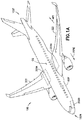
- an aircraft 100 generally includes an airframe 100F, wings 322, main landing gear 200A, and nose landing gear 200B.
- the nose 100N of the aircraft 100 rotates upward and the tail 100T rotates downward to achieve an angle-of-attack AOA at take-off.
- Lengthening the landing gear can cause at least a couple of issues. For example, if the aircraft 100 is more than six (6) feet (1.8 meters (m)) off of the ground, the aircraft 100 must include over-wing slides integrated into the aircraft 100. Further, longer landing gear has an associated a larger wheel well, which may require costly redesign of the aircraft 100.
- At least some landing gear is designed to extend and retract to obtain the benefits of longer landing gear while maintaining the same landing gear length on the ground (e.g., conventional ride height) and in the wheel well compared to conventional landing gear CSS ( Fig. 1C ) having a single shock strut (which includes an outer cylinder CSSO and an inner cylinder CSSI and a single wheel axle CWA coupled to the inner cylinder).
- the landing gear designed to extend and retract to obtain the benefits of longer landing gear, while maintaining the convention ride height includes complex mechanisms within the shock strut to extend and retract the landing gear to achieve the additional landing gear length at take-off.
- the more complex mechanisms within the landing gear allow all of the landing gear components to be contained within the landing gear (e.g., the complex mechanisms are coupled only to the structure of the landing gear).
- such complex mechanisms may include a shrink link that attaches to a walking beam of the landing gear. While this simplifies the interface to the airframe 100F structure, it can also limit the amount of rotation of the shrink link, thus limiting an amount of retraction/extension of the shock strut provided by the shrink link.
- the aspects of the present disclosure preferably overcome the deficiencies of conventional landing gear as well as improve on the landing gear designed to extend and retract to obtain the benefits of longer landing gear (e.g., with complex shrink mechanisms carried by and coupled only to components of the landing gear).
- the aspects of the present disclosure provide a landing gear 200A that includes a shrink mechanism that increases a length of the landing gear 200A when the landing gear 200A is extended and decreases the length of the landing gear 200A when the landing gear is retracted into a stowage position within the aircraft 100.
- the shrink mechanism of the landing gear 200A preferably couples (or grounds) to the wing structure rather than being coupled (or grounded) to another component of the landing gear 200A (e.g., such as a retract actuator or walking beam of the landing gear) as will be described in greater detail herein.
- Coupling the shrink mechanism of the present disclosure to the wing structure independent of (e.g., outside of) the landing gear 200A provides the shrink mechanism with an increased rotation (compared to shrink mechanisms grounded to the landing gear structure) so that a shock strut coupled to the shrink mechanism can be retracted/extended a greater distance compared to a distance of retraction/extension of the shrink mechanisms grounded to the landing gear structure.
- the shrink mechanism in accordance with the aspects of the present disclosure by virtue of the increased rotation of the shrink mechanism, can be used with a shortened conventional shock strut, rather than having complex inner workings in the shock strut.
- the landing gear 200A includes preferably a semi-levered (trailing arm) suspension that includes a conventional OLEO (a pneumatic air-oil hydraulic) shock strut that is extended and retracted as a unit by a shrink mechanism, where the shrink mechanism is grounded to a structure of the respective wing 322 of the aircraft 100. Grounding the shrink mechanism to the structure of the respective wing 322 provides the shrink mechanism with at least 180 degrees of rotation for extending and retracting the OLEO shock strut.
- OLEO pneumatic air-oil hydraulic shock strut
- the landing gear 200A including the shrink mechanism in accordance with the aspects of the present disclosure, preferably provides a landing gear 200A that is designed to extend and retract to obtain the benefits of longer landing gear, while maintaining the conventional ride height and conventional length in the wheel well (when compared to, e.g., conventional landing gear CSS illustrated in Fig. 1C ), with only one OLEO shock strut.
- the landing gear 200A with the shrink mechanism of the aspects of the present disclosure can provide for higher reliability and less complexity compared to other attempts at increasing the length of aircraft landing gear with complex mechanisms.
- the shrink mechanism of the landing gear 200A is preferably a two-dimensional mechanism (e.g., the shrink mechanism acts substantially only in a single plane of the aircraft 100).
- the landing gear of the present disclosure also avoids or reduces large bending loads introduced into the OLEO shock strut.
- the shrink mechanism enables a top-of-strut seal to reduce or substantially eliminate any debris accumulation within the landing gear 200A.
- the aspects of the present disclosure may also provide the landing gear 200A with an anti-rotation linkage 366 (see, e.g., Fig. 4 ) that prevents the OLEO shock strut 210 ( Fig. 4 ) from rotating with respect to the shrink mechanism 300 (see, e.g., Fig. 4 ) and, for example, an outer sleeve 310 (see, e.g., Fig. 4 ) of the landing gear (as described in greater detail herein). More specifically, the anti-rotation linkage 366 preferably couples to both the outer sleeve 310 and an outer cylinder 368 (see, e.g., Fig.
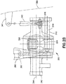
- the landing gear 200A includes a shrink mechanism 300 coupled to (e.g., grounded) to any suitable structure 320 of a respective wing 322, where the structure 322 is disposed within the wing and is separate and distinct from the landing gear 200.
- the structure 320 is a rear spar 350 of the respective wing 322.
- the landing gear 200A includes an outer sleeve 310, a shock strut 210, and the shrink mechanism 300.
- the outer sleeve 310 preferably forms an opening 354 that extends along longitudinal axis 316.
- the outer sleeve 310 is coupled to a trunnion 342 of the landing gear 200A where the trunnion 342 is coupled to the structure 320 of the wing 322 for rotation about rotation axis 344.
- the outer sleeve 310 and the trunnion 342 are integrally formed as a one piece monolithic member.
- the shock strut 210 preferably includes an outer cylinder 368 and an inner cylinder 374, and is disposed at least partially within the opening 354 so that a longitudinal axis 316' of the shock strut 210 is substantially coincident with the longitudinal axis 316 of the outer sleeve 310.
- the longitudinal axis 316, 316' is considered a centerline of the shock strut 210.
- the opening 354 is preferably configured so that the shock strut 210 linearly moves along the longitudinal axis 316 within the opening 354 as will be described herein.
- a walking beam 390 and retract actuator 392 are coupled to trunnion 342 in a conventional manner to retract the landing gear 200A to a stowage position within the aircraft 100 ( Fig. 1 ).
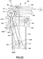
- the shrink mechanism 300 is provided for use with the landing gear 200A of the aircraft 100 ( Fig. 1 ), where the landing gear 200A includes the outer sleeve 310, which at least partially surrounds the shock strut 210.
- the shrink mechanism 300 preferably includes a shaft 312, a shrink link 326, and a rod 340.
- the shaft 312 is rotatably coupled to the outer sleeve 310 in any suitable manner for rotation about a shaft rotation axis 314.
- the shaft rotation axis 314 is spatially arranged relative to the outer sleeve 310 so as to be substantially perpendicular to the longitudinal axis 316 of the outer sleeve 310, as well as the longitudinal axis 316' of the shock strut 210.
- the shaft 312 includes an anchor arm 318 that is coupled to the shaft 312 in any suitable manner.
- the anchor arm 318 is integrally formed with the shaft as a one piece monolithic member.
- the anchor arm 318 is preferably configured to couple to the structure 320 within the respective wing 322 of the aircraft 100 in any suitable manner, such as through the rod 340.
- the shaft 312 preferably also includes a shrink arm 324 that is coupled to the shaft 312 in any suitable manner.
- the shrink arm 324 is integrally formed with the shaft 312 as a one piece monolithic member.
- the coupling between each of the shrink arm 324 and the anchor arm 318 with the shaft 312 is preferably such that both the shrink arm 324 and the anchor arm 318 rotate as a unit with the shaft 312 about the shaft rotation axis 314.
- the shrink arm 324 and anchor arm 318 may be arranged at any suitable angle ⁇ relative to one another, where the angle ⁇ may depend on a grounding location of the rod (e.g. inboard, outboard, etc.) on the structure 320 of the respective wing 322.
- the rod 340 preferably includes a first end 340E1 and a second end 340E2 that is longitudinally spaced from the first end 340E1.
- the first end 340E1 of the rod 340 is pivotally coupled to the anchor arm 318.
- the second end 340E2 of the rod 340 is pivotally coupled to the structure 320 of the respective wing 322 in any suitable manner.
- the wing structure 322 may include any suitable stanchion or protrusion 341 to which the second end 340E2 of the rod 340 is pivotally coupled. It is noted that while the rod 340 extends from the anchor arm 318 in an outboard direction, in other aspects the rod 340 may extend in an inboard direction for coupling to the structure 320 of the respective wing 322 in a manner substantially similar to that described above.
- the shrink mechanism 300 is coupled to the structure 320 of the respective wing 322, via the rod 340, independent of both the walking beam 390 and the retract actuator 392.
- This allows for increased rotation of the shaft 312 (compared to shrink mechanisms carried solely by the landing gear and grounded to the walking beam and/or retract actuator) which results in an increase in linear translation of the shock strut 210 (again, compared to shrink mechanisms carried solely by the landing gear and grounded to the walking beam and/or retract actuator) within the outer sleeve 310 for extending and retracting the shock strut relative to the outer sleeve 310.
- the shrink link 326 preferably includes a first end 326E1 that is rotatably coupled to the shrink arm 324.
- the shrink link 326 also includes a second end 326E2 that is longitudinally spaced from the first end 326E1, where the second end 326E2 is configured to rotatably coupled to the shock strut 210 in any suitable manner.
- the outer cylinder 368 of the shock strut 210 is configured for rotatably coupling with the second end 326E2 of the shrink link 326.
- the shrink arm 324 preferably rotates about shaft rotation axis 314 so that the shrink link 326, coupled to the shrink arm 324, travels within the outer sleeve 310 to extend and retract the landing gear 200A (e.g., to extend and retract the shock strut 210 relative to the outer sleeve 310).
- the shrink mechanism 300 is a two-dimensional mechanism in that the shrink mechanism 300 acts substantially in a single plane 358.
- substantially all movements of the shrink mechanism 300 exist within the plane 358 defined by the inboard/outboard directions and the longitudinal axis 316' of the shock strut 210 (which longitudinal axis 316' is coincident with the longitudinal axis 316 of the outer sleeve 310).
- Configuring shrink mechanism 300 so that the movements of the shrink mechanism are in a single plane 358 may reduce bending moments exerted on the landing gear 200A by the shrink mechanism 300, and may reduce bending moments within the shrink mechanism 300 itself.
- planar, two-dimensional, nature of the shrink mechanism 300 may reduce bearing misalignment requirements in the joints of the shrink mechanism 300 (e.g., the pivotal/rotational couplings between the different links 340, 318, 324, 326 of the shrink mechanism 300).
- the planar, two-dimensional, nature of the shrink mechanism 300 may also minimize an integration volume (e.g., a volume reserved for the shrink mechanism 300 within the aircraft 100) of the shrink mechanism 300.
- a side view of the landing gear 200A is illustrated with the shock strut 210 substantially fully compressed.
- the shrink mechanism 300 is rotated 90 degrees relative to the rest of the landing gear 200A for clarity purposes only (e.g. so that the movement of the shrink mechanism can be illustrated).
- a coordinate system e.g. UP, Inbound
- the coordinate system e.g. Up, Forward
- the landing gear 200A is a semi-levered landing gear that preferably includes the outer sleeve 310, the trunnion 342, and a shock strut 210 disposed at least partially within the opening 354 of the outer sleeve 310.
- the landing gear 200A preferably further includes a connector plate 372, an anti-rotation linkage 366, a truck link 220, and a strut arm 376.
- the outer cylinder 368 of the shock strut 210 preferably forms part of a semi-lever mechanism 370 and the semi-lever mechanism 370 forms part of the anti-rotation linkage 366.
- the connector plate 372 and truck link 220 also form parts of the semi-lever mechanism 370.
- the connector plate 372 is preferably coupled to the outer cylinder 368 of the shock strut 210 in any suitable manner.
- the connector plate 372 is integrally formed with the outer cylinder 368 as a one piece monolithic member.
- the connector plate 372 is a forked shaped member that includes fork tines 372T that straddle at least a portion of the truck link 220.
- the connector plate 372 may have any suitable configuration.
- the anti-rotation linkage 366 is preferably coupled to both the outer sleeve 310 and the shock strut 210.
- the anti-rotation linkage 366 is configured to maintain wheels 204 coupled to the shock strut 210 in a predetermined rotational orientation (e.g. about the longitudinal axis 316, 316') relative to the outer sleeve 310.
- the anti-rotation linkage 366 preferably further includes an anti-rotation link assembly 382.
- the anti-rotation link assembly 382 preferably includes two or more links.
- the anti-rotation link assembly 382 includes a first link 384 and a second link 386 (in other aspects the anti-rotation link assembly 382 may have more than two links).
- the first link 384 is rotatably coupled at a first end 384E1 to the outer sleeve 310 in any suitable manner about pivot axis AX1.
- a second end 384E2 of the first link 384 is rotatably coupled to a first end 386E1 of the second link 386.
- a second end 386E2 of the second link 386 is rotatably coupled to the connector plate 372 in any suitable manner about pivot axis AX2.
- the anti-rotation link assembly 382 preferably includes a first scissors link (e.g., the first link 384) coupled to the outer sleeve 310 and a second scissors link (e.g., the second link 386) coupled to the first scissors link 384 and the connector plate 372 to connect to the outer sleeve 310 to the shock strut 210.
- the anti-rotation link assembly 382 rotationally fixes (i.e., prevents relative rotation) the connector plate 372 (and the outer cylinder 368) to the outer sleeve 310.
- the truck link 220 is pivotally coupled to the connector plate 372 about pivot axis AX3 in any suitable manner.
- the truck link 220 preferably also includes a wheel axis AX4, along which a single wheel axle 378 is located.
- the wheel(s) 204 rotate about the wheel axis AX4 on the wheel axle 378.
- the truck link 220 is preferably also pivotally coupled to inner cylinder 374 of the shock strut 210.
- a first end 376E1 of a strut arm 376 is pivotally coupled to the truck link 220 about pivot axis AX5.
- the strut arm 376 preferably also includes a second end 376E2 longitudinally spaced from the first end 376E1.
- the second end 376E2 is pivotally coupled to the inner cylinder 374 about pivot axis AX6.
- the pivot axis AX5 is positioned between the pivot axis AX3 and the wheel axis AX4 such that an arc AX5R through which the pivot axis AX5 travels during truck link 220 rotation (about pivot axis AX3) is localized about the longitudinal axis 316, 316' (e.g. the pivot axis AX5 is substantially in-line with the longitudinal axis 316, 316' throughout the arc AX5R of travel).
- the force F exerted by the truck link 220, through the strut arm 376, on the shock strut 210 acts preferably substantially along the longitudinal axis 316, 316' thereby reducing or eliminating any moment loads on the shock strut 210.
- the anti-rotation link assembly 382 prevents rotation of the connector plate 372
- the anti-rotation link assembly 382 also prevents rotation of the truck link 220 about the longitudinal axis 316, 316'.
- the shock strut 210 preferably moves linearly (e.g., reciprocates) within the outer sleeve 310 along the longitudinal axis 316, 316'.
- the opening 354 of the outer sleeve 310 includes a cylindrical guide surface 380 (see also Fig. 2A ) configured to engage and guide sliding movement of the outer cylinder 368 of the shock strut 210 to extend and retract the landing gear 200A, e.g., to extend and retract the shock strut 210 relative to the outer sleeve 310.
- the opening 354 in the outer sleeve 310 and the shock strut 210 are preferably cylindrical (e.g., tubular) so that the shock strut 210 may rotate within the opening 354 relative to the outer sleeve 310.
- the outer cylinder 368 and inner cylinder 374 of the shock strut 210 are also cylindrical such that the inner cylinder 374 and outer cylinder 368 may rotate relative to one another (and the outer sleeve 310).
- the anti-rotation linkage 366 is preferably configured to maintain each of the outer cylinder 368, the inner cylinder 374, and the wheel(s) 204 in a fixed rotational orientation (about the longitudinal axis 316, 316') relative to the outer sleeve 310.
- the connector plate 372 is coupled to the outer cylinder 368 so that the connector plate 372 and the outer cylinder 368 cannot rotate relative to each other.
- the rotational orientation of the outer sleeve 310 is preferably fixed by virtue of being coupled to the airframe 100F ( Fig. 1 ) by the trunnion 342.
- the anti-rotation link assembly 382 preferably couples the outer sleeve 310 to the shock strut 210 (e.g. the anti-rotation link assembly 382 is coupled to the outer cylinder 368 through the connector plate 372). As such, the anti-rotation link assembly 382 prevents relative rotation between the outer sleeve 310 and the outer cylinder 368 of the shock strut 210. Rotation of the truck link 220 about the longitudinal axis 316, 316' is also prevented by the anti-rotation link assembly 382 by virtue of the pivotal coupling between the truck link 220 and the connector plate 372, only providing rotation of the truck link 220 about pivot axis AX3.
- the anti-rotation linkage 366 prevents rotation of the wheel(s) 204 about the longitudinal axis 316, 316' and maintains the wheel(s) 204 in a predetermined rotational orientation (e.g., about the longitudinal axis 316, 316') relative to the outer sleeve 310 (and the airframe 100F).
- the strut arm 376 preferably prevents relative rotation between the inner cylinder 274 (which is rotationally fixed to the truck link 220, relative to the longitudinal axis 316, 316', by the strut arm 376) of the shock strut 210 and the outer cylinder 368 (which is rotationally fixed to the outer sleeve, relative to the longitudinal axis 316, 316', by the anti-rotation linkage 366) of the shock strut 210.
- the landing gear 200A is a semi-levered landing gear that includes semi-levered mechanism 370.
- the semi-levered mechanism 370 preferably includes the outer cylinder 368 (including the connector plate 372), the truck link 220, and the strut arm 376.
- the semi-levered mechanism 370 provides a trailing arm configuration that provides an amount of trail TR (see Fig. 4 ) relative to, for example, the longitudinal axis 316, 316'.
- the amount of trail TR may be in a range from 15 to 30 cm, preferably about 10 inches (25.4 centimeters (cm)), while in other aspects the amount of trail TR may be more or less than about 10 inches (25.4 cm).
- the trail TR provided by the aspects of the present disclosure may provide for movement of the center of gravity CG ( Fig. 1 ) of the aircraft 100 ( Fig. 1 ) towards the tail 100T during, for example, aft loading of the aircraft 100 when the aircraft is on the ground.
- the trail TR may reduce or substantially eliminate any moment generated by an offset between the center of gravity CG and the reaction force provided by the landing gear 200A when the center of gravity CG is moved aft towards the tail 100T.
- Fig. 3 illustrates the landing gear 200A in an un-stowed position (e.g., outside the wheel well for take-off, landing and taxiing of the aircraft 100 ( Fig. 1 )) with the shock strut 210 in a substantially fully compressed configuration.
- Fig. 4 illustrates the landing gear 200A in an un-stowed position (e.g., outside the wheel well for take-off, landing and taxiing of the aircraft 100 ( Fig. 1 )) with the shock strut 210 in under compression, on the ground, with a static 1G load applied.
- Fig. 5 illustrates the landing gear 200A in an un-stowed position (e.g., outside the wheel well for take-off, landing and taxiing of the aircraft 100 ( Fig. 1 )) with the shock strut 210 substantially fully extended to provide additional landing gear height X during take-off and landing of the aircraft 100 ( Fig. 1 ).
- the additional landing gear height X combined with the travel of the shock strut 210 provides the landing gear 200A with 50 cm to 100 cm of travel, preferably about 28 inches (71.1 cm) of travel, while in other aspects the amount of travel may be more or less than about 28 inches (71.1 cm).
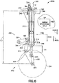
- Fig. 6 illustrates the landing gear 200A in a stowed position (e.g., inside the wheel well of the aircraft 100 ( Fig. 1 )) with the shock strut 210 substantially fully extended but retracted within the outer sleeve 310 to shorten a length of the landing gear 200A. It is noted that in each of Figs. 3-6 the shrink mechanism 300 is rotated 90 degrees relative to the rest of the landing gear 200A for clarity purposes only (e.g., so that the movement of the shrink mechanism can be illustrated). As can be seen in Fig.
- a coordinate system (e.g., "UP, Inbound” with the landing gear 200A in an un-stowed positon and "UP, Inboard” with the landing gear 200A in a stowed position) is illustrated for shrink mechanism 300 while the coordinate system (e.g., Up, Forward) is illustrated for the rest of the landing gear 200A.
- the shrink mechanism 300 preferably locks the shock strut 210 in an extended position relative to the outer sleeve 310 so that the outer cylinder 368 of the shock strut extends a distance X1 from the outer sleeve 310.
- the outer sleeve 310 is rotatably coupled to the wing 322 as described above ( Fig. 7 , Block 720) and the anchor arm 318 is coupled to the structure 320 of the wing 322 ( Fig. 7 , Block 730) as described above.
- the shrink mechanism 300 preferably forms an over-center lock that holds the shock strut 210 in the extended position relative to the outer sleeve 310.
- the shaft 312 and the outer sleeve 310 rotate relative to each other such that the shaft 312 is rotated relative to the outer sleeve 310 in direction RB.
- Relative rotation between the shaft 312 and the outer sleeve 310 preferably continues until a stop surface 324S of the shrink arm 324 contacts a corresponding stop surface 31 0S of the outer sleeve 310.
- a pivot axis AX7 at which the shrink arm 324 is rotatably coupled to the shrink link 326 is rotated passed a centerline OCL extending between the axis 314 and the pivot axis AX8 (about which the shrink link 326 is pivotally coupled to the outer cylinder 368).
- the inner cylinder 374 preferably moves in direction 400A causing the truck link 220 to rotate in direction RC.
- the static ride height position illustrated in Fig. 4 provides the landing gear 200A with a length L1 that, in turn, may provide available wheel 204 travel to absorb bumps, etc. during taxiing of the aircraft 100 ( Fig. 1 ).
- the inner cylinder 374 of the shock strut extends further in direction 400A relative to the outer cylinder 368 as shown in Fig. 5 .
- This further extension of the inner cylinder 374 causes rotation of the truck link 220 in direction RC to provide the landing gear with additional height X at take-off.
- the additional height X provides the landing gear with an extended length L2 at take-off.
- the shaft 312 rotates relative to the outer sleeve 310 in direction RA by virtue of the coupling between the shaft 312 and the structure 320 ( Fig. 2A ) of the wing 322 ( Fig. 2A ) provided by the rod 340.
- the relative rotation of the shaft 312 in direction RA preferably also causes the shrink arm 324 to rotate in direction RA.
- the rotation of the shrink arm 324 in direction RA moves the shrink link 326 in direction 400B within the outer sleeve 310 to retract the shock strut 210. Because the shrink link 326 is coupled to the outer cylinder 368 of the shock strut 210, the shock strut 210 also moves relative to the outer sleeve 310 in direction 400B ( Fig. 7 , Block 710) so that the shock strut 210 is retracted into the outer sleeve 310 by the distance X1.
- the retraction of the shock strut 210 into the outer sleeve 310 by the distance X1 preferably provides the landing gear 200A with a stowed length of L3 which is smaller than the length L2. It is noted that when the landing gear is stowed, the shock strut is substantially uncompressed. Moving the landing gear 200A from the stowed position 800 ( Fig. 8A ) to the un-stowed position 801 ( Fig. 8A ) occurs in substantially the reverse manner from that described above.
- the wings 322 create lift.
- the lift created by the wings 322 reduces the weight of the aircraft 100 applied to the landing gear 200A.
- the reduction in weight of the aircraft 100 applied to the landing gear 200A causes the shock strut 210 to extend or uncompress.
- Extension of the shock strut 210 preferably causes relative movement between an inner cylinder 374 ( Fig. 3 ) of the shock strut 210 and outer cylinder 368 of the shock strut 210.
- the relative movement of the inner cylinder 374 and outer cylinder 368 during extension of the shock strut 210 causes the truck lever 220 to rotate in direction RC ( Fig.
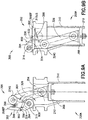
- a takeoff height position as seen best in Fig. 8B (see also Fig. 5 ), which may provide the aircraft 100 with additional height X relative to the static ride height A (see also Fig. 8A ) of the aircraft 100 (e.g., the ride height A is increased by height X at the takeoff height of the landing gear 200A).
- the additional height X which is preferably greater than the amount of extension provided by the shock strut 210 alone, provides for a predetermined angle of rotation ⁇ of the aircraft 100 relative to the ground GR, as seen in Fig. 7B , upon takeoff and provides for a predetermined angle of rotation ⁇ (e.g., angle of attack) of the aircraft 100 relative to ground GR upon landing.
- the angles of rotation ⁇ , ⁇ are preferably increased compared to takeoff and landing angles of rotation ⁇ ', ⁇ ' of the aircraft 100 when equipped with a conventional single axle landing gear CSS (see Figs. 1C and 8A - noting that in Fig.
- the conventional landing gear CSS and landing gear 200A are illustrated side by side for exemplary purposes only, otherwise the landing gear 200A and the conventional landing gear would be arranged along a common centerline CL relative to the airframe 100F centerline ACL) as seen in Fig. 7B where wheel travel is limited only by an amount of travel of the conventional shock strut CSS and the distance Z between a ground contact patch of the wheel(s) 204 and a tail skid pad 860 of the aircraft 100 remains the same for the aircraft 100.
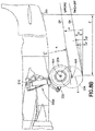
- the landing gear 200A can be coupled to the airframe 100F in substantially the same location as the conventional landing gear, and because the shock strut 210 is retractable into the outer sleeve 310, the landing gear 200A may fit within a conventional wheel well substantially without any modification to the aircraft 100 design. In other aspects, the landing gear may be retrofit to existing aircraft. For example, referring to Fig. 8A , a wheel retract path 820 for the conventional landing gear having shock strut CSS is illustrated compared to a wheel retract path 821 for the landing gear 200A. As can be seen in Fig.
- the wheel retract paths 820, 821 are preferably separated by a distance corresponding to the additional height X of the landing gear 200A when the landing gears are in an un-stowed position (such as during takeoff and landing), the wheel retract paths converse to a common path 850 within the wheel well allowing the landing gear 200A to fit within an existing wheel well.
- the landing gear 200A may provide the aircraft 100 with the same static ride height A as the conventional landing gear with shock strut CSS.
- the landing gear 200A may also include a hinged door 352 that is configured to engage and substantially seal a top of the opening 354 of the outer sleeve 310 with the landing gear 200A in the un-stowed position 801 ( Fig. 8A ).
- the hinged door 352 is preferably slaved with at least one linkage of the shrink mechanism 300 in any suitable manner.
- the hinged door 352 includes a first door portion 694 and a second door portion 396 that are pivotally coupled to each other with hinge 356.
- the first door portion 694 may be coupled to, for example, the shrink arm 324 so as to be spatially fixed with respect to the shrink arm 324.
- the coupling between the shrink arm 324 and the first door portion 394 is such that the shrink arm 324 and the first door portion 394 rotate as a single unit about the shaft rotation axis 314.
- the second door portion 396 preferably being hinged to the first door portion also rotates with the shrink arm 324 about the shaft rotation axis 314; however, as the shrink arm 324 rotates in direction 900 a free end 396EF of the second door portion 396 engages an upper surface 310US of the outer sleeve 310 adjacent the opening 354.
- the engagement between the free end 396EF preferably causes relative rotation between the first door portion 394 and the second door portion 396 so that the hinged door flattens to substantially form a seal with the upper surface 310US of the outer sleeve thereby substantially sealing the opening 354.
- the second door portion 396 is preferably biased relative to one or more of the first door portion 394 and the shrink arm 324 in any suitable manner, such as by any suitable biasing member.
- the biasing member 398 may be a tension spring that couples the second door portion 396 to the shrink arm 324 to bias the second door portion in direction 902.
- the biasing member 398 may be a torsion spring disposed at the hinge 356 to bias the second door portion in direction 902.
- the biasing member 398 also preferably causes the hinged door to fold on itself when the shrink arm 324 is rotated in direction 324, such as when shock strut 210 is retracted into the outer sleeve 310 during the landing gear 200A stowage.
- the biasing member 398 causes the second door portion 396 to rotate in direction 902 about the hinge 356 to fold the second door portion 396 relative to the first door portion 394.
- the folding of the hinged door 352 upon stowage reduces the amount of space occupied by the hinged door 352 so that, for example, the hinged door fits within existing wheel wells of the aircraft 100 ( Fig. 1 ) substantially without modification to the wheel well.
- solid lines, if any, connecting various elements and/or components may represent mechanical, electrical, fluid, optical, electromagnetic, wireless and other couplings and/or combinations thereof.
- "coupled” means associated directly as well as indirectly.
- a member A may be directly associated with a member B, or may be indirectly associated therewith, e.g., via another member C. It will be understood that not all relationships among the various disclosed elements are necessarily represented. Accordingly, couplings other than those depicted in the drawings may also exist.
- Dashed lines, if any, connecting blocks designating the various elements and/or components represent couplings similar in function and purpose to those represented by solid lines; however, couplings represented by the dashed lines may either be selectively provided or may relate to alternative examples of the present disclosure.
- elements and/or components, if any, represented with dashed lines indicate alternative examples of the present disclosure.
- One or more elements shown in solid and/or dashed lines may be omitted from a particular example without departing from the scope of the present disclosure.
- Environmental elements, if any, are represented with dotted lines. Virtual (imaginary) elements may also be shown for clarity.
- the blocks may represent operations and/or portions thereof and lines connecting the various blocks do not imply any particular order or dependency of the operations or portions thereof. Blocks represented by dashed lines indicate alternative operations and/or portions thereof. Dashed lines, if any, connecting the various blocks represent alternative dependencies of the operations or portions thereof. It will be understood that not all dependencies among the various disclosed operations are necessarily represented.
- Fig. 7 and the accompanying disclosure describing the operations of the method(s) set forth herein should not be interpreted as necessarily determining a sequence in which the operations are to be performed. Rather, although one illustrative order is indicated, it is to be understood that the sequence of the operations may be modified when appropriate. Accordingly, certain operations may be performed in a different order or simultaneously. Additionally, those skilled in the art will appreciate that not all operations described need be performed.
- first, second, etc. are used herein merely as labels, and are not intended to impose ordinal, positional, or hierarchical requirements on the items to which these terms refer. Moreover, reference to, e.g., a “second” item does not require or preclude the existence of, e.g., a "first” or lower-numbered item, and/or, e.g., a "third" or higher-numbered item.
- a system, apparatus, structure, article, element, component, or hardware “configured to” perform a specified function is indeed capable of performing the specified function without any alteration, rather than merely having potential to perform the specified function after further modification.
- the system, apparatus, structure, article, element, component, or hardware “configured to” perform a specified function is specifically selected, created, implemented, utilized, programmed, and/or designed for the purpose of performing the specified function.
- "configured to” denotes existing characteristics of a system, apparatus, structure, article, element, component, or hardware which enable the system, apparatus, structure, article, element, component, or hardware to perform the specified function without further modification.
- a system, apparatus, structure, article, element, component, or hardware described as being “configured to” perform a particular function may additionally or alternatively be described as being “adapted to” and/or as being “operative to” perform that function.
Landscapes
- Engineering & Computer Science (AREA)
- Mechanical Engineering (AREA)
- Aviation & Aerospace Engineering (AREA)
- Transmission Devices (AREA)
- Gear-Shifting Mechanisms (AREA)
- Vibration Dampers (AREA)
Applications Claiming Priority (1)
| Application Number | Priority Date | Filing Date | Title |
|---|---|---|---|
| US15/611,844 US10800516B2 (en) | 2017-06-02 | 2017-06-02 | Semi-levered shrink landing gear |
Publications (2)
| Publication Number | Publication Date |
|---|---|
| EP3409582A1 true EP3409582A1 (de) | 2018-12-05 |
| EP3409582B1 EP3409582B1 (de) | 2023-12-27 |
Family
ID=62217817
Family Applications (1)
| Application Number | Title | Priority Date | Filing Date |
|---|---|---|---|
| EP18173205.8A Active EP3409582B1 (de) | 2017-06-02 | 2018-05-18 | Halbgehebeltes schrumpffahrwerk |
Country Status (5)
| Country | Link |
|---|---|
| US (3) | US10800516B2 (de) |
| EP (1) | EP3409582B1 (de) |
| JP (1) | JP7120808B2 (de) |
| CN (1) | CN108974331B (de) |
| ES (1) | ES2974378T3 (de) |
Families Citing this family (16)
| Publication number | Priority date | Publication date | Assignee | Title |
|---|---|---|---|---|
| EP3263449B1 (de) * | 2016-07-01 | 2018-08-29 | Safran Landing Systems UK Limited | Fahrwerk für ein flugzeug |
| US10562614B2 (en) | 2016-09-21 | 2020-02-18 | The Boeing Company | Aircraft landing gear, aircraft, and related methods |
| US10384767B2 (en) | 2017-01-25 | 2019-08-20 | The Boeing Company | Single axle, semi-levered landing gear with shortening mechanism |
| US10597146B2 (en) * | 2017-02-28 | 2020-03-24 | The Boeing Company | Aircraft landing gear having a lever assembly, aircraft including the same, and related methods |
| US10766608B2 (en) * | 2017-02-28 | 2020-09-08 | The Boeing Company | Aircraft landing gear having a retract actuator, aircraft including the same, and related methods |
| US10669017B2 (en) | 2017-02-28 | 2020-06-02 | The Boeing Company | Aircraft landing gear, aircraft, and related methods |
| US10625849B2 (en) | 2017-04-11 | 2020-04-21 | The Boeing Company | Levered landing gear with inner shock strut |
| US10486798B2 (en) * | 2017-04-18 | 2019-11-26 | The Boeing Company | Aircraft landing gear assembly and method of assembling the same |
| US10800516B2 (en) | 2017-06-02 | 2020-10-13 | The Boeing Company | Semi-levered shrink landing gear |
| US10831193B2 (en) * | 2017-11-14 | 2020-11-10 | Sikorsky Aircraft Corporation | Enhanced taxi control for rigid rotors |
| US11161599B2 (en) | 2018-01-26 | 2021-11-02 | The Boeing Company | Landing gear strut assembly and method therefor |
| US10981646B2 (en) | 2018-07-30 | 2021-04-20 | The Boeing Company | Landing gear shrink link mechanism |
| US11192638B2 (en) * | 2019-10-31 | 2021-12-07 | Safran Landing Systems Canada Inc. | Aircraft landing gear acoustic shields |
| US11407500B2 (en) * | 2020-09-15 | 2022-08-09 | Safran Landing Systems Canada, Inc. | Landing gear with shortening motion |
| CN116101481B (zh) * | 2023-03-29 | 2025-07-25 | 西北工业大学 | 一种可三级收放的摇臂式起落架 |
| US12397905B1 (en) | 2024-06-24 | 2025-08-26 | American Honda Motor Co., Inc. | Locking system for aircraft landing gear bay doors |
Citations (8)
| Publication number | Priority date | Publication date | Assignee | Title |
|---|---|---|---|---|
| GB610698A (en) * | 1946-04-15 | 1948-10-19 | Fairey Aviat Co Ltd | Improvements in or relating to retractable undercarriages |
| US2754072A (en) * | 1952-09-23 | 1956-07-10 | Roeing Airplane Company | Aircraft landing gear |
| US2967682A (en) * | 1958-12-08 | 1961-01-10 | Jarry Hydraulics | Landing gear shortening mechanism |
| GB1216732A (en) * | 1967-05-29 | 1970-12-23 | Messier S | Retractable undercarriage for an aircraft |
| US4749152A (en) * | 1986-05-13 | 1988-06-07 | Messier-Hispano-Bugatti | Aircraft undercarriage of tilting-beam type and of reduced bulk |
| US5299761A (en) * | 1992-03-11 | 1994-04-05 | Messier-Bugatti | Raisable landing gear having a shortenable leg |
| US5429323A (en) * | 1992-12-28 | 1995-07-04 | Messier-Bugatti | Raisable undercarriage, in particular for a heavy transport aircraft |
| EP2489591A1 (de) * | 2011-02-21 | 2012-08-22 | The Boeing Company | Luft-Boden-Erkennungssystem für Flugzeugfahrwerk |
Family Cites Families (36)
| Publication number | Priority date | Publication date | Assignee | Title |
|---|---|---|---|---|
| GB484938A (en) | 1937-01-04 | 1938-05-12 | Aircraft Components Ltd | Improvements relating to breakable radius rod or like elements for retractable aircraft undercarriages |
| US2256540A (en) | 1940-02-15 | 1941-09-23 | Dowty Corp | Ski trimming lock |
| US2420066A (en) | 1941-08-22 | 1947-05-06 | Aeronautical & Mechanical Inve | Landing gear control and indicating arrangement |
| GB670889A (en) | 1949-11-10 | 1952-04-30 | Dowty Equipment Ltd | Improvements in aircraft alighting gear |
| US2933271A (en) | 1954-07-09 | 1960-04-19 | Menasco Mfg Company | Landing gear for helicopters |
| JPS5422679A (en) | 1977-07-19 | 1979-02-20 | Sugiyasu Kougiyou Kk | Continuous installing type parking lift |
| DE3406359A1 (de) | 1983-03-25 | 1984-09-27 | Messier-Hispano-Bugatti (S.A.), Montrouge | Frontfahrwerk fuer luftfahrzeug |
| FR2547271B1 (fr) * | 1983-06-08 | 1985-08-23 | Messier Hispano Sa | Atterrisseur du type a balancier |
| US5100083A (en) | 1990-02-13 | 1992-03-31 | The Boeing Company | Retractable landing gear with self-braced folding strut |
| FR2686857B1 (fr) * | 1992-02-04 | 1994-04-01 | Messier Bugatti | Amortisseur de jambe de train d'atterrissage d'aeronef. |
| JP3147539B2 (ja) | 1992-10-05 | 2001-03-19 | 本田技研工業株式会社 | 航空機の降着装置 |
| GB9223714D0 (en) | 1992-11-12 | 1992-12-23 | British Aerospace | Auxiliary control of aircraft landing gear movement |
| JPH08338045A (ja) | 1995-06-12 | 1996-12-24 | Kobelco Kenki Eng Kk | ステー装置 |
| EP0946564A1 (de) | 1996-11-19 | 1999-10-06 | Astra Aktiebolag | Neues verfahren zur herstellung von morphinanen |
| US6182925B1 (en) | 1999-03-30 | 2001-02-06 | The Boeing Company | Semi-levered landing gear and auxiliary strut therefor |
| WO2006094145A1 (en) | 2005-03-02 | 2006-09-08 | Goodrich Corporation | Landing gear with articulated length extension mechanism |
| GB0515359D0 (en) | 2005-07-26 | 2005-08-31 | Airbus Uk Ltd | Landing gear |
| GB2428650B (en) | 2005-08-04 | 2011-01-12 | Messier Dowty Ltd | Landing gear |
| GB2453554B (en) | 2007-10-09 | 2012-03-14 | Messier Dowty Ltd | Load detection in an aircraft landing gear |
| FR2922190B1 (fr) * | 2007-10-11 | 2010-04-09 | Eurocopter France | Verin de retraction, atterrisseur de giravion muni d'un tel verin de retraction |
| US8186620B2 (en) | 2008-06-25 | 2012-05-29 | Goodrich Corporation | Adjustable landing gear system |
| US8556209B2 (en) | 2008-10-22 | 2013-10-15 | Goodrich Corporation | Electric-powered transfer cylinder for landing gear system |
| US8087610B2 (en) | 2009-01-22 | 2012-01-03 | Goodrich Corporation | Aircraft shock strut having fixed upper bearing |
| GB2472988A (en) * | 2009-08-25 | 2011-03-02 | Messier Dowty Ltd | Main landing gear with rigid rear stay |
| US8448900B2 (en) * | 2010-03-24 | 2013-05-28 | The Boeing Company | Semi-levered landing gear and associated method |
| US9481452B2 (en) | 2010-11-22 | 2016-11-01 | The Boeing Company | Hydraulic actuator for semi levered landing gear |
| US8998133B2 (en) | 2011-04-01 | 2015-04-07 | The Boeing Company | Landing gear system |
| US8752785B2 (en) | 2012-06-25 | 2014-06-17 | Bell Helicopter Textron Inc. | Semi-levered articulated landing gear system |
| EP3213992B1 (de) | 2016-03-04 | 2018-04-25 | Safran Landing Systems UK Limited | Flugzeugfahrwerkanordnung |
| EP3263449B1 (de) | 2016-07-01 | 2018-08-29 | Safran Landing Systems UK Limited | Fahrwerk für ein flugzeug |
| US10259568B2 (en) | 2016-12-14 | 2019-04-16 | Goodrich Corporation | Non-jamming shrink latch assembly for retractable aircraft landing gear |
| US10384767B2 (en) | 2017-01-25 | 2019-08-20 | The Boeing Company | Single axle, semi-levered landing gear with shortening mechanism |
| US10766608B2 (en) | 2017-02-28 | 2020-09-08 | The Boeing Company | Aircraft landing gear having a retract actuator, aircraft including the same, and related methods |
| US10800516B2 (en) | 2017-06-02 | 2020-10-13 | The Boeing Company | Semi-levered shrink landing gear |
| US10933983B2 (en) | 2017-08-01 | 2021-03-02 | Safran Landing Systems Canada Inc. | Upper torque link central latch mechanism |
| US10974819B2 (en) | 2017-12-15 | 2021-04-13 | Goodrich Corporation | Latch assembly for shock strut |
-
2017
- 2017-06-02 US US15/611,844 patent/US10800516B2/en active Active
-
2018
- 2018-05-18 ES ES18173205T patent/ES2974378T3/es active Active
- 2018-05-18 EP EP18173205.8A patent/EP3409582B1/de active Active
- 2018-05-23 JP JP2018098651A patent/JP7120808B2/ja active Active
- 2018-06-01 CN CN201810553806.1A patent/CN108974331B/zh active Active
-
2020
- 2020-08-31 US US17/007,105 patent/US11572158B2/en active Active
-
2022
- 2022-11-17 US US18/056,336 patent/US11827342B2/en active Active
Patent Citations (8)
| Publication number | Priority date | Publication date | Assignee | Title |
|---|---|---|---|---|
| GB610698A (en) * | 1946-04-15 | 1948-10-19 | Fairey Aviat Co Ltd | Improvements in or relating to retractable undercarriages |
| US2754072A (en) * | 1952-09-23 | 1956-07-10 | Roeing Airplane Company | Aircraft landing gear |
| US2967682A (en) * | 1958-12-08 | 1961-01-10 | Jarry Hydraulics | Landing gear shortening mechanism |
| GB1216732A (en) * | 1967-05-29 | 1970-12-23 | Messier S | Retractable undercarriage for an aircraft |
| US4749152A (en) * | 1986-05-13 | 1988-06-07 | Messier-Hispano-Bugatti | Aircraft undercarriage of tilting-beam type and of reduced bulk |
| US5299761A (en) * | 1992-03-11 | 1994-04-05 | Messier-Bugatti | Raisable landing gear having a shortenable leg |
| US5429323A (en) * | 1992-12-28 | 1995-07-04 | Messier-Bugatti | Raisable undercarriage, in particular for a heavy transport aircraft |
| EP2489591A1 (de) * | 2011-02-21 | 2012-08-22 | The Boeing Company | Luft-Boden-Erkennungssystem für Flugzeugfahrwerk |
Also Published As
| Publication number | Publication date |
|---|---|
| JP2018203234A (ja) | 2018-12-27 |
| CN108974331B (zh) | 2023-05-30 |
| US20230070675A1 (en) | 2023-03-09 |
| JP7120808B2 (ja) | 2022-08-17 |
| US10800516B2 (en) | 2020-10-13 |
| EP3409582B1 (de) | 2023-12-27 |
| ES2974378T3 (es) | 2024-06-27 |
| US11827342B2 (en) | 2023-11-28 |
| CN108974331A (zh) | 2018-12-11 |
| US20200398974A1 (en) | 2020-12-24 |
| US11572158B2 (en) | 2023-02-07 |
| US20180346102A1 (en) | 2018-12-06 |
Similar Documents
| Publication | Publication Date | Title |
|---|---|---|
| US11827342B2 (en) | Semi-levered shrink landing gear | |
| US11136113B2 (en) | Single axle, semi-levered landing gear with shortening mechanism | |
| EP3366579B1 (de) | Flugzeugfahrwerk und zugehöriges verfahren | |
| EP3335988B1 (de) | Verklemmsichere schrumpfverriegelungsanordnung für einziehbares flugzeugfahrwerk | |
| EP3366578B1 (de) | Flugzeugfahrwerk und zugehörige verfahren | |
| US8505849B2 (en) | Device for retracting aircraft landing gear | |
| EP3366580B1 (de) | Flugzeugfahrwerk und zugehörige verfahren | |
| US11708151B2 (en) | Landing gear shrink link mechanism | |
| EP3388337B1 (de) | Ausgehebeltes fahrwerk mit innerem federbein | |
| US11014654B2 (en) | Pitch trimmer | |
| EP3498601B1 (de) | Verriegelungsanordnung für federbein | |
| CN114750933B (zh) | 一种不破坏飞机承载结构的小型化起落架收放机构 | |
| US11008091B2 (en) | Body mounted shrinking landing gear | |
| US20190233091A1 (en) | Landing gear strut assembly and method therefor | |
| EP3772459B1 (de) | Federbeinschrumpfsystem |
Legal Events
| Date | Code | Title | Description |
|---|---|---|---|
| PUAI | Public reference made under article 153(3) epc to a published international application that has entered the european phase |
Free format text: ORIGINAL CODE: 0009012 |
|
| STAA | Information on the status of an ep patent application or granted ep patent |
Free format text: STATUS: REQUEST FOR EXAMINATION WAS MADE |
|
| 17P | Request for examination filed |
Effective date: 20180518 |
|
| AK | Designated contracting states |
Kind code of ref document: A1 Designated state(s): AL AT BE BG CH CY CZ DE DK EE ES FI FR GB GR HR HU IE IS IT LI LT LU LV MC MK MT NL NO PL PT RO RS SE SI SK SM TR |
|
| AX | Request for extension of the european patent |
Extension state: BA ME |
|
| STAA | Information on the status of an ep patent application or granted ep patent |
Free format text: STATUS: EXAMINATION IS IN PROGRESS |
|
| 17Q | First examination report despatched |
Effective date: 20210318 |
|
| RAP3 | Party data changed (applicant data changed or rights of an application transferred) |
Owner name: THE BOEING COMPANY |
|
| REG | Reference to a national code |
Ref country code: DE Ref legal event code: R079 Free format text: PREVIOUS MAIN CLASS: B64C0025000000 Ipc: B64C0025040000 Ref document number: 602018063123 Country of ref document: DE |
|
| GRAP | Despatch of communication of intention to grant a patent |
Free format text: ORIGINAL CODE: EPIDOSNIGR1 |
|
| STAA | Information on the status of an ep patent application or granted ep patent |
Free format text: STATUS: GRANT OF PATENT IS INTENDED |
|
| RIC1 | Information provided on ipc code assigned before grant |
Ipc: B64C 25/34 20060101ALI20230606BHEP Ipc: B64C 25/14 20060101ALI20230606BHEP Ipc: B64C 25/04 20060101AFI20230606BHEP |
|
| INTG | Intention to grant announced |
Effective date: 20230711 |
|
| P01 | Opt-out of the competence of the unified patent court (upc) registered |
Effective date: 20230901 |
|
| GRAS | Grant fee paid |
Free format text: ORIGINAL CODE: EPIDOSNIGR3 |
|
| GRAA | (expected) grant |
Free format text: ORIGINAL CODE: 0009210 |
|
| STAA | Information on the status of an ep patent application or granted ep patent |
Free format text: STATUS: THE PATENT HAS BEEN GRANTED |
|
| AK | Designated contracting states |
Kind code of ref document: B1 Designated state(s): AL AT BE BG CH CY CZ DE DK EE ES FI FR GB GR HR HU IE IS IT LI LT LU LV MC MK MT NL NO PL PT RO RS SE SI SK SM TR |
|
| REG | Reference to a national code |
Ref country code: GB Ref legal event code: FG4D |
|
| REG | Reference to a national code |
Ref country code: CH Ref legal event code: EP |
|
| REG | Reference to a national code |
Ref country code: DE Ref legal event code: R096 Ref document number: 602018063123 Country of ref document: DE |
|
| REG | Reference to a national code |
Ref country code: IE Ref legal event code: FG4D |
|
| PG25 | Lapsed in a contracting state [announced via postgrant information from national office to epo] |
Ref country code: GR Free format text: LAPSE BECAUSE OF FAILURE TO SUBMIT A TRANSLATION OF THE DESCRIPTION OR TO PAY THE FEE WITHIN THE PRESCRIBED TIME-LIMIT Effective date: 20240328 |
|
| REG | Reference to a national code |
Ref country code: LT Ref legal event code: MG9D |
|
| PG25 | Lapsed in a contracting state [announced via postgrant information from national office to epo] |
Ref country code: LT Free format text: LAPSE BECAUSE OF FAILURE TO SUBMIT A TRANSLATION OF THE DESCRIPTION OR TO PAY THE FEE WITHIN THE PRESCRIBED TIME-LIMIT Effective date: 20231227 |
|
| PG25 | Lapsed in a contracting state [announced via postgrant information from national office to epo] |
Ref country code: LT Free format text: LAPSE BECAUSE OF FAILURE TO SUBMIT A TRANSLATION OF THE DESCRIPTION OR TO PAY THE FEE WITHIN THE PRESCRIBED TIME-LIMIT Effective date: 20231227 Ref country code: GR Free format text: LAPSE BECAUSE OF FAILURE TO SUBMIT A TRANSLATION OF THE DESCRIPTION OR TO PAY THE FEE WITHIN THE PRESCRIBED TIME-LIMIT Effective date: 20240328 Ref country code: FI Free format text: LAPSE BECAUSE OF FAILURE TO SUBMIT A TRANSLATION OF THE DESCRIPTION OR TO PAY THE FEE WITHIN THE PRESCRIBED TIME-LIMIT Effective date: 20231227 Ref country code: BG Free format text: LAPSE BECAUSE OF FAILURE TO SUBMIT A TRANSLATION OF THE DESCRIPTION OR TO PAY THE FEE WITHIN THE PRESCRIBED TIME-LIMIT Effective date: 20240327 |
|
| REG | Reference to a national code |
Ref country code: NL Ref legal event code: MP Effective date: 20231227 |
|
| REG | Reference to a national code |
Ref country code: AT Ref legal event code: MK05 Ref document number: 1644299 Country of ref document: AT Kind code of ref document: T Effective date: 20231227 |
|
| PG25 | Lapsed in a contracting state [announced via postgrant information from national office to epo] |
Ref country code: NL Free format text: LAPSE BECAUSE OF FAILURE TO SUBMIT A TRANSLATION OF THE DESCRIPTION OR TO PAY THE FEE WITHIN THE PRESCRIBED TIME-LIMIT Effective date: 20231227 |
|
| PG25 | Lapsed in a contracting state [announced via postgrant information from national office to epo] |
Ref country code: SE Free format text: LAPSE BECAUSE OF FAILURE TO SUBMIT A TRANSLATION OF THE DESCRIPTION OR TO PAY THE FEE WITHIN THE PRESCRIBED TIME-LIMIT Effective date: 20231227 Ref country code: RS Free format text: LAPSE BECAUSE OF FAILURE TO SUBMIT A TRANSLATION OF THE DESCRIPTION OR TO PAY THE FEE WITHIN THE PRESCRIBED TIME-LIMIT Effective date: 20231227 Ref country code: NO Free format text: LAPSE BECAUSE OF FAILURE TO SUBMIT A TRANSLATION OF THE DESCRIPTION OR TO PAY THE FEE WITHIN THE PRESCRIBED TIME-LIMIT Effective date: 20240327 Ref country code: NL Free format text: LAPSE BECAUSE OF FAILURE TO SUBMIT A TRANSLATION OF THE DESCRIPTION OR TO PAY THE FEE WITHIN THE PRESCRIBED TIME-LIMIT Effective date: 20231227 Ref country code: LV Free format text: LAPSE BECAUSE OF FAILURE TO SUBMIT A TRANSLATION OF THE DESCRIPTION OR TO PAY THE FEE WITHIN THE PRESCRIBED TIME-LIMIT Effective date: 20231227 Ref country code: HR Free format text: LAPSE BECAUSE OF FAILURE TO SUBMIT A TRANSLATION OF THE DESCRIPTION OR TO PAY THE FEE WITHIN THE PRESCRIBED TIME-LIMIT Effective date: 20231227 |
|
| REG | Reference to a national code |
Ref country code: ES Ref legal event code: FG2A Ref document number: 2974378 Country of ref document: ES Kind code of ref document: T3 Effective date: 20240627 |
|
| PG25 | Lapsed in a contracting state [announced via postgrant information from national office to epo] |
Ref country code: IS Free format text: LAPSE BECAUSE OF FAILURE TO SUBMIT A TRANSLATION OF THE DESCRIPTION OR TO PAY THE FEE WITHIN THE PRESCRIBED TIME-LIMIT Effective date: 20240427 |
|
| PG25 | Lapsed in a contracting state [announced via postgrant information from national office to epo] |
Ref country code: AT Free format text: LAPSE BECAUSE OF FAILURE TO SUBMIT A TRANSLATION OF THE DESCRIPTION OR TO PAY THE FEE WITHIN THE PRESCRIBED TIME-LIMIT Effective date: 20231227 Ref country code: CZ Free format text: LAPSE BECAUSE OF FAILURE TO SUBMIT A TRANSLATION OF THE DESCRIPTION OR TO PAY THE FEE WITHIN THE PRESCRIBED TIME-LIMIT Effective date: 20231227 |
|
| PG25 | Lapsed in a contracting state [announced via postgrant information from national office to epo] |
Ref country code: SK Free format text: LAPSE BECAUSE OF FAILURE TO SUBMIT A TRANSLATION OF THE DESCRIPTION OR TO PAY THE FEE WITHIN THE PRESCRIBED TIME-LIMIT Effective date: 20231227 |
|
| PG25 | Lapsed in a contracting state [announced via postgrant information from national office to epo] |
Ref country code: SM Free format text: LAPSE BECAUSE OF FAILURE TO SUBMIT A TRANSLATION OF THE DESCRIPTION OR TO PAY THE FEE WITHIN THE PRESCRIBED TIME-LIMIT Effective date: 20231227 Ref country code: SK Free format text: LAPSE BECAUSE OF FAILURE TO SUBMIT A TRANSLATION OF THE DESCRIPTION OR TO PAY THE FEE WITHIN THE PRESCRIBED TIME-LIMIT Effective date: 20231227 Ref country code: RO Free format text: LAPSE BECAUSE OF FAILURE TO SUBMIT A TRANSLATION OF THE DESCRIPTION OR TO PAY THE FEE WITHIN THE PRESCRIBED TIME-LIMIT Effective date: 20231227 Ref country code: IS Free format text: LAPSE BECAUSE OF FAILURE TO SUBMIT A TRANSLATION OF THE DESCRIPTION OR TO PAY THE FEE WITHIN THE PRESCRIBED TIME-LIMIT Effective date: 20240427 Ref country code: EE Free format text: LAPSE BECAUSE OF FAILURE TO SUBMIT A TRANSLATION OF THE DESCRIPTION OR TO PAY THE FEE WITHIN THE PRESCRIBED TIME-LIMIT Effective date: 20231227 Ref country code: CZ Free format text: LAPSE BECAUSE OF FAILURE TO SUBMIT A TRANSLATION OF THE DESCRIPTION OR TO PAY THE FEE WITHIN THE PRESCRIBED TIME-LIMIT Effective date: 20231227 Ref country code: AT Free format text: LAPSE BECAUSE OF FAILURE TO SUBMIT A TRANSLATION OF THE DESCRIPTION OR TO PAY THE FEE WITHIN THE PRESCRIBED TIME-LIMIT Effective date: 20231227 |
|
| PG25 | Lapsed in a contracting state [announced via postgrant information from national office to epo] |
Ref country code: PL Free format text: LAPSE BECAUSE OF FAILURE TO SUBMIT A TRANSLATION OF THE DESCRIPTION OR TO PAY THE FEE WITHIN THE PRESCRIBED TIME-LIMIT Effective date: 20231227 Ref country code: PT Free format text: LAPSE BECAUSE OF FAILURE TO SUBMIT A TRANSLATION OF THE DESCRIPTION OR TO PAY THE FEE WITHIN THE PRESCRIBED TIME-LIMIT Effective date: 20240429 |
|
| PG25 | Lapsed in a contracting state [announced via postgrant information from national office to epo] |
Ref country code: PT Free format text: LAPSE BECAUSE OF FAILURE TO SUBMIT A TRANSLATION OF THE DESCRIPTION OR TO PAY THE FEE WITHIN THE PRESCRIBED TIME-LIMIT Effective date: 20240429 Ref country code: PL Free format text: LAPSE BECAUSE OF FAILURE TO SUBMIT A TRANSLATION OF THE DESCRIPTION OR TO PAY THE FEE WITHIN THE PRESCRIBED TIME-LIMIT Effective date: 20231227 |
|
| REG | Reference to a national code |
Ref country code: DE Ref legal event code: R097 Ref document number: 602018063123 Country of ref document: DE |
|
| PG25 | Lapsed in a contracting state [announced via postgrant information from national office to epo] |
Ref country code: DK Free format text: LAPSE BECAUSE OF FAILURE TO SUBMIT A TRANSLATION OF THE DESCRIPTION OR TO PAY THE FEE WITHIN THE PRESCRIBED TIME-LIMIT Effective date: 20231227 |
|
| PG25 | Lapsed in a contracting state [announced via postgrant information from national office to epo] |
Ref country code: DK Free format text: LAPSE BECAUSE OF FAILURE TO SUBMIT A TRANSLATION OF THE DESCRIPTION OR TO PAY THE FEE WITHIN THE PRESCRIBED TIME-LIMIT Effective date: 20231227 |
|
| PLBE | No opposition filed within time limit |
Free format text: ORIGINAL CODE: 0009261 |
|
| STAA | Information on the status of an ep patent application or granted ep patent |
Free format text: STATUS: NO OPPOSITION FILED WITHIN TIME LIMIT |
|
| 26N | No opposition filed |
Effective date: 20240930 |
|
| REG | Reference to a national code |
Ref country code: CH Ref legal event code: PL |
|
| PG25 | Lapsed in a contracting state [announced via postgrant information from national office to epo] |
Ref country code: MC Free format text: LAPSE BECAUSE OF FAILURE TO SUBMIT A TRANSLATION OF THE DESCRIPTION OR TO PAY THE FEE WITHIN THE PRESCRIBED TIME-LIMIT Effective date: 20231227 |
|
| PG25 | Lapsed in a contracting state [announced via postgrant information from national office to epo] |
Ref country code: LU Free format text: LAPSE BECAUSE OF NON-PAYMENT OF DUE FEES Effective date: 20240518 |
|
| PG25 | Lapsed in a contracting state [announced via postgrant information from national office to epo] |
Ref country code: MC Free format text: LAPSE BECAUSE OF FAILURE TO SUBMIT A TRANSLATION OF THE DESCRIPTION OR TO PAY THE FEE WITHIN THE PRESCRIBED TIME-LIMIT Effective date: 20231227 Ref country code: LU Free format text: LAPSE BECAUSE OF NON-PAYMENT OF DUE FEES Effective date: 20240518 Ref country code: CH Free format text: LAPSE BECAUSE OF NON-PAYMENT OF DUE FEES Effective date: 20240531 |
|
| REG | Reference to a national code |
Ref country code: BE Ref legal event code: MM Effective date: 20240531 |
|
| PG25 | Lapsed in a contracting state [announced via postgrant information from national office to epo] |
Ref country code: IE Free format text: LAPSE BECAUSE OF NON-PAYMENT OF DUE FEES Effective date: 20240518 |
|
| PG25 | Lapsed in a contracting state [announced via postgrant information from national office to epo] |
Ref country code: SI Free format text: LAPSE BECAUSE OF FAILURE TO SUBMIT A TRANSLATION OF THE DESCRIPTION OR TO PAY THE FEE WITHIN THE PRESCRIBED TIME-LIMIT Effective date: 20231227 Ref country code: BE Free format text: LAPSE BECAUSE OF NON-PAYMENT OF DUE FEES Effective date: 20240531 |
|
| PGFP | Annual fee paid to national office [announced via postgrant information from national office to epo] |
Ref country code: DE Payment date: 20250529 Year of fee payment: 8 |
|
| PGFP | Annual fee paid to national office [announced via postgrant information from national office to epo] |
Ref country code: GB Payment date: 20250527 Year of fee payment: 8 Ref country code: ES Payment date: 20250602 Year of fee payment: 8 |
|
| PGFP | Annual fee paid to national office [announced via postgrant information from national office to epo] |
Ref country code: IT Payment date: 20250521 Year of fee payment: 8 |
|
| PGFP | Annual fee paid to national office [announced via postgrant information from national office to epo] |
Ref country code: FR Payment date: 20250526 Year of fee payment: 8 |
|
| PG25 | Lapsed in a contracting state [announced via postgrant information from national office to epo] |
Ref country code: CY Free format text: LAPSE BECAUSE OF FAILURE TO SUBMIT A TRANSLATION OF THE DESCRIPTION OR TO PAY THE FEE WITHIN THE PRESCRIBED TIME-LIMIT; INVALID AB INITIO Effective date: 20180518 |
|
| PG25 | Lapsed in a contracting state [announced via postgrant information from national office to epo] |
Ref country code: HU Free format text: LAPSE BECAUSE OF FAILURE TO SUBMIT A TRANSLATION OF THE DESCRIPTION OR TO PAY THE FEE WITHIN THE PRESCRIBED TIME-LIMIT; INVALID AB INITIO Effective date: 20180518 |