EP3410037A1 - Kühleinheit, kühlsystem und verfahren zur steuerung eines kühlkreislaufs - Google Patents
Kühleinheit, kühlsystem und verfahren zur steuerung eines kühlkreislaufs Download PDFInfo
- Publication number
- EP3410037A1 EP3410037A1 EP18175305.4A EP18175305A EP3410037A1 EP 3410037 A1 EP3410037 A1 EP 3410037A1 EP 18175305 A EP18175305 A EP 18175305A EP 3410037 A1 EP3410037 A1 EP 3410037A1
- Authority
- EP
- European Patent Office
- Prior art keywords
- refrigerant
- bypass
- compressor
- refrigerating machine
- machine oil
- Prior art date
- Legal status (The legal status is an assumption and is not a legal conclusion. Google has not performed a legal analysis and makes no representation as to the accuracy of the status listed.)
- Withdrawn
Links
Images

Classifications
-
- F—MECHANICAL ENGINEERING; LIGHTING; HEATING; WEAPONS; BLASTING
- F25—REFRIGERATION OR COOLING; COMBINED HEATING AND REFRIGERATION SYSTEMS; HEAT PUMP SYSTEMS; MANUFACTURE OR STORAGE OF ICE; LIQUEFACTION SOLIDIFICATION OF GASES
- F25B—REFRIGERATION MACHINES, PLANTS OR SYSTEMS; COMBINED HEATING AND REFRIGERATION SYSTEMS; HEAT PUMP SYSTEMS
- F25B31/00—Compressor arrangements
- F25B31/002—Lubrication
- F25B31/004—Lubrication oil recirculating arrangements
-
- F—MECHANICAL ENGINEERING; LIGHTING; HEATING; WEAPONS; BLASTING
- F25—REFRIGERATION OR COOLING; COMBINED HEATING AND REFRIGERATION SYSTEMS; HEAT PUMP SYSTEMS; MANUFACTURE OR STORAGE OF ICE; LIQUEFACTION SOLIDIFICATION OF GASES
- F25B—REFRIGERATION MACHINES, PLANTS OR SYSTEMS; COMBINED HEATING AND REFRIGERATION SYSTEMS; HEAT PUMP SYSTEMS
- F25B43/00—Arrangements for separating or purifying gases or liquids; Arrangements for vaporising the residuum of liquid refrigerant, e.g. by heat
- F25B43/02—Arrangements for separating or purifying gases or liquids; Arrangements for vaporising the residuum of liquid refrigerant, e.g. by heat for separating lubricants from the refrigerant
-
- F—MECHANICAL ENGINEERING; LIGHTING; HEATING; WEAPONS; BLASTING
- F25—REFRIGERATION OR COOLING; COMBINED HEATING AND REFRIGERATION SYSTEMS; HEAT PUMP SYSTEMS; MANUFACTURE OR STORAGE OF ICE; LIQUEFACTION SOLIDIFICATION OF GASES
- F25B—REFRIGERATION MACHINES, PLANTS OR SYSTEMS; COMBINED HEATING AND REFRIGERATION SYSTEMS; HEAT PUMP SYSTEMS
- F25B2400/00—Component parts or details not otherwise provided for in this subclass
- F25B2400/04—Refrigeration circuit bypassing means
- F25B2400/0409—Refrigeration circuit bypassing means for evaporators
-
- F—MECHANICAL ENGINEERING; LIGHTING; HEATING; WEAPONS; BLASTING
- F25—REFRIGERATION OR COOLING; COMBINED HEATING AND REFRIGERATION SYSTEMS; HEAT PUMP SYSTEMS; MANUFACTURE OR STORAGE OF ICE; LIQUEFACTION SOLIDIFICATION OF GASES
- F25B—REFRIGERATION MACHINES, PLANTS OR SYSTEMS; COMBINED HEATING AND REFRIGERATION SYSTEMS; HEAT PUMP SYSTEMS
- F25B2400/00—Component parts or details not otherwise provided for in this subclass
- F25B2400/04—Refrigeration circuit bypassing means
- F25B2400/0411—Refrigeration circuit bypassing means for expansion valves or capillary tubes
-
- F—MECHANICAL ENGINEERING; LIGHTING; HEATING; WEAPONS; BLASTING
- F25—REFRIGERATION OR COOLING; COMBINED HEATING AND REFRIGERATION SYSTEMS; HEAT PUMP SYSTEMS; MANUFACTURE OR STORAGE OF ICE; LIQUEFACTION SOLIDIFICATION OF GASES
- F25B—REFRIGERATION MACHINES, PLANTS OR SYSTEMS; COMBINED HEATING AND REFRIGERATION SYSTEMS; HEAT PUMP SYSTEMS
- F25B2700/00—Sensing or detecting of parameters; Sensors therefor
- F25B2700/21—Temperatures
- F25B2700/2113—Temperatures of a suction accumulator
Definitions
- the present invention relates to a refrigeration unit configuring a refrigeration cycle, a refrigeration system including the refrigeration unit, and a method of controlling a refrigerant circuit.
- a refrigeration system such as a freezer and an air conditioner includes a heat source-side unit that includes a compressor and a condenser, and a heat utilization-side unit (such as freezer case and indoor air conditioner) that includes an evaporator.
- the heat source-side unit (hereinafter, refrigeration unit) often includes a gas-liquid separator that separates a liquid refrigerant from the refrigerant to be sucked into the compressor in order to protect the compressor from liquid compression (e.g., JP 2010-210208 A and JP H5-79357 U ).
- a gas-liquid separator that separates a liquid refrigerant from the refrigerant to be sucked into the compressor in order to protect the compressor from liquid compression (e.g., JP 2010-210208 A and JP H5-79357 U ).
- JP 2010-210208 A to avoid deterioration of lubricity due to viscosity increase of refrigerating machine oil inside the compressor, a heater is provided on a casing of the compressor to prevent viscosity increase of the refrigerating machine oil.
- the refrigerating machine oil used for lubrication of a sliding part of the compressor flows out to the heat utilization-side unit together with the refrigerant discharged from the compressor.
- the refrigerating machine oil that is accumulated, in a state of being dissolved in the liquid refrigerant, on a bottom inside the gas-liquid separator is sucked and recovered by an oil returning mechanism such as a U-shaped tube with a pickup hole and a capillary tube.
- the sucked refrigerating machine oil is returned to the compressor.
- JP H5-79357 U in a case where discharge temperature of the refrigerant discharged from the compressor or suction temperature or a degree of superheat of the refrigerant to be sucked into the compressor becomes equal to or higher than a set value, a part of the liquid refrigerant condensed and liquefied by the condenser is sucked, together with gas refrigerant passed through the evaporator, into the compressor through the gas-liquid separator, which suppresses temperature increase of the gas refrigerant to be sucked into the compressor.
- Prescribed refrigerant evaporation temperature is given to the refrigeration unit and the refrigeration system. Evaporation temperature is settable within a range of the prescribed evaporation temperature.
- the evaporation temperature set according to the purpose of use of the refrigeration system and air temperature is such a low temperature that largely influences the viscosity of the refrigerating machine oil
- the viscosity of the refrigerating machine oil that is accumulated, in a state of being dissolved in the liquid refrigerant, in the gas-liquid separator is increased, and suction of the refrigerating machine oil to the oil returning mechanism provided in the gas-liquid separator slows down. This deteriorates the return of the refrigerating machine oil from the gas-liquid separator to the compressor.
- a hole diameter of the oil returning mechanism is designed such that a dilution rate of the refrigerating machine oil by the liquid refrigerant in the compressor becomes equal to or lower than an appropriate value at which lubricity is secured. If the hole diameter of the oil returning mechanism is increased in order to improve an oil returning property when the evaporation temperature is set to a low temperature at which the viscosity of the refrigerating machine oil is increased, the refrigerating machine oil is excessively returned, together with the liquid refrigerant, to the compressor when the viscosity is normal.
- the heater may be used to heat the gas-liquid separator, thereby preventing viscosity increase of the refrigerating machine oil. Additional installation of the heater, however, increases its manufacturing cost and running cost.
- JP H5-79357 U described above relates to a phenomenon in which the refrigerating machine oil accumulated in the gas-liquid separator is not conveyed by the gas refrigerant to the compressor because the refrigerating machine oil is difficult to dissolve in the gas refrigerant when the temperature of the gas refrigerant to be sucked into the compressor is increased.
- JP H5-79357 U described above does not deal with the viscosity increase of the refrigerating machine oil when the evaporation temperature is set to a low temperature.
- an object of the present invention is to avoid deterioration of an oil returning property to the compressor due to viscosity increase of the refrigerating machine oil accumulated in the gas-liquid separator.
- a refrigeration unit includes a refrigerant circuit including a compressor, a heat exchanger, and a decompression section and supplies, to a heat use destination, a refrigerant passed through the decompression section.
- the compressor compresses the refrigerant
- the heat exchanger exchanges heat of the refrigerant with air
- the decompression section decompresses the refrigerant.
- the refrigeration unit includes a gas-liquid separator interposed between the heat use destination and the compressor, a bypass route configured to cause at least a part of the refrigerant flowing toward the decompression section through the heat exchanger, to flow into the gas-liquid separator, a bypass valve configured to open or close the bypass route, or to regulate a flow rate of the refrigerant flowing through the bypass route, and a control section configured to control the bypass valve.
- the gas-liquid separator includes an oil returning mechanism that recovers refrigerating machine oil accumulated inside in a state of being dissolved in a liquid phase of the refrigerant and returns the recovered refrigerating machine oil to the compressor.
- Two-layer separation temperature on a low-temperature side of a mixed solution of the liquid phase of the refrigerant and the refrigerating machine oil is lower than a lower limit of prescribed evaporation temperature determined for the refrigeration unit.
- the control section is configured to control the bypass valve based on a predetermined condition under which deterioration of an oil returning property due to viscosity increase of the refrigerating machine oil is expected, to take bypass measures of opening the bypass route or increasing the flow rate of the refrigerant flowing through the bypass route.
- an index used for the condition is preferably saturation temperature corresponding to pressure of the refrigerant that is sucked into the compressor, and the control section is preferably configured to control the bypass valve to take the bypass measures in a case where the saturation temperature is lower than a prescribed value.
- control section is preferably configured to intermittently take the bypass measures every predetermined time based on the condition.
- control section is preferably configured to take the bypass measures in a case where saturation temperature corresponding to pressure of the refrigerant that is sucked into the compressor is lower than a prescribed value and a liquid level of the refrigerating machine oil in the compressor is lower than a prescribed liquid level.
- control section is preferably configured to control the bypass valve to terminate the bypass measures when a prescribed time elapses after the start of the bypass measures, or when the liquid level of the refrigerating machine oil in the compressor reaches at least the prescribed liquid level by the bypass measures.
- control section is preferably configured to take the bypass measures in a case where saturation temperature corresponding to pressure of the refrigerant that is sucked into the compressor is lower than a prescribed value and a degree of superheat of the refrigerating machine oil in the compressor is higher than a prescribed degree of superheat.
- control section is preferably configured to control the bypass valve to terminate the bypass measures when a prescribed time elapses after the start of the bypass measures, or when a degree of superheat of the refrigerating machine oil in the compressor is suppressed to at least a prescribed degree of superheat by the bypass measures.
- a refrigeration system includes a compressor compressing a refrigerant, a heat exchanger exchanging heat of the refrigerant with air, a decompression section decompressing the refrigerant, and an evaporator evaporating the refrigerant.
- the refrigeration system includes a gas-liquid separator interposed between the evaporator and the compressor, a bypass route configured to cause at least a part of the refrigerant flowing toward the decompression section through the heat exchanger, to flow into the gas-liquid separator, a bypass valve configured to open or close the bypass route, or to regulate a flow rate of the refrigerant flowing through the bypass route, and a control section configured to control the bypass valve.
- the gas-liquid separator includes an oil returning mechanism that recovers refrigerating machine oil accumulated inside in a state of being dissolved in a liquid phase of the refrigerant and returns the recovered refrigerating machine oil to the compressor.
- Two-layer separation temperature on a low-temperature side of a mixed solution of the liquid phase of the refrigerant and the refrigerating machine oil is lower than a lower limit of prescribed evaporation temperature determined for the refrigeration system.
- the control section is configured to control the bypass valve based on a predetermined condition under which deterioration of an oil returning property due to viscosity increase of the refrigerating machine oil is expected, to take bypass measures of opening the bypass route or increasing the flow rate of the refrigerant flowing through the bypass route.
- a method of controlling a refrigerant circuit that includes a compressor compressing a refrigerant, a heat exchanger exchanging heat of the refrigerant with air, and a decompression section decompressing the refrigerant.
- the refrigerant circuit includes a gas-liquid separator, a bypass route, and a bypass valve.
- the gas-liquid separator is interposed between a heat use destination to which the refrigerant passed through the decompression section is supplied and the compressor.
- the bypass route causes at least a part of the refrigerant flowing toward the decompression section through the heat exchanger, to flow into the gas-liquid separator.
- the bypass valve opens or closes the bypass route, or regulates a flow rate of the refrigerant flowing through the bypass route.
- the method includes controlling the bypass vale to open the bypass route or to increase the flow rate of the refrigerant flowing through the bypass route, based on a predetermined condition under which deterioration of an oil returning property due to viscosity increase of refrigerating machine oil is expected, and causing an oil returning mechanism provided in the gas-liquid separator to recover the refrigerating machine oil accumulated, in a state of being dissolved in a liquid phase of the refrigerant, inside the gas-liquid separator, and to return the recovered refrigerating machine oil to the compressor.
- an appropriate amount of liquid phase of the refrigerant is mixed, through the bypass route, to the refrigerating machine oil accumulated in the gas-liquid separator at a suitable time, based on the condition under which deterioration of the oil returning property due to viscosity increase of the refrigerating machine oil in the gas-liquid separator is expected. Accordingly, viscosity increase of the entire mixed solution of the refrigerating machine oil accumulated in the gas-liquid separator and the liquid refrigerant is suppressed even at a low temperature.
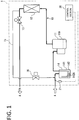
- a refrigeration unit 1 (condensing unit) illustrated in FIG. 1 includes a heat source circuit 10, a gas-liquid separator 14, a bypass route 15, a bypass valve 16, and a control section 20.
- the heat source circuit 10 includes a compressor 11, a heat exchanger 12, and a decompression section 13.
- a housing that houses the components 11 to 13 of the heat source circuit 10, the gas-liquid separator 14, the bypass route 15, and the bypass valve 16 is disposed outdoors.
- the refrigeration unit 1 exchanges, by the heat exchanger 12, heat of a refrigerant compressed by the compressor 11 with air as a heat source, then decompresses the refrigerant by the decompression section 13 such as an expansion valve, and supplies the refrigerant passed through the decompression section 13, to a heat use destination A disposed indoors.
- the heat use destination A includes an unillustrated evaporator that configures a refrigeration cycle, together with the heat source circuit 10 of the refrigeration unit 1.
- the refrigeration system includes an unillustrated heat use destination unit provided with the evaporator, the refrigeration unit 1, and piping that connects the heat use destination unit and the refrigeration unit 1.
- the heat use destination unit corresponds to, for example, a refrigerator case and a freezer case that are installed in a store and house foods.
- Prescribed refrigerant evaporation temperature is given to the refrigeration unit 1.
- Evaporation temperature is settable within a range of the prescribed evaporation temperature.
- An appropriate refrigerant for example, an HFC refrigerant such as R404A, and a natural refrigerant such as CO 2 are usable for the refrigeration system according to the present embodiment.
- the refrigeration system according to the present embodiment is applicable to any of a subcritical cycle and a transcritical cycle.
- the heat exchanger 12 functions as a condenser that condenses and liquefies an inflow gas refrigerant through heat exchange with the air, in the subcritical cycle.
- the heat exchanger 12 functions as a gas cooler that cools an inflow refrigerant in a supercritical state through heat exchange with the air.
- Refrigerating machine oil is sealed in a housing 11A of the compressor 11 in order to lubricate a sliding part such as a bearing of a built-in compression mechanism.
- oil having compatibility with the refrigerant used in the refrigeration system according to the present embodiment is appropriately selectable.
- ester synthetic oil is selectable for CO 2 .
- examples of the selectable ester synthetic oil include "diamond freeze MA68" that is a product available from JXTG Nippon Oil & Energy Corporation.
- R404A that is one kind of HFC refrigerant
- "diamond freeze MA32R” that is a product available from JXTG Nippon Oil & Energy Corporation is selectable.
- the refrigerating machine oil dissolves in the refrigerant. Therefore, the refrigerating machine oil is discharged together with the refrigerant from the compressor 11, and flows out to the heat use destination A through the heat exchanger 12 and the decompression section 13.
- the present embodiment includes main features in the configuration of the refrigerant circuit that includes the heat source circuit 10, the gas-liquid separator 14, the bypass route 15, and the bypass valve 16, and in a method of controlling the refrigerant circuit by the control section 20.
- the refrigerant to be sucked into the compressor 11 is received by the gas-liquid separator 14 interposed between the heat use destination A and the compressor 11 and is separated into a gas refrigerant and a liquid refrigerant in order to protect the compressor 11 from liquid compression.
- the gas-liquid separator 14 includes a tank 141 and an oil returning mechanism 142.
- the tank 141 receives the refrigerant returned from the heat use destination A.
- the oil returning mechanism 142 recovers the refrigerating machine oil that is accumulated, in a state of being dissolved with the liquid refrigerant, on a bottom inside the tank 141 and returns the recovered refrigerating machine oil to the compressor 11.
- the oil returning mechanism 142 includes, for example, a U-shaped tube with a pickup hole 142A (small hole) or a capillary tube.
- the refrigerating machine oil accumulated inside the tank 141 is sucked by the oil returning mechanism 142, and is sucked together with the gas refrigerant into the compressor 11 to be returned to the inside of the housing 11A of the compressor 11.
- the refrigerating machine oil is accumulated, in the state of being dissolved in the liquid refrigerant, also in the housing 11A of the compressor 11.
- a hole diameter of the oil returning mechanism 142 is designed such that a dilution rate of the refrigerating machine oil by the liquid refrigerant in the compressor 11 becomes equal to or lower than an appropriate value at which lubricity is secured.
- the refrigerating machine oil is increased in viscosity due to temperature decrease. Accordingly, if the refrigerant evaporation temperature is such a low temperature that largely influences the viscosity of the refrigerating machine oil, deterioration of an oil returning property of the refrigerating machine oil accumulated in the gas-liquid separator 14, to the compressor 11 is expected.
- the evaporation temperature corresponds to outlet temperature of the evaporator in the heat use destination unit.
- the evaporation temperature of the refrigeration unit 1 is determined in a range of, for example, -5°C to -45°C. This temperature range is referred to as the prescribed evaporation temperature.
- the optional evaporation temperature is settable within the range of the prescribed evaporation temperature by the user according to use application of the refrigeration system including the refrigeration unit 1, air temperature, etc.
- the evaporation temperature set by the user is referred to as set evaporation temperature.
- the refrigeration unit 1 mixes the liquid refrigerant to the gas-liquid separator 14 through the bypass route 15 at a suitable time, thereby suppressing viscosity increase of a mixed solution of the refrigerating machine oil accumulated in the gas-liquid separator 14 and the liquid refrigerant.
- the refrigeration unit 1 includes the bypass route 15 that causes a part of the refrigerant passed through the heat exchanger 12 to flow into the gas-liquid separator 14 and the bypass valve 16 that opens or closes the bypass route 15, as well as controls, by the control section 20, the bypass valve 16 based on a predetermined condition under which deterioration of the oil returning property due to viscosity increase of the refrigerating machine oil in the gas-liquid separator 14 is expected.
- a pressure sensor 21 that detects pressure of the refrigerant sucked into the compressor 11 is used in the present embodiment.
- the suction pressure saturation temperature varies according to the set evaporation temperature.
- the bypass route 15 includes piping that connects an outlet side of the heat exchanger 12 and an inlet side of the gas-liquid separator 14, and a fitting, etc.
- the bypass valve 16 is a solenoid valve that is driven in response to an instruction issued from the control section 20 to open or close the bypass route 15.
- the bypass route 15 is opened by the bypass valve 16, a part of the refrigerant that flows toward the decompression section 13 through the heat exchanger 12, flows into the gas-liquid separator 14 through the bypass route 15.
- the refrigerant that has flowed through the bypass route 15 and reached the gas-liquid separator 14 is decompressed into a gas-liquid two-phase state.
- the refrigerant that has passed through the evaporator of the heat use destination A and the refrigerant that has flowed through the bypass route 15 flow into the gas-liquid separator 14.
- the refrigerant that has flowed into the tank 141 of the gas-liquid separator 14 is separated into gas phase and liquid phase due to density difference, and the liquid phase having density larger than density of the gas phase is accumulated on the bottom of the tank 141.
- the refrigerating machine oil in the state of being dissolved in the refrigerant is also conveyed through the refrigerant circuit together with the refrigerant. Therefore, the refrigerating machine oil included in each of the refrigerant from the heat use destination A and the refrigerant from the bypass route 15 also flows into the gas-liquid separator 14, and is accumulated on the bottom of the tank 141. The refrigerating machine oil is mixed with the liquid refrigerant on the bottom of the tank 141 and dissolves in the liquid refrigerant.
- the refrigerant that has flowed through the bypass route 15 is merged with the refrigerant that flows toward the gas-liquid separator 14 from the heat use destination A, and the merged refrigerant flows into the gas-liquid separator 14.
- the configuration is not limited thereto, and the refrigerant that has flowed through the bypass route 15 may not be merged with the flow of the refrigerant from the heat use destination A, and may directly flow into the gas-liquid separator 14.
- control section 20 transmits, to the bypass valve 16, an instruction to open the bypass route 15, thereby opening the bypass route 15.
- bypass measures are started.
- control section 20 uses suction pressure detected by the pressure sensor 21, to calculate saturation temperature corresponding to the suction pressure. In a case where the suction pressure saturation temperature in the gas-liquid separator 14 is lower than the prescribed value, the control section 20 transmits the instruction to the bypass valve 16 to open the bypass route 15, and causes the refrigerant to flow into the gas-liquid separator 14 through the bypass route 15 because deterioration of the oil returning property is expected.
- the pressure sensor 21 is installed on the inlet side of the gas-liquid separator 14 in the present embodiment; however, the pressure sensor 21 may be installed at an appropriate position at which the pressure sensor 21 can detect pressure serving as a representative of the pressure of the refrigerant sucked into the compressor 11.
- the pressure sensor 21 may be installed at a position between the gas-liquid separator 14 and the compressor 11 or near a terminal of the bypass route 15.
- mixing of the liquid phase of the refrigerant through the bypass route 15 suppresses the viscosity increase of the entire mixed solution of the refrigerating machine oil accumulated in the gas-liquid separator 14 and the liquid refrigerant even at a low temperature near a lower limit of the prescribed evaporation temperature. Accordingly, it is possible to recover and return the refrigerating machine oil accumulated in the tank 141 by an amount sufficient as the mixed solution, to the compressor 11 by the oil returning mechanism 142. This makes it possible to prevent poor lubrication and seizure in the compressor 11.
- the bypass measures that mix the liquid refrigerant to the refrigerating machine oil in the gas-liquid separator 14 through the bypass route 15 are taken only for a prescribed time in a case where the suction pressure saturation temperature is lower than the prescribed value.
- the conditions of the specific temperature and time for implementation may be appropriately determined.
- the bypass measures according to the present embodiment are based on the fact that mixing the liquid phase of the refrigerant to the refrigerating machine oil inside the gas-liquid separator 14 through the bypass route 15 reduces concentration of the refrigerating machine oil in the mixed solution inside the gas-liquid separator 14. According to such bypass measures, it is possible to suppress viscosity increase of the entire mixed solution also under the temperature condition at which the viscosity of the single refrigerating machine oil is increased.
- a state where the liquid refrigerant and the refrigerating machine oil do not dissolve each other and are separated into two layers or a state where the liquid refrigerant and the refrigerating machine oil are emulsified is referred to as two-layer separation, and the temperature causing such a state is referred to as two-layer separation temperature.
- the two-layer separation temperature of the refrigerating machine oil and the liquid refrigerant is represented by a two-layer separation temperature curve indicating relationship between the concentration and the temperature of the refrigerating machine oil.
- the two-layer separation temperature curve includes a two-layer separation temperature curve (curve with downward convex) on a high-temperature side in which the separation is started as the temperature is increased, and a two-layer separation temperature curve (curve with upward convex) on a low-temperature side in which the separation is started as the temperature is decreased.
- the mixed solution of the liquid refrigerant and the refrigerating machine oil is separated from one phase with a uniform concentration into two phases with different concentrations at a temperature lower than the two-layer separation temperature curve on the low-temperature side.
- the refrigerating machine oil is uniformly dissolved into the liquid refrigerant without separation of the mixed solution. Therefore, the refrigerant and the refrigerating machine oil are selected such that two-layer separation temperature on the low-temperature side that is the maximum value of the two-layer separation temperature curve on the low-temperature side (upper critical solution temperature: UCST) becomes lower than a lower limit of the prescribed evaporation temperature determined for the refrigeration unit.
- the two-layer separation temperature on the low-temperature side is preferably lower than the lower limit of the prescribed evaporation temperature by, for example, 10°C or higher with an extra margin.
- the lower limit of the prescribed evaporation temperature is -45°C
- a combination of the refrigerant and the refrigerating machine oil that causes the two-layer separation temperature on the low-temperature side to be equal to or lower than -55°C is preferably adopted.
- Examples of the combination causing the two-layer separation temperature on the low-temperature side to be equal to or lower than -55°C include a combination of a CO 2 refrigerant and the diamond freeze MA68 described above.
- the control section 20 takes the bypass measures of opening the bypass route 15 for five minutes as the prescribed time from the start of the bypass measures every time an integrated operation time of the refrigeration unit 1 reaches 60 minutes and the suction pressure saturation temperature is equal to or lower than -30°C as the prescribed value while monitoring the suction pressure saturation temperature that is calculated with use of the pressure detected by the pressure sensor 21.
- the bypass measures are intermittently taken every 60 minutes during operation of the refrigeration system including the refrigeration unit 1 when the evaporation temperature is set to a low temperature. This smoothly returns the refrigerating machine oil accumulated in the gas-liquid separator 14, to the compressor 11 without delay of the oil return to the compressor 11.
- the set evaporation temperature is variable within the wide range of the prescribed evaporation temperature of -5°C to - 45°C. Therefore, although the set evaporation temperature largely influences the viscosity of the refrigerating machine oil and the oil returning property from the gas-liquid separator 14 in the low temperature range of the prescribed evaporation temperature, the refrigerating machine oil has appropriate viscosity sufficiently recoverable by the oil returning mechanism 142 and the set evaporation temperature does not influence the oil returning property in the other temperature range in some cases.
- the diameter of the pickup hole 142A of the oil returning mechanism 142 or the diameter of the capillary tube used in the oil returning mechanism is increased in order to recover the sufficient amount of the refrigerating machine oil from the inside of the tank 141 to the oil returning mechanism 142 when the viscosity of the refrigerating machine oil is increased and the evaporation temperature is set to a low temperature, the liquid is excessively returned by the oil returning mechanism 142 from the gas-liquid separator 14 to the compressor 11 when the temperature is set in the other temperature range.
- the lower part of the tank 141 of the gas-liquid separator 14 may be heated by a heater in order to prevent viscosity of the refrigerating machine oil in the gas-liquid separator 14 from being increased also when the evaporation temperature is set to a low temperature. Additional installation of the heater, however, increases the manufacturing cost of the refrigeration unit 1 including a controller of the heater and the running cost.
- the liquid phase of the refrigerant is mixed, through the bypass route 15, to the refrigerating machine oil accumulated in the gas-liquid separator 14, based on the condition under which deterioration of the oil returning property due to viscosity increase of the refrigerating machine oil in the gas-liquid separator 14 is expected.
- This makes it possible to smoothly return an appropriate amount of the refrigerating machine oil to the compressor 11 also when the evaporation temperature is set to a low temperature while maintaining the appropriate dilution rate of the refrigerating machine oil in the compressor 11 and the role of the liquid compression by the gas-liquid separator 14, without additional installation of a heater in the gas-liquid separator 14.
- a refrigeration unit 2 according to the second embodiment illustrated in FIG. 2 includes a refrigerant circuit that has a configuration similar to that of the refrigeration unit 1 according to the first embodiment, a control section 22, the pressure sensor 21, and an oil level sensor 23.
- the oil level sensor 23 detects a liquid level (oil level) of the refrigerating machine oil accumulated, in the state of being dissolved in the liquid refrigerant, inside the housing 11A of the compressor 11.
- the oil level is used as an index of returning situation of the refrigerating machine oil to the compressor 11.
- the bypass route 15 When the bypass route 15 is open, the flow rate of the refrigerant flowing into the heat use destination A is decreased and the flow rate of the refrigerant circulating the entire refrigerant circuit is decreased because a part of the refrigerant passed through the heat exchanger 12 flows into the bypass route 15. Accordingly, refrigerating capacity is deteriorated.
- the bypass route 15 is opened or closed based on a condition relating to the detected liquid level of the refrigerating machine oil in the compressor 11 in addition to the suction pressure saturation temperature.
- the oil level sensor 23 includes a first oil level switch 231 and a second oil level switch 232.
- the first oil level switch 231 detects that the liquid level of the refrigerating machine oil accumulated in the compressor 11 becomes lower than a prescribed first liquid level.
- the second oil level switch 232 detects that the liquid level of the refrigerating machine oil accumulated in the compressor 11 becomes higher than a prescribed second liquid level higher than the first liquid level.
- the first oil level switch 231 and the second oil level switch 232 are turned on or off according to the corresponding liquid level, respectively.
- two liquid levels (first liquid level and second liquid level) as prescribed liquid levels are used in the control.
- the control according to the bypass measures may be performed with use of only one prescribed liquid level. In this case, it is sufficient to provide only one oil level switch.
- the bypass valve 16 is controlled by the control section 22 and the bypass route 15 is accordingly opened. As a result, the bypass measures are started.
- the liquid phase of the refrigerant that has flowed into the gas-liquid separator 14 through the bypass route 15 is mixed to the refrigerating machine oil accumulated in the gas-liquid separator 14, which improves an oil returning property. Accordingly, the refrigerating machine oil of an amount sufficient to prevent poor lubrication and seizure is returned to the compressor 11.
- the bypass route 15 is preferably closed to terminate the bypass measures and to inhibit further progression of dilution at a time when the liquid level of the refrigerating machine oil in the compressor 11 reaches at least the first liquid level, preferably the second liquid level and improvement of the oil returning property becomes unnecessary any more.
- the bypass measures it is possible to limitedly take the bypass measures only in a case where improvement of the oil returning property is necessary because the oil returning property is deteriorating, based on the actual oil returning situation detectable by the oil level sensor 23. Therefore, it is possible to prevent poor lubrication and seizure in the compressor 11 while suppressing deterioration of refrigerating capacity.
- control in the above-described second embodiment may be modified in the following manner.
- control section 22 may be configured to control the bypass valve 16 to open the bypass route 15 only in a case where the liquid level of the refrigerating machine oil accumulated in the compressor 11 is lower than the prescribed liquid level every time the integrated operation time of the refrigeration unit 2 reaches 60 minutes and the suction pressure saturation temperature is equal to or lower than -30°C as the prescribed value.
- the bypass valve 16 is controlled and the bypass route 15 is closed to terminate the bypass measures.
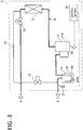
- a refrigeration unit 3 according to the third embodiment illustrated in FIG. 3 includes a refrigerant circuit including a configuration similar to that of the refrigeration unit 1 of the first embodiment, a control section 24, the pressure sensor 21, and a temperature sensor 25.
- the temperature of the refrigerating machine oil in the compressor 11 or temperature allowing for estimation of the temperature of the refrigerating machine oil in the compressor 11 is used in control.
- the temperature sensor 25 is disposed on a lower outer periphery of the housing 11A in order to detect the temperature of the refrigerating machine oil accumulated in the housing 11A of the compressor 11.
- the control section 24 calculates a degree of superheat of the refrigerating machine oil (hereinafter, degree of oil superheat) from a difference between the temperature detected by the temperature sensor 25 and the suction pressure saturation temperature detected by the pressure sensor 21.
- degree of oil superheat is used as an index of the returning situation of the refrigerating machine oil to the compressor 11.
- the degree of oil superheat is calculated from a difference between the saturation temperature corresponding to discharge pressure and one of the temperature and the estimated temperature of the refrigerating machine oil in the compressor 11.
- the saturation temperature is calculated from the discharge pressure detected by a pressure sensor that is installed on the discharge side of the compressor 11.
- bypass measures are taken only in the case where improvement of the oil returning property is required based on the degree of oil superheat in considering the refrigerating capacity.
- the two degrees of superheat (first degree of superheat and second degree of superheat) as the prescribed degrees of superheat are used in the control in order to avoid hunting.
- the control according to the bypass measures may be performed with use of only one prescribed degree of superheat.
- the bypass valve 16 is controlled by the control section 24 and the bypass route 15 is accordingly opened.
- bypass valve 16 is controlled by the control section 24 and the bypass route 15 is accordingly closed.
- the bypass route 15 is preferably closed to inhibit further progression of dilution.
- the third embodiment it is possible to limitedly take the bypass measures only in the case where improvement of the oil returning property is necessary based on the degree of oil superheat allowing for estimation of an amount of the refrigerating machine oil dissolved in the liquid refrigerant inside the compressor 11. Therefore, it is possible to prevent poor lubrication and seizure in the compressor 11 while suppressing deterioration of refrigerating capacity.
- control in the above-described third embodiment may be modified in the following manner.
- control section 24 may be configured to control the bypass valve 16 to open the bypass route 15 only in a case where the degree of superheat of the refrigerating machine oil accumulated in the compressor 11 is higher than the prescribed degree of superheat every time the integrated operation time of the refrigeration unit 3 reaches 60 minutes and the suction pressure saturation temperature is equal to or lower than -30°C as the prescribed value.
- the bypass valve 16 is controlled and the bypass route 15 is closed to terminate the bypass measures.
- Different indices may be used for the start condition of the bypass measures and for the termination condition of the bypass measures.
- control may be performed to start the bypass measures when the liquid level of the refrigerating machine oil in the compressor 11 becomes lower than the prescribed liquid level, and to terminate the bypass measures when the prescribed time elapses after the start of the bypass measures or the degree of superheat of the refrigerating machine oil in the compressor 11 is suppressed by the bypass measures to at least the prescribed degree of superheat.
- Application of the present invention is not limited to the refrigeration system including a refrigerator/freezer case and the condensing unit configuring the system.
- the present invention is applicable to a refrigeration system relating to an air conditioner, a container, and the like, and a refrigeration unit configuring the system.
- the bypass valve 16 is not necessarily a switching valve, and may be configured as a flow rate regulation valve that regulates the flow rate of the refrigerant flowing through the bypass route 15.
- the control section 20 is configured to control an opening degree of the bypass valve 16 such that a small amount of refrigerant flows through the bypass route 15. Further, when the evaporation temperature is set to a low temperature, the control section 20 is configured to controls the bypass valve 16 so as to increase the flow rate of the refrigerant flowing through the bypass route 15, based on the condition under which deterioration of the oil returning property from the gas-liquid separator 14 to the compressor 11 is expected.
- the bypass measures of increasing the flow rate of the refrigerant flowing through the bypass route 15 are preferably taken intermittently every predetermined time, or are preferably taken only in a case where improvement of the oil returning property is necessary according to the returning situation of the refrigerating machine oil indicated by the liquid level or the degree of superheat of the refrigerating machine oil in the compressor 11.
- the flow rate of the refrigerant flowing through the bypass route 15 is preferably reduced through the control of the bypass valve 16 when a predetermined time elapses after the flow rate of the refrigerant to be bypassed is increased or necessity of the bypassing is eliminated from the oil returning situation.
- bypass valve 16 may be provided at, for example, a start end of the bypass route 15 branched from a main stream on the outlet side of the heat exchanger 12.
Landscapes
- Engineering & Computer Science (AREA)
- Physics & Mathematics (AREA)
- Mechanical Engineering (AREA)
- Thermal Sciences (AREA)
- General Engineering & Computer Science (AREA)
- Chemical & Material Sciences (AREA)
- Analytical Chemistry (AREA)
- Power Engineering (AREA)
- Applications Or Details Of Rotary Compressors (AREA)
Applications Claiming Priority (1)
| Application Number | Priority Date | Filing Date | Title |
|---|---|---|---|
| JP2017107271A JP2018204805A (ja) | 2017-05-31 | 2017-05-31 | 冷凍ユニット、冷凍システム、および冷媒回路の制御方法 |
Publications (1)
| Publication Number | Publication Date |
|---|---|
| EP3410037A1 true EP3410037A1 (de) | 2018-12-05 |
Family
ID=62492558
Family Applications (1)
| Application Number | Title | Priority Date | Filing Date |
|---|---|---|---|
| EP18175305.4A Withdrawn EP3410037A1 (de) | 2017-05-31 | 2018-05-31 | Kühleinheit, kühlsystem und verfahren zur steuerung eines kühlkreislaufs |
Country Status (2)
| Country | Link |
|---|---|
| EP (1) | EP3410037A1 (de) |
| JP (1) | JP2018204805A (de) |
Cited By (3)
| Publication number | Priority date | Publication date | Assignee | Title |
|---|---|---|---|---|
| CN113551447A (zh) * | 2020-04-14 | 2021-10-26 | 青岛海尔空调器有限总公司 | 制热模式下空调系统的压缩机回油控制方法和控制系统 |
| CN115574501A (zh) * | 2022-10-13 | 2023-01-06 | 杭州长川科技股份有限公司 | 回油控制装置及方法、制冷模块及系统、芯片测试分选机 |
| CN117450693A (zh) * | 2023-12-25 | 2024-01-26 | 珠海格力电器股份有限公司 | 压缩机回油控制方法、装置、计算机设备和存储介质 |
Families Citing this family (2)
| Publication number | Priority date | Publication date | Assignee | Title |
|---|---|---|---|---|
| CN113339946B (zh) * | 2021-05-19 | 2022-08-30 | 广东Tcl智能暖通设备有限公司 | 空调器运行控制方法、装置、空调器和计算机存储介质 |
| WO2025243515A1 (ja) * | 2024-05-24 | 2025-11-27 | 日立ジョンソンコントロールズ空調株式会社 | 冷凍サイクル装置および制御方法 |
Citations (7)
| Publication number | Priority date | Publication date | Assignee | Title |
|---|---|---|---|---|
| JPH0579357U (ja) | 1992-03-19 | 1993-10-29 | 三菱重工業株式会社 | 空気調和機 |
| JPH085185A (ja) * | 1994-06-16 | 1996-01-12 | Mitsubishi Electric Corp | 冷凍サイクルシステム |
| EP0848214A2 (de) * | 1996-12-12 | 1998-06-17 | Sanyo Electric Co. Ltd | Verfahren zur Rückführung von Kältemaschineöl in einer Klimaanlage |
| JP2004263995A (ja) * | 2003-03-04 | 2004-09-24 | Toshiba Kyaria Kk | 空気調和装置 |
| JP2010210208A (ja) | 2009-03-12 | 2010-09-24 | Mitsubishi Electric Corp | 空気調和装置 |
| EP2873935A1 (de) * | 2012-05-23 | 2015-05-20 | Daikin Industries, Ltd. | Tiefkühlgerät |
| WO2016194186A1 (ja) * | 2015-06-03 | 2016-12-08 | 三菱電機株式会社 | 冷凍サイクル装置および空気調和装置 |
-
2017
- 2017-05-31 JP JP2017107271A patent/JP2018204805A/ja active Pending
-
2018
- 2018-05-31 EP EP18175305.4A patent/EP3410037A1/de not_active Withdrawn
Patent Citations (7)
| Publication number | Priority date | Publication date | Assignee | Title |
|---|---|---|---|---|
| JPH0579357U (ja) | 1992-03-19 | 1993-10-29 | 三菱重工業株式会社 | 空気調和機 |
| JPH085185A (ja) * | 1994-06-16 | 1996-01-12 | Mitsubishi Electric Corp | 冷凍サイクルシステム |
| EP0848214A2 (de) * | 1996-12-12 | 1998-06-17 | Sanyo Electric Co. Ltd | Verfahren zur Rückführung von Kältemaschineöl in einer Klimaanlage |
| JP2004263995A (ja) * | 2003-03-04 | 2004-09-24 | Toshiba Kyaria Kk | 空気調和装置 |
| JP2010210208A (ja) | 2009-03-12 | 2010-09-24 | Mitsubishi Electric Corp | 空気調和装置 |
| EP2873935A1 (de) * | 2012-05-23 | 2015-05-20 | Daikin Industries, Ltd. | Tiefkühlgerät |
| WO2016194186A1 (ja) * | 2015-06-03 | 2016-12-08 | 三菱電機株式会社 | 冷凍サイクル装置および空気調和装置 |
Cited By (4)
| Publication number | Priority date | Publication date | Assignee | Title |
|---|---|---|---|---|
| CN113551447A (zh) * | 2020-04-14 | 2021-10-26 | 青岛海尔空调器有限总公司 | 制热模式下空调系统的压缩机回油控制方法和控制系统 |
| CN115574501A (zh) * | 2022-10-13 | 2023-01-06 | 杭州长川科技股份有限公司 | 回油控制装置及方法、制冷模块及系统、芯片测试分选机 |
| CN117450693A (zh) * | 2023-12-25 | 2024-01-26 | 珠海格力电器股份有限公司 | 压缩机回油控制方法、装置、计算机设备和存储介质 |
| CN117450693B (zh) * | 2023-12-25 | 2024-05-03 | 珠海格力电器股份有限公司 | 压缩机回油控制方法、装置、计算机设备和存储介质 |
Also Published As
| Publication number | Publication date |
|---|---|
| JP2018204805A (ja) | 2018-12-27 |
Similar Documents
| Publication | Publication Date | Title |
|---|---|---|
| EP3410037A1 (de) | Kühleinheit, kühlsystem und verfahren zur steuerung eines kühlkreislaufs | |
| US9683768B2 (en) | Air-conditioning apparatus | |
| EP2787305B1 (de) | Kühl-/klimaanlagenvorrichtung | |
| KR101460426B1 (ko) | 터보 냉동 장치, 그 제어 장치 및 그 제어 방법 | |
| US10208987B2 (en) | Heat pump with an auxiliary heat exchanger for compressor discharge temperature control | |
| US9976783B2 (en) | Refrigeration cycle apparatus | |
| US9989284B2 (en) | Refrigeration apparatus | |
| JP4767199B2 (ja) | 空気調和システムの運転制御方法並びに空気調和システム | |
| US10900695B2 (en) | Refrigeration cycle apparatus | |
| US11598559B2 (en) | Heat source-side unit and refrigeration apparatus | |
| CN110709649B (zh) | 制冷循环装置 | |
| CN108954501B (zh) | 空调机 | |
| JP2002257427A (ja) | 冷凍空調装置、及びその運転方法 | |
| JP2016205729A (ja) | 冷凍サイクル装置 | |
| JP2005083704A (ja) | 冷凍サイクル、空気調和機 | |
| US11512876B2 (en) | Refrigeration apparatus | |
| JP2015102256A (ja) | 空気調和機 | |
| JP4274250B2 (ja) | 冷凍装置 | |
| WO2018193498A1 (ja) | 冷凍サイクル装置 | |
| JPH085167A (ja) | 空気調和装置 | |
| CN108603697B (zh) | 冷冻装置 | |
| CN113383201B (zh) | 制冷循环装置 | |
| KR102017405B1 (ko) | 히트 펌프 | |
| US20260110473A1 (en) | System and method for lubricant quality control of an hvacr system | |
| EP4382827A1 (de) | Kältekreislaufvorrichtung und kältekreislaufsteuerungsverfahren |
Legal Events
| Date | Code | Title | Description |
|---|---|---|---|
| PUAI | Public reference made under article 153(3) epc to a published international application that has entered the european phase |
Free format text: ORIGINAL CODE: 0009012 |
|
| STAA | Information on the status of an ep patent application or granted ep patent |
Free format text: STATUS: REQUEST FOR EXAMINATION WAS MADE |
|
| 17P | Request for examination filed |
Effective date: 20180531 |
|
| AK | Designated contracting states |
Kind code of ref document: A1 Designated state(s): AL AT BE BG CH CY CZ DE DK EE ES FI FR GB GR HR HU IE IS IT LI LT LU LV MC MK MT NL NO PL PT RO RS SE SI SK SM TR |
|
| AX | Request for extension of the european patent |
Extension state: BA ME |
|
| STAA | Information on the status of an ep patent application or granted ep patent |
Free format text: STATUS: EXAMINATION IS IN PROGRESS |
|
| 17Q | First examination report despatched |
Effective date: 20190405 |
|
| STAA | Information on the status of an ep patent application or granted ep patent |
Free format text: STATUS: THE APPLICATION IS DEEMED TO BE WITHDRAWN |
|
| 18D | Application deemed to be withdrawn |
Effective date: 20191211 |