EP3411183B1 - Vorrichtung zum automatischen wechsel von schleifscheiben - Google Patents
Vorrichtung zum automatischen wechsel von schleifscheiben Download PDFInfo
- Publication number
- EP3411183B1 EP3411183B1 EP17702386.8A EP17702386A EP3411183B1 EP 3411183 B1 EP3411183 B1 EP 3411183B1 EP 17702386 A EP17702386 A EP 17702386A EP 3411183 B1 EP3411183 B1 EP 3411183B1
- Authority
- EP
- European Patent Office
- Prior art keywords
- grinding wheel
- grinding
- positioning
- separating
- positioning element
- Prior art date
- Legal status (The legal status is an assumption and is not a legal conclusion. Google has not performed a legal analysis and makes no representation as to the accuracy of the status listed.)
- Active
Links
Images

Classifications
-
- B—PERFORMING OPERATIONS; TRANSPORTING
- B24—GRINDING; POLISHING
- B24B—MACHINES, DEVICES, OR PROCESSES FOR GRINDING OR POLISHING; DRESSING OR CONDITIONING OF ABRADING SURFACES; FEEDING OF GRINDING, POLISHING, OR LAPPING AGENTS
- B24B27/00—Other grinding machines or devices
- B24B27/0038—Other grinding machines or devices with the grinding tool mounted at the end of a set of bars
-
- B—PERFORMING OPERATIONS; TRANSPORTING
- B23—MACHINE TOOLS; METAL-WORKING NOT OTHERWISE PROVIDED FOR
- B23Q—DETAILS, COMPONENTS, OR ACCESSORIES FOR MACHINE TOOLS, e.g. ARRANGEMENTS FOR COPYING OR CONTROLLING; MACHINE TOOLS IN GENERAL CHARACTERISED BY THE CONSTRUCTION OF PARTICULAR DETAILS OR COMPONENTS; COMBINATIONS OR ASSOCIATIONS OF METAL-WORKING MACHINES, NOT DIRECTED TO A PARTICULAR RESULT
- B23Q3/00—Devices holding, supporting, or positioning work or tools, of a kind normally removable from the machine
- B23Q3/155—Arrangements for automatic insertion or removal of tools, e.g. combined with manual handling
- B23Q3/1552—Arrangements for automatic insertion or removal of tools, e.g. combined with manual handling parts of devices for automatically inserting or removing tools
- B23Q3/15526—Storage devices; Drive mechanisms therefor
-
- B—PERFORMING OPERATIONS; TRANSPORTING
- B24—GRINDING; POLISHING
- B24D—TOOLS FOR GRINDING, BUFFING OR SHARPENING
- B24D9/00—Wheels or drums supporting in exchangeable arrangement a layer of flexible abrasive material, e.g. sandpaper
- B24D9/08—Circular back-plates for carrying flexible material
- B24D9/085—Devices for mounting sheets on a backing plate
-
- B—PERFORMING OPERATIONS; TRANSPORTING
- B23—MACHINE TOOLS; METAL-WORKING NOT OTHERWISE PROVIDED FOR
- B23Q—DETAILS, COMPONENTS, OR ACCESSORIES FOR MACHINE TOOLS, e.g. ARRANGEMENTS FOR COPYING OR CONTROLLING; MACHINE TOOLS IN GENERAL CHARACTERISED BY THE CONSTRUCTION OF PARTICULAR DETAILS OR COMPONENTS; COMBINATIONS OR ASSOCIATIONS OF METAL-WORKING MACHINES, NOT DIRECTED TO A PARTICULAR RESULT
- B23Q3/00—Devices holding, supporting, or positioning work or tools, of a kind normally removable from the machine
- B23Q3/155—Arrangements for automatic insertion or removal of tools, e.g. combined with manual handling
- B23Q3/1552—Arrangements for automatic insertion or removal of tools, e.g. combined with manual handling parts of devices for automatically inserting or removing tools
- B23Q3/15526—Storage devices; Drive mechanisms therefor
- B23Q2003/15527—Storage devices; Drive mechanisms therefor the storage device including means to latch tools
-
- B—PERFORMING OPERATIONS; TRANSPORTING
- B23—MACHINE TOOLS; METAL-WORKING NOT OTHERWISE PROVIDED FOR
- B23Q—DETAILS, COMPONENTS, OR ACCESSORIES FOR MACHINE TOOLS, e.g. ARRANGEMENTS FOR COPYING OR CONTROLLING; MACHINE TOOLS IN GENERAL CHARACTERISED BY THE CONSTRUCTION OF PARTICULAR DETAILS OR COMPONENTS; COMBINATIONS OR ASSOCIATIONS OF METAL-WORKING MACHINES, NOT DIRECTED TO A PARTICULAR RESULT
- B23Q3/00—Devices holding, supporting, or positioning work or tools, of a kind normally removable from the machine
- B23Q3/155—Arrangements for automatic insertion or removal of tools, e.g. combined with manual handling
- B23Q3/1552—Arrangements for automatic insertion or removal of tools, e.g. combined with manual handling parts of devices for automatically inserting or removing tools
- B23Q3/15526—Storage devices; Drive mechanisms therefor
- B23Q2003/15528—Storage devices; Drive mechanisms therefor the storage device including means to project tools therefrom, e.g. for transferring them
-
- Y—GENERAL TAGGING OF NEW TECHNOLOGICAL DEVELOPMENTS; GENERAL TAGGING OF CROSS-SECTIONAL TECHNOLOGIES SPANNING OVER SEVERAL SECTIONS OF THE IPC; TECHNICAL SUBJECTS COVERED BY FORMER USPC CROSS-REFERENCE ART COLLECTIONS [XRACs] AND DIGESTS
- Y10—TECHNICAL SUBJECTS COVERED BY FORMER USPC
- Y10T—TECHNICAL SUBJECTS COVERED BY FORMER US CLASSIFICATION
- Y10T483/00—Tool changing
- Y10T483/17—Tool changing including machine tool or component
- Y10T483/1733—Rotary spindle machine tool [e.g., milling machine, boring, machine, grinding machine, etc.]
- Y10T483/1736—Tool having specific mounting or work treating feature
- Y10T483/174—Abrading wheel
Definitions
- the invention relates to a device for automatically changing grinding wheels according to the preamble of patent claim 1.
- the invention also relates to a system comprising a device for automatically changing grinding wheels according to claim 11.
- An automatic grinder includes a tool head with a grinding wheel mount.
- This receiving device is designed, for example, as a sanding pad that contains a Velcro connection that can be designed in particular as a Velcro® pad.
- a sanding disc can be placed on the sanding pad and held on the sanding pad by the hook-and-loop fastener. The hooks on the hook and loop fastener grip the felt-like surface of the sanding disc so that the sanding disc is held on the surface of the sanding pad by the hook and loop fastener on the tool.
- the sanding disc can perform a rotary movement or an eccentric movement, or a combination in the manner of a tumbling movement, so that any surface of a workpiece with any shape can be polished with the grinding tool.
- the tool head can be part of a manipulation device, for example, the tool head on a Be manipulation arm attached, especially on a robot arm.
- Robot arms for various applications are, for example, from the WO2015074089A1 famous.
- a robot arm consists of several arm segments, damping elements for coupling the first and second arm segment, a sensor for detecting the position of the first arm segment in relation to the second arm segment and a control unit which controls the drive motor for the robot arm depending on the sensor signal received and which Robot arm moved to a target position when no force is applied to the robot arm.
- Such a robot arm is used, for example, for stacking objects, which in the WO2014205475A1 is shown. If one wants to position such objects precisely, the object must be gripped by a manipulator and moved precisely, according to WO2014205475A1 an actuator is used, which is arranged between the manipulator and the object to be positioned.
- Grinding wheels must be replaced periodically as wearing parts.
- One way of changing the grinding wheels is to interrupt the grinding process, turn off the grinding device and change the grinding wheel manually, because the complexity of this work process, as stated above, has made it appear uneconomical to automate it.
- WO 2015/125068 A1 discloses an apparatus for automatically changing grinding wheels according to the preamble of claim 1.
- a storage container with abrasives stacked one on top of the other and precisely aligned with respect to the suction openings for sanding dust is known.
- the abrasives are stacked one on top of the other and are arranged on a plate that is guided exactly vertically in a cylinder. This cannot be rotated or moved in the x or y direction, so that the individual grinding wheels can only be picked up with a robot arm in a single position that is positioned exactly in front. Slight deviations in the position of the robot arm mean that the grinding wheels cannot be picked up.
- a stacking container is also known, with grinding wheels arranged thereon that lie exactly one on top of the other and which can be presented in packs to an automated grinding plant.
- the grinding wheels are held horizontally immobile, which is why the gripping by a robot arm has to be carried out with the greatest precision.
- the detachment station is designed as a horizontal base on which the tool head with the grinding wheel to be replaced can be placed.
- a slider is placed between the grinding wheel and the Tool head positioned and the grinding wheel pressed against the base with the slide.
- the grinding wheel is retained by the slide.
- the slider is then returned to its original position and the pad is tilted so that the used grinding wheel can be disposed of.
- the tool head then moves to an alignment station, which is used to position the tool head in a defined position so that a new grinding wheel can be positioned correctly on the tool head.
- the station contains sensors which detect the target position of the suction openings on the tool head and switch on the servomotor of the tool head via a controller in order to bring the tool head into the target position.
- the alignment station is followed by a loading station which contains a stack of new grinding wheels.
- the aligned tool head can be precisely positioned on the stack of grinding wheels to remove the top wheel from the stack.
- the Grinding wheel remains stuck in the correct position, correct position being understood to mean a position in which the suction openings on the tool head are above the openings in the grinding wheel.
- a device for automatically changing grinding wheels according to the EP 2 842 689 B1 designed.
- Such a device has a stop element for removing a grinding wheel from a grinding tool, against which the top plate with the grinding wheel can be placed in a removal position, at least one removal finger which can be adjusted between a retracted position and an engaged position, and a clamping device by which the removal finger is displaceable relative to the stop element.
- the grinding wheel can be clamped to the stop element by means of the removal finger.
- the removal finger is free of sharp edges, so that damage to the grinding wheel and, as a result, a possible abortion of the removal process due to incompletely removed grinding wheels or blocking of the removal device is avoided.
- the fingers of the grinding wheel holder engage in corresponding grooves on the grinding wheel support of the tool.
- the grinding wheel support must be manufactured exactly according to the specifications of the grinding wheel mounting device.
- the grinding wheel dispenser is formed as a cylindrical cavity in which a plurality of grinding wheels are stacked one on top of the other.
- the inside diameter of the cavity is slightly larger than the outside diameter of the grinding wheels.
- the grinding wheels contain a plurality of holes. Through two of these holes is one Mandrel passed so that the grinding wheels are fixed in a certain position by the corresponding mandrel. From the above description it can be inferred that the automatic replacement of grinding wheels still implies a complicated process, which requires the double alignment of the tool head when removing the grinding wheel and when picking up a new grinding wheel.
- the object of the present invention is to provide a device to simplify the automated changing of the grinding wheel.
- the object of the invention is to align the grinding wheel holder of the grinding tool and the grinding wheel in a simplified manner in such a way that suction openings for grinding material arranged in the grinding wheel holder are aligned with corresponding openings arranged on the grinding wheel, so that the suction of abrasion by the grinding wheel is not hindered.
- a device for automatically changing grinding wheels comprises a stacking device for a plurality of grinding wheels, and a guide element for aligning the grinding wheels one on top of the other a common central axis, the guide element being arranged eccentrically with respect to the central axis.
- a positioning element for positioning a tool head is provided, with the positioning element and the guide element being mounted in a floating manner.
- the positioning element is arranged in particular along the central axis, so that the central axis corresponds to the longitudinal axis of the positioning element.
- the positioning element is in particular a rotationally symmetrical body whose axis of symmetry is the central axis.
- the positioning element can be designed as a cylinder.
- the advantage of this floating bearing is that the tool can be positioned very easily on the positioning element. A hole in the tool captures the centrally located positioning element with a conical upper end and can be placed on this even if the tool does not hit the positioning element exactly in the middle, since the position of the tool head with the grinding wheel holder can be compensated for via the floating bearing. Thus, when positioning the tool head with the grinding wheel holder on the positioning element of the stacking device, there is a time saving and reduced requirements regarding the precision of the positioning.
- a base element for accommodating the positioning element and the guide element.
- the floor element can vibrate an element, for example at least one Spring element included, by which a movement of the base element in a radial direction with respect to the central axis is permitted.
- the floor element can also be designed as an intermediate floor, which is arranged in a stacking device and is held by the resilient elements.
- the floor element can be suspended in a housing of a stacking device.
- the vibratable element can also contain an elastic material, wherein the elastic material can be reversibly expandable or compressible in the radial direction.
- the radial direction is understood as meaning any deflection of the central axis in a plane containing the base element that is normal to the central axis.
- the floor element is also arranged horizontally.
- the normal plane is a horizontal plane. If a Cartesian coordinate system is arranged in this horizontal plane in such a way that the z-axis corresponds to the central axis, the floor element can move in at least one of the x or y-axes.
- the positioning element can be moved axially, in particular in the direction of the central axis.
- the positioning element can be designed as a rod which is accommodated in the base element.
- the positioning element can be accommodated in a bore in the base element, with a spacer element being arranged in the bore.
- the spacer element is thus located at or below the lower end of the positioning element. That The positioning element can thus deviate in the axial direction when it comes into contact with a grinding wheel holder of a tool head, so that there is gentle contact between the positioning element and the grinding wheel plate. As a result, damage to the grinding wheel holder can be avoided when finding the position, since no harmful forces are introduced into the grinding wheel holder when it comes into contact with the positioning element.
- the spacer element can contain at least one element from the group of spring elements, elastic elements or magnetizable elements.
- the positioning element has a greater height than the guide element. This ensures that during the positioning process for determining the radial position, the grinding wheel holder is touched by the positioning element and not by the guide elements. That is, the center axis of the grinding wheel holder is brought into agreement with the center axis of the stacker.
- the grinding wheel holder can be moved freely in order to be able to wobble during the grinding process. Due to this free mobility in the direction of rotation, however, the exact whereabouts of the grinding wheel or of its centrally arranged opening is not known until the grinding wheel holder is received on the positioning element. As soon as the upper end of the positioning element engages in the grinding wheel holder, the axial alignment of the grinding wheel holder in relation to the central axis of the grinding wheels or the positioning element is predetermined.
- the guide element passes through one of the openings, which are arranged eccentrically to the central opening and which are provided in the grinding wheel, in order to enable the suction of abraded material during operation.
- the positioning element is designed as a rod, the positioning element having a lower end which is accommodated in the bore and an upper end which protrudes beyond the uppermost grinding wheel, the upper end in particular comprising a conical section.
- the grinding wheel seat is thus in this position in which it is placed on the conical portion, i.e. not yet in contact with the guide element.
- the grinding wheel holder is therefore freely rotatable about the positioning element, so that the correct position of the grinding wheel in relation to the grinding wheel holder can be set in a subsequent radial adjustment.
- this position can be found by means of a recognition device.
- This position can be found, for example, using a single sensor.
- the sensor can be a sensor like the one in the DE 20 2013 101 858 U1 or the EP 2 842 689 B1 is described to be.
- only a single sensor is required, since only the angular position of the recess of the grinding wheel holder in relation to the opening in the grinding wheel has to be determined.
- the tool head controller is instructed to rotate the tool head and thus the grinding wheel holder into the position in which the opening in the grinding wheel and the recess on the grinding wheel holder are aligned.
- the grinding wheel holder can be set in rotation by means of a drive element.
- the drive element can contain a nozzle, for example, by means of which a jet of pressurized fluid can be generated.
- the jet of pressurized fluid can be a jet of compressed air, but other fluids, in particular gases, can also be used.
- the drive element could have any other construction known to the person skilled in the art in order to bring about a rotary movement of the grinding wheel holder.
- the grinding wheel holder could be connected to the drive element in a non-positive or frictional manner.
- the grinding wheel holder can have, for example, a ring gear that can be coupled to a drive pinion.
- the drive element can contain a magnet or a magnetizable material which is connected to a corresponding counter-element can be coupled to the grinding wheel holder.
- the drive element designed as a nozzle serves to direct a jet of pressurized fluid onto the grinding wheel holder in order to set the grinding wheel holder in a rotary motion.
- the rotational speed of the rotational movement and/or the desired distance can be adjusted by the duration and/or intensity of the jet of pressurized fluid.
- a pressurized fluid pulse with a duration of preferably a maximum of 1 second can be applied to the grinding wheel mount, so that the grinding wheel mount can be set in rotary motion.
- the rotational movement can be regulated in such a way that the grinding wheel holder comes to rest in a position above the grinding wheel in which the openings in the grinding wheel are aligned with the recesses in the grinding wheel holder when the correct position has been reached.
- this position can be found by means of a detection device, for example by means of a single sensor.
- the drive element has a controller, by means of which the correct position of the grinding wheel holder can be determined. As described above, the drive element can, for example, initiate a rotary movement of the grinding wheel holder.
- This drive element does not have to be located in the tool head, which means that the construction of the tool head can be simplified because the tool head does not require a drive that is suitable for adjusting the grinding wheel holder.
- the intensity of the jet of pressurized fluid can be regulated.
- the outlet speed of the pressurized fluid can be changed by changing the flow cross section of the nozzle opening, so that the grinding wheel holder can be moved into the position specified by the detection device by controlling the drive element.
- the stacking device is accommodated in a container.
- the container contains a container base and a container lid with an opening through which one of the grinding wheels can be removed.
- the diameter of the opening is larger than the diameter of the grinding wheel.
- a retaining element can be provided which protrudes into the opening.
- a plurality of such retaining elements can be provided.
- the retaining elements can be displaceable so that they can be adjusted from a holding position to a removal position. For example, while the grinding wheel is being positioned on the grinding wheel mount, they can at least partially uncover the opening so that the grinding wheel can be removed more easily. As soon as the grinding wheel is positioned on the grinding wheel holder, the Retainer brought back into the holding position so that the stack of grinding wheels is held in the opening.
- the stack of grinding wheels can be held by a support element which can be displaced in relation to the guide element and the positioning element by means of a clamping element.
- the clamping element can be designed as a spring element.
- the spring element can be arranged between the intermediate floor and the support element.
- the support element can be guided by means of a lifting element.
- the lifting element enables the support element to be adjusted step by step, so that after a grinding wheel has been removed, the grinding wheel underneath moves up to its position.
- the lifting element can contain a fluid cylinder, an electric motor, spring-loaded detent elements or the like.
- a lifting element for stepwise tracking of the grinding wheels can be used in particular when dimensionally stable grinding wheels are used.
- a dimensionally stable grinding wheel is understood to mean a grinding wheel that deforms only under the action of a force that is at least twice the weight of the grinding wheel itself.
- a flexible grinding wheel is understood to mean a grinding wheel that can deform under the influence of its own weight.
- a grinding wheel can, for example a sandpaper or a polishing cloth, for example made of leather or a textile material.
- the grinding wheel holder can be set into a rotational movement by the drive element, with this rotational movement not having to be regulated in contrast to the previous exemplary embodiments.
- the guide element can be axially displaceable by means of an actuating element.
- the rotating grinding wheel holder is moved in the direction of the grinding wheel until the guide element touches the surface of the grinding wheel.
- the guide element can be displaced in the axial direction.
- the guide element can contain an actuating element which is arranged in the bore.
- This actuating element can be designed as a tensioning element.
- the clamping element is pre-tensioned when the grinding wheel holder presses on the guide element.
- the tensioning element can comprise a spring. This slightly compresses the clamping element of the guide element, so that the upper end of the guide element exerts a small amount of contact pressure on the grinding wheel holder. As soon as the upper end of the guide element finds a recess in the grinding wheel holder, the clamping element can relax again.
- the end of the guide element on the grinding wheel mount engages with the recess, as a result of which the rotary movement of the grinding wheel mount is stopped.
- the correct position of the grinding wheel holder has been reached.
- the grinding wheel holder can now be moved towards the grinding wheel in order to pick up the grinding wheel from the grinding wheel stack.
- the actuating element can also comprise a magnetizable element which is attached to the upper end of the guide element.
- a magnetizable counter-element can be arranged in the bore for this magnetizable element, with the magnetizable element of the upper end of the guide element and the magnetizable counter-element repelling one another in the bore.
- a plurality of guide elements can be provided.
- two or more guide elements can be provided in order to distribute the force that acts on the guide element when the rotational movement is interrupted over two or more guide elements, so that each Guide element only has to absorb the corresponding fraction of the force.
- the upper end of the guide element can contain a magnetizable element at the top, in particular the upper end can contain a magnet.
- This magnet can be attracted to a corresponding magnetizable counter element in the grinding wheel holder when the grinding wheel holder is engaged with the positioning element and a recess comes to lie over the magnetizable end element during rotation.
- the magnetizable element can in particular be contained in the recess of the grinding wheel holder.
- the object of the invention is to easily detach a used grinding wheel from a grinding wheel holder, with the device for detaching the grinding wheel not having any moving parts.
- a device for automatically changing grinding wheels comprises a detachment device for grinding wheels, the detachment device comprising a support surface for a grinding wheel holder.
- the support surface has an opening whose diameter is larger than the diameter of the grinding wheel is.
- a divider is positioned above the opening. The separating element can partially cover the opening so that the grinding wheel holder cannot get into the opening.
- the separating element can have a separating edge, wherein the separating edge can comprise a tip.
- a plurality of tips can also be provided for the separating edge.
- a v-shaped tip can be provided.
- a tip can be used, the edges of which are asymmetrical, for example in the form of a guillotine.
- a w-shaped tip may be used.
- a w-shaped tip may have two tip elements.
- a jagged profile containing a plurality of peaks may be provided.
- the separating element can have ribs which are aligned in particular in the direction of movement of the grinding wheel holder. These ribs can increase the dimensional stability or support the process of detaching the grinding wheel from the grinding wheel holder.
- the ribs can only be on one side of the separating element, they can also be arranged on both sides.
- the separating element can be designed as a disk, which has a wall thickness, at least along the separating edge, that is smaller than the distance between the grinding disk and the grinding disk mount.
- the separating element can be designed as a thin-walled metal sheet.
- the separating element is detachably fastened to the support surface by means of connecting means.
- the separating element can be detached from the support surface, for example in order to replace it with a separating element of a different configuration.
- the detachment device can thus be used for a large number of different grinding wheels.
- a spacer element can be provided between the separating element and the supporting surface.
- the spacing of the separating element from the support surface can be adjusted by means of the spacer element.
- the use of a spacer element makes it possible to use the device for different types of grinding wheels.
- a grinding wheel can be arranged on the grinding wheel mount in such a way that the grinding wheel protrudes radially beyond the grinding wheel mount.
- the edge of such a grinding wheel can bend up so that the edge comes to rest above the cutting edge.
- a tilting divider can be used.
- the tiltable separating element is arranged in such a way that, in the tilted state, the separating edge or at least its tip is located somewhat higher than the opposite end of the separating element.
- a tilting mechanism is actuated at this point by the grinding wheel holder, which tilts the cutting edge in the direction of the support surface, so that the angle of attack of the cutting element can be reduced.
- the cutting edge catches the edge of the grinding wheel and pushes it towards the support surface. Then the movement of the grinding wheel holder can be continued.
- the separating element can gradually remove the grinding wheel from the grinding wheel holder.
- the separating element can have more than one separating edge.
- the separating edges can be arranged on more than one side edge of the separating element.
- such a detachment device can be used simultaneously for two or more different types of grinding wheels.
- the wall thickness of the separating element at the separating edge is therefore preferably less than 5 mm, in particular the wall thickness has a maximum value in the range of 1 mm.
- the separating element can include a deflection element which can assist in detaching the grinding wheel.
- a method for detaching a grinding wheel from a grinding wheel holder comprises the following steps: the grinding wheel holder is placed over the one shown Bearing surface of the detachment device out, wherein the grinding wheel holder is in contact with the bearing surface.
- the grinding wheel is gripped by the separating element, which is inserted as a disk element with a separating edge of the grinding wheel holder over the separating edge between the grinding wheel and the support surface, as a result of which the grinding wheel is detached from the grinding wheel holder.
- the grinding wheel falls into an opening below the cutting edge.
- the used grinding wheels can be collected in a collection container located below the opening and disposed of properly.
- a dedicated alignment station for exact positioning of the tool head for receiving a new grinding wheel can be dispensed with, since the positioning takes place immediately before receiving a new grinding wheel.
- the device can be used for dimensionally stable and/or flexible grinding wheels.
- a system includes a device for automatically changing grinding wheels, containing a stacking device according to one of the preceding exemplary embodiments and a detaching device according to one of the preceding exemplary embodiments.
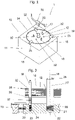
- the device 1 according to 1 for automatically changing grinding wheels comprises a stacking device 10 containing a plurality of grinding wheels 12 and a guide element 16 for aligning the grinding wheels 12 one above the other along a common central axis, the guide element 16 being arranged eccentrically with respect to the central axis.
- a positioning element 17 is provided for positioning a grinding wheel holder, the positioning element 17 and the guide element 16 being mounted in a floating manner.
- the stacking device 10 is accommodated in a container 11 .
- the container 11 has a container bottom 13 and a container lid 14 with an opening 15 through which one of the grinding wheels 12 can be removed.
- the diameter of the opening 15 is larger than the diameter of the grinding wheel 12.
- Three retaining elements 25 are provided which protrude into the opening 15 and hold the grinding wheels 12 in the stacking device 10. According to a variant that is not shown, the retaining element or elements 25 do not protrude into the opening.
- a positioning element 17 and three guide elements 16 are passed through the grinding wheels 12, the upper ends of which 1 are visible.
- the grinding wheels 12 have corresponding openings for this purpose, a central opening for the positioning element 17 and, in the present illustration, six openings 32. Three of these openings 32 contain a guide element 16.
- FIG 2 is a detail of a section through the stacking device 10 according to FIG 1 shown, which runs in a plane containing the central axis 18 of the positioning element 17 .
- the container 11 is omitted so as not to clutter the view.
- a bottom element 20 is provided for receiving the positioning element 17 and the guide element 16 in the container 11 .
- the base element 20 contains an element 19 capable of oscillating, for example a helical spring, by means of which a movement of the base element 20 in the radial direction in relation to the central axis 18 is made possible.
- the floor element 20 can form an intermediate floor in the container 11, which is above the in 1 shown container bottom 13 runs.
- the positioning element 17 has a greater height than the guide element 16 . This ensures that a grinding wheel holder 100, also known as a grinding wheel, which can be arranged on a tool head, first engages with the positioning element 16 before it touches the ends of the guide elements 16 on the grinding wheel support side.
- the tool head contains, for example, a freely rotatable grinding disk as a grinding wheel holder, which carries a grinding wheel 12 for carrying out a grinding process.
- the grinding wheel holder can perform a combined rotating and sliding movement, which results in a wobbling movement.
- a grinding wheel mount 100 is known from the prior art and is therefore not shown. Due to this wobbling motion, the position of the grinding wheel holder 100 with respect to the central axis 18 is not known when a grinding wheel holder 100 approaches the stacking device 10 to be loaded with a new grinding wheel 12 .
- the grinding wheel 12 In order to correctly position a grinding wheel 12 on the grinding wheel holder, the grinding wheel 12 must not only be positioned centrally on the grinding wheel holder 100, but the openings 32 on the grinding wheel 12 must be aligned with recesses 33 of the grinding wheel holder 100. These recesses 33 are used to extract abrasion that occurs during the grinding process.
- the abrasion can include, for example, abrasive particles, coolants, cleaning agents.
- the grinding wheel holder must therefore be positioned and adjusted each time the grinding wheel 12 is changed in relation to the grinding wheels 12 located in the stacking device 10 .
- Positioning is understood to mean a work step which brings the center axis of the grinding wheel holder 100 into line with the center axis 18 .
- Adjustment is understood as a work step which brings the openings 32 of the grinding wheel 12 into line with the recesses of the grinding wheel holder 100 .
- the grinding wheel holder 100 is guided over the free end 28 of the positioning element 17, the exact position of the central axis 18 of the positioning element 17 not being exactly known because the grinding wheel holder 100 is known to perform a wobbling movement.
- a cylindrical bore 101 is formed in the grinding wheel holder 100, the diameter D of which is larger than the upper conical end 28 of the positioning element 17.
- the base element 20 is designed as an oscillating element 19, which enables a movement of the positioning element 17 with the base element 20 in the radial direction in relation to the central axis 18, the positioning element 17, thanks to its conically tapering free upper end 28, can be inserted into the central hole in the Engage grinding wheel 12 and center with respect to the central bore 101 in the grinding wheel holder 100 .
- the positioning element 17 can be moved axially in the direction of the central axis 18 .
- the positioning element 17 is designed as a rod, which is partially accommodated with its lower end 29 in a bore 21 in the base element 20 .
- a spacer element 22 is arranged, which is shown as a spring.
- the grinding wheel mount can only rotate about the central axis 18 of the positioning element 17 as soon as the free end 28 of the positioning element 17 is in engagement with the bore 101 in the grinding wheel mount 100 . Therefore, the grinding wheel holder 100 has the central bore 101, the diameter of which corresponds to a diameter of the conical section of the free end 28 of the positioning element 17 or which is slightly larger than the diameter of the positioning element 17.
- the rotational movement of the grinding wheel holder 100 can be initiated or reinforced by a drive element 30, which is 1 is shown.
- the drive element 30 includes a nozzle, it being possible for a jet of pressurized fluid to be directed onto the grinding wheel mount 100 through the nozzle. By means of the pressure fluid jet the grinding wheel holder 100 is set in rotary motion.
- the adjustment work step can be carried out.
- the grinding wheel holder 100 is moved further down along the central axis 18 in the direction of the new grinding wheel 12 .
- the positioning element 17 is moved into the bore 21 against the spring force of the spacer element 22 .
- the guide element 16 or all the guide elements 16 are also displaced in the direction of the base element 20 .
- the lower end of the guide element 16 is pushed into a guide bore 24 .
- a spring element 23 is arranged between the bottom element-side end of the guide element 16 and the bottom of the guide bore 24 .
- the upper end of the guide member 16 is in contact with the rotating grinding wheel mount 100. As soon as the upper end of the guide member 16 meets the bore 101 in the grinding wheel mount, the guide member 16 is forced out of the guide bore 24 a distance. The upper end of the guide element 16 engages with the bore 101 of the grinding wheel holder 100 and blocks it, so that further rotational movement is prevented. In this position, the openings 32 of the grinding wheel 12 are exactly aligned with the recesses 33 of the grinding wheel holder 100. The grinding wheel holder 100 is thus correctly positioned to accommodate a grinding wheel 12.
- the grinding wheel holder 100 is lowered further down in the direction of the new grinding wheel 12 .
- One of the grinding wheels 12 can be removed from the opening 15 in each case.
- the diameter of the opening 15 is larger than the diameter of the grinding wheel 12. Therefore, one of the three retaining elements 25 is shown protruding into the opening 15 to hold the grinding wheels 12 in the stacking device 10.
- the stack of grinding wheels 12 is carried by a support member 26, e.g.
- the clamping element 27 is supported on the surface of the base element 20 .
- the grinding wheel holder 100 is lowered until it comes into contact with the grinding wheel 12 .
- the grinding wheel 12 adheres to the surface of the grinding wheel holder 100, whether by applying a vacuum to suck the grinding wheel 12, whether by means of a Velcro connection or a combination of different holding mechanisms.
- the grinding wheel holder 100 with the grinding wheel 12 is then moved away from the stacking device and is ready for a new use.
- the grinding wheel 12 is flexible, it will be pulled past the retaining elements 25 .
- the retaining elements 25 can be adjustable. For example, they can be hinged or slid outwards so that the grinding wheel 12 can pass through the opening unhindered.
- FIG 3 shows a variant of 2 according to which a lifting element 40 is provided for tracking the grinding wheels 12 of the grinding wheel stack.
- the detachment device 50 is used to remove a grinding wheel 12 from a grinding wheel holder 100 before changing the wheel.
- a device 1 for automatically changing grinding wheels 12 can include such a detachment device 50 .
- the worn or used grinding wheel 12 must be separated from the grinding wheel holder 100 .
- the detachment device 50 comprises a bearing surface 51.
- the bearing surface 51 has an opening 52, the diameter of which is larger than the diameter of the grinding wheel 12.
- a separator 53 is arranged above the opening 52 .
- the separating element 53 extends partially over the opening 52 so that the grinding wheel holder 100 cannot enter the opening 52 .
- the separating element 53 has at least one separating edge 54 .
- the separating edge 54 includes a tip 55 which points radially towards the edge of the opening 52 .
- the tip 55 can be v-shaped or w-shaped or asymmetrical be formed running edges.
- the tip 55 may have a serrated profile.
- the separating element 53 can also be designed as a disk, which has a wall thickness, at least along the separating edge 54, which is smaller than the distance between the grinding wheel 12 and the grinding wheel holder.
- the separating element 53 can be designed as a thin-walled metal sheet.
- the separating element 53 is detachably fastened to the support surface 51 with connecting means.
- a spacer element can be fitted between the separating element 53 and the bearing surface 51 in order to adjust the distance between the separating element 53 and the bearing surface 51 .
- the use of a spacer element makes it possible to use the device for different thick types of grinding wheels 12.
- the separating member 54 may include a deflecting member that may assist in detaching the grinding wheel 12 .
- a method for detaching a grinding wheel 12 from a grinding wheel holder comprises the following steps: the grinding wheel holder 100 is guided over the bearing surface 51 of the detachment device 50 shown, with the grinding wheel holder 100 being in contact with the bearing surface 51 .
- the grinding wheel 12 is gripped by the separating element 53, the separating edge of which is inserted between the grinding wheel 12 and the support surface 51, as a result of which the grinding wheel 12 is detached from the grinding wheel holder 100.
- the grinding wheel 12 then falls through a Opening 52 located below the separating edge 54 into a collection container 56.
- the used grinding wheels 12 are collected in the collection container 56 arranged below the opening 52 and can be disposed of properly. From the container 56 are in 4 only a first side wall 57 and a second side wall 58 are visible.
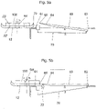
- FIGS 5a and 5b show a further exemplary embodiment of a detachment device 60.
- This detachment device 60 can be used when a grinding wheel 12 is arranged on the grinding wheel holder 100 in such a way that the grinding wheel 12 projects beyond the grinding wheel holder 100 at the periphery.
- the edge 72 of such a grinding wheel 12 can bend up so that it would come to rest above the separating edge 54 if the separating element 53 were used, as is shown in 4 is shown.
- a tiltable separating element 63 can be used. This is arranged in such a way that in the tilted state the separating edge 64 or at least its tip 65 is located slightly higher than the opposite end of the tiltable separating element 63.
- a tilting mechanism 70 is actuated, which tilts the separating edge 64 in the direction of the bearing surface 61, so that the angle of attack of the separating element 63 is reduced.
- the separating edge 64 grasps the edge 72 of the grinding wheel 12 and presses it in the direction of the bearing surface 61. Then the movement of the Grinding wheel holder 100 can be continued in the direction of arrow 71, which is Figure 5b is shown.
- the separating element 63 successively detaches the grinding wheel 12 from the grinding wheel mount 100 .
- a system comprises a device 1 for automatically changing grinding wheels 12, containing a stacking device 10 according to one of the preceding exemplary embodiments and a detaching device 50 according to one of the preceding exemplary embodiments.
Landscapes
- Engineering & Computer Science (AREA)
- Mechanical Engineering (AREA)
- Constituent Portions Of Griding Lathes, Driving, Sensing And Control (AREA)
- Finish Polishing, Edge Sharpening, And Grinding By Specific Grinding Devices (AREA)
Description
- Gegenstand der Erfindung ist eine Vorrichtung zum automatischen Wechsel von Schleifscheiben gemäss Oberbegriff des Patentanspruchs 1. Gegenstand der Erfindung ist ferner ein System umfassend eine Vorrichtung zum automatischen Wechsel von Schleifscheiben gemäss Anspruch 11.
- Eine automatische Schleifvorrichtung enthält einen Werkzeugkopf mit einer Aufnahmevorrichtung für eine Schleifscheibe. Diese Aufnahmevorrichtung ist beispielsweise als Schleifteller ausgebildet, der eine Klettverbindung enthält, die insbesondere als Velcro ®-Pad ausgebildet sein kann. Auf dem Schleifteller kann eine Schleifscheibe aufgelegt und durch den Kletterschluss am Schleifteller gehalten werden. Die Häkchen der Klettverbindung greifen hierbei in die filzartige Oberfläche der Schleifscheibe ein, sodass die Schleifscheibe durch die Klettverbindung am Werkzeug an der Oberfläche des Schleiftellers gehalten wird. Der Schleifteller kann eine Drehbewegung oder eine Exzenterbewegung ausführen, oder eine Kombination nach Art einer Taumelbewegung, sodass ein Polieren einer beliebig geformten Oberfläche eines Werkstücks mit dem Schleifwerkzeug erfolgen kann. Der Werkzeugkopf kann Bestandteil einer Manipulationsvorrichtung sein, beispielsweise kann der Werkzeugkopf an einem Manipulationsarm angebracht sein, insbesondere an einem Roboterarm.
- Roboterarme für diverse Anwendungen sind beispielsweise aus der
WO2015074089A1 bekannt. Ein derartiger Roboterarm besteht aus mehreren Armsegmenten, Dämpfungselementen zur Kopplung des ersten und zweiten Armsegments, einem Sensor zur Erfassung der Lage des ersten Armsegments in Bezug auf das zweite Armsegment sowie eine Steuereinheit, welche den Antriebsmotor für den Roboterarm in Abhängigkeit vom erhaltenen Sensorsignal ansteuert und den Roboterarm in eine Sollposition bewegt, wenn auf den Roboterarm keine Kraft wirkt. Ein derartiger Roboterarm wird beispielsweise zum Stapeln von Gegenständen verwendet, was in derWO2014205475A1 gezeigt ist. Wenn man derartige Gegenstände präzise positionieren möchte, muss der Gegenstand von einem Manipulator ergriffen und präzise bewegt werden, wozu gemässWO2014205475A1 ein Aktor verwendet wird, der zwischen dem Manipulator und dem zu positionierenden Gegenstand angeordnet ist. - Schleifscheiben müssen als Verschleissteile periodisch ausgewechselt werden. Eine Möglichkeit des Auswechselns der Schleifscheiben besteht darin, den Schleifvorgang zu unterbrechen, die Schleifvorrichtung abzustellen und die Schleifscheibe manuell auszutauschen, weil die Komplexität dieses Arbeitsablaufs nach den vorstehenden Ausführungen eine Automatisierung desselben als nicht wirtschaftlich erscheinen hat lassen.
- Ein möglicher Lösungsansatz besteht darin, die komplexen Manipulationsaufgaben in einfache Teilaufgaben zu zerlegen, sodass der Steuerungsaufwand für jede der Teilaufgaben verringert ist. Diesem Ansatz folgt die
DE 20 2013 101 858 U , die eine Anlage zum automatischen Auswechseln von Schleifscheiben offenbart. Der Wechsel der Schleifscheiben erfolgt in drei Stationen, die nacheinander vom Werkzeugarm des Roboters besucht werden, eine Ablösestation, eine Ausrichtstation und eine Beladestation. -
WO 2015/125068 A1 offenbart eine Vorrichtung zum automatischen Wechsel von Schleifscheiben, gemäß dem Oberbegriff von Anspruch 1. - Aus der
EP 1916062A1 ist ein Vorratsbehälter mit übereinander gestapelten und bezüglich der Absaugausnehmungen für Schleifstaub exakt ausgerichtete Schleifmittel bekannt. Die übereinander gestapelten Schleifmittel sind auf einem in einem Zylinder exakt vertikal geführten Teller angeordnet. Dieser ist weder dreh- noch in x- oder y-Richtung verschiebbar, so dass das Erfassen der einzelnen Schleifkörper mit einem Roboterarm nur in einer einzigen exakt voraus positionierten Lage möglich ist. Geringfügige Abweichungen der Lage des Roboterarms führen dazu, dass die Schleifscheiben nicht aufgenommen werden können. - Aus der
US 7,144,313 B1 ist weiter ein Stapelbehälter bekannt, mit darauf angeordneten exakt übereinander liegenden Schleifscheiben, welche paketweise einer automatisierten Schleifanlage vorgelegt werden können. Wie bei der erstgenannten Schrift sind auch hier die Schleifscheiben horizontal unbeweglich gehalten, weshalb das Erfassen durch einen Roboterarm mit höchster Präzision erfolgen muss. - Die Ablösestation ist als eine horizontale Unterlage ausgebildet, auf welche der Werkzeugkopf mit der auszuwechselnden Schleifscheibe abgestellt werden kann. Ein Schieber wird zwischen der Schleifscheibe und dem Werkzeugkopf positioniert und die Schleifscheibe mit dem Schieber gegen die Unterlage gedrückt. Wenn der Werkzeugkopf von der Ablösestation entfernt wird, wird die Schleifscheibe vom Schieber zurückgehalten. Danach wird der Schieber in seine Ausgangsstellung zurückgefahren und die Unterlage gekippt, sodass die gebrauchte Schleifscheibe entsorgt werden kann.
- Der Werkzeugkopf fährt anschliessend eine Ausrichtstation an, die dazu dient, den Werkzeugkopf in einer definierten Lage zu positionieren, sodass eine neue Schleifscheibe korrekt auf dem Werkzeugkopf positioniert werden kann. Hierzu enthält die Station Sensoren, welche die Sollposition der Absaugöffnungen am Werkzeugkopf erfassen und über eine Steuerung den Stellmotor des Werkzeugkopfs einschalten, um den Werkzeugkopf in die Sollposition zu bringen.
- Der Ausrichtstation ist eine Beladestation nachgeschaltet, welche einen Stapel von neuen Schleifscheiben enthält. Der ausgerichtete Werkzeugkopf kann präzise auf dem Stapel der Schleifscheiben positioniert werden, um die zuoberst liegende Schleifscheibe vom Stapel zu nehmen. Die Schleifscheibe bleibt in der korrekten Position haften, wobei unter korrekter Position eine Position zu verstehen ist, in welcher die Absaugöffnungen am Werkzeugkopf über den Öffnungen in der Schleifscheibe liegen.
- Diese Vorrichtung hat sich insofern als nachteilig erwiesen, als dass die Schleifscheibe während des Ablösens durch den Schieber beschädigt werden kann, wenn ihre Position relativ zur Ablösestation nicht präzise genug bestimmt ist. Um diesem Nachteil abzuhelfen, wurde eine Vorrichtung zum automatischen Wechsel von Schleifscheiben gemäss der
EP 2 842 689 B1 konzipiert. Eine derartige Vorrichtung weist ein Anschlagelement zur Abnahme einer Schleifscheibe von einem Schleifwerkzeug auf, an welches die Kopfplatte mit der Schleifscheibe in einer Abnahmeposition anlegbar ist, mindestens einen Abnahmefinger, welcher zwischen einer Rückzugsposition und einer Eingriffsposition verstellbar ist, sowie eine Spanneinrichtung, durch welche der Abnahmefinger relativ zum Anschlagelement verschiebbar ist. Mittels des Abnahmefingers kann die Schleifscheibe am Anschlagelement festgespannt werden. Der Abnahmefinger ist frei von scharfen Kanten, sodass eine Beschädigung der Schleifscheibe und demzufolge ein allfälliger Abbruch des Abnahmevorgangs durch unvollständig entfernte Schleifscheiben oder durch Blockierung der Abnahmevorrichtung vermieden wird. - Das Auswechseln der Schleifscheiben ist allerdings aufwändig, da das am Roboterarm geführte Schleifwerkzeug einen speziellen Aufsatz zum Abnehmen der Schleifscheiben aufweist. Dieser Aufsatz weist eine Mehrzahl von Ausnehmungen an dessen Umfang auf, in welche die Finger der Schleifscheibenabnahmevorrichtung eingreifen können. Hierzu ist es erforderlich, dass das am Roboterarm angebrachte Schleifwerkzeug mit der gebrauchten Schleifscheibe präzise auf der Schleifscheibenabnahmevorrichtung positioniert wird. Hierzu muss nicht nur die Mittenachse der Schleifscheibe mit der Mittenachse der Schleifscheibenaufnahmevorrichtung übereinstimmen, sondern auch der Winkel, in welchem die Schleifscheibe auf der Schleifscheibenaufnahmevorrichtung zu liegen kommt, muss exakt eingehalten werden. Wenn es zu Winkelabweichungen kommt, können die Finger der Schleifscheibenaufnahmevorrichtung die Schleifscheibe nicht mehr ergreifen, sodass die Abnahme der Schleifscheibe nicht erfolgen kann. Wenn die gebrauchte Schleifscheibe von den Fingern der Schleifscheibenaufnahmevorrichtung erfasst worden ist, kann sie vom Werkzeug abgenommen werden. Hierzu greifen die Finger der Schleifscheibenaufnahmevorrichtung in entsprechende Nuten auf der Schleifscheibenauflage des Werkzeugs ein. Das heisst aber, dass die Schleifscheibenauflage exakt entsprechend der Vorgaben der Schleifscheibenaufnahmevorrichtung gefertigt werden muss.
- Nach der Abnahme der gebrauchten Schleifscheibe wird das Werkzeug vom Roboterarm auf einem Schleifscheibenspender positioniert. Der Schleifscheibenspender oder die Stapelvorrichtung ist als ein zylinderförmiger Hohlraum ausgebildet, in welchem eine Mehrzahl von Schleifscheiben übereinander gestapelt ist. Der Innendurchmesser des Hohlraums ist etwas grösser als der Aussendurchmesser der Schleifscheiben. Die Schleifscheiben enthalten eine Mehrzahl von Löchern. Durch zwei dieser Löcher ist je ein Dorn hindurchgeführt, sodass die Schleifscheiben durch den entsprechenden Dorn in einer bestimmten Lage fixiert sind. Aus der vorhergehenden Beschreibung ist entnehmbar, dass das automatische Auswechseln von Schleifscheiben immer noch einen komplizierten Ablauf impliziert, der durch die zweimalige Ausrichtung des Werkzeugkopfs bei der Entnahme der Schleifscheibe sowie bei der Aufnahme einer neuen Schleifscheibe erfordert.
- Aufgabe der vorliegenden Erfindung besteht darin, eine Vorrichtung bereitzustellen, um den automatisierten Schleifscheibenwechsel zu vereinfachen.
- Insbesondere ist es Aufgabe der Erfindung, den die Schleifscheibenaufnahme des Schleifwerkzeugs und die Schleifscheibe auf vereinfachte Weise derart auszurichten, dass in der Schleifscheibenaufnahme angeordnete Absaugöffnungen für Schleifgut mit entsprechenden auf der Schleifscheibe angeordneten Öffnungen fluchten, sodass die Absaugung von Abrieb durch die Schleifscheibe nicht behindert wird.
- Gelöst wird diese Aufgabe durch eine Vorrichtung gemäss den Merkmalen des Patentanspruchs 1. Vorteilhafte Ausgestaltungen der Vorrichtung sind Gegenstand der abhängigen Ansprüche 2 bis 10.
- Eine Vorrichtung zum automatischen Wechsel von Schleifscheiben umfasst eine Stapelvorrichtung für eine Mehrzahl von Schleifscheiben, sowie ein Führungselement zur Ausrichtung der Schleifscheiben übereinander entlang einer gemeinsamen Mittenachse, wobei das Führungselement in Bezug auf die Mittenachse exzentrisch angeordnet ist. Ein Positionierelement zur Positionierung eines Werkzeugkopfs ist vorgesehen, wobei das Positionierelement und das Führungselement schwimmend gelagert sind. Das Positionierelement ist insbesondere entlang der Mittenachse angeordnet, sodass die Mittenachse der Längsachse des Positionierelements entspricht. Das Positionierelement ist insbesondere ein rotationssymmetrischer Körper, dessen Symmetrieachse die Mittenachse ist. Beispielsweise kann das Positionierelement als ein Zylinder ausgebildet sein.
- Der Vorteil dieser schwimmenden Lagerung liegt darin, dass die Positionierung des Werkzeugs auf dem Positionierelement sehr einfach erfolgen kann. Ein Loch im Werkzeug erfasst das in zentraler Lage angeordnete Positionierelement mit einem konischen oberen Ende und kann auf dieses aufgesetzt werden, selbst wenn das Werkzeug das Positionierelement nicht exakt mittig trifft, da die Position des Werkzeugkopfs mit der Schleifscheibenaufnahme über die schwimmende Lagerung ausgeglichen werden kann. Somit ergibt sich bei der Positionierung des Werkzeugkopfs mit der Schleifscheibenaufnahme auf dem Positionierelement der Stapelvorrichtung eine Zeitersparnis sowie verminderte Anforderungen betreffend die Präzision der Positionierung.
- Nach einem Ausführungsbeispiel ist ein Bodenelement zur Aufnahme des Positionierelements und des Führungselements vorgesehen. Insbesondere kann das Bodenelement ein schwingungsfähiges Element, beispielsweise mindestens ein Federelement, enthalten, durch welches eine Bewegung des Bodenelements in Radialrichtung in Bezug auf die Mittenachse ermöglicht ist. Das Bodenelement kann auch als Zwischenboden ausgebildet sein, der in einer Stapelvorrichtung angeordnet ist und von den federnden Elementen gehalten ist.
- Das Bodenelement kann in einem Gehäuse einer Stapelvorrichtung aufgehängt werden. Das schwingungsfähige Element kann auch ein elastisches Material enthalten, wobei das elastische Material in radialer Richtung reversibel dehnbar oder stauchbar sein kann.
- Unter radialer Richtung wird hierbei jede Auslenkung der Mittenachse in einer das Bodenelement enthaltenden Normalebene zur Mittenachse verstanden. Wenn die Schleifscheiben in der Stapelvorrichtung horizontal angeordnet sind, ist das Bodenelement ebenfalls horizontal angeordnet. Die Normalebene ist in diesem Fall eine Horizontalebene. Wenn in dieser Horizontalebene ein kartesisches Koordinatensystem derart angeordnet wird, dass die z-Achse der Mittenachse entspricht, können Bewegungen des Bodenelements in zumindest einer der x oder y-Achsen erfolgen.
- Das Positionierelement ist insbesondere in Richtung der Mittenachse axial bewegbar. Das Positionierelement kann als ein Stab ausgebildet sein, welcher im Bodenelement aufgenommen ist. Insbesondere kann das Positionierelement in einer Bohrung im Bodenelement aufgenommen sein, wobei in der Bohrung ein Abstandselement angeordnet ist. Das Abstandselement befindet sich somit am oder unterhalb des unteren Endes des Positionierelements. Das Positionierelement kann somit in axialer Richtung beim Kontakt mit einer Schleifscheibenaufnahme eines Werkzeugkopfs ausweichen, sodass ein sanfter Kontakt zwischen Positionierelement und Schleifscheibenteller erfolgt. Hierdurch können Schäden an der Schleifscheibenaufnahme bei der Positionsfindung vermieden werden, da beim Kontakt mit dem Positionierelement keine schädlichen Kräfte in die Schleifscheibenaufnahme eingeleitet werden. Das Abstandselement kann mindestens ein Element der Gruppe der Federelemente, der elastischen Elemente oder der magnetisierbaren Elemente enthalten.
- Nach einem Ausführungsbeispiel weist das Positionierelement eine grössere Höhe als das Führungselement auf. Hierdurch wird sichergestellt, dass während des Positioniervorgangs zur Festlegung der radialen Position die Schleifscheibenaufnahme durch das Positionierelement und nicht durch die Führungselemente berührt wird. Das heisst, die Mittenachse der Schleifscheibenaufnahme wird in Übereinstimmung mit der Mittenachse der Stapelvorrichtung gebracht. Die Schleifscheibenaufnahme ist frei beweglich, um eine Taumelbewegung während des Schleifvorgangs ausüben zu können. Durch diese freie Beweglichkeit in Drehrichtung ist aber der genaue Aufenthaltsort der Schleifscheibe bzw. von deren zentral angeordneten Öffnung nicht bekannt, bis die Schleifscheibenaufnahme auf dem Positionierelement aufgenommen ist. Sobald das obere Ende des Positionierelements in die Schleifscheibenaufnahme eingreift, ist die axiale Ausrichtung der Schleifscheibenaufnahme in Bezug auf die Mittenachse der Schleifscheiben bzw. des Positionierelements vorgegeben.
- Daher muss nur noch die radiale Position der Schleifscheibenaufnahme in Bezug auf die Schleifscheibe gefunden werden. Das Führungselement verläuft durch eine der exzentrisch zur zentralen Öffnung angeordneten Öffnungen, die in der Schleifscheibe vorgesehen sind, um das Absaugen von Abrieb im Betrieb zu ermöglichen.
- Das Positionierelement ist nach einem Ausführungsbeispiel als ein Stab ausgebildet, wobei das Positionierelement ein unteres Ende aufweist, welches in der Bohrung aufgenommen ist und ein oberes Ende aufweist, welches über die zuoberst angeordnete Schleifscheibe hinausragt, wobei das obere Ende insbesondere einen konischen Abschnitt umfasst. Die Schleifscheibenaufnahme befindet somit in dieser Stellung, in welcher sie auf dem konischen Abschnitt angeordnet ist, d.h. noch nicht in Kontakt mit dem Führungselement. Daher ist die Schleifscheibenaufnahme um das Positionierelement frei drehbar, sodass die korrekte Position der Schleifscheibe in Bezug auf die Schleifscheibenaufnahme in einer nachfolgenden radialen Justierung eingestellt werden kann.
- Für die Justierung in Umfangsrichtung muss die Schleifscheibenaufnahme in einer Position über der Schleifscheibe zu liegen kommen, in welcher die Öffnungen der Schleifscheibe mit den Ausnehmungen der Schleifscheibenaufnahme fluchten, wenn die korrekte Position erreicht ist. Nach einem Ausführungsbeispiel kann diese Position mittels einer Erkennungsvorrichtung gefunden werden. Diese Position kann beispielsweise mittels eines einzigen Sensors gefunden werden. Der Sensor kann ein Sensor sein, wie er in der
DE 20 2013 101 858 U1 oder derEP 2 842 689 B1 beschrieben ist, sein. Allerdings wird nur ein einziger Sensor benötigt, da nur die Winkelposition der Ausnehmung der Schleifscheibenaufnahme in Bezug auf die Öffnung in der Schleifscheibe festgelegt werden muss. Sobald der Sensor eine Ausnehmung detektiert, erfolgt die Anweisung an die Steuerung des Werkzeugkopfs, den Werkzeugkopf und damit die Schleifscheibenaufnahme in die Position zu drehen, in welcher die Öffnung in der Schleifscheibe und die Ausnehmung an der Schleifscheibenaufnahme fluchten. - Für diese Justierung kann nach einem weiteren Ausführungsbeispiel die Schleifscheibenaufnahme mittels eines Antriebselements in Drehung versetzt werden. Das Antriebselement kann beispielsweise eine Düse enthalten, mittels welchem ein Druckfluidstrahl erzeugbar ist. Beispielsweise kann der Druckfluidstrahl ein Druckluftstrahl sein, es können aber auch andere Fluide, insbesondere Gase verwendet werden.
- Das Antriebselement könnte jede beliebige andere, dem Fachmann geläufige Bauweise aufweisen, um eine Drehbewegung der Schleifscheibenaufnahme zu bewirken. Beispielsweise könnte die Schleifscheibenaufnahme mit dem Antriebselement kraftschlüssig oder reibschlüssig verbindbar sein. Die Schleifscheibenaufnahme kann beispielsweise einen Zahnkranz aufweisen, der mit einem Antriebsritzel koppelbar ist. Alternativ oder in Ergänzung hierzu kann das Antriebselement einen Magneten oder ein magnetisierbares Material enthalten, welches mit einem entsprechenden Gegenelement an der Schleifscheibenaufnahme koppelbar sein kann.
- Gemäss eines Ausführungsbeispiels dient das als Düse ausgebildete Antriebselement dazu, einen Druckfluidstrahl auf die Schleifscheibenaufnahme zu lenken, um die Schleifscheibenaufnahme in eine Drehbewegung zu versetzen. Die Drehgeschwindigkeit der Drehbewegung und/oder die gewünschte Distanz können durch die Zeitdauer und/oder Intensität des Druckfluidstrahls eingestellt werden. Beispielsweise kann ein Druckfluidimpuls mit einer Zeitdauer von vorzugsweise maximal 1 sec auf die Schleifscheibenaufnahme aufgebracht werden, sodass die Schleifscheibenaufnahme in eine Drehbewegung versetzbar ist. Die Drehbewegung ist derart regelbar, dass die Schleifscheibenaufnahme in einer Position über der Schleifscheibe zu liegen kommt, in welcher die Öffnungen der Schleifscheibe mit den Ausnehmungen der Schleifscheibenaufnahme fluchten, wenn die korrekte Position erreicht ist.
- Diese Position kann wie im vorhergehenden Ausführungsbeispiel mittels einer Erkennungsvorrichtung gefunden werden, beispielsweise mittels eines einzigen Sensors. Das Antriebselement weist eine Steuerung auf, mittels welcher die korrekte Position der Schleifscheibenaufnahme ermittelt werden kann. Das Antriebselement kann beispielsweise, wie vorgehend beschrieben, eine Drehbewegung der Schleifscheibenaufnahme einleiten. Dieses Antriebselement muss sich somit nicht im Werkzeugkopf befinden, womit die Bauweise des Werkzeugkopfs vereinfacht werden kann, da der Werkzeugkopf keinen Antrieb benötigt, der zur Justierung der Schleifscheibenaufnahme geeignet ist.
- Alternativ oder in Ergänzung hierzu kann die Intensität des Druckfluidstrahls geregelt werden. Beispielsweise kann über eine Änderung des Durchflussquerschnitts der Düsenöffnung die Austrittsgeschwindigkeit des Druckfluids verändert werden, sodass die Schleifscheibenaufnahme durch Regelung des Antriebselements in die von der Erkennungsvorrichtung vorgegebene Position bewegt werden kann.
- Nach einem Ausführungsbeispiel ist die Stapelvorrichtung in einem Behälter aufgenommen. Der Behälter enthält einen Behälterboden und einen Behälterdeckel mit einer Öffnung, durch welche jeweils eine der Schleifscheiben entnehmbar ist. Nach einem Ausführungsbeispiel ist der Durchmesser der Öffnung grösser als der Durchmesser der Schleifscheibe.
- Insbesondere kann ein Rückhalteelement vorgesehen sein, welches in die Öffnung hineinragt. Nach einem Ausführungsbeispiel kann eine Mehrzahl von derartigen Rückhalteelementen vorgesehen sein. Die Rückhalteelemente können verschiebbar sein, sodass sie von einer Halteposition in eine Entnahmeposition verstellbar sind. Beispielsweise können sie während der Zeit, während derer die Schleifscheibe auf der Schleifscheibenaufnahme positioniert wird, die Öffnung zumindest teilweise freigeben, sodass die Schleifscheibe leichter entnommen werden kann. Sobald die Schleifscheibe auf der Schleifscheibenaufnahme positioniert ist, wird das Rückhalteelement wieder in die Halteposition gebracht, sodass der Stapel von Schleifscheiben in der Öffnung gehalten wird.
- Der Stapel von Schleifscheiben kann von einem Auflageelement gehalten sein, welches mittels eines Spannelements in Bezug auf das Führungselement und das Positionierelement verschiebbar ist. Das Spannelement kann als Federelement ausgebildet sein. Das Federelement kann zwischen dem Zwischenboden und dem Auflageelement angeordnet sein.
- Nach einem weiteren Ausführungsbeispiel kann das Auflageelement mittels eines Hubelements geführt werden. Das Hubelement ermöglicht eine schrittweise Verstellung des Auflageelements, sodass nach Abnahme einer Schleifscheibe die darunterliegende Schleifscheibe an deren Position nachrückt. Das Hubelement kann ein Fluidzylinder, ein Elektromotor, federbelastete Rastelemente oder dergleichen enthalten.
- Ein Hubelement zum schrittweisen Nachführen der Schleifscheiben kann insbesondere zum Einsatz kommen, wenn formstabile Schleifscheiben zum Einsatz kommen. Unter einer formstabilen Schleifscheibe wird eine Schleifscheibe verstanden, die sich nur unter Krafteinwirkung verformt, welche mindestens das Doppelte des Eigengewichts der Schleifscheibe beträgt.
- Im Gegensatz dazu wird unter einer flexiblen Schleifscheibe eine Schleifscheibe verstanden, die sich bereits unter Einwirkung ihres Eigengewichts verformen kann. Eine derartige Schleifscheibe kann beispielsweise ein Schleifpapier oder einen Polierlappen, beispielsweise aus Leder oder einem textilen Werkstoff, umfassen.
- Nach einem weiteren Ausführungsbeispiel kann die Schleifscheibenaufnahme vom Antriebselement in eine Drehbewegung versetzt werden, wobei diese Drehbewegung im Unterschied zu den vorhergehenden Ausführungsbeispielen nicht geregelt zu werden braucht.
- Nach einem Ausführungsbeispiel kann das Führungselement mittels eines Betätigungselements axial verschiebbar sein.
- Die sich drehende Schleifscheibenaufnahme wird zur Justierung soweit in Richtung auf die Schleifscheibe hin bewegt, bis das Führungselement die Oberfläche der Schleifscheibe berührt. Das Führungselement ist in axialer Richtung verschiebbar. Insbesondere kann das Führungselement ein Betätigungselement enthalten, welches in der Bohrung angeordnet ist. Dieses Betätigungselement kann als Spannelement ausgebildet sein. Das Spannelement wird vorgespannt, wenn die Schleifscheibenaufnahme auf das Führungselement drückt. Insbesondere kann das Spannelement eine Feder umfassen. Das Spannelement des Führungselements wird dadurch geringfügig komprimiert, sodass das obere Ende des Führungselements einen geringen Anpressdruck auf die Schleifscheibenaufnahme ausübt. Sobald das obere Ende des Führungselements eine Ausnehmung in der Schleifscheibenaufnahme vorfindet, kann sich das Spannelement wieder entspannen. Das schleifscheibenaufnahmeseitige Ende des Führungselements gelangt in Eingriff mit der Ausnehmung, wodurch die Drehbewegung der Schleifscheibenaufnahme gestoppt wird. Die korrekte Position der Schleifscheibenaufnahme ist erreicht. Die Schleifscheibenaufnahme kann nunmehr in Richtung zur Schleifscheibe hin bewegt werden, um die Schleifscheibe vom Schleifscheibenstapel aufzunehmen.
- Das Betätigungselement kann auch ein magnetisierbares Element umfassen, welches am oberen Ende des Führungselements angebracht ist. Zu diesem magnetisierbaren Element kann ein magnetisierbares Gegenelement in der Bohrung angeordnet sein, wobei sich das magnetisierbare Element des oberen Endes des Führungselements und des magnetisierbaren Gegenelements in der Bohrung abstossen. Wird nun das Führungselement durch den Anpressdruck der Schleifscheibenaufnahme in die Bohrung verschoben erhöht sich die magnetische Abstossungskraft. Sobald sich das obere Ende des Führungselements in einer Ausnehmung befindet, bewegt sich das Führungselement durch die abstossenden Kräfte aus der Bohrung wieder hinaus und gelangt in Eingriff mit der Ausnehmung der Schleifscheibenaufnahme, wodurch deren Drehbewegung gestoppt wird. Die korrekte Position der Schleifscheibenaufnahme ist erreicht. Die Schleifscheibenaufnahme kann nunmehr in Richtung zur Schleifscheibe hin bewegt werden, um die Schleifscheibe vom Schleifscheibenstapel aufzunehmen.
- Nach jedem der vorhergehenden Ausführungsbeispiele kann eine Mehrzahl von Führungselementen vorgesehen sein. Insbesondere können zwei oder mehr Führungselemente vorgesehen sein, um die Kraft, die beim Unterbrechen der Drehbewegung auf das Führungselement wirkt, auf zwei oder mehr Führungselemente zu verteilen, sodass jedes Führungselement nur noch den entsprechenden Bruchteil der Kraft aufnehmen muss.
- Anstelle eines Spannelements oder zusätzlich zu dem Spannelement kann das obere Ende des Führungselements oben ein magnetisierbares Element enthalten, insbesondere kann das obere Ende einen Magneten enthalten. Dieser Magnet kann von einem entsprechenden magnetisierbaren Gegenelement in der Schleifscheibenaufnahme angezogen werden, wenn die Schleifscheibenaufnahme mit dem Positionierelement in Eingriff ist und während der Drehung eine Ausnehmung über dem magnetisierbaren Endelement zu liegen kommt. Das magnetisierbare Element kann insbesondere in der Ausnehmung der Schleifscheibenaufnahme enthalten sein.
- Insbesondere ist es Aufgabe der Erfindung, eine gebrauchte Schleifscheibe von einer Schleifscheibenaufnahme einfach abzulösen, wobei die Vorrichtung zum Ablösen der Schleifscheibe keine beweglichen Teile aufweisen soll.
- Gelöst wird diese Aufgabe durch eine Vorrichtung gemäss den Merkmalen des Patentanspruchs 9. Vorteilhafte Ausgestaltungen der Vorrichtung sind Gegenstand des abhängigen Anspruchs 10.
- Eine Vorrichtung zum automatischen Wechsel von Schleifscheiben, umfasst eine Ablösevorrichtung für Schleifscheiben, wobei die Ablösevorrichtung eine Auflagefläche für eine Schleifscheibenaufnahme umfasst. Die Auflagefläche weist eine Öffnung auf, deren Durchmesser grösser als der Durchmesser der Schleifscheibe ist. Ein Trennelement ist oberhalb der Öffnung angeordnet. Das Trennelement kann die Öffnung teilweise abdecken, sodass die Schleifscheibenaufnahme nicht in die Öffnung gelangen kann.
- Insbesondere kann das Trennelement eine Trennkante aufweisen, wobei die Trennkante eine Spitze umfassen kann. Für die Trennkante kann auch eine Mehrzahl von Spitzen vorgesehen sein. Nach einem Ausführungsbeispiel kann eine v-förmige Spitze vorgesehen sein. Nach einem Ausführungsbeispiel kann eine Spitze verwendet werden, deren Kanten asymmetrisch verlaufen, beispielsweise in der Form einer Guillotine. Nach einem Ausführungsbeispiel kann eine w-förmige Spitze verwendet werden. Eine w-förmige Spitze kann zwei Spitzenelemente aufweisen. Nach einem Ausführungsbeispiel kann ein gezacktes Profil, enthaltend eine Mehrzahl von Spitzen vorgesehen sein.
- Das Trennelement kann Rippen aufweisen, welche insbesondere in Bewegungsrichtung der Schleifscheibenaufnahme ausgerichtet sind. Diese Rippen können die Formstabilität erhöhen oder den Ablösevorgang der Schleifscheibe von der Schleifscheibenaufnahme unterstützen. Die Rippen können sich nur auf einer Seite des Trennelements befinden, sie können auch beidseitig angeordnet sein.
- Das Trennelement kann als eine Scheibe ausgebildet sein, welche zumindest entlang der Trennkante eine Wandstärke aufweist, die kleiner als der Abstand der Schleifscheibe von der Schleifscheibenaufnahme ist. Beispielsweise kann das Trennelement als ein dünnwandiges Blech ausgebildet sein.
- Nach einem Ausführungsbeispiel ist das Trennelement mittels Verbindungsmitteln auf der Auflagefläche lösbar befestigt. Das Trennelement kann von der Auflagefläche abgenommen werden, beispielweise um es durch ein Trennelement anderer Konfiguration zu ersetzen. Somit kann die Ablösevorrichtung für eine Vielzahl verschiedener Schleifscheiben zum Einsatz kommen.
- Ein Distanzelement kann zwischen dem Trennelement und der Auflagefläche vorgesehen sein. Mittels des Distanzelements kann der Abstand des Trennelements von der Auflagefläche eingestellt werden. Die Verwendung eines Distanzelements ermöglicht es, die Vorrichtung für unterschiedliche Typen von Schleifscheiben zu verwenden.
- Beispielsweise kann eine Schleifscheibe derart auf der Schleifscheibenaufnahme angeordnet sein, dass die Schleifscheibe die Schleifscheibenaufnahme radial überragt. Der Rand einer derartigen Schleifscheibe kann sich aufbiegen, sodass der Rand oberhalb der Trennkante zu liegen kommt.
- In diesem Fall kann ein kippbares Trennelement verwendet werden. Das kippbare Trennelement ist derart angeordnet, dass im gekippten Zustand die Trennkante oder zumindest deren Spitze etwas höher gelegen ist, als das gegenüberliegende Ende des Trennelements. Wenn der Rand einer Schleifscheibenaufnahme die Trennkante erreicht, wird an dieser Stelle durch die Schleifscheibenaufnahme ein Kippmechanismus betätigt, der die Trennkante in Richtung der Auflagefläche kippt, sodass sich der Anstellwinkel des Trennelements verringern kann.
- Durch die Änderung des Winkels erfasst die Trennkante den Rand der Schleifscheibe und drückt ihn in Richtung der Auflagefläche. Dann kann die Bewegung der Schleifscheibenaufnahme fortgesetzt werden. Das Trennelement kann die Schleifscheibe sukzessive von der Schleifscheibenaufnahme entfernen.
- Nach einem Ausführungsbeispiel kann das Trennelement mehr als eine Trennkante aufweisen. Die Trennkanten können insbesondere an mehr als einer Seitenkante des Trennelements angeordnet sein. Insbesondere kann eine derartige Ablösevorrichtung für zwei oder mehrere verschiedene Typen von Schleifscheiben gleichzeitig benutzt werden.
- Wenn eine Schleifscheibe mittels einer Klettverbindung auf einer Schleifscheibenaufnahme gehalten ist, ergibt sich funktionsbedingt ein Abstand zwischen der Schleifscheibe und der Schleifscheibenaufnahme, welche durch die Eingriffselemente der Klettverbindung bedingt ist, die untereinander verhaken.
- Die Wandstärke des Trennelements an der Trennkante ist daher vorzugsweise geringer als 5 mm, insbesondere weist die Wandstärke einen maximalen Wert im Bereich von 1 mm auf.
- Das Trennelement kann ein Ablenkelement enthalten, welches das Ablösen der Schleifscheibe unterstützen kann.
- Ein Verfahren zum Ablösen einer Schleifscheibe von einer Schleifscheibenaufnahme umfasst die folgenden Schritte: die Schleifscheibenaufnahme wird über die gezeigte Auflagefläche der Ablösevorrichtung geführt, wobei die Schleifscheibenaufnahme in Kontakt mit der Auflagefläche steht. Hierbei wird die Schleifscheibe vom Trennelement erfasst, das als ein Scheibenelement mit einer Trennkante der Schleifscheibenaufnahme über die Trennkante zwischen die Schleifscheibe und die Auflagefläche eingeschoben, wodurch die Schleifscheibe von der Schleifscheibenaufnahme abgelöst wird. Die Schleifscheibe fällt in eine unterhalb der Trennkante befindliche Öffnung.
- Die gebrauchten Schleifscheiben können in einem unterhalb der Öffnung angeordneten Sammelbehälter gesammelt werden und fachgerecht entsorgt werden.
- Insbesondere kann mit der erfindungsgemässen Lösung auf eine eigene Ausrichtstation für eine exakte Positionierung des Werkzeugkopfs zur Aufnahme einer neuen Schleifscheibe verzichtet werden, da die Positionierung unmittelbar vor Aufnahme einer neuen Schleifscheibe erfolgt.
- Insbesondere kann die Vorrichtung für formstabile und/oder flexible Schleifscheiben zum Einsatz kommen.
- Ein System umfasst eine Vorrichtung zum automatischen Wechsel von Schleifscheiben enthaltend eine Stapelvorrichtung nach einem der vorhergehenden Ausführungsbeispiele sowie eine Ablösevorrichtung nach einem der vorhergehenden Ausführungsbeispiele.
- Anhand eines illustrierten Ausführungsbeispiels wird die Erfindung näher erläutert. Es zeigen
- Figur 1
- eine Ansicht eine Ansicht der Stapelvorrichtung für Schleifscheiben; ohne Schleifscheiben,
- Figur 2
- einen Vertikalschnitt durch die Stapelvorrichtung für die Schleifscheiben gemäss
Fig. 1 , - Figur 3
- einen Vertikalschnitt durch eine Variante der Stapelvorrichtung für Schleifscheiben gemäss
Fig. 1 , - Figur 4
- eine perspektivische Ansicht einer Ablösevorrichtung für gebrauchte Schleifscheiben,
- Figur 5a
- einen Vertikalschnitt durch ein weiteres Ausführungsbeispiel für eine Ablösevorrichtung,
- Figur 5b
- einen Vertikalschnitt durch die Ablösevorrichtung gemäss
Fig. 5a zu Beginn des Ablösevorgangs - Die Vorrichtung 1 gemäss
Fig. 1 zum automatischen Wechsel von Schleifscheiben umfasst eine Stapelvorrichtung 10 enthaltend eine Mehrzahl von Schleifscheiben 12, sowie ein Führungselement 16 zur Ausrichtung der Schleifscheiben 12 übereinander entlang einer gemeinsamen Mittenachse, wobei das Führungselement 16 in Bezug auf die Mittenachse exzentrisch angeordnet ist. Ein Positionierelement 17 ist zur Positionierung einer Schleifscheibenaufnahme vorgesehen, wobei das Positionierelement 17 und das Führungselement 16 schwimmend gelagert sind. - Gemäss
Fig. 1 ist die Stapelvorrichtung 10 in einem Behälter 11 aufgenommen. Der Behälter 11 hat einen Behälterboden 13 und einen Behälterdeckel 14 mit einer Öffnung 15, durch welche jeweils eine der Schleifscheiben 12 entnehmbar ist. Der Durchmesser der Öffnung 15 ist grösser als der Durchmesser der Schleifscheibe 12. Es sind drei Rückhaltelemente 25 vorgesehen, welche in die Öffnung 15 hineinragen und die Schleifscheiben 12 in der Stapelvorrichtung 10 zu halten. Nach einer nicht dargestellten Variante ragen das oder die Rückhalteelemente 25 nicht in die Öffnung. - Durch die Schleifscheiben 12 sind ein Positionierelement 17 sowie drei Führungselemente 16 hindurchgeführt, deren obere Enden in
Fig. 1 sichtbar sind. Die Schleifscheiben 12 weisen hierzu entsprechende Öffnungen auf, eine zentrale Öffnung für das Positionierelement 17 sowie in der vorliegenden Darstellung sechs Öffnungen 32. Drei dieser Öffnungen 32 enthalten ein Führungselement 16. - In
Fig. 2 ist ein Ausschnitt eines Schnitts durch die Stapelvorrichtung 10 gemässFig. 1 gezeigt, welcher in einer die Mittenachse 18 des Positionierelements 17 enthaltenden Ebene verläuft. In der Schnittdarstellung ist der Behälter 11 weggelassen, um die Darstellung nicht zu überladen. - Ein Bodenelement 20 ist zur Aufnahme des Positionierelements 17 und des Führungselements 16 im Behälter 11 vorgesehen. Das Bodenelement 20 enthält ein schwingungsfähiges Element 19, z.B. eine Schraubenfeder, durch welches eine Bewegung des Bodenelements 20 in Radialrichtung in Bezug auf die Mittenachse 18 ermöglicht ist. Das Bodenelement 20 kann einen Zwischenboden im Behälter 11 ausbilden, der oberhalb des in
Fig. 1 dargestellten Behälterbodens 13 verläuft. - Das Positionierelement 17 weist eine grössere Höhe als das Führungselement 16 auf. Hierdurch ist gewährleistet, dass eine Schleifscheibenaufnahme 100, auch Schleifteller genannt, die an einem Werkzeugkopf angeordnet sein kann, zuerst mit dem Positionierelement 16 in Eingriff gelangt, bevor sie die schleifscheibenauflageseitigen Enden der Führungselemente 16 berührt. Der Werkzeugkopf enthält als Schleifscheibenaufnahme beispielsweise einen frei drehbaren Schleifteller, welcher zur Durchführung eines Schleifverfahrens eine Schleifscheibe 12 trägt.
- Die Schleifscheibenaufnahme kann insbesondere eine kombinierte Dreh- und Verschiebebewegung ausführen, was in einer Taumelbewegung resultiert. Eine derartige Schleifscheibenaufnahme 100 ist aus dem Stand der Technik bekannt und wird daher nicht dargestellt. Aufgrund dieser Taumelbewegung ist die Position der Schleifscheibenaufnahme 100 in Bezug auf die Mittenachse 18 nicht bekannt, wenn sich eine Schleifscheibenaufnahme 100 der Stapelvorrichtung 10 nähert, um mit einer neuen Schleifscheibe 12 bestückt zu werden.
- Um eine Schleifscheibe 12 an der Schleifscheibenaufnahme korrekt zu positionieren, muss die Schleifscheibe 12 nicht nur mittig auf der Schleifscheibenaufnahme 100 positioniert werden, sondern die Öffnungen 32 an der Schleifscheibe 12 müssen mit Ausnehmungen 33 der Schleifscheibenaufnahme 100 fluchten. Diese Ausnehmungen 33 dienen der Absaugung von Abrieb, der beim Schleifprozess anfällt. Der Abrieb kann beispielsweise Schleifpartikel, Kühlmittel, Reinigungsmittel umfassen.
- Die Schleifscheibenaufnahme muss daher bei jedem Wechsel der Schleifscheibe 12 in Bezug auf die in der Stapelvorrichtung 10 befindlichen Schleifscheiben 12 positioniert und justiert werden. Unter Positionierung wird dabei ein Arbeitsschritt verstanden, welcher die Mittenachse der Schleifscheibenaufnahme 100 mit der Mittenachse 18 in Übereinstimmung bringt.
- Unter Justierung wird ein Arbeitsschritt verstanden, welcher die Öffnungen 32 der Schleifscheibe 12 mit den Ausnehmungen der Schleifscheibenaufnahme 100 in Übereinstimmung bringt.
- Zur Positionierung wird daher die Schleifscheibenaufnahme 100 über das freie Ende 28 des Positionierelements 17 geführt, wobei die genaue Position der Mittenachse 18 des Positionselements 17 nicht genau bekannt ist, weil die Schleifscheibenaufnahme 100 bekanntlich eine taumelnde Bewegung ausführt. In der Schleifscheibenaufnahme 100 ist eine zylindrische Bohrung 101 ausgebildet, deren Durchmesser D grösser ist, als das obere konisch verlaufende Ende 28 des Positionierelements 17.
- Da das Bodenelement 20 als ein schwingungsfähiges Element 19 ausgebildet ist, welches eine Bewegung des Positionierelements 17 mit dem Bodenelement 20 in Radialrichtung in Bezug auf die Mittenachse 18 ermöglicht, kann das Positionierelement 17 dank seinem konisch zulaufenden freien oberen Ende 28 in das zentrale Loch in der Schleifscheibe 12 eingreifen und sich bezüglich der zentralen Bohrung 101 in der Schleifscheibenaufnahme 100 zentrieren.
- Das Positionierelement 17 ist axial in Richtung der Mittenachse 18 bewegbar. Das Positionierelement 17 ist als Stab ausgebildet, welcher mit seinem unteren Ende 29 in einer Bohrung 21 im Bodenelement 20 teilweise aufgenommen ist. In der Bohrung 21 ist ein Abstandselement 22 angeordnet, welches als Feder dargestellt ist.
- Sobald die Schleifscheibenaufnahme 100 mit dem Positionierelement 17 in Eingriff gelangt und weiter nach unten geführt wird, wird der Translationsanteil der Taumelbewegung in die Lagerung eingeleitet. Das schwingungsfähige Element 19 fängt diese Taumelbewegung ab und kann sie entsprechend ausgleichen. Daher kann die Schleifscheibenaufnahme nur eine Drehbewegung um die Mittenachse 18 des Positionierelements 17 ausführen, sobald das freie Ende 28 des Positionierelements 17 mit der Bohrung 101 in der Schleifscheibenaufnahme 100 im Eingriff ist. Deshalb weist die Schleifscheibenaufnahme 100 die zentrale Bohrung 101 auf, deren Durchmesser einem Durchmesser des konischen Abschnitts des freien Endes 28 des Positionierelements 17 entspricht oder der etwas grösser als der Durchmesser des Positionierelements 17 ist.
- Die Drehbewegung der Schleifscheibenaufnahme 100 kann durch ein Antriebselement 30 initiiert oder verstärkt werden, welches in
Fig. 1 dargestellt ist. Das Antriebselement 30 umfasst eine Düse, wobei durch die Düse ein Druckfluidstrahl auf die Schleifscheibenaufnahme 100 gerichtet werden kann. Mittels des Druckfluidstrahls wird die Schleifscheibenaufnahme 100 in eine Drehbewegung versetzt. - Sobald die Schleifscheibenaufnahme 100 eine Drehbewegung ausführt, kann der Arbeitsschritt des Justierens durchgeführt werden. Hierzu wird die Schleifscheibenaufnahme 100 entlang der Mittenachse 18 weiter nach unten in Richtung der neuen Schleifscheibe 12 bewegt. Während dieser Bewegung wird das Positionierelement 17 in die Bohrung 21 gegen die Federkraft des Abstandselements 22 hineinbewegt.
- Wenn die Schleifscheibenaufnahme 100 das obere freie Ende des oder der Führungselemente 16 erreicht, wird auch das Führungselement 16 bzw. werden sämtliche Führungselemente 16 in Richtung des Bodenelements 20 verschoben. Das untere Ende des Führungselements 16 wird in eine Führungsbohrung 24 hineinverschoben. Zwischen dem bodenelementseitigen Ende des Führungselements 16 und dem Bohrungsgrund der Führungsbohrung 24 ist ein Federelement 23 angeordnet.
- Das obere Ende des Führungselements 16 ist in Kontakt mit der sich drehenden Schleifscheibenaufnahme 100. Sobald das obere Ende des Führungselements 16 auf die Bohrung 101 in der Schleifscheibenaufnahme trifft, wird das Führungselement 16 aus der Führungsbohrung 24 ein Stück hinausgedrängt. Das obere Ende des Führungselements 16 gelangt in Eingriff mit der Bohrung 101 der Schleifscheibenaufnahme 100 und blockiert diese, sodass eine weitere Drehbewegung unterbunden wird. In dieser Position fluchten die Öffnungen 32 der Schleifscheibe 12 exakt mit den Ausnehmungen 33 der Schleifscheibenaufnahme 100. Somit ist die Schleifscheibenaufnahme 100 korrekt positioniert, um eine Schleifscheibe 12 aufzunehmen.
- Hierzu wird die Schleifscheibenaufnahme 100 weiter nach unten in Richtung der neuen Schleifscheibe 12 abgesenkt.
- Der Öffnung 15 ist jeweils eine der Schleifscheiben 12 entnehmbar. Der Durchmesser der Öffnung 15 ist grösser als der Durchmesser der Schleifscheibe 12. Daher ist eines der drei Rückhalteelemente 25 gezeigt, welches in die Öffnung 15 hineinragt, um die Schleifscheiben 12 in der Stapelvorrichtung 10 zu halten.
- Der Stapel von Schleifscheiben 12 ist von einem Auflageelement 26, z.B. eine Scheibe oder Platte, getragen, welches mittels eines Spannelements 27 in Gestalt einer Feder entlang der Achsen des Führungselements 16 und der Mittenachse 18 des Positionierelements 17 verschiebbar ist. Das Spannelement 27 stützt sich auf der Oberfläche des Bodenelements 20 ab.
- Die Schleifscheibenaufnahme 100 wird soweit abgesenkt, bis sie in Kontakt mit der Schleifscheibe 12 kommt. Die Schleifscheibe 12 haftet auf der Oberfläche der Schleifscheibenaufnahme 100, sei es durch Applikation eines Unterdrucks, um die Schleifscheibe 12 anzusaugen, sei es mittels einer Klettverbindung oder einer Kombination verschiedener Haltemechanismen. Die Schleifscheibenaufnahme 100 mit der Schleifscheibe 12 wird anschliessend von der Stapelvorrichtung wegbewegt und ist bereit für einen neuen Einsatz.
- Wenn die Schleifscheibe 12 flexibel ist, wird sie an den Rückhalteelementen 25 vorbei gezogen. Wenn die Schleifscheibe 12 als eine formstabile Schleifscheibe ausgebildet ist, können die Rückhalteelemente 25 einstellbar sein. Beispielsweise können sie aufklappbar oder nach aussen verschiebbar sein, sodass die Schleifscheibe 12 die Öffnung ungehindert passieren kann.
-
Fig. 3 zeigt eine Variante derFig. 2 gemäss welcher ein Hubelement 40 für das Nachführen der Schleifscheiben 12 des Schleifscheibenstapels vorgesehen ist. -
Fig. 4 zeigt eine Ansicht einer Ablösevorrichtung 50. Die Ablösevorrichtung 50 dient der Entfernung einer Schleifscheibe 12 von einer Schleifscheibenaufnahme 100 vor dem Scheibenwechsel. Eine Vorrichtung 1 zum automatischen Wechsel von Schleifscheiben 12 kann eine solche Ablösevorrichtung 50 umfassen. Bevor eine neue Schleifscheibe 12 auf der Schleifscheibenaufnahme 100 positioniert werden kann, muss die verschlissene oder gebrauchte Schleifscheibe 12 von der Schleifscheibenaufnahme 100 getrennt werden. - Die Ablösevorrichtung 50 umfasst eine Auflagefläche 51. Die Auflagefläche 51 weist eine Öffnung 52 auf, deren Durchmesser grösser als der Durchmesser der Schleifscheibe 12 ist. Ein Trennelement 53 ist oberhalb der Öffnung 52 angeordnet. Das Trennelement 53 erstreckt sich teilweise über die Öffnung 52, sodass die Schleifscheibenaufnahme 100 nicht in die Öffnung 52 eintauchen kann.
- Das Trennelement 53 weist mindestens eine Trennkante 54 auf. Die Trennkante 54 umfasst eine Spitze 55, die radial in Richtung des Randes der Öffnung 52 zeigt. Die Spitze 55 kann v-förmig oder w-förmig oder mit asymmetrisch verlaufenden Kanten ausgebildet sein. Die Spitze 55 kann ein gezacktes Profil aufweisen.
- Das Trennelement 53 kann auch als ein Scheibe ausgebildet sein, welche zumindest entlang der Trennkante 54 eine Wandstärke aufweist, die kleiner ist als der Abstand der Schleifscheibe 12 von der Schleifscheibenaufnahme. Beispielsweise kann das Trennelement 53 als ein dünnwandiges Blech ausgebildet sein.
- Das Trennelement 53 ist mit Verbindungsmitteln lösbar auf der Auflagefläche 51 befestigt. Zwischen dem Trennelement 53 und der Auflagefläche 51 kann ein Distanzelement angebracht werden, um den Abstand des Trennelements 53 von der Auflagefläche 51 einzustellen. Die Verwendung eines Distanzelements ermöglicht es, die Vorrichtung für unterschiedliche dicke Typen von Schleifscheiben 12 zu verwenden.
- Das Trennelement 54 kann ein Ablenkelement enthalten, welches das Ablösen der Schleifscheibe 12 unterstützen kann.
- Ein Verfahren zum Ablösen einer Schleifscheibe 12 von einer Schleifscheibenaufnahme umfasst die folgenden Schritte: die Schleifscheibenaufnahme 100 wird über die gezeigte Auflagefläche 51 der Ablösevorrichtung 50 geführt, wobei die Schleifscheibenaufnahme 100 in Kontakt mit der Auflagefläche 51 steht. Hierbei wird die Schleifscheibe 12 vom Trennelement 53 erfasst, dessen Trennkante zwischen die Schleifscheibe 12 und die Auflagefläche 51 eingeschoben wird, wodurch die Schleifscheibe 12 von der Schleifscheibenaufnahme 100 abgelöst wird. Die Schleifscheibe 12 fällt dann durch eine unterhalb der Trennkante 54 befindliche Öffnung 52 in einen Sammelbehälter 56.
- Die gebrauchten Schleifscheiben 12 werden im unterhalb der Öffnung 52 angeordneten Sammelbehälter 56 gesammelt und können fachgerecht entsorgt werden. Von dem Behälter 56 sind in
Fig. 4 nur eine erste Seitenwand 57 sowie eine zweite Seitenwand 58 sichtbar. -
Fig. 5a und Fig. 5b zeigen ein weiteres Ausführungsbeispiel für eine Ablösevorrichtung 60. Diese Ablösevorrichtung 60 kann zum Einsatz kommen, wenn eine Schleifscheibe 12 derart auf der Schleifscheibenaufnahme 100 angeordnet ist, dass die Schleifscheibe 12 die Schleifscheibenaufnahme 100 peripher überragt. Der Rand 72 einer derartigen Schleifscheibe 12 kann sich aufbiegen, sodass dieser oberhalb der Trennkante 54 zu liegen kommen würde, wenn das Trennelement 53 verwendet würde, wie es inFig. 4 gezeigt ist. - In diesem Fall kann ein kippbares Trennelement 63 verwendet werden. Dieses ist derart angeordnet, dass im gekippten Zustand die Trennkante 64 oder zumindest deren Spitze 65 etwas höher gelegen ist, als das gegenüberliegende Ende des kippbaren Trennelements 63. Wenn der Rand der Schleifscheibenaufnahme 100 die Trennkante 64 erreicht, wird an dieser Stelle durch die Schleifscheibenaufnahme 100 ein Kippmechanismus 70 betätigt, der die Trennkante 64 in Richtung der Auflagefläche 61 kippt, sodass sich der Anstellwinkel des Trennelements 63 verringert.
- Durch die Änderung des Winkels erfasst die Trennkante 64 den Rand 72 der Schleifscheibe 12 und drückt ihn in Richtung der Auflagefläche 61. Dann kann die Bewegung der Schleifscheibenaufnahme 100 in Pfeilrichtung 71 fortgesetzt werden, was in
Fig. 5b dargestellt ist. Das Trennelement 63 löst die Schleifscheibe 12 sukzessive von der Schleifscheibenaufnahme 100 ab. - Ein System umfasst eine Vorrichtung 1 zum automatischen Wechsel von Schleifscheiben 12, enthaltend eine Stapelvorrichtung 10 nach einem der vorhergehenden Ausführungsbeispiele sowie eine Ablösevorrichtung 50 nach einem der vorhergehenden Ausführungsbeispiele.
Claims (11)
- Vorrichtung zum automatischen Wechsel von Schleifscheiben (12), umfassend eine Stapelvorrichtung(10) für eine Mehrzahl von Schleifscheiben (12), sowie mindestens ein Führungselement (16) zur vertikalen gegenseitigen Ausrichtung der Öffnungen (32) in den Schleifscheiben (12) parallel zu einer gemeinsamen Mittenachse (18), wobei das Führungselement (16) in Bezug auf die Mittenachse (18) exzentrisch angeordnet ist, weiter umfassend einen Werkzeugkopf mit einer drehbar gelagerten Schleifscheibenaufnahme (100) für eine Schleifscheibe (12), welcher Werkzeugkopf an einer Manipulationsvorrichtung zur Durchführung einer Schleifbewegung angeordnet ist,
dadurch gekennzeichnet, dass
ein Positionierelement (17) auf der Mittelachse (18) der Stapelvorrichtung (10) zur Positionierung des Werkzeugkopfs mit der daran ausgebildeten Schleifscheibenaufnahme (100) vorgesehen ist, wobei das Positionierelement (17) und das Führungselement (16) schwimmend an der Stapelvorrichtung (10) gelagert sind und dass im Werkzeugkopf eine zentrale Öffnung (101) zur Aufnahme des Positionierelements (17) ausgebildet ist, sodass durch die schwimmende Lagerung des Positionierelements (17) und des Führungselements (16) eine Positionierung des Werkzeugs auf dem Positionierelement (17) vereinfacht erfolgt selbst wenn der Werkzeugkopf das Positionierelement (17) nicht exakt mittig trifft, da die Position des Werkzeugkopfs mit der Schleifscheibenaufnahme (100) über die schwimmende Lagerung ausgeglichen werden kann. - Vorrichtung nach Anspruch 1, dadurch gekennzeichnet, dass ein Bodenelement (20) zur Aufnahme des Positionierelements (17) und des Führungselements (16) vorgesehen ist, wobei das Bodenelement (20) in der Stapelvorrichtung (10) ein schwingungsfähiges Element (19) enthält, durch welches eine Bewegung des Bodenelements (20) in Radialrichtung in Bezug auf die Mittenachse (18) ermöglicht ist.
- Vorrichtung nach einem der vorhergehenden Ansprüche, dadurch gekennzeichnet, dass das Positionierelement (17) in Richtung der Mittenachse (18) axial bewegbar und in einer Bohrung (21) im Bodenelement (20) axial federelastisch aufgenommen ist, wobei in der Bohrung (21) eine Feder (2') als Abstandselement (22) angeordnet ist.
- Vorrichtung nach einem der vorhergehenden Ansprüche, dadurch gekennzeichnet, dass das Positionierelement (17) eine grössere Länge als das Führungselement (16) aufweist und das Führungselement (16) überragt.
- Vorrichtung nach einem der vorhergehenden Ansprüche, dadurch gekennzeichnet, dass das Positionierelement (17) als Stab ausgebildet ist, wobei das Positionierelement (17) ein oberes Ende (28) aufweist, welches über die zuoberst auf einem Stapel angeordnete Schleifscheibe (12) hinausragt und ein unteres Ende (29) aufweist, welches in der Bohrung (21) aufgenommen ist, wobei das obere Ende (28) insbesondere einen konischen Abschnitt umfasst.
- Vorrichtung nach einem der vorhergehenden Ansprüche, dadurch gekennzeichnet, dass ein Antriebselement (30) zur Einleitung einer Drehbewegung der Schleifscheibenaufnahme (100) vorgesehen ist.
- Vorrichtung nach Anspruch 6, dadurch gekennzeichnet, dass als Antriebselement (30) ein Druckfluidstrahl aus einer Düse auf die Schleifscheibenaufnahme (100) gerichtet ist.
- Vorrichtung nach einem der vorhergehenden Ansprüche, dadurch gekennzeichnet, dass das Führungselement (16) mittels einer Feder (23) axial in der Bohrung (24) verschiebbar gelagert ist.
- Vorrichtung zum automatischen Wechsel von Schleifscheiben nach einem der Ansprüche 1 bis 8, umfassend eine Ablösevorrichtung (50) für Schleifscheiben (12) von den Schleifscheibenaufnahmen (100), wobei die Ablösevorrichtung (50) eine Auflagefläche (51) umfasst und die Auflagefläche (51) eine Öffnung (52) aufweist, deren Durchmesser grösser als der Durchmesser der Schleifscheiben (12) ist, wobei Trennelement (53) oberhalb der Öffnung angeordnet ist.
- Vorrichtung nach Anspruch 9, dadurch gekennzeichnet, dass das Trennelement (53) eine Trennkante (54) aufweist, wobei die Trennkante (54) eine Spitze (55) umfasst und/oder das Trennelement (53) mittels Verbindungsmitteln auf der Auflagefläche (51) lösbar oder unlösbar befestigt ist, wobei ein Distanzelement zwischen dem Trennelement (53) und der Auflagefläche (51) vorgesehen ist.
- System umfassend eine Vorrichtung (1) zum automatischen Wechsel von Schleifscheiben (12) enthaltend eine Stapelvorrichtung (10) nach einem der Ansprüche 1 bis 7 sowie eine Ablösevorrichtung (50) nach einem der Ansprüche 9 oder 10.
Applications Claiming Priority (2)
| Application Number | Priority Date | Filing Date | Title |
|---|---|---|---|
| CH00151/16A CH712094A1 (de) | 2016-02-04 | 2016-02-04 | Vorrichtung zum automatischen Wechsel von Schleifscheiben. |
| PCT/EP2017/052179 WO2017134122A1 (de) | 2016-02-04 | 2017-02-01 | Vorrichtung zum automatischen wechsel von schleifscheiben |
Publications (2)
| Publication Number | Publication Date |
|---|---|
| EP3411183A1 EP3411183A1 (de) | 2018-12-12 |
| EP3411183B1 true EP3411183B1 (de) | 2022-04-06 |
Family
ID=57944444
Family Applications (1)
| Application Number | Title | Priority Date | Filing Date |
|---|---|---|---|
| EP17702386.8A Active EP3411183B1 (de) | 2016-02-04 | 2017-02-01 | Vorrichtung zum automatischen wechsel von schleifscheiben |
Country Status (5)
| Country | Link |
|---|---|
| US (2) | US11020836B2 (de) |
| EP (1) | EP3411183B1 (de) |
| CH (1) | CH712094A1 (de) |
| ES (1) | ES2914109T3 (de) |
| WO (1) | WO2017134122A1 (de) |
Cited By (2)
| Publication number | Priority date | Publication date | Assignee | Title |
|---|---|---|---|---|
| DE102023112591A1 (de) * | 2023-05-12 | 2024-11-14 | Mb Maschinenbau Gmbh | Vorrichtung und Verfahren zum Wechseln einer an einem Stützteller eines Schleifaggregats über eine Haken-Ösen-Verbindung lösbar befestigten Schleifscheibe |
| DE102024206333A1 (de) * | 2024-07-05 | 2026-01-08 | Robert Bosch Gesellschaft mit beschränkter Haftung | Schleif- und/oder Polierpadvorrichtung, Schleif- und/oder Poliermaschine und Verfahren zur Herstellung einer Schleif- und/oder Polierpadvorrichtung |
Families Citing this family (10)
| Publication number | Priority date | Publication date | Assignee | Title |
|---|---|---|---|---|
| DE102016106141A1 (de) * | 2016-04-04 | 2017-10-05 | Ferrobotics Compliant Robot Technology Gmbh | Wechselstation zum automatischen Wechseln von Schleifmittel |
| KR102720844B1 (ko) * | 2019-01-23 | 2024-10-22 | 페로보틱스 컴플라이언트 로봇 테크놀로지 게엠베하 | 통합 유지보수 유닛을 갖는 로봇 보조 연삭 장치 |
| FI20195131A1 (en) | 2019-02-20 | 2020-08-21 | Mirka Ltd | Device for changing abrasive products |
| DE102019119152B4 (de) * | 2019-07-15 | 2021-03-11 | Ferrobotics Compliant Robot Technology Gmbh | Vorrichtung und verfahren zum automatischen abziehen von schleifscheiben |
| CN110449957B (zh) * | 2019-08-01 | 2020-09-01 | 常州市利凯数控科技有限公司 | 旋转换刀装置及其换刀方法 |
| CN111015531B (zh) * | 2019-12-05 | 2021-10-12 | 南通博一机床有限公司 | 一种穿串成型的砂轮组及其拆卸设备 |
| US20250058432A1 (en) * | 2020-07-31 | 2025-02-20 | GrayMatter Robotics Inc. | System for autonomously changing a sanding pad of a sanding head |
| KR102809945B1 (ko) * | 2021-05-27 | 2025-05-22 | 삼성전자주식회사 | 컨디셔닝 디스크 교체 장치 및 이를 이용한 컨디셔닝 디스크 교체 방법 |
| CN114803487A (zh) * | 2022-03-28 | 2022-07-29 | 郑州市弘毅机械有限公司 | 树脂切片硬化后分拣机 |
| WO2026062601A1 (en) * | 2024-09-23 | 2026-03-26 | Gaiotto Automation S.P.A. | Method and system for the automatic replacement of an abrasive element of a finishing apparatus |
Family Cites Families (15)
| Publication number | Priority date | Publication date | Assignee | Title |
|---|---|---|---|---|
| US5231803A (en) * | 1992-04-13 | 1993-08-03 | Minnesota Mining And Manufacturing Company | Automated random orbital abrading method |
| US6520895B2 (en) * | 1999-09-07 | 2003-02-18 | Nikon Corporation | Polishing device and polishing pad component exchange device and method |
| US7144313B1 (en) * | 2003-12-19 | 2006-12-05 | Greenwood Tim R | Abrasive sheet alignment dispenser |
| TWM296760U (en) * | 2006-04-03 | 2006-09-01 | Sunmatch Ind Co Ltd | Quick replacing seat for porous type sand paper |
| TWM296103U (en) * | 2006-04-03 | 2006-08-21 | Sunmatch Ind Co Ltd | Porous sandpaper positioning base |
| FR2907358B1 (fr) | 2006-10-23 | 2009-07-03 | Outil Et De Realisations Ind S | Appareil de rangement d'un jeu d'outils abrasifs semblables et de montage de l'un de ces outils abrasifs sur une tete de travail |
| DE102006060310A1 (de) | 2006-12-20 | 2008-06-26 | Robert Bosch Gmbh | Hilfswerkzeug für handgeführte Schleifwerkzeugmaschine |
| US8517799B2 (en) | 2010-12-07 | 2013-08-27 | The Boeing Company | Robotic surface preparation by a random orbital device |
| FR2999107B1 (fr) * | 2012-12-10 | 2015-01-09 | Univ Nantes | Dispositif de poncage comprenant des moyens de changement de disque abrasif |
| DE202013101858U1 (de) | 2013-04-29 | 2013-05-17 | Sps Holding Gmbh | Anlage zum Schleifen von Flächen |
| DE102013106819B4 (de) | 2013-06-28 | 2018-07-12 | Ferrobotics Compliant Robot Technology Gmbh | Verfahren zum robotergestützten Stapeln von Gegenständen |
| US9656364B2 (en) * | 2013-07-16 | 2017-05-23 | Honda Motor Co., Ltd. | Method and fixture for attaching a sanding disc to a hand sander |
| PT2842689E (pt) | 2013-09-03 | 2015-10-12 | Asis Gmbh | Dispositivo e método para a troca de um rebolo |
| DE102013223603A1 (de) | 2013-11-19 | 2015-05-21 | Ferrobotics Compliant Robot Technology Gmbh | Roboterarm |
| CN110293475B (zh) * | 2014-02-20 | 2022-04-05 | 菲比瑞卡马基纳莱有限公司 | 用于更换研磨机中的研磨片的设备 |
-
2016
- 2016-02-04 CH CH00151/16A patent/CH712094A1/de not_active Application Discontinuation
-
2017
- 2017-02-01 US US16/065,404 patent/US11020836B2/en active Active
- 2017-02-01 EP EP17702386.8A patent/EP3411183B1/de active Active
- 2017-02-01 ES ES17702386T patent/ES2914109T3/es active Active
- 2017-02-01 WO PCT/EP2017/052179 patent/WO2017134122A1/de not_active Ceased
-
2021
- 2021-05-20 US US17/325,309 patent/US20210276140A1/en not_active Abandoned
Cited By (2)
| Publication number | Priority date | Publication date | Assignee | Title |
|---|---|---|---|---|
| DE102023112591A1 (de) * | 2023-05-12 | 2024-11-14 | Mb Maschinenbau Gmbh | Vorrichtung und Verfahren zum Wechseln einer an einem Stützteller eines Schleifaggregats über eine Haken-Ösen-Verbindung lösbar befestigten Schleifscheibe |
| DE102024206333A1 (de) * | 2024-07-05 | 2026-01-08 | Robert Bosch Gesellschaft mit beschränkter Haftung | Schleif- und/oder Polierpadvorrichtung, Schleif- und/oder Poliermaschine und Verfahren zur Herstellung einer Schleif- und/oder Polierpadvorrichtung |
Also Published As
| Publication number | Publication date |
|---|---|
| ES2914109T3 (es) | 2022-06-07 |
| US20190001460A1 (en) | 2019-01-03 |
| EP3411183A1 (de) | 2018-12-12 |
| CH712094A1 (de) | 2017-08-15 |
| US20210276140A1 (en) | 2021-09-09 |
| CA3010758A1 (en) | 2017-08-10 |
| US11020836B2 (en) | 2021-06-01 |
| WO2017134122A1 (de) | 2017-08-10 |
Similar Documents
| Publication | Publication Date | Title |
|---|---|---|
| EP3411183B1 (de) | Vorrichtung zum automatischen wechsel von schleifscheiben | |
| EP3439825B1 (de) | Wechselstation und verfahren zum automatischen wechseln von schleifmittel | |
| EP2842689B1 (de) | Vorrichtung und Verfahren zum Austauschen einer Schleifscheibe | |
| EP1127646B1 (de) | Schleifkopf und Sägeblattschleifmaschine mit Hochfrequenz-Spindel | |
| DE3630175A1 (de) | Polier- oder schleifvorrichtung fuer optische faserbuendel | |
| DE19616663A1 (de) | Gerät zum Messen des Durchmessers exzentrischer, zylinderförmiger Werkstücke | |
| EP1554082A2 (de) | Verfahren und vorrichtung zum herstellen von optischen gläsern | |
| AT512464B1 (de) | Anlage zum schleifen von flächen | |
| EP2052813B1 (de) | Tellerschleifer sowie Schleifteller mit Schnellspanneinrichtung | |
| DE202016106358U1 (de) | Schleifvorrichtung und Schleifanlage | |
| DE602004007087T2 (de) | Verfahren und Einheit zum Querschneiden von Zigarettenportionen oder dergleichen auf einer Filteransetzmaschine | |
| DE102022127707B3 (de) | Wechselstation zum automatischen wechseln von schleifmittel | |
| DE1168227B (de) | Vorrichtung zur loesbaren Verbindung eines Steuerscheibenpakets mit einer Antriebswelle einer Naehmaschine | |
| EP0393321A2 (de) | Vorrichtung zum Mitnehmen eines zwischen Spitzen gehaltenen Werkstücks | |
| DE2545948A1 (de) | Werkstueckhalter zur verwendung an maschinen zum bearbeiten optischer glaeser, insbesondere von brillenglaesern | |
| DE102020122115B3 (de) | Vorrichtung und Verfahren zum Austausch einer Schleifscheibe oder Schleifblüte einer robotergestützten Schleifmaschine | |
| DE202017103971U1 (de) | Schleifscheibenanordnung | |
| DE3128262C2 (de) | Vorrichtung zum Abrichten einer in einer Honmaschine aufgenommenen Honahle | |
| DE102019103980A1 (de) | Bodenreinigungsmaschine | |
| WO2019121973A1 (de) | Einrichtung zum entfernen eines schleifblattes von einem schleifwerkzeug | |
| DE10132503A1 (de) | Drahtsäge und Verfahren zum Ein- und Ausbau eines Werkstücks in die und aus der Drahtsäge | |
| DD249405A5 (de) | Abnehmer | |
| DE9313324U1 (de) | Vorrichtung zum Entfernen einer Schutzfolie von einem Dichtungskörper | |
| DE1502620A1 (de) | Schneiden-Abziehvorrichtung | |
| EP0678358A1 (de) | Maschine zum Schleifen des Randes hohler Gefässe |
Legal Events
| Date | Code | Title | Description |
|---|---|---|---|
| STAA | Information on the status of an ep patent application or granted ep patent |
Free format text: STATUS: UNKNOWN |
|
| STAA | Information on the status of an ep patent application or granted ep patent |
Free format text: STATUS: THE INTERNATIONAL PUBLICATION HAS BEEN MADE |
|
| PUAI | Public reference made under article 153(3) epc to a published international application that has entered the european phase |
Free format text: ORIGINAL CODE: 0009012 |
|
| STAA | Information on the status of an ep patent application or granted ep patent |
Free format text: STATUS: REQUEST FOR EXAMINATION WAS MADE |
|
| 17P | Request for examination filed |
Effective date: 20180530 |
|
| AK | Designated contracting states |
Kind code of ref document: A1 Designated state(s): AL AT BE BG CH CY CZ DE DK EE ES FI FR GB GR HR HU IE IS IT LI LT LU LV MC MK MT NL NO PL PT RO RS SE SI SK SM TR |
|
| AX | Request for extension of the european patent |
Extension state: BA ME |
|
| DAV | Request for validation of the european patent (deleted) | ||
| DAX | Request for extension of the european patent (deleted) | ||
| GRAP | Despatch of communication of intention to grant a patent |
Free format text: ORIGINAL CODE: EPIDOSNIGR1 |
|
| STAA | Information on the status of an ep patent application or granted ep patent |
Free format text: STATUS: GRANT OF PATENT IS INTENDED |
|
| INTG | Intention to grant announced |
Effective date: 20211202 |
|
| GRAS | Grant fee paid |
Free format text: ORIGINAL CODE: EPIDOSNIGR3 |
|
| GRAA | (expected) grant |
Free format text: ORIGINAL CODE: 0009210 |
|
| STAA | Information on the status of an ep patent application or granted ep patent |
Free format text: STATUS: THE PATENT HAS BEEN GRANTED |
|
| AK | Designated contracting states |
Kind code of ref document: B1 Designated state(s): AL AT BE BG CH CY CZ DE DK EE ES FI FR GB GR HR HU IE IS IT LI LT LU LV MC MK MT NL NO PL PT RO RS SE SI SK SM TR |
|
| REG | Reference to a national code |
Ref country code: GB Ref legal event code: FG4D Free format text: NOT ENGLISH |
|
| REG | Reference to a national code |
Ref country code: CH Ref legal event code: EP |
|
| REG | Reference to a national code |
Ref country code: AT Ref legal event code: REF Ref document number: 1480867 Country of ref document: AT Kind code of ref document: T Effective date: 20220415 |
|
| REG | Reference to a national code |
Ref country code: DE Ref legal event code: R096 Ref document number: 502017012902 Country of ref document: DE |
|
| REG | Reference to a national code |
Ref country code: IE Ref legal event code: FG4D Free format text: LANGUAGE OF EP DOCUMENT: GERMAN |
|
| REG | Reference to a national code |
Ref country code: ES Ref legal event code: FG2A Ref document number: 2914109 Country of ref document: ES Kind code of ref document: T3 Effective date: 20220607 |
|
| RAP4 | Party data changed (patent owner data changed or rights of a patent transferred) |
Owner name: SUHNER SCHWEIZ AG |
|
| REG | Reference to a national code |
Ref country code: LT Ref legal event code: MG9D |
|
| REG | Reference to a national code |
Ref country code: NL Ref legal event code: MP Effective date: 20220406 |
|
| PG25 | Lapsed in a contracting state [announced via postgrant information from national office to epo] |
Ref country code: NL Free format text: LAPSE BECAUSE OF FAILURE TO SUBMIT A TRANSLATION OF THE DESCRIPTION OR TO PAY THE FEE WITHIN THE PRESCRIBED TIME-LIMIT Effective date: 20220406 |
|
| PG25 | Lapsed in a contracting state [announced via postgrant information from national office to epo] |
Ref country code: SE Free format text: LAPSE BECAUSE OF FAILURE TO SUBMIT A TRANSLATION OF THE DESCRIPTION OR TO PAY THE FEE WITHIN THE PRESCRIBED TIME-LIMIT Effective date: 20220406 Ref country code: PT Free format text: LAPSE BECAUSE OF FAILURE TO SUBMIT A TRANSLATION OF THE DESCRIPTION OR TO PAY THE FEE WITHIN THE PRESCRIBED TIME-LIMIT Effective date: 20220808 Ref country code: NO Free format text: LAPSE BECAUSE OF FAILURE TO SUBMIT A TRANSLATION OF THE DESCRIPTION OR TO PAY THE FEE WITHIN THE PRESCRIBED TIME-LIMIT Effective date: 20220706 Ref country code: LT Free format text: LAPSE BECAUSE OF FAILURE TO SUBMIT A TRANSLATION OF THE DESCRIPTION OR TO PAY THE FEE WITHIN THE PRESCRIBED TIME-LIMIT Effective date: 20220406 Ref country code: HR Free format text: LAPSE BECAUSE OF FAILURE TO SUBMIT A TRANSLATION OF THE DESCRIPTION OR TO PAY THE FEE WITHIN THE PRESCRIBED TIME-LIMIT Effective date: 20220406 Ref country code: GR Free format text: LAPSE BECAUSE OF FAILURE TO SUBMIT A TRANSLATION OF THE DESCRIPTION OR TO PAY THE FEE WITHIN THE PRESCRIBED TIME-LIMIT Effective date: 20220707 Ref country code: FI Free format text: LAPSE BECAUSE OF FAILURE TO SUBMIT A TRANSLATION OF THE DESCRIPTION OR TO PAY THE FEE WITHIN THE PRESCRIBED TIME-LIMIT Effective date: 20220406 Ref country code: BG Free format text: LAPSE BECAUSE OF FAILURE TO SUBMIT A TRANSLATION OF THE DESCRIPTION OR TO PAY THE FEE WITHIN THE PRESCRIBED TIME-LIMIT Effective date: 20220706 |
|
| PG25 | Lapsed in a contracting state [announced via postgrant information from national office to epo] |
Ref country code: RS Free format text: LAPSE BECAUSE OF FAILURE TO SUBMIT A TRANSLATION OF THE DESCRIPTION OR TO PAY THE FEE WITHIN THE PRESCRIBED TIME-LIMIT Effective date: 20220406 Ref country code: PL Free format text: LAPSE BECAUSE OF FAILURE TO SUBMIT A TRANSLATION OF THE DESCRIPTION OR TO PAY THE FEE WITHIN THE PRESCRIBED TIME-LIMIT Effective date: 20220406 Ref country code: LV Free format text: LAPSE BECAUSE OF FAILURE TO SUBMIT A TRANSLATION OF THE DESCRIPTION OR TO PAY THE FEE WITHIN THE PRESCRIBED TIME-LIMIT Effective date: 20220406 Ref country code: IS Free format text: LAPSE BECAUSE OF FAILURE TO SUBMIT A TRANSLATION OF THE DESCRIPTION OR TO PAY THE FEE WITHIN THE PRESCRIBED TIME-LIMIT Effective date: 20220806 |
|
| REG | Reference to a national code |
Ref country code: DE Ref legal event code: R097 Ref document number: 502017012902 Country of ref document: DE |
|
| PG25 | Lapsed in a contracting state [announced via postgrant information from national office to epo] |
Ref country code: SM Free format text: LAPSE BECAUSE OF FAILURE TO SUBMIT A TRANSLATION OF THE DESCRIPTION OR TO PAY THE FEE WITHIN THE PRESCRIBED TIME-LIMIT Effective date: 20220406 Ref country code: SK Free format text: LAPSE BECAUSE OF FAILURE TO SUBMIT A TRANSLATION OF THE DESCRIPTION OR TO PAY THE FEE WITHIN THE PRESCRIBED TIME-LIMIT Effective date: 20220406 Ref country code: RO Free format text: LAPSE BECAUSE OF FAILURE TO SUBMIT A TRANSLATION OF THE DESCRIPTION OR TO PAY THE FEE WITHIN THE PRESCRIBED TIME-LIMIT Effective date: 20220406 Ref country code: EE Free format text: LAPSE BECAUSE OF FAILURE TO SUBMIT A TRANSLATION OF THE DESCRIPTION OR TO PAY THE FEE WITHIN THE PRESCRIBED TIME-LIMIT Effective date: 20220406 Ref country code: DK Free format text: LAPSE BECAUSE OF FAILURE TO SUBMIT A TRANSLATION OF THE DESCRIPTION OR TO PAY THE FEE WITHIN THE PRESCRIBED TIME-LIMIT Effective date: 20220406 Ref country code: CZ Free format text: LAPSE BECAUSE OF FAILURE TO SUBMIT A TRANSLATION OF THE DESCRIPTION OR TO PAY THE FEE WITHIN THE PRESCRIBED TIME-LIMIT Effective date: 20220406 |
|
| PLBE | No opposition filed within time limit |
Free format text: ORIGINAL CODE: 0009261 |
|
| STAA | Information on the status of an ep patent application or granted ep patent |
Free format text: STATUS: NO OPPOSITION FILED WITHIN TIME LIMIT |
|
| 26N | No opposition filed |
Effective date: 20230110 |
|
| PG25 | Lapsed in a contracting state [announced via postgrant information from national office to epo] |
Ref country code: AL Free format text: LAPSE BECAUSE OF FAILURE TO SUBMIT A TRANSLATION OF THE DESCRIPTION OR TO PAY THE FEE WITHIN THE PRESCRIBED TIME-LIMIT Effective date: 20220406 |
|
| PG25 | Lapsed in a contracting state [announced via postgrant information from national office to epo] |
Ref country code: SI Free format text: LAPSE BECAUSE OF FAILURE TO SUBMIT A TRANSLATION OF THE DESCRIPTION OR TO PAY THE FEE WITHIN THE PRESCRIBED TIME-LIMIT Effective date: 20220406 |
|
| PG25 | Lapsed in a contracting state [announced via postgrant information from national office to epo] |
Ref country code: MC Free format text: LAPSE BECAUSE OF FAILURE TO SUBMIT A TRANSLATION OF THE DESCRIPTION OR TO PAY THE FEE WITHIN THE PRESCRIBED TIME-LIMIT Effective date: 20220406 |
|
| REG | Reference to a national code |
Ref country code: BE Ref legal event code: MM Effective date: 20230228 |
|
| PG25 | Lapsed in a contracting state [announced via postgrant information from national office to epo] |
Ref country code: LU Free format text: LAPSE BECAUSE OF NON-PAYMENT OF DUE FEES Effective date: 20230201 |
|
| REG | Reference to a national code |
Ref country code: IE Ref legal event code: MM4A |
|
| PG25 | Lapsed in a contracting state [announced via postgrant information from national office to epo] |
Ref country code: IE Free format text: LAPSE BECAUSE OF NON-PAYMENT OF DUE FEES Effective date: 20230201 |
|
| PG25 | Lapsed in a contracting state [announced via postgrant information from national office to epo] |
Ref country code: BE Free format text: LAPSE BECAUSE OF NON-PAYMENT OF DUE FEES Effective date: 20230228 |
|
| REG | Reference to a national code |
Ref country code: CH Ref legal event code: PK Free format text: BERICHTIGUNGEN |
|
| PG25 | Lapsed in a contracting state [announced via postgrant information from national office to epo] |
Ref country code: BG Free format text: LAPSE BECAUSE OF FAILURE TO SUBMIT A TRANSLATION OF THE DESCRIPTION OR TO PAY THE FEE WITHIN THE PRESCRIBED TIME-LIMIT Effective date: 20220406 |
|
| PG25 | Lapsed in a contracting state [announced via postgrant information from national office to epo] |
Ref country code: BG Free format text: LAPSE BECAUSE OF FAILURE TO SUBMIT A TRANSLATION OF THE DESCRIPTION OR TO PAY THE FEE WITHIN THE PRESCRIBED TIME-LIMIT Effective date: 20220406 |
|
| PG25 | Lapsed in a contracting state [announced via postgrant information from national office to epo] |
Ref country code: CY Free format text: LAPSE BECAUSE OF FAILURE TO SUBMIT A TRANSLATION OF THE DESCRIPTION OR TO PAY THE FEE WITHIN THE PRESCRIBED TIME-LIMIT; INVALID AB INITIO Effective date: 20170201 |
|
| PG25 | Lapsed in a contracting state [announced via postgrant information from national office to epo] |
Ref country code: HU Free format text: LAPSE BECAUSE OF FAILURE TO SUBMIT A TRANSLATION OF THE DESCRIPTION OR TO PAY THE FEE WITHIN THE PRESCRIBED TIME-LIMIT; INVALID AB INITIO Effective date: 20170201 |
|
| PG25 | Lapsed in a contracting state [announced via postgrant information from national office to epo] |
Ref country code: TR Free format text: LAPSE BECAUSE OF FAILURE TO SUBMIT A TRANSLATION OF THE DESCRIPTION OR TO PAY THE FEE WITHIN THE PRESCRIBED TIME-LIMIT Effective date: 20220406 |
|
| REG | Reference to a national code |
Ref country code: CH Ref legal event code: U11 Free format text: ST27 STATUS EVENT CODE: U-0-0-U10-U11 (AS PROVIDED BY THE NATIONAL OFFICE) Effective date: 20260301 |
|
| PGFP | Annual fee paid to national office [announced via postgrant information from national office to epo] |
Ref country code: GB Payment date: 20260219 Year of fee payment: 10 |
|
| PGFP | Annual fee paid to national office [announced via postgrant information from national office to epo] |
Ref country code: ES Payment date: 20260319 Year of fee payment: 10 |
|
| PGFP | Annual fee paid to national office [announced via postgrant information from national office to epo] |
Ref country code: DE Payment date: 20260217 Year of fee payment: 10 |
|
| PGFP | Annual fee paid to national office [announced via postgrant information from national office to epo] |
Ref country code: AT Payment date: 20260216 Year of fee payment: 10 |
|
| PGFP | Annual fee paid to national office [announced via postgrant information from national office to epo] |
Ref country code: IT Payment date: 20260227 Year of fee payment: 10 |
|
| PGFP | Annual fee paid to national office [announced via postgrant information from national office to epo] |
Ref country code: FR Payment date: 20260223 Year of fee payment: 10 |
|
| PGFP | Annual fee paid to national office [announced via postgrant information from national office to epo] |
Ref country code: CH Payment date: 20260301 Year of fee payment: 10 |