EP3415890A1 - Banc d'essai pour un raccord d'articulation de pas - Google Patents
Banc d'essai pour un raccord d'articulation de pas Download PDFInfo
- Publication number
- EP3415890A1 EP3415890A1 EP17175755.2A EP17175755A EP3415890A1 EP 3415890 A1 EP3415890 A1 EP 3415890A1 EP 17175755 A EP17175755 A EP 17175755A EP 3415890 A1 EP3415890 A1 EP 3415890A1
- Authority
- EP
- European Patent Office
- Prior art keywords
- rotor blade
- test stand
- stand according
- rotor
- rotor hub
- Prior art date
- Legal status (The legal status is an assumption and is not a legal conclusion. Google has not performed a legal analysis and makes no representation as to the accuracy of the status listed.)
- Granted
Links
- 238000012360 testing method Methods 0.000 title claims abstract description 45
- 238000005452 bending Methods 0.000 claims abstract description 8
- 230000000087 stabilizing effect Effects 0.000 claims description 7
- 239000000758 substrate Substances 0.000 claims 2
- 230000006641 stabilisation Effects 0.000 description 3
- 238000011105 stabilization Methods 0.000 description 3
- 238000010276 construction Methods 0.000 description 1
- 230000001419 dependent effect Effects 0.000 description 1
- 238000011161 development Methods 0.000 description 1
- 230000005284 excitation Effects 0.000 description 1
- 238000011990 functional testing Methods 0.000 description 1
- 230000000977 initiatory effect Effects 0.000 description 1
- 238000011835 investigation Methods 0.000 description 1
- 238000005259 measurement Methods 0.000 description 1
- 230000007246 mechanism Effects 0.000 description 1
- 238000000034 method Methods 0.000 description 1
Images

Classifications
-
- G—PHYSICS
- G01—MEASURING; TESTING
- G01M—TESTING STATIC OR DYNAMIC BALANCE OF MACHINES OR STRUCTURES; TESTING OF STRUCTURES OR APPARATUS, NOT OTHERWISE PROVIDED FOR
- G01M5/00—Investigating the elasticity of structures, e.g. deflection of bridges or air-craft wings
- G01M5/0016—Investigating the elasticity of structures, e.g. deflection of bridges or air-craft wings of aircraft wings or blades
Definitions
- the present invention relates to a test stand which has a rotor hub held in a rotor hub adapter, to which a rotor blade element is mounted via a rotary joint. The pitch turning connection is checked.
- Test rigs are used to perform accelerated life testing of a slewing ring, perform deformation measurements, and validate finite element models for slewing. Furthermore, damage test mechanisms can be validated on test benches and functional tests for alternative designs can be carried out with little effort.
- Rotary joints between the rotor hub and rotor blade are also referred to as pitch rotary joint.
- EP 2 315 940 Another test stand for testing rotor blades has become known.
- the fixed rotor blade is connected to weights that can be vibrated via actuators.
- the invention has for its object to provide a test rig that allows the simplest possible means to check a pitch turning connection.
- the device according to the invention serves as a test stand.
- the test stand has a rotor hub held in a rotor hub adapter, to which a rotor blade element is mounted via a rotary joint.
- a lifting device is provided, which acts on the rotor blade in order to introduce a transverse force into the rotor blade element.
- the transverse force introduced into the rotor blade element imparts a necessary load / bending moment on the rotary joint for testing purposes.
- rotor blade root area and rotor blade hub are used to map an original rigidity and the rotor blade element is preferably shorter than a rotor blade, whereby a compact construction is possible.
- the belt of the transverse force compensation device forms a bearing surface supporting the rotor blade element.
- the deflecting element has an L-shape, at the foot of which the at least one clamping cylinder is supported.
- the tensioning rocker is pivotally mounted in the transverse force compensation device, wherein it pivots upon extension of the clamping cylinder and thus tensioning the belt.
- the transverse force compensation device is movable along a longitudinal direction of the rotor blade element.
- the movable shear force compensation device ensures that it can be brought into the desired position between rotary joint and force introduction by the lifting device, which can be adjusted over the length of the lever arms and the desired bending moments and shear forces.
- the transverse force compensation device may also have a chassis with which it can be moved, in particular in order to be used as a lifting and traversing device for the exchange of the pitch turning connection.
- the rotor blade element is designed as a rotor blade stump whose length is a fraction of the length of a complete rotor blade.
- the use of the transverse force compensation device makes it particularly possible to use a rotor blade stump on the test bench, whereby a desired ratio between bending moment and lateral force can be adjusted on the rotary joint via the transverse force compensation device, as if wind loads on a rotor blade over its entire length attack.
- a Lasteinleit till is provided for the lifting device, with which the force is introduced into the rotor blade element.
- the load introduction device is adapted to the cross section of the rotor blade element and in particular ensures that there are no distortions in the force distribution, due to the Circumstance that a rotor blade element is used instead of a complete rotor blade in the test stand.
- the load introduction device preferably offers the degree of freedom of the pitch, which permits blade adjustment during loading.
- the rotor hub holder has at least one stabilizing cylinder, which counteracts the lifting device to stabilize the test stand, whereby it is possible to build loads on the pitch rotary joint, which may be greater than they are taken up by a rotor hub adapter alone can.
- the use of a stabilization cylinder has the particular advantage that the rotor hub holder is sufficiently stabilized.
- the rotor hub holder preferably has a rotor hub adapter for connection to a shaft flange of the rotor hub and two lever-type supporting elements for connection to two rotor blade flanges on the rotor hub.
- the rotor hub holder is formed in three parts, wherein the three parts are each connected to a connecting flange on the rotor hub.
- the rotor hub adapter is supported vertically on a base, for example in the form of a foundation.
- the two provided for connection to the two rotor blade flanges of the rotor hub support members have a connection flange for connection to the rotor hub.
- Each support member further has a lever arm which is preferably connected via a stabilizing cylinder to the ground to initiate a stabilizing force in the rotor hub holder. The force is thus introduced on both sides of the Pitch rotary connection via the lifting device in the rotor blade element and the lever arms of the supporting elements in the rotor hub, thereby the test rig is stabilized as a whole.
- measuring sensors are provided on the rotary connection, which are connected to a test stand unit.
- Forces and loads are calculated from the cylinder forces and the positions as well as the dimensions of the pitch turning joint. Deformations and strains are measured directly at the pitch turning joint.
- the rotor blade element and its rotary joint are equipped with a pitch drive, so that investigations on the pitch drive can be performed.
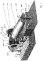
- Fig. 1 shows a rotor blade element 10, which is arranged on a rotor hub 12 with the interposition of a rotary joint 14.
- the rotary joint 14 is sometimes referred to as a pitch rotary joint.
- the rotor blade element 10 forms a rotor blade root, which is for example one fifth of the length of the entire rotor blade.
- a lifting device 16 has a foot 18, a hydraulic cylinder 20 and a force introduction device 22.
- the force introduction device 22 is in shape to the Contour of the rotor blade element 10 adapted and hingedly connected to the hydraulic cylinder 20.
- the rotor hub 12 is supported via a rotor hub adapter 24 on a foundation 26.
- a rotor hub adapter 24 on a foundation 26.
- Fig. 1 can be seen from the rotor hub adapter 24 two support elements 28a, 28b.
- Each of the support elements 28a, 28b has a connection flange 30 with which the support element is connected to the rotor hub 12.
- two lever arms 32a and 32b are provided on each of the support members 28a, 28b.
- the lever arms 32a, 32b do not rest on the foundation 26, but are connected via hydraulic stabilizing cylinders 34 to the end of the lever arms 32a, 32b.
- the rotor hub holder 24 additionally has a foot adapter (not shown), which is connected to a shaft flange of the rotor hub and rests on the foundation 26.
- a force is introduced into the rotor blade element via the lifting cylinder 20.
- To initiate the force of the lifting cylinder 20 is shortened, as well as the hydraulic cylinder 34 on the support element.
- a bending moment for the rotary joint 14 comes from the (Qkk device) 36 and is accepted.
- the transverse force compensation device 36 has a circumferential belt 38 and a deflection element 40 and a tensioning rocker 42. Between the elements 40, 42, one or more clamping cylinders 44 are provided. Clamping rocker 42 and deflecting element 40 each have a roller pair 46a, 46b, 48a, 48b. The endless belt 38 is guided over the roller pairs 46a, 46b, 48a, 48b. Between the deflecting element and the tensioning rocker, the tensioning cylinder 44 acts which, in the case of an extension, increases the distance between the rollers 46b and 48b in the direction of the double arrow A. The magnification is due to a pivoting movement the tensioning rocker 42 achieved in the direction of the double arrow B. For this purpose, the arm 49 of the tensioning rocker 42 is pivotally hinged below the roller 48 a.
- this has a travel drive 50 with which it can move in the rotor blade longitudinal direction, which is particularly advantageous for an exchange of the pitch turning connection and / or the rotor blade element.
- the ratio of lateral force and load moment on the pitch turning joint is set mainly by the pressure in the tensioning cylinder (s) and the lifter, the lateral force compensation is operated as close as possible to the pitch turning joint, so as to minimize the main load counteracting moment of the QKK device possible to keep.
- the rotor blade element preferably lies close to the rotary connection on the belt, which is held and tensioned by the transverse force compensation device.
- the voltage is in the test mode in synchronism with the initiation of the transverse force on the lifting device 16th
- Fig. 1 also shows in a schematic representation of the essential occurring on the test bench according to the invention forces F and moments M.
- the loading force F B is introduced via the lifting device 16.
- the supporting force F S is applied by the tensioned belt.
- the load moment M B arises, which acts on the pitch turning joint.
- the adapter torque M A is applied by the rotor hub holder, in particular by the rotor hub adapter which is supported on the foundation body.
- the counter-moments M G on the support elements are applied via the stabilization cylinder 34 with the stabilization force F S.
Landscapes
- Engineering & Computer Science (AREA)
- Aviation & Aerospace Engineering (AREA)
- Physics & Mathematics (AREA)
- General Physics & Mathematics (AREA)
- Investigating Strength Of Materials By Application Of Mechanical Stress (AREA)
Priority Applications (1)
| Application Number | Priority Date | Filing Date | Title |
|---|---|---|---|
| EP17175755.2A EP3415890B1 (fr) | 2017-06-13 | 2017-06-13 | Banc d'essai pour un raccord d'articulation de pas |
Applications Claiming Priority (1)
| Application Number | Priority Date | Filing Date | Title |
|---|---|---|---|
| EP17175755.2A EP3415890B1 (fr) | 2017-06-13 | 2017-06-13 | Banc d'essai pour un raccord d'articulation de pas |
Publications (2)
| Publication Number | Publication Date |
|---|---|
| EP3415890A1 true EP3415890A1 (fr) | 2018-12-19 |
| EP3415890B1 EP3415890B1 (fr) | 2020-06-03 |
Family
ID=59067527
Family Applications (1)
| Application Number | Title | Priority Date | Filing Date |
|---|---|---|---|
| EP17175755.2A Active EP3415890B1 (fr) | 2017-06-13 | 2017-06-13 | Banc d'essai pour un raccord d'articulation de pas |
Country Status (1)
| Country | Link |
|---|---|
| EP (1) | EP3415890B1 (fr) |
Cited By (2)
| Publication number | Priority date | Publication date | Assignee | Title |
|---|---|---|---|---|
| CN113173261A (zh) * | 2021-04-20 | 2021-07-27 | 中国直升机设计研究所 | 一种旋翼天平装试验台复合加载现场校核装置及方法 |
| CN114088390A (zh) * | 2021-11-15 | 2022-02-25 | 江苏科技大学 | 透平机械基础变加速度运动仿真测试平台及运动仿真方法 |
Citations (5)
| Publication number | Priority date | Publication date | Assignee | Title |
|---|---|---|---|---|
| DE202010003033U1 (de) * | 2010-02-17 | 2010-05-27 | Nordex Energy Gmbh | Hebezeug zur Positionierung eines Rotorblatts einer Windenergieanlage |
| EP2315940A2 (fr) | 2008-06-30 | 2011-05-04 | Vestas Wind Systems A/S | Banc d'essai pour tester les pales d'une éolienne |
| EP2650666A2 (fr) | 2012-04-10 | 2013-10-16 | Friedrich Prof. Dr.-Ing. Klinger | Dispositif de contrôle de charge sur des éoliennes |
| KR101482778B1 (ko) * | 2014-05-22 | 2015-01-19 | 한국기계연구원 | 블레이드 피로시험용 비틀림발생장치 및 이를 이용한 피로시험 방법 |
| EP2741068B1 (fr) | 2012-12-05 | 2016-11-02 | Industrieanlagen-Betriebsgesellschaft mbH | Banc d'essai pour une pale de rotor, dispositif doté d'un tel banc d'essai et procédé de fonctionnement d'un tel banc d'essai |
-
2017
- 2017-06-13 EP EP17175755.2A patent/EP3415890B1/fr active Active
Patent Citations (5)
| Publication number | Priority date | Publication date | Assignee | Title |
|---|---|---|---|---|
| EP2315940A2 (fr) | 2008-06-30 | 2011-05-04 | Vestas Wind Systems A/S | Banc d'essai pour tester les pales d'une éolienne |
| DE202010003033U1 (de) * | 2010-02-17 | 2010-05-27 | Nordex Energy Gmbh | Hebezeug zur Positionierung eines Rotorblatts einer Windenergieanlage |
| EP2650666A2 (fr) | 2012-04-10 | 2013-10-16 | Friedrich Prof. Dr.-Ing. Klinger | Dispositif de contrôle de charge sur des éoliennes |
| EP2741068B1 (fr) | 2012-12-05 | 2016-11-02 | Industrieanlagen-Betriebsgesellschaft mbH | Banc d'essai pour une pale de rotor, dispositif doté d'un tel banc d'essai et procédé de fonctionnement d'un tel banc d'essai |
| KR101482778B1 (ko) * | 2014-05-22 | 2015-01-19 | 한국기계연구원 | 블레이드 피로시험용 비틀림발생장치 및 이를 이용한 피로시험 방법 |
Cited By (2)
| Publication number | Priority date | Publication date | Assignee | Title |
|---|---|---|---|---|
| CN113173261A (zh) * | 2021-04-20 | 2021-07-27 | 中国直升机设计研究所 | 一种旋翼天平装试验台复合加载现场校核装置及方法 |
| CN114088390A (zh) * | 2021-11-15 | 2022-02-25 | 江苏科技大学 | 透平机械基础变加速度运动仿真测试平台及运动仿真方法 |
Also Published As
| Publication number | Publication date |
|---|---|
| EP3415890B1 (fr) | 2020-06-03 |
Similar Documents
| Publication | Publication Date | Title |
|---|---|---|
| EP3874248B1 (fr) | Procédé et dispositif d'essai pour soumettre à essai des pales de rotor | |
| DE102009002678B4 (de) | Prüfverfahren für Drehgestelle sowie Prüf- und Montagestand | |
| EP2741068B1 (fr) | Banc d'essai pour une pale de rotor, dispositif doté d'un tel banc d'essai et procédé de fonctionnement d'un tel banc d'essai | |
| DE2659633C3 (de) | Windkanalanlage | |
| DE112013003362T5 (de) | Düsenberührungsmechanismus und Spritzgießmaschine | |
| EP2330399A1 (fr) | Système de contrôle de la rigidité de fonctionnement d'une éprouvette, en particulier d'un train de roues pour véhicules ferroviaires | |
| EP3415890A1 (fr) | Banc d'essai pour un raccord d'articulation de pas | |
| EP3704460B1 (fr) | Dispositif de test de structure | |
| DE102010017455B4 (de) | Vorrichtung und Verfahren zur Prüfung der Betriebsfestigkeit eines Körpers | |
| DE10135594A1 (de) | Hebebühne für Fahrzeuge | |
| DE3204472C2 (de) | Umlaufbiegemaschine | |
| DE19945189B4 (de) | Hebezeug | |
| EP3105164B2 (fr) | Socle de grue pour une grue de chargement | |
| DE69217537T2 (de) | Penetrometerkopf mit Gehäuse, und seine Anwendung | |
| DE102008034403A1 (de) | Messanordnung zum Messen der linearen Kraftverteilung eines Wischblatts gegen eine Scheibe | |
| DE10205669C5 (de) | Hubladebühnenvorrichtung für Fahrzeuge | |
| WO2009153026A1 (fr) | Portique rotatif pour un four | |
| DE102007015438A1 (de) | Verstellanordnung mit einem Scherengestell, insbesondere Federelement | |
| DE102023208694A1 (de) | Prüfvorrichtung und Prüfverfahren zum Prüfen eines Drehlagers | |
| DE102015006778A1 (de) | System und Verfahren zum Transportieren und Heben eines Rotorblatts einer Windenergieanlage | |
| EP4229384B1 (fr) | Dispositif et procédé de serrage d'une éprouvette | |
| EP2946991B1 (fr) | Dispositif de levage pour un essieu d'un véhicule | |
| DE102022112753B4 (de) | Vorrichtung zum Beeinflussen eines Faltvorgangs einer faltbaren Plattform, faltbare Plattform welche die Vorrichtung umfasst | |
| DE102017004057A1 (de) | Prüfvorrichtung, Verfahren zur Prüfung eines Prüflings und Verwendung der Prüfvorrichtung | |
| DE102005039945B4 (de) | Scherenhubtisch |
Legal Events
| Date | Code | Title | Description |
|---|---|---|---|
| PUAI | Public reference made under article 153(3) epc to a published international application that has entered the european phase |
Free format text: ORIGINAL CODE: 0009012 |
|
| STAA | Information on the status of an ep patent application or granted ep patent |
Free format text: STATUS: THE APPLICATION HAS BEEN PUBLISHED |
|
| AK | Designated contracting states |
Kind code of ref document: A1 Designated state(s): AL AT BE BG CH CY CZ DE DK EE ES FI FR GB GR HR HU IE IS IT LI LT LU LV MC MK MT NL NO PL PT RO RS SE SI SK SM TR |
|
| AX | Request for extension of the european patent |
Extension state: BA ME |
|
| STAA | Information on the status of an ep patent application or granted ep patent |
Free format text: STATUS: REQUEST FOR EXAMINATION WAS MADE |
|
| 17P | Request for examination filed |
Effective date: 20190415 |
|
| RBV | Designated contracting states (corrected) |
Designated state(s): AL AT BE BG CH CY CZ DE DK EE ES FI FR GB GR HR HU IE IS IT LI LT LU LV MC MK MT NL NO PL PT RO RS SE SI SK SM TR |
|
| GRAP | Despatch of communication of intention to grant a patent |
Free format text: ORIGINAL CODE: EPIDOSNIGR1 |
|
| STAA | Information on the status of an ep patent application or granted ep patent |
Free format text: STATUS: GRANT OF PATENT IS INTENDED |
|
| INTG | Intention to grant announced |
Effective date: 20200117 |
|
| GRAS | Grant fee paid |
Free format text: ORIGINAL CODE: EPIDOSNIGR3 |
|
| GRAA | (expected) grant |
Free format text: ORIGINAL CODE: 0009210 |
|
| STAA | Information on the status of an ep patent application or granted ep patent |
Free format text: STATUS: THE PATENT HAS BEEN GRANTED |
|
| AK | Designated contracting states |
Kind code of ref document: B1 Designated state(s): AL AT BE BG CH CY CZ DE DK EE ES FI FR GB GR HR HU IE IS IT LI LT LU LV MC MK MT NL NO PL PT RO RS SE SI SK SM TR |
|
| REG | Reference to a national code |
Ref country code: GB Ref legal event code: FG4D Free format text: NOT ENGLISH |
|
| REG | Reference to a national code |
Ref country code: CH Ref legal event code: EP Ref country code: AT Ref legal event code: REF Ref document number: 1277504 Country of ref document: AT Kind code of ref document: T Effective date: 20200615 |
|
| REG | Reference to a national code |
Ref country code: DE Ref legal event code: R096 Ref document number: 502017005514 Country of ref document: DE |
|
| REG | Reference to a national code |
Ref country code: LT Ref legal event code: MG4D |
|
| PG25 | Lapsed in a contracting state [announced via postgrant information from national office to epo] |
Ref country code: GR Free format text: LAPSE BECAUSE OF FAILURE TO SUBMIT A TRANSLATION OF THE DESCRIPTION OR TO PAY THE FEE WITHIN THE PRESCRIBED TIME-LIMIT Effective date: 20200904 Ref country code: NO Free format text: LAPSE BECAUSE OF FAILURE TO SUBMIT A TRANSLATION OF THE DESCRIPTION OR TO PAY THE FEE WITHIN THE PRESCRIBED TIME-LIMIT Effective date: 20200903 Ref country code: FI Free format text: LAPSE BECAUSE OF FAILURE TO SUBMIT A TRANSLATION OF THE DESCRIPTION OR TO PAY THE FEE WITHIN THE PRESCRIBED TIME-LIMIT Effective date: 20200603 Ref country code: SE Free format text: LAPSE BECAUSE OF FAILURE TO SUBMIT A TRANSLATION OF THE DESCRIPTION OR TO PAY THE FEE WITHIN THE PRESCRIBED TIME-LIMIT Effective date: 20200603 Ref country code: LT Free format text: LAPSE BECAUSE OF FAILURE TO SUBMIT A TRANSLATION OF THE DESCRIPTION OR TO PAY THE FEE WITHIN THE PRESCRIBED TIME-LIMIT Effective date: 20200603 |
|
| REG | Reference to a national code |
Ref country code: NL Ref legal event code: MP Effective date: 20200603 |
|
| PG25 | Lapsed in a contracting state [announced via postgrant information from national office to epo] |
Ref country code: BG Free format text: LAPSE BECAUSE OF FAILURE TO SUBMIT A TRANSLATION OF THE DESCRIPTION OR TO PAY THE FEE WITHIN THE PRESCRIBED TIME-LIMIT Effective date: 20200903 Ref country code: HR Free format text: LAPSE BECAUSE OF FAILURE TO SUBMIT A TRANSLATION OF THE DESCRIPTION OR TO PAY THE FEE WITHIN THE PRESCRIBED TIME-LIMIT Effective date: 20200603 Ref country code: LV Free format text: LAPSE BECAUSE OF FAILURE TO SUBMIT A TRANSLATION OF THE DESCRIPTION OR TO PAY THE FEE WITHIN THE PRESCRIBED TIME-LIMIT Effective date: 20200603 Ref country code: RS Free format text: LAPSE BECAUSE OF FAILURE TO SUBMIT A TRANSLATION OF THE DESCRIPTION OR TO PAY THE FEE WITHIN THE PRESCRIBED TIME-LIMIT Effective date: 20200603 |
|
| PG25 | Lapsed in a contracting state [announced via postgrant information from national office to epo] |
Ref country code: NL Free format text: LAPSE BECAUSE OF FAILURE TO SUBMIT A TRANSLATION OF THE DESCRIPTION OR TO PAY THE FEE WITHIN THE PRESCRIBED TIME-LIMIT Effective date: 20200603 Ref country code: AL Free format text: LAPSE BECAUSE OF FAILURE TO SUBMIT A TRANSLATION OF THE DESCRIPTION OR TO PAY THE FEE WITHIN THE PRESCRIBED TIME-LIMIT Effective date: 20200603 |
|
| REG | Reference to a national code |
Ref country code: DE Ref legal event code: R119 Ref document number: 502017005514 Country of ref document: DE |
|
| PG25 | Lapsed in a contracting state [announced via postgrant information from national office to epo] |
Ref country code: EE Free format text: LAPSE BECAUSE OF FAILURE TO SUBMIT A TRANSLATION OF THE DESCRIPTION OR TO PAY THE FEE WITHIN THE PRESCRIBED TIME-LIMIT Effective date: 20200603 Ref country code: SM Free format text: LAPSE BECAUSE OF FAILURE TO SUBMIT A TRANSLATION OF THE DESCRIPTION OR TO PAY THE FEE WITHIN THE PRESCRIBED TIME-LIMIT Effective date: 20200603 Ref country code: PT Free format text: LAPSE BECAUSE OF FAILURE TO SUBMIT A TRANSLATION OF THE DESCRIPTION OR TO PAY THE FEE WITHIN THE PRESCRIBED TIME-LIMIT Effective date: 20201006 Ref country code: CZ Free format text: LAPSE BECAUSE OF FAILURE TO SUBMIT A TRANSLATION OF THE DESCRIPTION OR TO PAY THE FEE WITHIN THE PRESCRIBED TIME-LIMIT Effective date: 20200603 Ref country code: IT Free format text: LAPSE BECAUSE OF FAILURE TO SUBMIT A TRANSLATION OF THE DESCRIPTION OR TO PAY THE FEE WITHIN THE PRESCRIBED TIME-LIMIT Effective date: 20200603 Ref country code: ES Free format text: LAPSE BECAUSE OF FAILURE TO SUBMIT A TRANSLATION OF THE DESCRIPTION OR TO PAY THE FEE WITHIN THE PRESCRIBED TIME-LIMIT Effective date: 20200603 Ref country code: RO Free format text: LAPSE BECAUSE OF FAILURE TO SUBMIT A TRANSLATION OF THE DESCRIPTION OR TO PAY THE FEE WITHIN THE PRESCRIBED TIME-LIMIT Effective date: 20200603 |
|
| REG | Reference to a national code |
Ref country code: CH Ref legal event code: PL |
|
| PG25 | Lapsed in a contracting state [announced via postgrant information from national office to epo] |
Ref country code: PL Free format text: LAPSE BECAUSE OF FAILURE TO SUBMIT A TRANSLATION OF THE DESCRIPTION OR TO PAY THE FEE WITHIN THE PRESCRIBED TIME-LIMIT Effective date: 20200603 Ref country code: SK Free format text: LAPSE BECAUSE OF FAILURE TO SUBMIT A TRANSLATION OF THE DESCRIPTION OR TO PAY THE FEE WITHIN THE PRESCRIBED TIME-LIMIT Effective date: 20200603 Ref country code: IS Free format text: LAPSE BECAUSE OF FAILURE TO SUBMIT A TRANSLATION OF THE DESCRIPTION OR TO PAY THE FEE WITHIN THE PRESCRIBED TIME-LIMIT Effective date: 20201003 |
|
| PG25 | Lapsed in a contracting state [announced via postgrant information from national office to epo] |
Ref country code: LU Free format text: LAPSE BECAUSE OF NON-PAYMENT OF DUE FEES Effective date: 20200613 Ref country code: MC Free format text: LAPSE BECAUSE OF FAILURE TO SUBMIT A TRANSLATION OF THE DESCRIPTION OR TO PAY THE FEE WITHIN THE PRESCRIBED TIME-LIMIT Effective date: 20200603 |
|
| PLBE | No opposition filed within time limit |
Free format text: ORIGINAL CODE: 0009261 |
|
| STAA | Information on the status of an ep patent application or granted ep patent |
Free format text: STATUS: NO OPPOSITION FILED WITHIN TIME LIMIT |
|
| REG | Reference to a national code |
Ref country code: BE Ref legal event code: MM Effective date: 20200630 |
|
| PG25 | Lapsed in a contracting state [announced via postgrant information from national office to epo] |
Ref country code: CH Free format text: LAPSE BECAUSE OF NON-PAYMENT OF DUE FEES Effective date: 20200630 Ref country code: DK Free format text: LAPSE BECAUSE OF FAILURE TO SUBMIT A TRANSLATION OF THE DESCRIPTION OR TO PAY THE FEE WITHIN THE PRESCRIBED TIME-LIMIT Effective date: 20200603 Ref country code: LI Free format text: LAPSE BECAUSE OF NON-PAYMENT OF DUE FEES Effective date: 20200630 Ref country code: IE Free format text: LAPSE BECAUSE OF NON-PAYMENT OF DUE FEES Effective date: 20200613 Ref country code: FR Free format text: LAPSE BECAUSE OF NON-PAYMENT OF DUE FEES Effective date: 20200803 |
|
| 26N | No opposition filed |
Effective date: 20210304 |
|
| PG25 | Lapsed in a contracting state [announced via postgrant information from national office to epo] |
Ref country code: DE Free format text: LAPSE BECAUSE OF NON-PAYMENT OF DUE FEES Effective date: 20210101 Ref country code: BE Free format text: LAPSE BECAUSE OF NON-PAYMENT OF DUE FEES Effective date: 20200630 Ref country code: SI Free format text: LAPSE BECAUSE OF FAILURE TO SUBMIT A TRANSLATION OF THE DESCRIPTION OR TO PAY THE FEE WITHIN THE PRESCRIBED TIME-LIMIT Effective date: 20200603 |
|
| GBPC | Gb: european patent ceased through non-payment of renewal fee |
Effective date: 20210613 |
|
| PG25 | Lapsed in a contracting state [announced via postgrant information from national office to epo] |
Ref country code: GB Free format text: LAPSE BECAUSE OF NON-PAYMENT OF DUE FEES Effective date: 20210613 |
|
| PG25 | Lapsed in a contracting state [announced via postgrant information from national office to epo] |
Ref country code: TR Free format text: LAPSE BECAUSE OF FAILURE TO SUBMIT A TRANSLATION OF THE DESCRIPTION OR TO PAY THE FEE WITHIN THE PRESCRIBED TIME-LIMIT Effective date: 20200603 Ref country code: MT Free format text: LAPSE BECAUSE OF FAILURE TO SUBMIT A TRANSLATION OF THE DESCRIPTION OR TO PAY THE FEE WITHIN THE PRESCRIBED TIME-LIMIT Effective date: 20200603 Ref country code: CY Free format text: LAPSE BECAUSE OF FAILURE TO SUBMIT A TRANSLATION OF THE DESCRIPTION OR TO PAY THE FEE WITHIN THE PRESCRIBED TIME-LIMIT Effective date: 20200603 |
|
| PG25 | Lapsed in a contracting state [announced via postgrant information from national office to epo] |
Ref country code: MK Free format text: LAPSE BECAUSE OF FAILURE TO SUBMIT A TRANSLATION OF THE DESCRIPTION OR TO PAY THE FEE WITHIN THE PRESCRIBED TIME-LIMIT Effective date: 20200603 |
|
| REG | Reference to a national code |
Ref country code: AT Ref legal event code: MM01 Ref document number: 1277504 Country of ref document: AT Kind code of ref document: T Effective date: 20220613 |
|
| PG25 | Lapsed in a contracting state [announced via postgrant information from national office to epo] |
Ref country code: AT Free format text: LAPSE BECAUSE OF NON-PAYMENT OF DUE FEES Effective date: 20220613 |