EP3425471B1 - Verfahren zum störungsfreien transport von lastregalen in werkshallen mit teilweise autonomem fahrbetrieb - Google Patents
Verfahren zum störungsfreien transport von lastregalen in werkshallen mit teilweise autonomem fahrbetrieb Download PDFInfo
- Publication number
- EP3425471B1 EP3425471B1 EP18191141.3A EP18191141A EP3425471B1 EP 3425471 B1 EP3425471 B1 EP 3425471B1 EP 18191141 A EP18191141 A EP 18191141A EP 3425471 B1 EP3425471 B1 EP 3425471B1
- Authority
- EP
- European Patent Office
- Prior art keywords
- transport vehicle
- load
- load shelf
- shelf
- route
- Prior art date
- Legal status (The legal status is an assumption and is not a legal conclusion. Google has not performed a legal analysis and makes no representation as to the accuracy of the status listed.)
- Active
Links
Images


Classifications
-
- G—PHYSICS
- G05—CONTROLLING; REGULATING
- G05D—SYSTEMS FOR CONTROLLING OR REGULATING NON-ELECTRIC VARIABLES
- G05D1/00—Control of position, course, altitude or attitude of land, water, air or space vehicles, e.g. using automatic pilots
- G05D1/02—Control of position or course in two dimensions
- G05D1/021—Control of position or course in two dimensions specially adapted to land vehicles
- G05D1/0287—Control of position or course in two dimensions specially adapted to land vehicles involving a plurality of land vehicles, e.g. fleet or convoy travelling
- G05D1/0291—Fleet control
- G05D1/0297—Fleet control by controlling means in a control room
-
- B—PERFORMING OPERATIONS; TRANSPORTING
- B60—VEHICLES IN GENERAL
- B60P—VEHICLES ADAPTED FOR LOAD TRANSPORTATION OR TO TRANSPORT, TO CARRY, OR TO COMPRISE SPECIAL LOADS OR OBJECTS
- B60P1/00—Vehicles predominantly for transporting loads and modified to facilitate loading, consolidating the load, or unloading
- B60P1/02—Vehicles predominantly for transporting loads and modified to facilitate loading, consolidating the load, or unloading with parallel up-and-down movement of load supporting or containing element
-
- B—PERFORMING OPERATIONS; TRANSPORTING
- B60—VEHICLES IN GENERAL
- B60P—VEHICLES ADAPTED FOR LOAD TRANSPORTATION OR TO TRANSPORT, TO CARRY, OR TO COMPRISE SPECIAL LOADS OR OBJECTS
- B60P1/00—Vehicles predominantly for transporting loads and modified to facilitate loading, consolidating the load, or unloading
- B60P1/64—Vehicles predominantly for transporting loads and modified to facilitate loading, consolidating the load, or unloading the load supporting or containing element being readily removable
- B60P1/6409—Vehicles predominantly for transporting loads and modified to facilitate loading, consolidating the load, or unloading the load supporting or containing element being readily removable details, accessories, auxiliary devices
-
- B—PERFORMING OPERATIONS; TRANSPORTING
- B66—HOISTING; LIFTING; HAULING
- B66F—HOISTING, LIFTING, HAULING OR PUSHING, NOT OTHERWISE PROVIDED FOR, e.g. DEVICES WHICH APPLY A LIFTING OR PUSHING FORCE DIRECTLY TO THE SURFACE OF A LOAD
- B66F9/00—Devices for lifting or lowering bulky or heavy goods for loading or unloading purposes
- B66F9/06—Devices for lifting or lowering bulky or heavy goods for loading or unloading purposes movable, with their loads, on wheels or the like, e.g. fork-lift trucks
- B66F9/063—Automatically guided
-
- B—PERFORMING OPERATIONS; TRANSPORTING
- B66—HOISTING; LIFTING; HAULING
- B66F—HOISTING, LIFTING, HAULING OR PUSHING, NOT OTHERWISE PROVIDED FOR, e.g. DEVICES WHICH APPLY A LIFTING OR PUSHING FORCE DIRECTLY TO THE SURFACE OF A LOAD
- B66F9/00—Devices for lifting or lowering bulky or heavy goods for loading or unloading purposes
- B66F9/06—Devices for lifting or lowering bulky or heavy goods for loading or unloading purposes movable, with their loads, on wheels or the like, e.g. fork-lift trucks
- B66F9/075—Constructional features or details
- B66F9/0755—Position control; Position detectors
-
- B—PERFORMING OPERATIONS; TRANSPORTING
- B66—HOISTING; LIFTING; HAULING
- B66F—HOISTING, LIFTING, HAULING OR PUSHING, NOT OTHERWISE PROVIDED FOR, e.g. DEVICES WHICH APPLY A LIFTING OR PUSHING FORCE DIRECTLY TO THE SURFACE OF A LOAD
- B66F9/00—Devices for lifting or lowering bulky or heavy goods for loading or unloading purposes
- B66F9/06—Devices for lifting or lowering bulky or heavy goods for loading or unloading purposes movable, with their loads, on wheels or the like, e.g. fork-lift trucks
- B66F9/075—Constructional features or details
- B66F9/07586—Suspension or mounting of wheels on chassis
-
- G—PHYSICS
- G05—CONTROLLING; REGULATING
- G05D—SYSTEMS FOR CONTROLLING OR REGULATING NON-ELECTRIC VARIABLES
- G05D1/00—Control of position, course, altitude or attitude of land, water, air or space vehicles, e.g. using automatic pilots
- G05D1/02—Control of position or course in two dimensions
- G05D1/021—Control of position or course in two dimensions specially adapted to land vehicles
- G05D1/0231—Control of position or course in two dimensions specially adapted to land vehicles using optical position detecting means
- G05D1/0238—Control of position or course in two dimensions specially adapted to land vehicles using optical position detecting means using obstacle or wall sensors
- G05D1/024—Control of position or course in two dimensions specially adapted to land vehicles using optical position detecting means using obstacle or wall sensors in combination with a laser
Definitions
- the present invention relates to a method for the trouble-free transport of load racks in factory halls with partially autonomous driving operation.
- a container can be a packaged or unpacked piece of goods or a combination of goods such as a box, a carton or a crate with bulk goods or several individual goods such as drinks bottles or dairy products.
- AGVs automated guided vehicles
- AGVs automated guided vehicles
- Conventional automated guided vehicles which are used to move materials in factories and warehouses, for example, have minimal point-to-point motion control.
- Most such systems use AGVs that follow a fixed guide track. This is generally a high-frequency transmitting antenna wire that is recessed into the factory floor, a reflective strip painted on the floor, or a reflective tape.
- guide tracks are obviously very vulnerable and unreliable.
- All of these motion controls limit the freedom of movement of individual AGVs by forcing them to follow a physically defined path.
- the control scheme implements a "static" collision avoidance scheme for AGV systems. Essentially, a computer program is used to examine the environment of an AGV to determine only those paths that are passable for AGVs. Another allocation program uses this to extract the necessary data to move AGVs from one point to another point in the system without two AGVs traveling the same path at the same time.
- the DE 689 28 565 T2 According to the information in claim 1, a method for guiding several automatically guided vehicles (AGV) along a network of interconnected paths that begin, end, and contain nodes.
- AGV automatically guided vehicles
- This method involves creating a record of a route to be followed by the specific AGV in the form of path segments starting at a node and ending at the next node.
- An indication of the position of a specific AGV is also determined.
- each node an indication is derived as to whether it is free or occupied.
- a list of nodes is generated that includes the node currently visited by the particular AGV, at least some nodes along the recorded route that the particular AGV will visit. This includes checking that each node in the list is free before adding it to the list, and marking each node in the list as busy after adding it to the list. Further, the list of nodes is transmitted to the particular AGV and causing it to move forward along the recorded route through the nodes.
- the publication US 2008/001372 A1 discloses a method for operating a transport vehicle for the trouble-free transport of load racks in factory halls with partially autonomous driving, wherein a control center ensures that a load rack with a transport item located on it is transported to a destination, wherein the control center determines which transport vehicle is able to complete the required order most quickly due to its current location and its current order situation, and the transport vehicle then receives an order from the control center to search for the load rack in a larger area of a storage area, to pick up the load rack and to transport the load rack with the goods on it to the destination.
- the transport vehicle selected by the control center receives route instructions regarding the route to be taken and the speed to be driven in each section of the route in order to reach the destination within a certain time frame.
- the transport vehicle uses a sensor to detect the load rack to be picked up, selects a suitable starting position for picking up the load rack, drives underneath it and lifts it up for removal.
- the invention is therefore based on the object of creating a method for operating a transport vehicle with which the reliable transport of load racks can be carried out without disruption even on uneven ground and on slight inclines.
- the Fig.1 shows an arrangement of load racks to be transported.
- the Fig.2 shows an approach of a transport vehicle 9 to load racks 1.
- FIG.2 In the left area of the Fig.2 Two load racks 1 standing one behind the other with their shelf posts 7 and the goods to be transported 2 are shown.
- a transport vehicle 9 approaches these two load racks 1 by means of two drive wheels 5, of which only one can be seen in the side view, and a front and a rear support wheel 8.
- the transport vehicle 9 has a support plate 4 that is adjustable in height.
- each of these Vehicles have at least one laser scanner 3 and one light field sensor 6 on the front.
- mini lenses which collect optical information in the form of hundreds of mini lenses based on the light field principle, which can then later be compiled into images with a desired resolution and/or a desired viewing angle.
- mini lenses are 3D capable, inexpensive to manufacture and follow the principle of an insect eye.
- Fig.3 shows a representation of shelf posts as an orientation aid.
- Each shelf post 7 can have a marking in the form of a barcode or data matrix code on each of its four sides, which identifies it as part of a specific storage shelf and makes it identifiable from all sides for a transport vehicle 9, primarily by means of its laser scanner.
- the Fig.4 shows an orientation situation of a transport vehicle 9 with real obstacles.
- this involves a normal load rack 1, which can be identified as previously described, and on the other hand, a person 10 who does not actually belong in this environment.
- a person 10 who represents an unusual obstacle is detected by a transport vehicle 9 using a light field sensor.
- the Fig.5 shows a side view of a loaded transport vehicle 9. Its drive wheels and the support wheels touch the floor and the load shelf 1 rests on the carrier plate of the transport vehicle
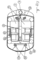
- the Fig.6 shows a top view of the kinematics of the transport vehicle 9.
- an adjusting element 17 In a central position in the longitudinal direction, an adjusting element 17 can be seen which, when extended in the longitudinal direction, causes the four circular centering elements 14 shown to be raised via lifting elements that are not visible in this illustration.
- the centering elements 14 fit into corresponding recesses in the carrier plate.
- the rear support plate suspension 12 and the front support plate suspension 15 can be seen as part of the lever elements mentioned.
- the adjusting element 17 rests on a wishbone 13 which is connected to the two rear lifting rod levers 11 via lifting elements that are not visible here.
- both servomotors for the two drive wheels can be seen, although only the left one is marked 18.
- the spring elements leading to both drive wheels ensure that the drive wheels maintain secure contact with the ground even on uneven ground via deflection levers (not visible here).
- only the spring element on the left in the direction of travel is marked 19.
- 16 represents a left-hand and a right-hand space for energy storage. These can be electric batteries or energy storage for other liquid or gaseous forms of energy.
- a laser scanner 3 and a light field sensor 6 are mounted on the front of the transport vehicle 9.
- both types of sensors can also be additionally mounted on the two sides and/or on the rear of a transport vehicle.
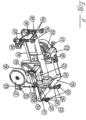
- the Fig.7 shows a detailed representation of the kinematics of the transport vehicle.
- This illustration shows the transport vehicle without the enclosing housing. Connections to the Housing is indicated at the appropriate point.
- the kinematics of the drive wheels are explained.
- In the foreground is the Fig. 2 known, left-hand drive wheel 5 and the associated rotation axis 32 can be seen, which is attached to the unspecified housing of the transport vehicle.
- the axle bearing 34 for the left-hand drive wheel 5 with its servo motor 18 above it, which serves as a drive for the drive wheel 5, are connected to form a functional unit by means of an angle plate, unspecified and only visible from the rear.
- a toothed belt runs in this angle plate, over which the servo motor 18 drives the rotation axis of the left-hand drive wheel 5.
- the corresponding servo motor 22 for the right-hand drive can be seen.
- the corresponding angle plate can be seen from the rear in the illustration shown.
- the corresponding toothed belt 20 running in this angle plate is marked.
- the entire functional unit, consisting of the drive wheel 5 with the axle bearing 34, the servo motor 18 and the angle plate with its toothed belt, can be pivoted about the above-mentioned axis of rotation 32 via an angle lever 31.
- the angle lever 31 is connected via a joint 30 to a U-shaped wishbone 13 that runs across almost the entire width of the transport vehicle, to the other end of which the right-hand drive wheel is attached accordingly.
- a spring element 19 is also mounted on the joint 30, the other bearing point of which is attached to the housing of the transport vehicle.
- this articulation point is shown as a block-shaped, barely recognizable bearing above the drive wheel 5.
- this point is designated as the articulation point 21 of the corresponding right spring element.
- the spring element 19 serves the purpose of pressing the drive wheel 5 onto the ground surface via the angle lever 31 and thus improving the ground contact of the drive wheel 5. The same applies to the opposite right drive wheel.
- the front lifting rods 40 and the rear lifting rods 26 serve this purpose in direct contact.
- the lifting rods 40 and 26 are raised and lowered by means of an actuating element 17, which in turn applies the necessary forces by means of a threaded spindle via a retractable and extendable cylinder via a joint head 39 and a hinged lifting rotary lever 38.
- the front lifting rods 40 each carry the corresponding front carrier plate suspension.
- a push rod 35 is articulated on the lifting-rotary lever 38, which transmits the movements of the lifting-rotary lever 38 via an axle lever 29 to a rear push rod lever 11.
- the movements of the rear push rod levers 11 lead to the necessary raising or lowering of the two rear lifting rods 26.
- the rear lifting rods 26 each carry the corresponding rear support plate suspension 25, a corresponding connecting element with the housing is designated with 28.
- the front support plate suspension is designated with 15.
- the movement of the actuating element 17, or its threaded spindle, takes place via a drive 23 and a force transmission 24 that redirects the force.
- the force transmission 24 is attached to the wishbone 13 by means of a fork head 33. Since the fork head 33 is rotatably mounted on the wishbone 13, the wishbone 13 can move as a connecting element between the angle levers 31 and its opposite counterpart, thus enabling the two drive wheels to carry out vertical pivoting movements independent of one another.
- the front lifting rods 40 and the rear lifting rods 26 each have additional adjusting elements which lift the entire carrier plate out of a locking position which serves to secure the position during driving before the actual process of lifting the transported goods begins.
- the adjusting elements 27 are shown here as an example for the rear lifting rods. The control of the adjusting elements mentioned can be carried out separately and independently of the lifting of the transported goods described above.
- a special sensor is used to detect the inclination of the transport vehicle and the transported goods, but this is not specifically labelled.
- the center of gravity of the load rack 1 is detected by means of sensors, and the result of such a center of gravity determination is used to control the actuating elements of the lifting rods 40 and 26.
- sensors are provided for detecting the rotational movement of the drive wheels 5, which can also determine the slip on each drive wheel 5 depending on the speed of the transport vehicle.
- the inclination of a load shelf 1 is determined by means of an inclination sensor.
- the application of the method described here concerned an AGV network in the Altenwerder container terminal in the port of Hamburg.
- the application of the same method for the trouble-free operation of automated guided vehicles in a warehouse appears to be new.
- the control of the complex movement processes and the signal processing of the sensors used require a special control program.
Landscapes
- Engineering & Computer Science (AREA)
- Transportation (AREA)
- Structural Engineering (AREA)
- Mechanical Engineering (AREA)
- Physics & Mathematics (AREA)
- Civil Engineering (AREA)
- Life Sciences & Earth Sciences (AREA)
- Geology (AREA)
- Radar, Positioning & Navigation (AREA)
- Remote Sensing (AREA)
- Aviation & Aerospace Engineering (AREA)
- General Physics & Mathematics (AREA)
- Automation & Control Theory (AREA)
- Optics & Photonics (AREA)
- Electromagnetism (AREA)
- Warehouses Or Storage Devices (AREA)
- Vehicle Body Suspensions (AREA)
Description
- Die vorliegende Erfindung betrifft ein Verfahren zum störungsfreien Transport von Lastregalen in Werkshallen mit teilweise autonomem Fahrbetrieb.
- In einer Vielzahl von Unternehmensbereichen, zum Beispiel dem Handel mit Lebensmitteln und Haushaltsartikeln oder Industrie- und Haushaltsprodukten, liegen Waren in sortenreinen Quellpaletten mit gleichartigen Gebinden in Lastregalen vor. Ein Gebinde kann hierbei ein verpacktes oder unverpacktes Stückgut oder eine Warenzusammenstellung wie beispielsweise eine Kiste, ein Karton oder eine Steige mit Schüttgut oder mehreren Einzelgütern wie Getränkeflaschen oder Molkereiprodukten sein.
- Zur Zusammenstellung einer Lieferung an einen bestimmten Kunden müssen hieraus Pakete mit unterschiedlicher Bestückung oder Gebinden zusammengestellt werden.
- Das Herbeischaffen einzelner Bestandteile einer solchen Lieferung kann hierbei händisch erfolgen oder mittels automatisch geführter Fahrzeuge. Solche so genannten AGVs (automatic guided vehicles) können mobile Roboter oder speziell für den jeweiligen Verwendungszweck konstruierte Fahrzeuge sein, die mit einem speziellen Führungs- und Steuerungsverfahren von einem Ort zu einem anderen Ort bewegt werden. Herkömmliche automatisch geführte Fahrzeuge, mit denen zum Beispiel Materialien in Fabriken und Lagerhäusern bewegt werden, weisen eine minimale Punkt-zu-Punkt-Bewegungssteuerung auf. Die meisten solcher Systeme verwenden AGVs, die einer festen Leitspur folgen. Im Allgemeinen handelt es sich hierbei um einen Hochfrequenz-Sendeantennendraht, der im Fabrikboden versenkt angeordnet ist, einen auf den Boden aufgemalten reflektierenden Streifen, oder ein auf den Boden aufgeklebtes reflektierendes Band. Solche Leitspuren sind jedoch ersichtlich sehr verletzlich und unzuverlässig.
- Alle diese Bewegungssteuerungen begrenzen die Bewegungsfreiheit der einzelnen AGV's, indem diese gezwungen werden einem physikalisch festgelegten Weg zu folgen.
- Die meisten solcher Systeme verlassen sich auf die fahrzeugeigene Annäherungs-Detektion, um Kollisionen mit anderen Fahrzeugen, unbewegten Objekten oder menschlichem Personal zu vermeiden. In solchen Systemen können sich die AGV's nur in einer Richtung längs der von ihnen verfolgten Spur bewegen. Solche Systeme erreichen eine Punkt-zu-Punkt-Bewegung durch Implementieren von Steuerschemata und Verwenden frei beweglicher AGV's mit programmierbaren bidirektionalen Wegen. Hierdurch wird erreicht, dass sich mehrere AGV's ohne Kollisionen oder übermäßige Staus gleichzeitig auf denselben Wegen befinden.
- Diese Verfahren maximieren den Freiheitsgrad der AGV-Bewegung. Das Steuerschema implementiert hierbei ein Schema der "statischen" Kollisionsvermeidung für AGV-Systeme. Im Wesentlichen wird dabei ein Computerprogramm verwendet zum Untersuchen der jeweiligen Umgebung eines AGV's, um nur solche Wege zu ermitteln, die für AGV's befahrbar sind. Ein weiteres Zuteilungsprogramm zieht hieraus die erforderlichen Daten um AGV's im jeweiligen System von einem Punkt zu einem anderen Punkt zu bewegen, ohne dass zwei AGV's gleichzeitig denselben Weg befahren.
- Die Nachteile dieser Verfahren aus dem Stand der Technik bestehen darin, dass sie entweder auf geschlossene Pfade, eine unidirektionale Bewegung, auf das Fehlen der externen Steuerung der AGV-Bewegung oder auf die "statische" Kollisionsvermeidung beschränkt sind.
- Zur Vermeidung dieser Nachteile ist aus der
DE 689 28 565 T2 nach den Angaben im Patentanspruch 1 ein Verfahren zum Leiten von mehreren automatisch gelenkten Fahrzeugen (AGV) längs eines Netzes miteinander verbundener Wege bekannt, die bei Knotenpunkten beginnen, enden und Knotenpunkte enthalten. - Bei diesem Verfahren wird eine Aufzeichnung einer von den bestimmten AGV zu verfolgenden Route in Form von, bei einem Knotenpunkt beginnenden und beim nächsten Knotenpunkt endenden, Wegabschnitten erstellt.
- Es wird ferner eine Angabe der Position eines bestimmten AGV's festgestellt.
- Weiter wird für jeden Knotenpunkt eine Angabe abgeleitet, ob er frei oder besetzt ist.
- Ferner wird für ein bestimmtes AGV eine Liste von Knotenpunkten erzeugt, die den von dem bestimmten AGV gerade aufgesuchten Knotenpunkt um wenigstens einige Knotenpunkte längs der aufgezeichneten Route enthält, die das bestimmte AGV aufsuchen wird. Dies erfolgt einschließlich der Prüfung, dass jeder Knotenpunkt in der Liste frei ist, bevor er in die Liste aufgenommen wird, sowie der Markierung jedes Knotenpunkts in der Liste als besetzt, nachdem er in die Liste aufgenommen ist. Weiter erfolgt eine Übertragung der Liste von Knotenpunkten zu den bestimmten AGV's und das Veranlassen, dass es sich längs der aufgezeichneten Route durch die Knotenpunkte vorwärts bewegt.
- Die Druckschrift
US 2008/001372 A1 , auf der der Oberbegriff des Patentanspruchs 1 basiert, offenbart ein Verfahren zum Betrieb eines Transportfahrzeugs zum störungsfreien Transport von Lastregalen in Werkshallen mit teilweise autonomem Fahrbetrieb bekannt, wobei eine Leitzentrale dafür sorgt, dass ein Lastregal mit einem darauf befindlichen Transportgut zu einem Zielort transportiert wird, wobei die Leitzentrale ermittelt, welches Transportfahrzeug aufgrund seines derzeitigen Standortes und seiner vorliegenden Auftragslage in der Lage ist, den geforderten Auftrag am schnellsten zu erledigen, und das Transportfahrzeug daraufhin von der Leitzentrale den Auftrag erhält in einem Areal einer größeren Fläche eines Lagerbereichs das Lastregal zu suchen, das Lastregal aufzunehmen und das Lastregal mit dem darauf befindlichen Transportgut zum Zielort zu fahren. Das von der Leitzentrale ausgewählte Transportfahrzeug erhält hierbei Routen-Anweisungen hinsichtlich der zu befahrenden Route und der in jedem Streckenabschnitt zu fahrenden Geschwindigkeit zur Erreichung des Zielortes in einem bestimmten Zeitfenster. Das Transportfahrzeug erfasst hierbei mittels eines Sensors das aufzunehmende Lastregal, wählt eine geeignete Ausgangsposition zur Aufnahme des Lastregals aus, fährt darunter und hebt es hoch zum Abtransport. - Aus der Literarturstelle "Günter Ullrich et al.: "Fahrerlose Transportsysteme; Eine Fibel - mit Praxisanwendungen - zur Technik - für die Planung", 19.1.2011, XP055525050, ISBN:978-3-8348-0791-5, sind die Grundlagen für autonome Fahrsysteme und deren Leitsteuerung beschrieben.
- Aus der Druckschrift
DE 10 2011 118984 A1 ist ein Verfahren zur Messung von Last und Lastschwerpunktabstand bekannt, wobei ein Verformungssensor zur Messung einer auf eine Gabel eines Flurförderzeugs wirkenden Kraft verwendet wird, um die Last und den Lastschwerpunktabstand zu bestimmen. - Ferner ist aus der Druckschrift
US 2012/185122 A1 ein Verfahren zur Ansteuerung eines herkömmlichen autonomen Transportfahrzeugs bekannt, wobei auch für hohe Geschwindigkeiten eine ausreichende Stabilität gewährleistet ist. Insbesondere wird hierbei der kinematische Zustand des Transportfahrzeugs über die Rotationsgeschwindigkeit und das Drehmoment der Antriebsräder des Transportfahrzeugs bestimmt. - Schließlich ist aus der Druckschrift
EP 2 045 180 A1 ein Verfahren zum Betrieb eines zweirädrigen Fahrzeugs zum Transport von Gegenständen oder Personen bekannt, wobei insbesondere eine Kurvengeschwindigkeit erhöht werden kann. - Der Erfindung liegt demgegenüber die Aufgabe zugrunde, ein Verfahren zum Betrieb eines Transportfahrzeugs zu schaffen, mit dem der zuverlässige Transport von Lastregalen störungsfrei auch bei unebenem Boden und bei leichten Steigungen ausgeführt werden kann.
- Erfindungsgemäß wird diese Aufgabe durch die Maßnahmen des Patentanspruchs 1 gelöst.
- In den weiteren Unteransprüchen sind weitere vorteilhafte Ausgestaltungen der Erfindung gekennzeichnet.
- Die erfindungsgemäße Vorrichtung wird im Folgenden näher beschrieben.
- Es zeigen im Einzelnen:
-
Fig. 1 : eine Anordnung von zu transportierenden Lastregalen, -
Fig. 2 : eine Annäherung eines Transportfahrzeugs an Lastregale, -
Fig. 3 : eine Orientierungs-Situation eines Transportfahrzeugs, -
Fig. 4 : eine Seitenansicht eines beladenen Transportfahrzeugs, -
Fig. 5 : eine Draufsicht auf die Kinematik des Transportfahrzeugs, -
Fig. 6 : eine Detail-Darstellung der Kinematik des Transportfahrzeugs, und -
Fig. 7 : eine Abschattungs-Situation von Empfangsmöglichkeiten. - Die
Fig.1 zeigt eine Anordnung von zu transportierenden Lastregalen. - In dieser Darstellung sind als Teilausschnitt einige, auf jeweils vier Regalpfosten 7 stehende, Lastregale 1 in der Draufsicht zu sehen deren genaue Lage von einem Transportfahrzeug 9 mittels eines Laser-Scanners 3 erfasst wird.
- Die
Fig.2 zeigt eine Annäherung eines Transportfahrzeugs 9 an Lastregale 1. - Im linken Bereich der
Fig.2 sind zwei hintereinander stehende Lastregale 1 mit ihren Regalpfosten 7 und ihrem aufliegenden Transportgut 2 dargestellt. Diesen beiden Lastregalen 1 nähert sich ein Transportfahrzeug 9 mittels zweier Antriebsräder 5, von denen in der Seitenansicht lediglich eines zu erkennen ist, und einem vorderen und einem hinteren Stützrad 8. Zur Aufnahme eines Lastregals 1 weist das Transportfahrzeug 9 eine in der Höhe verstellbare Trägerplatte 4 auf. Zur Erfassung der Umgebung eines Transportfahrzeugs 9 weist jedes dieser Fahrzeuge mindestens an der Frontseite einen Laser-Scanner 3 und einen Lichtfeld-Sensor 6 auf. - Hinsichtlich des verwendeten Lichtfeld-Sensors 6, wird auf die neue Entwicklung der so genannten Minilinsen verwiesen, die in der Form von hunderten von Minilinsen nach dem Lichtfeldprinzip optische Informationen sammeln die dann später zu Bildern mit einer gewünschten Auflösung und/oder einem gewünschten Blickwinkel datentechnisch zusammengestellt werden können. Solche Minilinsen sind 3-D-fähig, billig herzustellen und folgen dem Prinzip eines Insektenauges.
- Eine nähere Beschreibung des Mechanismus der Fortbewegung und des Anhebens eines Lastregals 1 erfolgt bei der Beschreibung der
Fig.5 . - Die Fiq.3 zeigt eine Darstellung von Regalpfosten als Orientierungshilfe.
- Für ein Transportfahrzeug 9 stellt sich die von ihm befahrene Arbeitswelt als eine Ansammlung von Regalpfosten 7 dar. Jeder Regalpfosten 7 kann an jeder seiner vier Seiten eine Markierung in Form eines Barcodes oder Data Matrixcodes aufweisen, die ihn als Bestandteil eines bestimmten Lageregals ausweist und ihn für ein Transportfahrzeug 9 in der Hauptsache mittels seines Laser-Scanners von allen Seiten identifizierbar macht.
- Die
Fig.4 zeigt eine Orientierungs-Situation eines Transportfahrzeugs 9 mit realen Hindernissen. - Hierbei handelt es sich zum Einen um ein normales Lastregal 1, das wie vorher beschrieben, identifiziert werden kann und zum Anderen um eine Person 10, die eigentlich nicht in diese Umgebung gehört. Eine solche, ein ungewöhnliches Hindernis darstellende, Person 10 wird mittel eines Lichtfeld-Sensors von einem Transportfahrzeug 9 erkannt.
- Die
Fig.5 zeigt eine Seitenansicht eines beladenen Transportfahrzeugs 9. Seine Antriebsräder und die Stützräder berühren den Boden und das Lastregal 1 liegt auf der Trägerplatte des Transportfahrzeugs auf - Die
Fig.6 zeigt eine Draufsicht auf die Kinematik des Transportfahrzeugs 9. - In dieser
Fig.6 ist in zentraler Lage in Längsrichtung ein Stellelement 17 zu erkennen das, bei einer Verlängerung in der Längsrichtung, eine Anhebung der vier eingezeichneten kreisförmigen Zentrierelemente 14 über, in dieser Darstellung nicht sichtbare, Hebelemente bewirkt. Die Zentrierelemente 14 fügen sich in entsprechende Vertiefungen der Trägerplatte ein. Als Teil der genannten Hebelelemente sind die hintere Tragplatten-Aufhängung 12 und die vordere Tragplattenaufhängung 15 zu sehen. Das Stellelement 17 stützt sich auf einen Querlenker 13 der über, hier nicht sichtbare, Hebelemente mit den beiden hinteren Hubstangenhebeln 11 verbunden ist. - In dieser Darstellung von oben sind beide Stellmotoren für die beiden Antriebsräder zu sehen, wobei lediglich der linke mit 18 bezeichnet ist. Die zu beiden Antriebsrädern führenden Federelemente stellen über, hier nicht erkennbare, Umlenkhebel sicher, dass die Antriebsräder auch auf unebenem Boden sicheren Bodenkontakt behalten. Auch hier ist lediglich das in Fahrtrichtung linksseitige Federelement mit 19 bezeichnet. Mit 16 sind jeweils ein linksseitiger und ein rechtsseitiger Stellraum für Energiespeicher dargestellt. Hierbei kann es sich um elektrische Batterien oder um Energiespeicher für andere flüssige oder gasförmige Energieformen handeln.
- Ein Laser-Scanner 3 und ein Lichtfeld-Sensor 6 sind an der Vorderseite des Transportfahrzeugs 9 angebracht.
- Beide Arten von Sensoren können jedoch auch zusätzlich noch an den beiden Seitenflächen und/oder an der Rückseite eines Transportfahrzeugs angebracht sein.
- Die
Fig.7 zeigt eine Detail-Darstellung der Kinematik des Transportfahrzeugs. Diese Abbildung stellt das Transportfahrzeug ohne das umhüllende Gehäuse dar. Auf Verbindungen zu dem Gehäuse wird an entsprechender Stelle hingewiesen. Zuerst wird die Kinematik der Antriebsräder erläutert Im Vordergrund ist das, aus derFig. 2 bekannte, linksseitige Antriebsrad 5 und die zugehörige Drehachse 32 zu erkennen die an dem, nicht näher bezeichneten, Gehäuse des Transportfahrzeugs befestigt ist. Das Achslager 34 für das linksseitige Antriebsrad 5 mit seinem darüber liegenden, als Antrieb für das Antriebsrad 5 dienenden, Servomotor 18 sind mittels eines, nicht näher bezeichneten und nur von hinten zu sehendem, Winkelblech zu einer Funktionseinheit verbunden. In diesem Winkelblech läuft ein Zahnriemen über den der Servomotor 18 die Rotationsachse des linksseitigen Antriebsrads 5 antreibt. Auf der gegenüberliegenden Seite ist der entsprechende Servomotor 22 für den rechtsseitigen Antrieb zu erkennen. Auf dieser Seite ist das entsprechende Winkelblech in der gezeigten Darstellung von der Rückseite zu sehen. Hier ist der in diesem Winkelblech laufende entsprechende Zahnriemen 20 gekennzeichnet. Die gesamte Funktionseinheit, bestehend aus dem Antriebsrad 5 mit dem Achslager 34, dem Servomotor 18 und dem Winkelblech mit seinem Zahnriemen, ist über einen Winkelhebel 31 um die, schon oben erwähnte, Drehachse 32 schwenkbar. Der Winkelhebel 31 ist über ein Gelenk 30 an einem U-förmigen, über nahezu die gesamte Breite des Transportfahrzeugs verlaufenden, Querlenker 13 angelenkt, an dessen anderem Ende das rechtsseitige Antriebsrad entsprechend befestigt ist. An dem Gelenk 30 ist weiter ein Federelement 19 gelagert, dessen anderer Lagerungspunkt am Gehäuse des Transportfahrzeugs befestigt ist. Auf der in derFig.7 sichtbaren linken Seite des Transportfahrzeugs ist dieser Anlenkpunkt als klötzchenförmige, kaum erkennbare über dem Antriebsrad 5 gezeichnete, Lagerung gezeigt. - Dagegen ist auf der gegenüberlegenden Seite dieser Punkt als Anlenkpunkt 21 des entsprechenden rechten Federelements bezeichnet. Das Federelement 19 dient dem Zweck, über den Winkelhebel 31 das Antriebsrad 5 auf die Bodenfläche zu drücken und somit den Bodenkontakt des Antriebsrads 5 zu verbessern. Entsprechendes gilt für das gegenüber liegende rechte Antriebsrad.
- Eine weitere kinematische Einrichtung wird im Folgenden zum Anheben eines Lastregals 1 erläutert.
- Um ein Lastregal 1 aufnehmen zu können ist es erforderlich, dass das Transportfahrzeug nach dem Darunterfahren unter das Lastregal 1 dieses anhebt und seinen Bodenkontakt löst um es transportieren zu können.
- Diesem Zweck dienen in direktem Kontakt die vorderen Hubstangen 40 und die hinteren Hubstangen 26.
- Angehoben und abgesenkt werden die Hubstangen 40 und 26 mittels eines Stellelements 17, das wiederum mittels einer Gewindespindel über einen ein- und ausfahrbaren Zylinder über einen Gelenkkopf 39 und einen angelenkten Hubdreh-Hebel 38 die hierfür notwendigen Kräfte aufbringt.
- Aus der
Fig.7 ist linksseitig deutlich zu erkennen wie der Hubdreh-Hebel 38 im Zusammenwirken mit jeweils einem vorderen Hubstangenhebel 37 mittels entsprechender Drehbewegungen um eine Drehachse 36, die mit dem Gehäuse des Transportfahrzeugs verbunden ist, die notwendigen Anhebungen oder Absenkungen der beiden vorderen Hubstangen 40 bewirkt. - Die vorderen Hubstangen 40 tragen jeweils die entsprechende vordere Trägerplatten-Aufhängung.
- Gleichzeitig ist diesem Bereich der
Fig.7 zu entnehmen, dass an dem Hubdreh-Hebel 38 eine Schubstange 35 angelenkt ist, die die Bewegungen des Hubdreh-Hebels 38 über einen Achshebel 29 auf jeweils einen hinteren Schubstangenhebel 11 überträgt. Die Bewegungen der hinteren Schubstangenhebel 11 führen zu den notwendigen Anhebungen oder Absenkungen der beiden hinteren Hubstangen 26. Die hinteren Hubstangen 26 tragen jeweils die entsprechende hintere Tragplatten -Aufhängung 25, ein entsprechendes Verbindungselement mit dem Gehäuse ist mit 28 bezeichnet. Die vordere Tragplatten-Aufhängung ist mit 15 bezeichnet. - Die Bewegung des Stellelements 17, bzw. seiner Gewindespindel, erfolgt über einen Antrieb 23 und eine, die Kraft umleitende, Kraftübertragung 24. Die Kraftübertragung 24 ist mittels eines Gabelkopfs 33 am Querlenker 13 befestigt. Da der Gabelkopf 33 drehbar am Querlenker 13 gelagert ist, kann sich der Querlenker 13, als Verbindungselement zwischen den Winkelhebeln 31 und seinem gegenüberliegenden Pendant, bewegen und so wird ermöglicht, dass die beiden Antriebsräder voneinander unabhängige, vertikale Schwenkbewegungen ausführen können.
- Die vorderen Hubstangen 40 und die die hinteren Hubstangen 26 weisen noch jeweils zusätzliche Stellelemente auf die, die gesamte Trägerplatte aus jeweils einer, der Lagesicherung beim Fahrbetrieb dienenden, Raststellung herausheben, bevor der eigentliche Vorgang der Anhebung des Transportguts beginnt. Beispielhaft sind hier für die hinteren Hubstangen die Stellelemente 27 bezeichnet. Die Ansteuerung der genannten Stellelemente kann separat und unabhängig von der vorher beschriebenen Anhebung des Transportguts erfolgen.
- Insgesamt wird durch die aufgezeigte Anordnung der Hubstangen 40 und 26, die dazwischen liegende Hebelanordnungen und das Stellelement 17 in Zusammenwirkung mit dem Querlenker 13, sowie dessen Einwirken auf den Winkelhebel 31 und sein Pendant, erreicht, dass der Schwerpunkt der Last von dem Lastregal direkt im Bereich der Antriebsräder liegt.
- Zur Erfassung der Neigung des Transportfahrzeugs und des Transportguts wird ein besonderer Sensor verwendet, der jedoch nicht extra bezeichnet ist.
- Da das Transportfahrzeug den Transport von Transportgut über schräge Ebenen ermöglicht, kann in vielen Fällen auf teuere und steuerungstechnisch aufwendige Liftanlagen verzichtet werden.
- Es kann in einer besonderen Ausbildung vorgesehen sein, dass der Schwerpunkt des Lastregals 1 mittels Sensoren erfasst, und das Ergebnis einer solchen Schwerpunkt-Ermittlung zur Steuerung der Stellelemente der Hubstangen 40 und 26 verwendet wird.
- Weiter kann es in einer besonderen Ausgestaltung vorgesehen sein, dass Sensoren zur Erfassung der Drehbewegung der Antriebsräder 5 vorgesehen sind, die auch in Abhängigkeit von der Geschwindigkeit des Transportfahrzeugs den Schlupf an jedem Antriebsrad 5 ermitteln können.
- Weiter kann es vorgesehen sein, mittels eines Neigungssensors die Neigung eines Lastregals 1 ermittelt wird.
- Zur Steuerung der beschriebenen Transportfahrzeuge wird bevorzugt ein bekanntes Verfahren eingesetzt das von der Technischen Universität Berlin entwickelt wurde und am 10. Oktober 2007 veröffentlicht wurde unter:
Dynamic Routing of Automated Guided Vehicles in Real-time. (Ewgenij Gawrilow, Ekkehard Köhler, Rolf H.Möhring, Björn Stenzel) [http://www.math.tu-berlin.de/coga/publications/techreports/] - Es handelt sich hierbei im Wesentlichen um einen zweiteiligen Algorithmus, dessen erster Teil einen vorbereitenden Schritt umfasst und dessen zweiter Teil in Echtzeit eine Route berechnet und dabei für jeden Abschnitt ein bestimmtes Zeitfenster vorsieht.
- Die Anwendung des hier beschriebenen Verfahrens betraf ein AGV-Netzwerk im Container-Terminal Altenwerder im Hamburger Hafen. Die Anwendung desselben Verfahrens zum störungsfreien Betrieb von Automated Guided Vehicles in einem Warenhaus erscheint dagegen neu. Die Steuerung der komplexen Bewegungsvorgänge und die Signalverarbeitung der verwendeten Sensoren erfordern ein spezielles Steuerungsprogramm.
-
- 1
- Lastregal
- 2
- Transportgut
- 3
- Laser-Scanner, 3D-Scanner zum Kollissionsschutz
- 4
- Trägerplatte, Hubplatte
- 5
- Antriebsrad
- 6
- Lichtfeld-Sensor
- 7
- Regalpfosten
- 8
- Stützrad
- 9
- Transportfahrzeug, Fahrzeugkörper
- 10
- Person
- 11
- hintere Hubstangenhebel
- 12
- hintere Tragplatten - Aufhängung
- 13
- Querlenker
- 14
- Zentrierelement
- 15
- vordere Tragplatten-Aufhängung
- 16
- Stellraum für Energiespeicher
- 17
- Stellelement, Gewindespindel
- 18
- Servomotor für linksseitiges Antriebsrad
- 19
- Federelement
- 20
- Zahnriemen für den rechtsseitigen Antrieb
- 21
- Anlenkpunkt des rechtsseitigen Federelements am Gehäuse
- 22
- Servomotor für den rechtsseitigen Antrieb
- 23
- Antrieb für das Stellelement 17
- 24
- Kraftübertragung des Antriebs 23 zum Stellelement 17
- 25
- hintere Tragplatten-Aufhängung mit Verbindungselementen
- 26
- hintere Hubstange
- 27
- Stellelement für eine hintere Hubstange
- 28
- Verbindungselement für eine hintere Tragplatten-Aufhängung 25
- 29
- Achshebel
- 30
- Gelenk eines Winkelhebels 31
- 31
- Winkelhebel
- 32
- Drehachse
- 33
- Gabelkopf
- 34
- Achslager für das linksseitige Antriebsrad
- 35
- Schubstange
- 36
- Drehachse für eine Hubstangenhebel 37
- 37
- vorderer Hubstangenhebel
- 38
- Hubdreh-Hebel
- 39
- Gelenkkopf
- 40
- vordere Hubstange
Claims (4)
- Verfahren zum Betrieb eines Transportfahrzeugs mit zwei Antriebsrädern (5) und zwei Stützrädern (8) zum störungsfreien Transport von Lastregalen in Werkshallen mit teilweise autonomem Fahrbetrieb mit den folgenden Merkmalen:a) eine Leitzentrale in einem Lagerbereich erhält den Auftrag, dafür zu sorgen, dass ein Lastregal (1) mit einem darauf befindlichen Transportgut (2) zu einem Zielort transportiert wird,b) die Leitzentrale ermittelt welches Transportfahrzeug (9) aufgrund seines derzeitigen Standortes und seiner vorliegenden Auftragslage in der Lage ist, den geforderten Auftrag am schnellsten zu erledigen,c) das Transportfahrzeug (9) erhält daraufhin von der Leitzentrale den Auftrag in einem Areal einer größeren Fläche eines Lagerbereichs das Lastregal (1) zu suchen, das Lastregal (1) aufzunehmen und das Lastregal (1) mit dem darauf befindlichen Transportgut (2) zum Zielort zu fahren,d) das von der Leitzentrale ausgewählte Transportfahrzeug (9) erhält von der Leitzentrale mittels eines bestimmten Routen-Algorithmus ermittelte Routen-Anweisungen hinsichtlich der zu befahrenden Route und der in jedem Streckenabschnitt zu fahrenden Geschwindigkeit zur Erreichung des Zielortes in einem bestimmten Zeitfenster,e) das Transportfahrzeug (9) ermittelt mittels eines 3D-Sensors das aufzunehmende Lastregal (1), wählt eine geeignete Ausgangsposition zur Aufnahme des Lastregals (1) aus, fährt darunter und hebt es hoch zum Abtransport,dadurch gekennzeichnet, dassdas Lastregal (1) mittels zwei vorderen und zwei hinteren Hubstangen (40, 26) des Transportfahrzeugs (1) über ein Stellelement (17) angehoben und abgesenkt werden kann,ein Schwerpunkt des Lastregals (1) mittels Sensoren ermittelt wird,das Ergebnis einer solchen Schwerpunkt-Ermittlung zur Ansteuerung von zusätzlichen Stellelementen (27) für die vorderen und hinteren Hubstangen (40, 26) des Transportfahrzeugs (9) verwendet wird, wobei die Ansteuerung der zusätzlichen Stellelemente (27) separat und unabhängig von der Anhebung und Absenkung des Lastregals erfolgt, unddie beiden Antriebsräder (5) jeweils von einem Federelement (19) über einen Winkelhebel (31) auf eine Bodenfläche gedrückt werden.
- Verfahren nach Anspruch 1, dadurch gekennzeichnet, dass eine Neigung des Lastregals (1) mittels eines Neigungssensors ermittelt wird.
- Verfahren nach Anspruch 1 oder 2, dadurch gekennzeichnet, dass eine Drehbewegung der beiden Antriebsräder (5) durch Sensoren erfasst wird, die auch in Abhängigkeit von der Geschwindigkeit des Transportfahrzeugs den Schlupf an jedem Antriebsrad (5) ermitteln können.
- Verfahren nach einem der Ansprüche 1 bis 3, dadurch gekennzeichnet, dass das Lastregal (1) an allen Seiten seiner Regalpfosten (7) eine Markierung in Form eines Barcodes oder eines Datamatrixcodes aufweist.
Applications Claiming Priority (3)
| Application Number | Priority Date | Filing Date | Title |
|---|---|---|---|
| DE102013016118.5A DE102013016118A1 (de) | 2013-09-26 | 2013-09-26 | Transportfahrzeug und Verfahren zum störungsfreien Transport von Lastregalen in Werkshallen mit teilweise autonomem Fahrbetrieb |
| EP14821486.9A EP3049879B1 (de) | 2013-09-26 | 2014-08-19 | Transportfahrzeug zum transport von lastregalen mit teilweise autonomem fahrbetrieb |
| PCT/DE2014/000418 WO2015043561A2 (de) | 2013-09-26 | 2014-08-19 | Transportfahrzeug und verfahren zum störungsfreien transport von lastregalen in werkshallen mit teilweise autonomem fahrbetrieb |
Related Parent Applications (1)
| Application Number | Title | Priority Date | Filing Date |
|---|---|---|---|
| EP14821486.9A Division EP3049879B1 (de) | 2013-09-26 | 2014-08-19 | Transportfahrzeug zum transport von lastregalen mit teilweise autonomem fahrbetrieb |
Publications (2)
| Publication Number | Publication Date |
|---|---|
| EP3425471A1 EP3425471A1 (de) | 2019-01-09 |
| EP3425471B1 true EP3425471B1 (de) | 2024-11-13 |
Family
ID=52278317
Family Applications (2)
| Application Number | Title | Priority Date | Filing Date |
|---|---|---|---|
| EP18191141.3A Active EP3425471B1 (de) | 2013-09-26 | 2014-08-19 | Verfahren zum störungsfreien transport von lastregalen in werkshallen mit teilweise autonomem fahrbetrieb |
| EP14821486.9A Active EP3049879B1 (de) | 2013-09-26 | 2014-08-19 | Transportfahrzeug zum transport von lastregalen mit teilweise autonomem fahrbetrieb |
Family Applications After (1)
| Application Number | Title | Priority Date | Filing Date |
|---|---|---|---|
| EP14821486.9A Active EP3049879B1 (de) | 2013-09-26 | 2014-08-19 | Transportfahrzeug zum transport von lastregalen mit teilweise autonomem fahrbetrieb |
Country Status (7)
| Country | Link |
|---|---|
| US (1) | US9823662B2 (de) |
| EP (2) | EP3425471B1 (de) |
| DE (1) | DE102013016118A1 (de) |
| ES (1) | ES2694834T3 (de) |
| PL (1) | PL3049879T3 (de) |
| SI (1) | SI3049879T1 (de) |
| WO (1) | WO2015043561A2 (de) |
Families Citing this family (30)
| Publication number | Priority date | Publication date | Assignee | Title |
|---|---|---|---|---|
| GB201221298D0 (en) * | 2012-11-27 | 2013-01-09 | Mmd Design & Consult | Transporter |
| DE102013016118A1 (de) * | 2013-09-26 | 2015-03-26 | Grenzebach Maschinenbau Gmbh | Transportfahrzeug und Verfahren zum störungsfreien Transport von Lastregalen in Werkshallen mit teilweise autonomem Fahrbetrieb |
| DE102015010726A1 (de) * | 2015-08-17 | 2017-02-23 | Liebherr-Werk Biberach Gmbh | Verfahren zur Baustellenüberwachung, Arbeitsmaschine und System zur Baustellenüberwachung |
| EP3510358B1 (de) | 2016-09-09 | 2021-11-10 | Dematic Corp. | Fahrerloses transportfahrzeug |
| CN106909112A (zh) * | 2017-04-12 | 2017-06-30 | 东北农业大学 | 一种基于物联网的物品楼层智慧配送系统及其配送方式 |
| US10949940B2 (en) * | 2017-04-19 | 2021-03-16 | Global Tel*Link Corporation | Mobile correctional facility robots |
| US20180330325A1 (en) | 2017-05-12 | 2018-11-15 | Zippy Inc. | Method for indicating delivery location and software for same |
| US10997649B2 (en) * | 2017-06-12 | 2021-05-04 | Disney Enterprises, Inc. | Interactive retail venue |
| CN107728654A (zh) * | 2017-08-26 | 2018-02-23 | 黔西南州凌飞中草药开发有限公司 | 一种枇杷栽培种植台控制系统 |
| CN108062093A (zh) * | 2017-10-19 | 2018-05-22 | 真玫智能科技(深圳)有限公司 | 一种agv货架回收控制方法及控制系统 |
| CN107745908A (zh) * | 2017-11-30 | 2018-03-02 | 无锡凯乐士科技有限公司 | 一种新型物流穿梭车 |
| EP3560884B1 (de) * | 2018-04-23 | 2024-10-30 | Toyota Material Handling Manufacturing Sweden AB | Materialhandhabungsfahrzeug und materialhandhabungssystem mit solch einem fahrzeug |
| DE102018118261B4 (de) * | 2018-07-27 | 2022-08-11 | HAWE Altenstadt Holding GmbH | Fahrerloses Transportsystem |
| US11590997B1 (en) | 2018-08-07 | 2023-02-28 | Staples, Inc. | Autonomous shopping cart |
| US11084410B1 (en) * | 2018-08-07 | 2021-08-10 | Staples, Inc. | Automated guided vehicle for transporting shelving units |
| US11630447B1 (en) | 2018-08-10 | 2023-04-18 | Staples, Inc. | Automated guided vehicle for transporting objects |
| USD907678S1 (en) * | 2018-08-21 | 2021-01-12 | Hangzhou Hikrobot Technology Co., Ltd. | Automatic guided transport vehicle |
| US10921819B2 (en) | 2018-08-28 | 2021-02-16 | Asi Technologies, Inc. | Automated guided vehicle system and automated guided vehicle for use therein |
| US11858573B2 (en) * | 2019-08-29 | 2024-01-02 | Conceptual Innovations, L.L.C. | Steerable drive wheel |
| CN111017066B (zh) * | 2019-11-05 | 2022-04-12 | 北部湾大学 | 一种智能agv仓储机器人 |
| KR102212917B1 (ko) * | 2020-05-15 | 2021-02-05 | 주식회사 모션디바이스 | 적재물 운반장치 |
| DE102020113811A1 (de) * | 2020-05-22 | 2021-11-25 | Liebherr-Werk Biberach Gmbh | Logistiktransporter und Aufbau für ein Baustellenlogistiksystem |
| US11887048B2 (en) * | 2020-10-28 | 2024-01-30 | United Parcel Service Of America, Inc. | Locating, identifying, and shifting objects in automated or semi-automated fashion including during transit |
| US12321889B2 (en) | 2020-10-28 | 2025-06-03 | United Parcel Service Of America, Inc. | Locating, identifying, and shifting objects in automated or semi-automated fashion including during transit |
| US11978012B2 (en) * | 2020-10-28 | 2024-05-07 | United Parcel Service Of America, Inc. | Locating, identifying, and shifting objects in automated or semi-automated fashion including during transit |
| CN112297989B (zh) * | 2020-11-02 | 2022-06-17 | 北京特种机械研究所 | 一种背负式轮对转运车及转运方法 |
| JP7591715B2 (ja) * | 2020-11-27 | 2024-11-29 | パナソニックIpマネジメント株式会社 | 移動体、搬送装置、部品実装システム及び移動体用の軸継手 |
| CN113306475A (zh) * | 2021-07-16 | 2021-08-27 | 北京京东乾石科技有限公司 | 底盘组件及自动导引车 |
| DE102023110320A1 (de) | 2023-04-24 | 2024-10-24 | Jungheinrich Aktiengesellschaft | Verfahren zum Befahren eines Anfahrtswegs eines Flurförderzeugs für eine Aufnahme oder eine Abgabe einer Last |
| IT202300014439A1 (it) * | 2023-07-11 | 2025-01-11 | Lizel S R L | Robot da magazzino |
Citations (1)
| Publication number | Priority date | Publication date | Assignee | Title |
|---|---|---|---|---|
| EP2045180A1 (de) * | 2006-07-24 | 2009-04-08 | Equos Research Co., Ltd. | Fahrzeug |
Family Cites Families (13)
| Publication number | Priority date | Publication date | Assignee | Title |
|---|---|---|---|---|
| US4496274A (en) * | 1982-08-11 | 1985-01-29 | Eaton Corporation | Material handling vehicle |
| US5280431A (en) | 1985-08-30 | 1994-01-18 | Texas Instruments Incorporated | Method for controlling the movements of a mobile robot in a multiple node factory |
| US5610815A (en) * | 1989-12-11 | 1997-03-11 | Caterpillar Inc. | Integrated vehicle positioning and navigation system, apparatus and method |
| US6952488B2 (en) * | 2001-08-27 | 2005-10-04 | Carnegie Mellon University | System and method for object localization |
| DE102004047514A1 (de) * | 2004-09-28 | 2006-03-30 | N.Tec Gmbh | Verfahren zur Identifizierung von Transporteinheiten und Etikett zur Verwendung in dem Verfahren |
| US7826919B2 (en) * | 2006-06-09 | 2010-11-02 | Kiva Systems, Inc. | Method and system for transporting inventory items |
| US8220710B2 (en) * | 2006-06-19 | 2012-07-17 | Kiva Systems, Inc. | System and method for positioning a mobile drive unit |
| US7693757B2 (en) * | 2006-09-21 | 2010-04-06 | International Business Machines Corporation | System and method for performing inventory using a mobile inventory robot |
| WO2011066275A2 (en) * | 2009-11-25 | 2011-06-03 | Massachusetts Institute Of Technology | Actively addressable aperture light field camera |
| US8965619B2 (en) * | 2010-12-15 | 2015-02-24 | Symbotic, LLC | Bot having high speed stability |
| DE102011118984B4 (de) * | 2011-11-19 | 2023-10-12 | Jungheinrich Aktiengesellschaft | Vorrichtung zur Messung von Last und Lastschwerpunktabstand bei einem Flurförderzeug |
| NO2966067T3 (de) * | 2013-08-12 | 2018-03-24 | ||
| DE102013016118A1 (de) * | 2013-09-26 | 2015-03-26 | Grenzebach Maschinenbau Gmbh | Transportfahrzeug und Verfahren zum störungsfreien Transport von Lastregalen in Werkshallen mit teilweise autonomem Fahrbetrieb |
-
2013
- 2013-09-26 DE DE102013016118.5A patent/DE102013016118A1/de not_active Withdrawn
-
2014
- 2014-08-19 PL PL14821486T patent/PL3049879T3/pl unknown
- 2014-08-19 ES ES14821486.9T patent/ES2694834T3/es active Active
- 2014-08-19 US US15/022,782 patent/US9823662B2/en active Active
- 2014-08-19 WO PCT/DE2014/000418 patent/WO2015043561A2/de not_active Ceased
- 2014-08-19 EP EP18191141.3A patent/EP3425471B1/de active Active
- 2014-08-19 EP EP14821486.9A patent/EP3049879B1/de active Active
- 2014-08-19 SI SI201430948T patent/SI3049879T1/sl unknown
Patent Citations (1)
| Publication number | Priority date | Publication date | Assignee | Title |
|---|---|---|---|---|
| EP2045180A1 (de) * | 2006-07-24 | 2009-04-08 | Equos Research Co., Ltd. | Fahrzeug |
Also Published As
| Publication number | Publication date |
|---|---|
| SI3049879T1 (sl) | 2019-02-28 |
| ES2694834T3 (es) | 2018-12-27 |
| DE102013016118A1 (de) | 2015-03-26 |
| WO2015043561A3 (de) | 2015-07-02 |
| EP3425471A1 (de) | 2019-01-09 |
| EP3049879B1 (de) | 2018-09-12 |
| EP3049879A2 (de) | 2016-08-03 |
| US9823662B2 (en) | 2017-11-21 |
| WO2015043561A2 (de) | 2015-04-02 |
| PL3049879T3 (pl) | 2019-03-29 |
| US20160231751A1 (en) | 2016-08-11 |
Similar Documents
| Publication | Publication Date | Title |
|---|---|---|
| EP3425471B1 (de) | Verfahren zum störungsfreien transport von lastregalen in werkshallen mit teilweise autonomem fahrbetrieb | |
| EP3636583B1 (de) | Verfahren zum störungsfreien transport von lastregalen in werkshallen mit funkabschattungen und mit teilweise autonomem fahrbetrieb | |
| EP3071511B1 (de) | Vorrichtung zur weitgehend maschinellen zusammenstellung von warenlieferungen in lagerhallen | |
| EP3823916B1 (de) | Verfahren und kommissionierlager zum lagern und kommissionieren von waren | |
| DE202019005946U1 (de) | Handhabungsroboter | |
| EP3571143B1 (de) | Verfahren und abgabestation zur verteilung von waren | |
| EP3033295B1 (de) | Vorrichtung und verfahren zum befördern von lastregalen mittels eines transportfahrzeugs auf unebener bodenfläche | |
| EP3470313B1 (de) | Fahrzeug zum autonomen transportieren eines objektes | |
| DE2949204A1 (de) | Anlage mit automatisch gesteuerten fahrzeugen | |
| WO2012048697A2 (de) | Vorrichtung zum ein- und/oder ausladen von gütern in und/oder aus einem laderaum, insbesondere eines containers | |
| EP3378825A1 (de) | Flurförderzeug mit einem flugfähigen objekt | |
| DE202013008718U1 (de) | Transportfahrzeug zum störungsfreien Transport von Lastregalen in Werkshallen mit Funkabschattungen und mit teilweise autonomem Fahrbetrieb | |
| DE202013010419U1 (de) | Vorrichtung zur weitgehend maschinellen Zusammenstellung von Warenlieferungen in Lagerhallen | |
| DE202013008609U1 (de) | Transportfahrzeug zum störungsfreien Transport von Lastregalen in Werkshallen mit teilweise autonomem Fahrbetrieb | |
| EP4365599B1 (de) | Transportsystem für den transport von proben in einem medizinischen analyselabor | |
| DE102020108116A1 (de) | Autonomes, bodengebundenes Flurförderzeug und Verfahren zum Be- und/oder Entladen einer Ladeeinheit mit einem solchen Flurförderzeug | |
| AT528089B1 (de) | Arbeitsstation für ein optimiertes Beladen von Ladehilfsmitteln, Kommissioniersystem und Verfahren | |
| WO2025184679A1 (de) | Arbeitsstation für ein optimiertes beladen von ladehilfsmitteln, kommissioniersystem und verfahren | |
| DE102023000658A1 (de) | Kollisionsvermeidung bei einem mit zumindest teilautonom fahrenden Hängetaschen ausgestatteten Hängetaschenlager | |
| EP4695177A2 (de) | Transportfahrzeug, übergabestation, arbeitsstation für ein optimiertes beladen von ladehilfsmitteln und kommissioniersystem | |
| WO2024211953A2 (de) | Transportfahrzeug, übergabestation, arbeitsstation für ein optimiertes beladen von ladehilfsmitteln und kommissioniersystem |
Legal Events
| Date | Code | Title | Description |
|---|---|---|---|
| PUAI | Public reference made under article 153(3) epc to a published international application that has entered the european phase |
Free format text: ORIGINAL CODE: 0009012 |
|
| STAA | Information on the status of an ep patent application or granted ep patent |
Free format text: STATUS: THE APPLICATION HAS BEEN PUBLISHED |
|
| AC | Divisional application: reference to earlier application |
Ref document number: 3049879 Country of ref document: EP Kind code of ref document: P |
|
| AK | Designated contracting states |
Kind code of ref document: A1 Designated state(s): AL AT BE BG CH CY CZ DE DK EE ES FI FR GB GR HR HU IE IS IT LI LT LU LV MC MK MT NL NO PL PT RO RS SE SI SK SM TR |
|
| STAA | Information on the status of an ep patent application or granted ep patent |
Free format text: STATUS: REQUEST FOR EXAMINATION WAS MADE |
|
| 17P | Request for examination filed |
Effective date: 20190222 |
|
| RBV | Designated contracting states (corrected) |
Designated state(s): AL AT BE BG CH CY CZ DE DK EE ES FI FR GB GR HR HU IE IS IT LI LT LU LV MC MK MT NL NO PL PT RO RS SE SI SK SM TR |
|
| STAA | Information on the status of an ep patent application or granted ep patent |
Free format text: STATUS: EXAMINATION IS IN PROGRESS |
|
| 17Q | First examination report despatched |
Effective date: 20200526 |
|
| P01 | Opt-out of the competence of the unified patent court (upc) registered |
Effective date: 20230524 |
|
| REG | Reference to a national code |
Ref country code: DE Ref legal event code: R079 Free format text: PREVIOUS MAIN CLASS: G05D0001020000 Ref country code: DE Ref legal event code: R079 Ref document number: 502014016888 Country of ref document: DE Free format text: PREVIOUS MAIN CLASS: G05D0001020000 Ipc: G05D0001000000 |
|
| GRAP | Despatch of communication of intention to grant a patent |
Free format text: ORIGINAL CODE: EPIDOSNIGR1 |
|
| STAA | Information on the status of an ep patent application or granted ep patent |
Free format text: STATUS: GRANT OF PATENT IS INTENDED |
|
| RIC1 | Information provided on ipc code assigned before grant |
Ipc: G05D 1/00 20060101AFI20240605BHEP |
|
| INTG | Intention to grant announced |
Effective date: 20240701 |
|
| GRAS | Grant fee paid |
Free format text: ORIGINAL CODE: EPIDOSNIGR3 |
|
| GRAA | (expected) grant |
Free format text: ORIGINAL CODE: 0009210 |
|
| STAA | Information on the status of an ep patent application or granted ep patent |
Free format text: STATUS: THE PATENT HAS BEEN GRANTED |
|
| AC | Divisional application: reference to earlier application |
Ref document number: 3049879 Country of ref document: EP Kind code of ref document: P |
|
| AK | Designated contracting states |
Kind code of ref document: B1 Designated state(s): AL AT BE BG CH CY CZ DE DK EE ES FI FR GB GR HR HU IE IS IT LI LT LU LV MC MK MT NL NO PL PT RO RS SE SI SK SM TR |
|
| REG | Reference to a national code |
Ref country code: GB Ref legal event code: FG4D Free format text: NOT ENGLISH |
|
| REG | Reference to a national code |
Ref country code: CH Ref legal event code: EP |
|
| REG | Reference to a national code |
Ref country code: DE Ref legal event code: R096 Ref document number: 502014016888 Country of ref document: DE |
|
| REG | Reference to a national code |
Ref country code: IE Ref legal event code: FG4D Free format text: LANGUAGE OF EP DOCUMENT: GERMAN |
|
| REG | Reference to a national code |
Ref country code: LT Ref legal event code: MG9D |
|
| REG | Reference to a national code |
Ref country code: NL Ref legal event code: MP Effective date: 20241113 |
|
| PG25 | Lapsed in a contracting state [announced via postgrant information from national office to epo] |
Ref country code: IS Free format text: LAPSE BECAUSE OF FAILURE TO SUBMIT A TRANSLATION OF THE DESCRIPTION OR TO PAY THE FEE WITHIN THE PRESCRIBED TIME-LIMIT Effective date: 20250313 Ref country code: HR Free format text: LAPSE BECAUSE OF FAILURE TO SUBMIT A TRANSLATION OF THE DESCRIPTION OR TO PAY THE FEE WITHIN THE PRESCRIBED TIME-LIMIT Effective date: 20241113 Ref country code: PT Free format text: LAPSE BECAUSE OF FAILURE TO SUBMIT A TRANSLATION OF THE DESCRIPTION OR TO PAY THE FEE WITHIN THE PRESCRIBED TIME-LIMIT Effective date: 20250313 |
|
| PG25 | Lapsed in a contracting state [announced via postgrant information from national office to epo] |
Ref country code: NL Free format text: LAPSE BECAUSE OF FAILURE TO SUBMIT A TRANSLATION OF THE DESCRIPTION OR TO PAY THE FEE WITHIN THE PRESCRIBED TIME-LIMIT Effective date: 20241113 Ref country code: FI Free format text: LAPSE BECAUSE OF FAILURE TO SUBMIT A TRANSLATION OF THE DESCRIPTION OR TO PAY THE FEE WITHIN THE PRESCRIBED TIME-LIMIT Effective date: 20241113 |
|
| PG25 | Lapsed in a contracting state [announced via postgrant information from national office to epo] |
Ref country code: BG Free format text: LAPSE BECAUSE OF FAILURE TO SUBMIT A TRANSLATION OF THE DESCRIPTION OR TO PAY THE FEE WITHIN THE PRESCRIBED TIME-LIMIT Effective date: 20241113 |
|
| PG25 | Lapsed in a contracting state [announced via postgrant information from national office to epo] |
Ref country code: ES Free format text: LAPSE BECAUSE OF FAILURE TO SUBMIT A TRANSLATION OF THE DESCRIPTION OR TO PAY THE FEE WITHIN THE PRESCRIBED TIME-LIMIT Effective date: 20241113 |
|
| PG25 | Lapsed in a contracting state [announced via postgrant information from national office to epo] |
Ref country code: NO Free format text: LAPSE BECAUSE OF FAILURE TO SUBMIT A TRANSLATION OF THE DESCRIPTION OR TO PAY THE FEE WITHIN THE PRESCRIBED TIME-LIMIT Effective date: 20250213 |
|
| PG25 | Lapsed in a contracting state [announced via postgrant information from national office to epo] |
Ref country code: GR Free format text: LAPSE BECAUSE OF FAILURE TO SUBMIT A TRANSLATION OF THE DESCRIPTION OR TO PAY THE FEE WITHIN THE PRESCRIBED TIME-LIMIT Effective date: 20250214 Ref country code: LV Free format text: LAPSE BECAUSE OF FAILURE TO SUBMIT A TRANSLATION OF THE DESCRIPTION OR TO PAY THE FEE WITHIN THE PRESCRIBED TIME-LIMIT Effective date: 20241113 |
|
| PG25 | Lapsed in a contracting state [announced via postgrant information from national office to epo] |
Ref country code: PL Free format text: LAPSE BECAUSE OF FAILURE TO SUBMIT A TRANSLATION OF THE DESCRIPTION OR TO PAY THE FEE WITHIN THE PRESCRIBED TIME-LIMIT Effective date: 20241113 |
|
| PG25 | Lapsed in a contracting state [announced via postgrant information from national office to epo] |
Ref country code: RS Free format text: LAPSE BECAUSE OF FAILURE TO SUBMIT A TRANSLATION OF THE DESCRIPTION OR TO PAY THE FEE WITHIN THE PRESCRIBED TIME-LIMIT Effective date: 20250213 |
|
| PG25 | Lapsed in a contracting state [announced via postgrant information from national office to epo] |
Ref country code: SM Free format text: LAPSE BECAUSE OF FAILURE TO SUBMIT A TRANSLATION OF THE DESCRIPTION OR TO PAY THE FEE WITHIN THE PRESCRIBED TIME-LIMIT Effective date: 20241113 |
|
| PG25 | Lapsed in a contracting state [announced via postgrant information from national office to epo] |
Ref country code: DK Free format text: LAPSE BECAUSE OF FAILURE TO SUBMIT A TRANSLATION OF THE DESCRIPTION OR TO PAY THE FEE WITHIN THE PRESCRIBED TIME-LIMIT Effective date: 20241113 |
|
| PG25 | Lapsed in a contracting state [announced via postgrant information from national office to epo] |
Ref country code: EE Free format text: LAPSE BECAUSE OF FAILURE TO SUBMIT A TRANSLATION OF THE DESCRIPTION OR TO PAY THE FEE WITHIN THE PRESCRIBED TIME-LIMIT Effective date: 20241113 |
|
| PG25 | Lapsed in a contracting state [announced via postgrant information from national office to epo] |
Ref country code: RO Free format text: LAPSE BECAUSE OF FAILURE TO SUBMIT A TRANSLATION OF THE DESCRIPTION OR TO PAY THE FEE WITHIN THE PRESCRIBED TIME-LIMIT Effective date: 20241113 |
|
| PG25 | Lapsed in a contracting state [announced via postgrant information from national office to epo] |
Ref country code: SK Free format text: LAPSE BECAUSE OF FAILURE TO SUBMIT A TRANSLATION OF THE DESCRIPTION OR TO PAY THE FEE WITHIN THE PRESCRIBED TIME-LIMIT Effective date: 20241113 |
|
| PG25 | Lapsed in a contracting state [announced via postgrant information from national office to epo] |
Ref country code: CZ Free format text: LAPSE BECAUSE OF FAILURE TO SUBMIT A TRANSLATION OF THE DESCRIPTION OR TO PAY THE FEE WITHIN THE PRESCRIBED TIME-LIMIT Effective date: 20241113 |
|
| PG25 | Lapsed in a contracting state [announced via postgrant information from national office to epo] |
Ref country code: IT Free format text: LAPSE BECAUSE OF FAILURE TO SUBMIT A TRANSLATION OF THE DESCRIPTION OR TO PAY THE FEE WITHIN THE PRESCRIBED TIME-LIMIT Effective date: 20241113 |
|
| REG | Reference to a national code |
Ref country code: DE Ref legal event code: R097 Ref document number: 502014016888 Country of ref document: DE |
|
| PG25 | Lapsed in a contracting state [announced via postgrant information from national office to epo] |
Ref country code: SE Free format text: LAPSE BECAUSE OF FAILURE TO SUBMIT A TRANSLATION OF THE DESCRIPTION OR TO PAY THE FEE WITHIN THE PRESCRIBED TIME-LIMIT Effective date: 20241113 |
|
| PLBE | No opposition filed within time limit |
Free format text: ORIGINAL CODE: 0009261 |
|
| STAA | Information on the status of an ep patent application or granted ep patent |
Free format text: STATUS: NO OPPOSITION FILED WITHIN TIME LIMIT |
|
| PGFP | Annual fee paid to national office [announced via postgrant information from national office to epo] |
Ref country code: DE Payment date: 20250819 Year of fee payment: 12 |
|
| 26N | No opposition filed |
Effective date: 20250814 |
|
| REG | Reference to a national code |
Ref country code: DE Ref legal event code: R082 Ref document number: 502014016888 Country of ref document: DE Representative=s name: GULDE & PARTNER PATENT- UND RECHTSANWALTSKANZL, DE |
|
| REG | Reference to a national code |
Ref country code: CH Ref legal event code: H13 Free format text: ST27 STATUS EVENT CODE: U-0-0-H10-H13 (AS PROVIDED BY THE NATIONAL OFFICE) Effective date: 20260324 |
|
| PG25 | Lapsed in a contracting state [announced via postgrant information from national office to epo] |
Ref country code: MC Free format text: LAPSE BECAUSE OF FAILURE TO SUBMIT A TRANSLATION OF THE DESCRIPTION OR TO PAY THE FEE WITHIN THE PRESCRIBED TIME-LIMIT Effective date: 20241113 |
|
| PG25 | Lapsed in a contracting state [announced via postgrant information from national office to epo] |
Ref country code: LU Free format text: LAPSE BECAUSE OF NON-PAYMENT OF DUE FEES Effective date: 20250819 |