EP3435480A1 - Antenne mit integrierten verzögerungslinsen im innern eines verteilers auf der basis von wellenleiterteilern mit parallelen platten - Google Patents
Antenne mit integrierten verzögerungslinsen im innern eines verteilers auf der basis von wellenleiterteilern mit parallelen platten Download PDFInfo
- Publication number
- EP3435480A1 EP3435480A1 EP18185469.6A EP18185469A EP3435480A1 EP 3435480 A1 EP3435480 A1 EP 3435480A1 EP 18185469 A EP18185469 A EP 18185469A EP 3435480 A1 EP3435480 A1 EP 3435480A1
- Authority
- EP
- European Patent Office
- Prior art keywords
- stage
- lenses
- quasi
- parallel plate
- along
- Prior art date
- Legal status (The legal status is an assumption and is not a legal conclusion. Google has not performed a legal analysis and makes no representation as to the accuracy of the status listed.)
- Granted
Links
Images




Classifications
-
- H—ELECTRICITY
- H01—ELECTRIC ELEMENTS
- H01Q—ANTENNAS, i.e. RADIO AERIALS
- H01Q21/00—Antenna arrays or systems
- H01Q21/0006—Particular feeding systems
- H01Q21/0031—Parallel-plate fed arrays; Lens-fed arrays
-
- H—ELECTRICITY
- H01—ELECTRIC ELEMENTS
- H01P—WAVEGUIDES; RESONATORS, LINES, OR OTHER DEVICES OF THE WAVEGUIDE TYPE
- H01P5/00—Coupling devices of the waveguide type
- H01P5/12—Coupling devices having more than two ports
- H01P5/16—Conjugate devices, i.e. devices having at least one port decoupled from one other port
- H01P5/19—Conjugate devices, i.e. devices having at least one port decoupled from one other port of the junction type
-
- H—ELECTRICITY
- H01—ELECTRIC ELEMENTS
- H01Q—ANTENNAS, i.e. RADIO AERIALS
- H01Q1/00—Details of, or arrangements associated with, antennas
- H01Q1/27—Adaptation for use in or on movable bodies
- H01Q1/28—Adaptation for use in or on aircraft, missiles, satellites, or balloons
- H01Q1/288—Satellite antennas
-
- H—ELECTRICITY
- H01—ELECTRIC ELEMENTS
- H01Q—ANTENNAS, i.e. RADIO AERIALS
- H01Q13/00—Waveguide horns or mouths; Slot antennas; Leaky-waveguide antennas; Equivalent structures causing radiation along the transmission path of a guided wave
- H01Q13/02—Waveguide horns
-
- H—ELECTRICITY
- H01—ELECTRIC ELEMENTS
- H01Q—ANTENNAS, i.e. RADIO AERIALS
- H01Q13/00—Waveguide horns or mouths; Slot antennas; Leaky-waveguide antennas; Equivalent structures causing radiation along the transmission path of a guided wave
- H01Q13/20—Non-resonant leaky-waveguide or transmission-line antennas; Equivalent structures causing radiation along the transmission path of a guided wave
- H01Q13/28—Non-resonant leaky-waveguide or transmission-line antennas; Equivalent structures causing radiation along the transmission path of a guided wave comprising elements constituting electric discontinuities and spaced in direction of wave propagation, e.g. dielectric elements or conductive elements forming artificial dielectric
-
- H—ELECTRICITY
- H01—ELECTRIC ELEMENTS
- H01Q—ANTENNAS, i.e. RADIO AERIALS
- H01Q15/00—Devices for reflection, refraction, diffraction or polarisation of waves radiated from an antenna, e.g. quasi-optical devices
- H01Q15/02—Refracting or diffracting devices, e.g. lens, prism
- H01Q15/06—Refracting or diffracting devices, e.g. lens, prism comprising plurality of wave-guiding channels of different length
-
- H—ELECTRICITY
- H01—ELECTRIC ELEMENTS
- H01Q—ANTENNAS, i.e. RADIO AERIALS
- H01Q21/00—Antenna arrays or systems
- H01Q21/06—Arrays of individually energised antenna units similarly polarised and spaced apart
- H01Q21/061—Two dimensional planar arrays
- H01Q21/064—Two dimensional planar arrays using horn or slot aerials
-
- H—ELECTRICITY
- H01—ELECTRIC ELEMENTS
- H01Q—ANTENNAS, i.e. RADIO AERIALS
- H01Q3/00—Arrangements for changing or varying the orientation or the shape of the directional pattern of the waves radiated from an antenna or antenna system
- H01Q3/44—Arrangements for changing or varying the orientation or the shape of the directional pattern of the waves radiated from an antenna or antenna system varying the electric or magnetic characteristics of reflecting, refracting, or diffracting devices associated with the radiating element
- H01Q3/46—Active lenses or reflecting arrays
-
- H—ELECTRICITY
- H01—ELECTRIC ELEMENTS
- H01Q—ANTENNAS, i.e. RADIO AERIALS
- H01Q5/00—Arrangements for simultaneous operation of antennas on two or more different wavebands, e.g. dual-band or multi-band arrangements
- H01Q5/20—Arrangements for simultaneous operation of antennas on two or more different wavebands, e.g. dual-band or multi-band arrangements characterised by the operating wavebands
- H01Q5/22—RF wavebands combined with non-RF wavebands, e.g. infrared or optical
Definitions
- the invention relates to a multibeam antenna, applied in particular to space communications, and intended to be embedded on satellites, or in ground stations.
- the antenna can indifferently operate in transmission or reception, reciprocally.
- the multibeam antenna operates in transmission.
- Multibeam antennas are commonly used in space communications, on board a satellite (telemetry data transmission, telecommunications), or on the ground (Satcom terminal or telecommunications system user terminal).
- antennas with continuous radiating linear apertures using a parallel plate waveguide beamformer make it possible to form a plurality of beams over a wide angular sector. They also operate over a very wide band, due to the absence of resonant propagation modes. It is thus possible to obtain a multibeam antenna with continuous linear radiating aperture operating simultaneously at 20 and 30 GHz. They are finally able to radiate over a very large angular sector, and have much higher performance compared to the networking of several radiating elements.
- a waveguide with parallel plates 20 makes it possible to guide the waves in TEM (Magnetic Transverse Electric) mode, in which the electric field E and the magnetic field H evolve in directions perpendicular to the direction of propagation.
- TEM Magnetic Transverse Electric
- the wave fronts are curved in the XZ plane; in order to compensate for this curvature of the wavefront, at least one lens, which may have a straight profile or a curvilinear profile, is placed, introducing a continuous variable delay in the X direction.
- the straight profile lens comprises an excrescence 13 and a insert 17.
- the lens is said straight profile because the protrusion and the insert have a straight and straight profile in the XZ plane.
- the height of the outgrowth (along the y axis), which is greater in the center than on the sides, therefore creates a greater delay at the center 14 of the outgrowth than on the lateral edges 15, 16, the dimensions of the outgrowth 13 being such that a plane wavefront thus leaves the trainer.
- a straight profile lens is used to properly convert the waves from a single central source 10 placed at the focal point of the lens.
- a straight profile lens can induce defocus aberrations due to the distance of the sources 10 vis-à-vis the focal point.
- a so-called curvilinear profile lens for example parabolic or elliptical.
- the lens is said to have a curvilinear profile because the protrusion 13 and the insert 17, in addition to having a variable height along the y axis (more important in the center than on the sides) have a curvilinear profile in the XZ plane, as illustrated by Figures 1C and 1D .
- the curvilinear profile lens by virtue of its geometry, is capable of correctly converting the cylindrical wave fronts emitted by a plurality of distributed sources 10 also in a curvilinear manner in the XZ plane.
- the use of curvilinear profile lenses makes it possible to benefit from a greater number of focusing points, and thus from superior beam quality over a given angular sector.
- the degrees of freedom for providing a beamformer with several focal points include the contour of the sources 10 1 , 10 2 ,..., 10 M , and the outward and outward contours of the outgrowth, which correspond to respectively to the inner and outer contours of the lens.
- curvilinear profile lenses which have a variable input and output contour in the XZ plane, thus advantageously adds an additional degree of freedom with respect to the straight profile lens.
- the beams emitted by eccentric sources are better formed than with a straight profile lens.
- the Figures 2A and 2B illustrate the principle of operation of a pillbox formatter, used in a CTS antenna of the state of the art, described below.
- the incident cylindrical waves, emitted by at least one source 10 are emitted in a lower parallel plate waveguide 21, and are then reflected by means of a reflector, called a pillbox junction 23, towards a waveguide 22.
- the pillbox junction 23 is curved, for example of parabolic or elliptical shape. It should be noted that the pillbox junction is a straight profile type of lens, and the quasi-optical pillbox junction former is equivalent to a quasi-optical right angle lens formatter.
- the straight profile lens and the pillbox junction have the same curvature because they must introduce the same delay to convert the cylindrical wave into a plane wave.
- the only difference that can appear is that the trainer may have a right elbow before and / or after the straight profile lens it contains while a pillbox trainer does not have any elbow other than the variable height of the junction.
- a radiating opening for example a horn, then makes it possible to radiate the waves made flat by the beamformer.
- a horn coupled to a parallel plate waveguide necessarily has a very elongated shape along the X axis, and thus produces highly elliptical beams along the y axis.
- the beams have different widths, especially according to the main E radiation planes and H which is not satisfactory.
- a measure known to those skilled in the art to obtain identical beam widths according to the two planes E and H thus consists in networking longitudinal cones, by dividing the parallel plate waveguide from the beamformer into several beams. sub-guides.
- the signals from the beamformer are thus divided using a splitter, for example based on one or more parallel-plate "T" dividers, and then radiated via a plurality of juxtaposed horns, thereby generating a circular beam, much more suitable for satellite communications.
- the splitter is thus used to divide the power at equal amplitude and phase for the different horns.
- the arrangement of a splitter at the output of a quasi-optical beamformer of the pillbox type is known under the name of an antenna CTS ("Continuous Transverse Stub").
- the document "Continous Transverse Stub Array for Ka-Band Applications” (Ettore et al., IEEE Transactions on antennas and propagation, Vol 63, No. 11, November 2015 ) describes such an antenna.
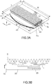
- the figure 3A represents a perspective view of a CTS antenna, and the figure 3B a section along the XZ plane.
- the antenna CTS consists of a source 10, which may be an inlet horn, a parallel plate waveguide 20, a pillbox junction 23, a tundish 1, and horn cones. 5.
- the width (dimension along the Y axis) of the longitudinal radiation horns 5 and the tundish 1 is generally equal to that of the pillbox trainer along this same axis.
- the waves emitted by the central source are indeed little or not reflected on the edges of the splitter 1, so few reflections occur on the edges of the splitter 1.
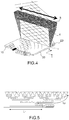
- the figure 4 schematically illustrates, according to an exploded view, the CTS antenna described in the document "Continous Transverse Stub Array for Ka-Band Applications” (Ettore et al., IEEE Transactions on antennas and propagation, Vol 63, No. 11, November 2015 ), and equipped with several sources 10 1 , 10 2 , ..., 10 M ,
- the use of several sources 10 can generate as many separate and simultaneous signals that propagate in different directions but coplanar, in the Xy plane inside the guide of parallel plate waves 20, then in the XZ plane in the tundish 1 and after emission by the longitudinal radiation horns 5.
- the plurality of sources 10 can thus simultaneously cover separate areas of the earth's surface.
- the use of a plurality of input sources 10 in the aforementioned CTS antenna has limitations.
- the pillbox junction 23 comprises only one focus.
- the focus is only perfect for a source placed at the focus of the reflector, defocus aberrations occur for sources remote from the focus of the reflector. These aberrations are the result of imperfect conversion of cylindrical waves into plane waves by the pillbox trainer.
- the wave emitted by an eccentric source 10 and reflected by the pillbox junction 23 in a very remote direction propagates obliquely in the splitter 1.
- This oversize 4 of the splitter 1 which causes an oversizing of longitudinal radiation horns 5 along the same axis, has a cost in terms of onboard weight, especially in a satellite. It also depends on the target maximum aiming angle and the propagation length in the splitter 1. It is all the more important that coverage is required over a wide angular sector along the axis of the main dimension of longitudinal horns 5, and that the electrical length of the distributor 1 is important.
- the aim of the invention is therefore to avoid oversizing the distributor and the radiating aperture along the longitudinal axis of the radiating aperture, due to the waves emitted by eccentric input sources with respect to the focus of the beamformer quasi-optical.
- the invention also aims, in some embodiments, to avoid imperfect focusing of the depointed beams.
- An object of the invention is therefore a quasi-optical beamformer comprising a power distributor composed of a succession of parallel plate dividers according to a tree structure with stages extending along a YZ plane of a first stage to a last stage, the parallel plates of said dividers each having a main dimension along an axis X orthogonal to the YZ plane, each parallel plate divider comprising, on each of the stages of the tree structure situated under an upper stage, a first and a second parallel plate waveguide branch leading to respective parallel plate dividers of the next stage of the tree structure, the beamformer further comprising a plurality of lenses extending longitudinally along the X axis over at least one stage of the power distributor, so as to apply a continuous variable delay along the X axis, and arranged in each do branches of the dividers of at least one stage of the power splitter.
- the lenses are arranged on a plurality of stages of the power splitter and have respective heights such that the continuous variable delay is applied progressively to the stages of the power splitter.
- the lenses are arranged at each stage of the power splitter.
- the lenses are only arranged on the last stage of the power splitter.
- each of the lenses of the same stage is a straight profile lens.
- each of the lenses of the same stage is a curvilinear profile lens.
- the power splitter comprises only straight profile lenses, arranged at each stage of the power splitter.
- the formatter is connected to a plurality of sources oriented in different directions along the XY plane, each of the sources being able to inject a wave into the splitter, the waves propagating respectively along said different directions along the XY plane, the lenses being adapted to collimate these waves.
- the invention also relates to a multibeam antenna comprising at least one quasi-optical beamformer as described above, and further comprising a plurality of horns of radiation, each horn of radiation being connected to a branch of the last stage of the tundish power.
- the multibeam antenna comprises a polarizer configured to circularly polarize the waves emitted by the antenna in a linear polarization.
- the Figure 6A illustrates a first embodiment, in which the wave conversion is performed on the last stage of the splitter 1.
- the sources 10 emit waves, with cylindrical wave fronts, to the power splitter 1.
- the power splitter 1 is composed a plurality of stages e 1 , ..., e N.
- e 1 directly connected sources 10 possibly via a straight bend at 90 °, is a parallel plate divider 3, consisting of two branches B1 and B2. It should be noted that the right elbow does not add extra lengths in the trainer, that's why the right elbows have no impact on the structure.
- the parallel plate divider 3 is configured to distribute the electric field E from the sources 10.
- the parallel plate dividers 3 may be unbalanced in order to modify the division of the power and thus control the distribution of the power at the horns 5.
- the right profile lens 6 may comprise an excrescence 13 provided with an insert 17, for example metal, disposed between the parallel plates of each of the branches B1 and B2, just before the horns 5.
- the dimensions of the outgrowth can be defined by a variation of the height of the insert along the y axis (see Figure 1B ).
- the height of the protrusion 13 may be zero or almost zero at the ends of the lens along the axis X, while it may be maximum in the center of the lens along the same axis.
- the insert can be in particular in the form of "I".
- the splitter 1 divides at each stage e 1 , ..., e N the electric field E of the waves, whose wavefront remains cylindrical in the splitter.
- This distribution of the cylindrical waves generates much less reflections on the edges of the splitter 1 for the waves from the most remote sources, compared to the CTS antenna of the state of the art.
- cylindrical (in the formator) and then plane (in the distributor) waves propagate over a great distance (length of the trainer added to the length of the splitter), while according to the invention, the waves propagate in the splitter directly from the sources, only over a length corresponding to that of the beamformer. The propagation distance of the waves is therefore shorter.
- the straight profile lenses 6, which comprise only one protrusion, have a reduced dimension along the Z axis; thus, it has a low profile along the same axis.
- This embodiment requires a certain spacing between the horns 5, along the y-axis, due to the height of the straight-profile lenses 6.
- the Figure 7A illustrates a second embodiment, wherein the wave conversion is performed on the last stage of the splitter 1.
- the sources 10 emit cylindrical waves, in the power splitter 1.
- the power splitter 1 is composed of a plurality of stages e 1 , ..., e N.
- e 1 directly connected to the sources 10 possibly via a 90 ° elbow, is a parallel plate divider 3, composed of two branches B1 and B2.
- the parallel plate divider 3 is configured to distribute the electric field E from the sources 10.
- On the last stage of the distributor at the output of each divider of this stage, possibly connected via a 90 ° elbow, is a curvilinear profile lens. 7.
- the waves propagate in the splitter directly from the sources, only over a length corresponding to that of the beamformer.
- a surface gain along the X axis is obtained vis-à-vis the CTS antenna of the state of the art. Furthermore, by adding a degree of freedom with respect to the first embodiment, it is thus possible to provide the beamformer with a plurality of focal points.
- the conversion of the cylindrical waves is done only at the last stage e N. Therefore, the height (along the y axis) of certain protuberances of the curvilinear profile lens imposes a spacing between the horns 5.
- the spacing between the horns 5 is imposed by the height lenses, as for the first embodiment described above.
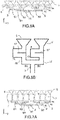
- the Figures 7B and 7C illustrate two cuts, according to the YZ plane, of curvilinear profile lenses 7 arranged at the last stage of the distributor, at two different locations of the lens 7 along the X axis.
- the curvilinear profile lens 7 is arranged between the parallel plates of each of the branches B1 and B2, just before the horns 5.
- the curvilinear profile lens 7 may comprise a protrusion 13, folded on itself, having a portion p 1 extending along the axis Y, a portion p 2 extending along the axis Z, and a portion p 3 extending along the axis Y.
- the spacing distance d between the two folded portions p 1 and p 3 which extend along the Y axis increases from the ends of the lens along the X axis ( Figure 7B ), to reach a maximum in the center of the lens ( Figure 7C ).
- the height of the growth along the y axis also varies; it can be zero or almost zero at the ends of the lens along the X axis, while it can be maximum at the center of the lens along the same axis.
- the figure 8 illustrates such an antenna, in particular the power distributor 1, the lenses 7 and the horns 5. It appears that this antenna is much less compact, along the Z axis, than that of the first embodiment because of the dimensions of the lenses with curvilinear profile 7.
- the figure 9 illustrates a third embodiment of the invention.
- the sources 10 emit cylindrical waves to the power splitter 1.
- the power splitter 1 is composed of a plurality of stages e 1 , ..., e N.
- a parallel plate divider 3 composed of two branches B1 and B2.
- the parallel plate divider 3 is configured to distribute the electric field E from the sources 10.
- the lenses used in the third embodiment can take the form of straight profile lenses comprising a protuberance (see FIG. Figure 1B ), at each of the branches B1, B2 of each divider.
- a parallel plate divider 3 is connected to the first branch B1. It comprises itself two branches B1 and B2, each of the branches B1 and B2 of this parallel plate divider 3 also comprising a straight profile lens 6.
- the splitter 1 is thus defined by a tree structure, where the right profile lenses are found at each stage of the splitter 1 on the branches B1 and B2.
- the protrusion may be integrated at the junction of branches B1 and B2; the contour of the junction is then no longer rectilinear, and must be modified so as to integrate the delay to be achieved by the protrusion.
- the waves propagate in the splitter directly from the sources, only over a length corresponding to that of the beamformer.
- a surface gain along the X axis is also obtained vis-à-vis the CTS antenna of the state of the art.
- Such an arrangement provides misalignment performance similar to the second embodiment, and therefore much better than the beamformers of the state of the art.
- the conversion to plane waves being made gradually, there are no reflections on the edges of the splitter 1, in contrast to the case where there are flat waves steeply inclined in the splitter 1.
- the multiplicity of excrescences allows to distribute and split, between the different growths, the delays to achieve, and thus obtain a delay gradient, namely a delay depending on the position of the wave along the Z axis.
- this increase in the number of degrees of freedom with respect to the first embodiment thus avoids the aberrations related to waves from highly detuned sources over a wide angular sector. It is thus possible to provide the beamformer with a plurality of focal points.
- the distribution of the lenses 6 makes it possible to reduce the amplitude of the delays to be made at each outgrowth, and therefore to limit the size thereof.
- the third mode has been described with straight profile lenses 6.
- This thus includes the pillbox junctions, which are a certain type of lens to straight profile, as previously described.
- It may also be envisaged to distribute curvilinear lens 7 (see FIG. Figures 1C and 1D ) in the splitter according to the third embodiment, taking into account, however, the bulk of the curvilinear profile lenses 7.
- Such a progressively distributed arrangement of curvilinear profile lenses 7 according to the third embodiment makes it possible to add additional degrees of freedom in the case where the use of straight profile lenses would not have enough for good performance.
- each horn of radiation 5 being connected to a branch (B1, B2) of the last stage of the power splitter e N.
- Each radiation horn 5 is configured to radiate the same field.
- the horns 5 may have different power levels to reduce the level of the grating lobes.
- the beams thus generated are refined in the plane E, and can be circular, so as to be particularly adapted to spatial telecommunications.
- the conversion being progressive, the delay to be applied to the last stage e N in this embodiment is less than that applied in FIG. the two previous modes.
- the low height of the lenses 6 (along the y axis) at the last stage e N allows the horns 5 to be sufficiently close to one another along the y axis, and thus to limit the problems generated by the lobes of networks.
- the heights of each of the lenses of the branches B1, B2 of the same stage are identical, so that the delay is uniformly and equitably applied to each stage, and that the different beams transmitted to the horns are in phase, thus improving the quality of the beams on a given angular sector.
- the antenna object of the invention advantageously comprises a polarizer configured to circularly polarize the waves emitted by the antenna in a linear polarization.
- a so-called septum polarizer can be integrated into the antenna; alternatively, a polarizing radome 18, shown schematically in FIG. figure 9 can cover the antenna according to the invention.
Landscapes
- Physics & Mathematics (AREA)
- Engineering & Computer Science (AREA)
- Astronomy & Astrophysics (AREA)
- General Physics & Mathematics (AREA)
- Remote Sensing (AREA)
- Aviation & Aerospace Engineering (AREA)
- Aerials With Secondary Devices (AREA)
- Variable-Direction Aerials And Aerial Arrays (AREA)
Applications Claiming Priority (1)
| Application Number | Priority Date | Filing Date | Title |
|---|---|---|---|
| FR1700799A FR3069713B1 (fr) | 2017-07-27 | 2017-07-27 | Antenne integrant des lentilles a retard a l'interieur d'un repartiteur a base de diviseurs a guide d'ondes a plaques paralleles |
Publications (2)
| Publication Number | Publication Date |
|---|---|
| EP3435480A1 true EP3435480A1 (de) | 2019-01-30 |
| EP3435480B1 EP3435480B1 (de) | 2020-02-19 |
Family
ID=60765648
Family Applications (1)
| Application Number | Title | Priority Date | Filing Date |
|---|---|---|---|
| EP18185469.6A Active EP3435480B1 (de) | 2017-07-27 | 2018-07-25 | Antenne mit integrierten verzögerungslinsen im innern eines verteilers auf der basis von wellenleiterteilern mit parallelen platten |
Country Status (6)
| Country | Link |
|---|---|
| US (1) | US10553957B2 (de) |
| EP (1) | EP3435480B1 (de) |
| CA (1) | CA3012540A1 (de) |
| DK (1) | DK3435480T3 (de) |
| ES (1) | ES2787050T3 (de) |
| FR (1) | FR3069713B1 (de) |
Families Citing this family (5)
| Publication number | Priority date | Publication date | Assignee | Title |
|---|---|---|---|---|
| CN114040722B (zh) | 2019-08-29 | 2025-01-28 | 圣犹达医疗用品心脏病学部门有限公司 | 包括密封电极尖端组件的力传感导管及其组装方法 |
| EP3958396B1 (de) * | 2020-08-18 | 2022-09-14 | The Boeing Company | Mehrsystem-mehrband-antennenanordnung mit rotman-linse |
| CN113517571B (zh) * | 2021-04-06 | 2023-02-14 | 浙江大学 | 一种基于多层矩形波导功分结构的cts天线 |
| EP4519943A4 (de) * | 2022-05-03 | 2026-04-15 | Univ Notre Dame Du Lac | Integrationsfreundliche flache planare grin-linsenantennen für tragbare millimeterwellenvorrichtungen |
| CN115117616B (zh) * | 2022-08-25 | 2022-12-02 | 成都国恒空间技术工程股份有限公司 | 一种基于rgw结构的victs天线 |
Citations (1)
| Publication number | Priority date | Publication date | Assignee | Title |
|---|---|---|---|---|
| US20060202899A1 (en) * | 2005-03-08 | 2006-09-14 | Raytheon Company | True-time-delay feed network for CTS array |
Family Cites Families (4)
| Publication number | Priority date | Publication date | Assignee | Title |
|---|---|---|---|---|
| US3170158A (en) * | 1963-05-08 | 1965-02-16 | Rotman Walter | Multiple beam radar antenna system |
| US5936588A (en) * | 1998-06-05 | 1999-08-10 | Rao; Sudhakar K. | Reconfigurable multiple beam satellite phased array antenna |
| FR3038457B1 (fr) * | 2015-07-03 | 2017-07-28 | Thales Sa | Formateur de faisceaux quasi-optique a lentille et antenne plane comportant un tel formateur de faisceaux |
| FR3044832B1 (fr) * | 2015-12-04 | 2018-01-05 | Thales | Architecture d'antenne active a formation de faisceaux hybride reconfigurable |
-
2017
- 2017-07-27 FR FR1700799A patent/FR3069713B1/fr not_active Expired - Fee Related
-
2018
- 2018-07-25 EP EP18185469.6A patent/EP3435480B1/de active Active
- 2018-07-25 ES ES18185469T patent/ES2787050T3/es active Active
- 2018-07-25 DK DK18185469.6T patent/DK3435480T3/da active
- 2018-07-26 US US16/046,920 patent/US10553957B2/en active Active
- 2018-07-26 CA CA3012540A patent/CA3012540A1/en active Pending
Patent Citations (1)
| Publication number | Priority date | Publication date | Assignee | Title |
|---|---|---|---|---|
| US20060202899A1 (en) * | 2005-03-08 | 2006-09-14 | Raytheon Company | True-time-delay feed network for CTS array |
Non-Patent Citations (2)
| Title |
|---|
| ETTORRE MAURO ET AL: "A compact and high-gain Ka-band multibeam continuous transverse stub antenna", 2015 IEEE INTERNATIONAL SYMPOSIUM ON ANTENNAS AND PROPAGATION & USNC/URSI NATIONAL RADIO SCIENCE MEETING, IEEE, 19 July 2015 (2015-07-19), pages 671 - 672, XP032796430, DOI: 10.1109/APS.2015.7304722 * |
| LU XIANLONG ET AL: "Beam-Scanning Continuous Transverse Stub Antenna Fed by a Ridged Waveguide Slot Array", IEEE ANTENNAS AND WIRELESS PROPAGATION LETTERS, vol. 16, 6 February 2017 (2017-02-06), pages 1675 - 1678, XP011653102, ISSN: 1536-1225, [retrieved on 20170619], DOI: 10.1109/LAWP.2017.2664880 * |
Also Published As
| Publication number | Publication date |
|---|---|
| DK3435480T3 (da) | 2020-05-18 |
| ES2787050T3 (es) | 2020-10-14 |
| FR3069713B1 (fr) | 2019-08-02 |
| FR3069713A1 (fr) | 2019-02-01 |
| US20190036228A1 (en) | 2019-01-31 |
| US10553957B2 (en) | 2020-02-04 |
| CA3012540A1 (en) | 2019-01-27 |
| EP3435480B1 (de) | 2020-02-19 |
Similar Documents
| Publication | Publication Date | Title |
|---|---|---|
| EP3435480B1 (de) | Antenne mit integrierten verzögerungslinsen im innern eines verteilers auf der basis von wellenleiterteilern mit parallelen platten | |
| EP3547450B1 (de) | Strahlungselement mit kreispolarisierung, bei dem eine resonanz in einem fabry-perot-interferometer angewandt wird | |
| EP0205212B1 (de) | Modulare Mikrowellenantenneneinheiten und Antenne mit solchen Einheiten | |
| EP2564466B1 (de) | Kompaktes strahlungselement mit hohlraumresonatoren | |
| EP2194602B1 (de) | Antenne mit gemeinsam benützten Elementarstrahlern und Verfahren zum Entwurf einer Mehrstrahlantenne mit gemeinsam benützten Elementarstrahlern | |
| EP3179551B1 (de) | Kompakteinheit zur doppelpolarisierten ansteuerung für ein strahlungselement einer antenne, und kompaktes netz, das mindestens vier kompakte ansteuerungseinheiten umfasst | |
| WO2011095384A1 (fr) | Antenne plane à balayage pour application mobile terrestre, véhicule comportant une telle antenne et système de télécommunication par satellite comportant un tel véhicule | |
| EP2869400A1 (de) | Doppelpolarisierter kompakter Leistungsverteiler, Netz aus mehreren Verteilern, kompaktes Strahlungselement und Flachantenne, die einen solchen Verteiler umfasst | |
| EP3113286B1 (de) | Quasioptischer strahlformer mit linse, und flachantenne, die einen solchen strahlformer umfasst | |
| EP2869396A1 (de) | Leistungsverteiler, der eine T-Kupplung auf der E-Ebene umfasst, Speisenetzwerk und Antenne, die ein solches Speisenetzwerk umfasst | |
| EP3176875B1 (de) | Aufbau einer aktiven hybriden rekonfigurierbaren strahlbildungsantenne | |
| FR3035546A1 (fr) | Module structural d'antenne integrant des sources rayonnantes elementaires a orientation individuelle, panneau rayonnant, reseau rayonnant et antenne multifaisceaux comportant au moins un tel module | |
| EP0430745A1 (de) | Zirkular polarisierte Antenne, insbesondere für Gruppenantenne | |
| FR2904478A1 (fr) | Dispositif de transduction orthomode a compacite optimisee dans le plan de maille, pour une antenne | |
| EP3664214B1 (de) | Mehrfachzugriff strahlelemente | |
| EP4523291A1 (de) | Flache antenne mit zweidimensionaler elektronischer abtastung | |
| EP1522119B1 (de) | Phasenschieber fähig zur kontinuierlichen phasenänderung | |
| EP3220181B1 (de) | Hybrides optisches system mit reduzierter grösse für abbildungsgruppenantenne | |
| EP0337841A1 (de) | Unsymmetrisch gespeiste breitbandige Sendeantennenschleife und Antennenfeld aus einer Vielzahl dieser Schleifen | |
| EP3155689B1 (de) | Flachantenne zur satellitenkommunikation | |
| FR3108797A1 (fr) | Antenne directive large bande à émission longitudinale | |
| EP0407258B1 (de) | Direkt strahlender Verteiler von Höchstfrequenzenergie | |
| EP4207493B1 (de) | Passive direktionale hf-antenne mit ein- oder zweidimensionaler abtastung | |
| EP3075031B1 (de) | Anordnung von antennenstrukturen für satellitentelekommunikationen |
Legal Events
| Date | Code | Title | Description |
|---|---|---|---|
| PUAI | Public reference made under article 153(3) epc to a published international application that has entered the european phase |
Free format text: ORIGINAL CODE: 0009012 |
|
| STAA | Information on the status of an ep patent application or granted ep patent |
Free format text: STATUS: THE APPLICATION HAS BEEN PUBLISHED |
|
| AK | Designated contracting states |
Kind code of ref document: A1 Designated state(s): AL AT BE BG CH CY CZ DE DK EE ES FI FR GB GR HR HU IE IS IT LI LT LU LV MC MK MT NL NO PL PT RO RS SE SI SK SM TR |
|
| AX | Request for extension of the european patent |
Extension state: BA ME |
|
| STAA | Information on the status of an ep patent application or granted ep patent |
Free format text: STATUS: REQUEST FOR EXAMINATION WAS MADE |
|
| 17P | Request for examination filed |
Effective date: 20190523 |
|
| RBV | Designated contracting states (corrected) |
Designated state(s): AL AT BE BG CH CY CZ DE DK EE ES FI FR GB GR HR HU IE IS IT LI LT LU LV MC MK MT NL NO PL PT RO RS SE SI SK SM TR |
|
| GRAP | Despatch of communication of intention to grant a patent |
Free format text: ORIGINAL CODE: EPIDOSNIGR1 |
|
| STAA | Information on the status of an ep patent application or granted ep patent |
Free format text: STATUS: GRANT OF PATENT IS INTENDED |
|
| INTG | Intention to grant announced |
Effective date: 20191007 |
|
| GRAS | Grant fee paid |
Free format text: ORIGINAL CODE: EPIDOSNIGR3 |
|
| GRAA | (expected) grant |
Free format text: ORIGINAL CODE: 0009210 |
|
| STAA | Information on the status of an ep patent application or granted ep patent |
Free format text: STATUS: THE PATENT HAS BEEN GRANTED |
|
| AK | Designated contracting states |
Kind code of ref document: B1 Designated state(s): AL AT BE BG CH CY CZ DE DK EE ES FI FR GB GR HR HU IE IS IT LI LT LU LV MC MK MT NL NO PL PT RO RS SE SI SK SM TR |
|
| REG | Reference to a national code |
Ref country code: CH Ref legal event code: EP |
|
| REG | Reference to a national code |
Ref country code: DE Ref legal event code: R096 Ref document number: 602018002516 Country of ref document: DE |
|
| REG | Reference to a national code |
Ref country code: AT Ref legal event code: REF Ref document number: 1235998 Country of ref document: AT Kind code of ref document: T Effective date: 20200315 |
|
| REG | Reference to a national code |
Ref country code: IE Ref legal event code: FG4D Free format text: LANGUAGE OF EP DOCUMENT: FRENCH |
|
| REG | Reference to a national code |
Ref country code: DK Ref legal event code: T3 Effective date: 20200514 |
|
| REG | Reference to a national code |
Ref country code: SE Ref legal event code: TRGR |
|
| REG | Reference to a national code |
Ref country code: NL Ref legal event code: MP Effective date: 20200219 |
|
| PG25 | Lapsed in a contracting state [announced via postgrant information from national office to epo] |
Ref country code: NO Free format text: LAPSE BECAUSE OF FAILURE TO SUBMIT A TRANSLATION OF THE DESCRIPTION OR TO PAY THE FEE WITHIN THE PRESCRIBED TIME-LIMIT Effective date: 20200519 Ref country code: FI Free format text: LAPSE BECAUSE OF FAILURE TO SUBMIT A TRANSLATION OF THE DESCRIPTION OR TO PAY THE FEE WITHIN THE PRESCRIBED TIME-LIMIT Effective date: 20200219 Ref country code: RS Free format text: LAPSE BECAUSE OF FAILURE TO SUBMIT A TRANSLATION OF THE DESCRIPTION OR TO PAY THE FEE WITHIN THE PRESCRIBED TIME-LIMIT Effective date: 20200219 |
|
| REG | Reference to a national code |
Ref country code: LT Ref legal event code: MG4D |
|
| PG25 | Lapsed in a contracting state [announced via postgrant information from national office to epo] |
Ref country code: LV Free format text: LAPSE BECAUSE OF FAILURE TO SUBMIT A TRANSLATION OF THE DESCRIPTION OR TO PAY THE FEE WITHIN THE PRESCRIBED TIME-LIMIT Effective date: 20200219 Ref country code: IS Free format text: LAPSE BECAUSE OF FAILURE TO SUBMIT A TRANSLATION OF THE DESCRIPTION OR TO PAY THE FEE WITHIN THE PRESCRIBED TIME-LIMIT Effective date: 20200619 Ref country code: HR Free format text: LAPSE BECAUSE OF FAILURE TO SUBMIT A TRANSLATION OF THE DESCRIPTION OR TO PAY THE FEE WITHIN THE PRESCRIBED TIME-LIMIT Effective date: 20200219 Ref country code: BG Free format text: LAPSE BECAUSE OF FAILURE TO SUBMIT A TRANSLATION OF THE DESCRIPTION OR TO PAY THE FEE WITHIN THE PRESCRIBED TIME-LIMIT Effective date: 20200519 Ref country code: GR Free format text: LAPSE BECAUSE OF FAILURE TO SUBMIT A TRANSLATION OF THE DESCRIPTION OR TO PAY THE FEE WITHIN THE PRESCRIBED TIME-LIMIT Effective date: 20200520 |
|
| PG25 | Lapsed in a contracting state [announced via postgrant information from national office to epo] |
Ref country code: NL Free format text: LAPSE BECAUSE OF FAILURE TO SUBMIT A TRANSLATION OF THE DESCRIPTION OR TO PAY THE FEE WITHIN THE PRESCRIBED TIME-LIMIT Effective date: 20200219 |
|
| REG | Reference to a national code |
Ref country code: ES Ref legal event code: FG2A Ref document number: 2787050 Country of ref document: ES Kind code of ref document: T3 Effective date: 20201014 |
|
| PG25 | Lapsed in a contracting state [announced via postgrant information from national office to epo] |
Ref country code: SM Free format text: LAPSE BECAUSE OF FAILURE TO SUBMIT A TRANSLATION OF THE DESCRIPTION OR TO PAY THE FEE WITHIN THE PRESCRIBED TIME-LIMIT Effective date: 20200219 Ref country code: EE Free format text: LAPSE BECAUSE OF FAILURE TO SUBMIT A TRANSLATION OF THE DESCRIPTION OR TO PAY THE FEE WITHIN THE PRESCRIBED TIME-LIMIT Effective date: 20200219 Ref country code: RO Free format text: LAPSE BECAUSE OF FAILURE TO SUBMIT A TRANSLATION OF THE DESCRIPTION OR TO PAY THE FEE WITHIN THE PRESCRIBED TIME-LIMIT Effective date: 20200219 Ref country code: LT Free format text: LAPSE BECAUSE OF FAILURE TO SUBMIT A TRANSLATION OF THE DESCRIPTION OR TO PAY THE FEE WITHIN THE PRESCRIBED TIME-LIMIT Effective date: 20200219 Ref country code: CZ Free format text: LAPSE BECAUSE OF FAILURE TO SUBMIT A TRANSLATION OF THE DESCRIPTION OR TO PAY THE FEE WITHIN THE PRESCRIBED TIME-LIMIT Effective date: 20200219 Ref country code: SK Free format text: LAPSE BECAUSE OF FAILURE TO SUBMIT A TRANSLATION OF THE DESCRIPTION OR TO PAY THE FEE WITHIN THE PRESCRIBED TIME-LIMIT Effective date: 20200219 Ref country code: PT Free format text: LAPSE BECAUSE OF FAILURE TO SUBMIT A TRANSLATION OF THE DESCRIPTION OR TO PAY THE FEE WITHIN THE PRESCRIBED TIME-LIMIT Effective date: 20200712 |
|
| REG | Reference to a national code |
Ref country code: AT Ref legal event code: MK05 Ref document number: 1235998 Country of ref document: AT Kind code of ref document: T Effective date: 20200219 |
|
| REG | Reference to a national code |
Ref country code: DE Ref legal event code: R097 Ref document number: 602018002516 Country of ref document: DE |
|
| PLBE | No opposition filed within time limit |
Free format text: ORIGINAL CODE: 0009261 |
|
| STAA | Information on the status of an ep patent application or granted ep patent |
Free format text: STATUS: NO OPPOSITION FILED WITHIN TIME LIMIT |
|
| 26N | No opposition filed |
Effective date: 20201120 |
|
| PG25 | Lapsed in a contracting state [announced via postgrant information from national office to epo] |
Ref country code: AT Free format text: LAPSE BECAUSE OF FAILURE TO SUBMIT A TRANSLATION OF THE DESCRIPTION OR TO PAY THE FEE WITHIN THE PRESCRIBED TIME-LIMIT Effective date: 20200219 |
|
| PG25 | Lapsed in a contracting state [announced via postgrant information from national office to epo] |
Ref country code: SI Free format text: LAPSE BECAUSE OF FAILURE TO SUBMIT A TRANSLATION OF THE DESCRIPTION OR TO PAY THE FEE WITHIN THE PRESCRIBED TIME-LIMIT Effective date: 20200219 Ref country code: MC Free format text: LAPSE BECAUSE OF FAILURE TO SUBMIT A TRANSLATION OF THE DESCRIPTION OR TO PAY THE FEE WITHIN THE PRESCRIBED TIME-LIMIT Effective date: 20200219 Ref country code: PL Free format text: LAPSE BECAUSE OF FAILURE TO SUBMIT A TRANSLATION OF THE DESCRIPTION OR TO PAY THE FEE WITHIN THE PRESCRIBED TIME-LIMIT Effective date: 20200219 |
|
| REG | Reference to a national code |
Ref country code: BE Ref legal event code: MM Effective date: 20200731 |
|
| PG25 | Lapsed in a contracting state [announced via postgrant information from national office to epo] |
Ref country code: LU Free format text: LAPSE BECAUSE OF NON-PAYMENT OF DUE FEES Effective date: 20200725 |
|
| PG25 | Lapsed in a contracting state [announced via postgrant information from national office to epo] |
Ref country code: BE Free format text: LAPSE BECAUSE OF NON-PAYMENT OF DUE FEES Effective date: 20200731 |
|
| PG25 | Lapsed in a contracting state [announced via postgrant information from national office to epo] |
Ref country code: IE Free format text: LAPSE BECAUSE OF NON-PAYMENT OF DUE FEES Effective date: 20200725 |
|
| REG | Reference to a national code |
Ref country code: CH Ref legal event code: PL |
|
| PG25 | Lapsed in a contracting state [announced via postgrant information from national office to epo] |
Ref country code: LI Free format text: LAPSE BECAUSE OF NON-PAYMENT OF DUE FEES Effective date: 20210731 Ref country code: CH Free format text: LAPSE BECAUSE OF NON-PAYMENT OF DUE FEES Effective date: 20210731 |
|
| PG25 | Lapsed in a contracting state [announced via postgrant information from national office to epo] |
Ref country code: TR Free format text: LAPSE BECAUSE OF FAILURE TO SUBMIT A TRANSLATION OF THE DESCRIPTION OR TO PAY THE FEE WITHIN THE PRESCRIBED TIME-LIMIT Effective date: 20200219 Ref country code: MT Free format text: LAPSE BECAUSE OF FAILURE TO SUBMIT A TRANSLATION OF THE DESCRIPTION OR TO PAY THE FEE WITHIN THE PRESCRIBED TIME-LIMIT Effective date: 20200219 Ref country code: CY Free format text: LAPSE BECAUSE OF FAILURE TO SUBMIT A TRANSLATION OF THE DESCRIPTION OR TO PAY THE FEE WITHIN THE PRESCRIBED TIME-LIMIT Effective date: 20200219 |
|
| PG25 | Lapsed in a contracting state [announced via postgrant information from national office to epo] |
Ref country code: MK Free format text: LAPSE BECAUSE OF FAILURE TO SUBMIT A TRANSLATION OF THE DESCRIPTION OR TO PAY THE FEE WITHIN THE PRESCRIBED TIME-LIMIT Effective date: 20200219 Ref country code: AL Free format text: LAPSE BECAUSE OF FAILURE TO SUBMIT A TRANSLATION OF THE DESCRIPTION OR TO PAY THE FEE WITHIN THE PRESCRIBED TIME-LIMIT Effective date: 20200219 |
|
| P01 | Opt-out of the competence of the unified patent court (upc) registered |
Effective date: 20230517 |
|
| PGFP | Annual fee paid to national office [announced via postgrant information from national office to epo] |
Ref country code: SE Payment date: 20250626 Year of fee payment: 8 |
|
| PGFP | Annual fee paid to national office [announced via postgrant information from national office to epo] |
Ref country code: ES Payment date: 20250804 Year of fee payment: 8 |
|
| PGFP | Annual fee paid to national office [announced via postgrant information from national office to epo] |
Ref country code: DK Payment date: 20250714 Year of fee payment: 8 Ref country code: DE Payment date: 20250618 Year of fee payment: 8 |
|
| PGFP | Annual fee paid to national office [announced via postgrant information from national office to epo] |
Ref country code: IT Payment date: 20250626 Year of fee payment: 8 |
|
| PGFP | Annual fee paid to national office [announced via postgrant information from national office to epo] |
Ref country code: GB Payment date: 20260622 Year of fee payment: 9 |
|
| PGFP | Annual fee paid to national office [announced via postgrant information from national office to epo] |
Ref country code: FR Payment date: 20260629 Year of fee payment: 9 |