EP3438559A1 - Klimaanlageninnenraumeinheit - Google Patents
Klimaanlageninnenraumeinheit Download PDFInfo
- Publication number
- EP3438559A1 EP3438559A1 EP17895510.0A EP17895510A EP3438559A1 EP 3438559 A1 EP3438559 A1 EP 3438559A1 EP 17895510 A EP17895510 A EP 17895510A EP 3438559 A1 EP3438559 A1 EP 3438559A1
- Authority
- EP
- European Patent Office
- Prior art keywords
- drain pan
- drain
- indoor unit
- heat exchanger
- water
- Prior art date
- Legal status (The legal status is an assumption and is not a legal conclusion. Google has not performed a legal analysis and makes no representation as to the accuracy of the status listed.)
- Granted
Links
Images








Classifications
-
- F—MECHANICAL ENGINEERING; LIGHTING; HEATING; WEAPONS; BLASTING
- F24—HEATING; RANGES; VENTILATING
- F24F—AIR-CONDITIONING; AIR-HUMIDIFICATION; VENTILATION; USE OF AIR CURRENTS FOR SCREENING
- F24F13/00—Details common to, or for air-conditioning, air-humidification, ventilation or use of air currents for screening
- F24F13/22—Means for preventing condensation or evacuating condensate
- F24F13/222—Means for preventing condensation or evacuating condensate for evacuating condensate
-
- F—MECHANICAL ENGINEERING; LIGHTING; HEATING; WEAPONS; BLASTING
- F24—HEATING; RANGES; VENTILATING
- F24F—AIR-CONDITIONING; AIR-HUMIDIFICATION; VENTILATION; USE OF AIR CURRENTS FOR SCREENING
- F24F1/00—Room units for air-conditioning, e.g. separate or self-contained units or units receiving primary air from a central station
- F24F1/0007—Indoor units, e.g. fan coil units
- F24F1/0059—Indoor units, e.g. fan coil units characterised by heat exchangers
- F24F1/0063—Indoor units, e.g. fan coil units characterised by heat exchangers by the mounting or arrangement of the heat exchangers
-
- F—MECHANICAL ENGINEERING; LIGHTING; HEATING; WEAPONS; BLASTING
- F24—HEATING; RANGES; VENTILATING
- F24F—AIR-CONDITIONING; AIR-HUMIDIFICATION; VENTILATION; USE OF AIR CURRENTS FOR SCREENING
- F24F13/00—Details common to, or for air-conditioning, air-humidification, ventilation or use of air currents for screening
- F24F13/22—Means for preventing condensation or evacuating condensate
- F24F13/222—Means for preventing condensation or evacuating condensate for evacuating condensate
- F24F2013/227—Condensate pipe for drainage of condensate from the evaporator
-
- F—MECHANICAL ENGINEERING; LIGHTING; HEATING; WEAPONS; BLASTING
- F24—HEATING; RANGES; VENTILATING
- F24F—AIR-CONDITIONING; AIR-HUMIDIFICATION; VENTILATION; USE OF AIR CURRENTS FOR SCREENING
- F24F2221/00—Details or features not otherwise provided for
- F24F2221/22—Cleaning ducts or apparatus
Definitions
- the present invention relates to an indoor unit for an air conditioner.
- An indoor unit for an air conditioner conditions indoor air by: suctioning the indoor air into the indoor unit; applying a selected one of heating, cooling and dehumidifying processes to the suctioned indoor air by passing the suctioned indoor air through a heat exchanger to obtain the conditioned air; and blowing out the obtained conditioned air into the building.
- a filter is arranged closing a clearance between an air suction port for suctioning the indoor air and the heat exchanger in order to prevent dust included in the indoor air from entering the inside of the indoor unit, and the filter collects most of the dust. Fine dust smaller than the mesh size of the filter still passes through the mesh of the filter, and enters the inside of the indoor unit.
- the dust adhering to the heat exchanger contains components which are nutrients for bacteria (including molds) .
- components which are nutrients for bacteria including molds.
- each time the air conditioner performs a cooling or dehumidifying operation in the summer moisture in the air condenses on fins of the heat exchanger, and the ambient atmosphere around the heat exchanger becomes highly humid. Continuous adhering of the dust to the heat exchanger, therefore, grows the bacteria, and is likely to generate foul smell. In view of this, it is desirable that the air conditioner remove the dust adhering to the heat exchanger to keep the heat exchanger clean throughout the year.
- Patent Literature 1 has proposed an air conditioner which performs a heating operation and thereafter a cooling or dehumidifying operation to make water adhere to the surfaces of the fins of the heat exchanger, and washes down the dust including the oil, which adheres to the surfaces of the fins, using the adhering water.
- the air conditioner described in Patent Literature 1 requires an anti-dirt treatment to be applied to the surfaces of the fins in order to wash down the dust using the water adhering to the surfaces of the fins.
- frost or ice is made to adhere to the surfaces of the fins by an operation of decreasing the temperature of the heat exchanger; thereafter, the frost or ice is melted by an operation of raising the temperature of the heat exchanger; and the dust adhering to the heat exchanger is washed down using momentum with which the melted water flows down.
- the process of washing the heat exchanger in this way will be hereinafter referred to as "freeze washing.”
- This freeze washing can make a large amount of frost (including ice) adhere to the surfaces of the fins per unit time, which is larger than an amount of water a normal cooling or dehumidifying operation makes adhere to the surfaces of the fins per unit time.
- This freeze washing therefore, can wash down the dust adhering to the heat exchanger without applying the anti-dirt treatment to the surfaces of the fins.
- Patent Literature 1 Japanese Patent Application Publication No. 2008-138913
- the freeze washing produces a large amount of water (drain water) per unit time, which is larger than an amount of water the normal cooling or dehumidifying operation does. It is desired that the air condition not leak the large amount of water (drain water) to the outside of the indoor unit.
- a main object of the present invention is to provide an indoor unit for an air conditioner which leaks no water to the outside of the indoor unit during the freeze washing.
- the present invention is an indoor unit for an air conditioner which is characterized in that the indoor unit includes: a heat exchanger for exchanging heat between air and refrigerant; a drain pan for receiving drain water which drops from the heat exchanger; and a controller for controlling a freezing operation of making frost or ice adhere to a surface of the heat exchanger.
- the indoor unit is further characterized in that a volume of the drain pan is equal to or greater than a total adhesion amount of frost or ice to adhere to the heat exchanger during the freezing operation.
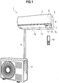
- FIG. 1 is a configuration diagram of the air conditioner 1 according to the first embodiment.
- FIG. 2 is a cross-sectional diagram of an indoor unit 2 of the air conditioner 1.
- the air conditioner 1 includes the indoor unit 2 placed inside a building, an outdoor unit 3 placed outside the building, and a remote controller 12 placed near a user inside the building.
- the indoor unit 2 conditions indoor air by: suctioning the indoor air into the indoor unit 2; applying a selected one of heating, cooling and dehumidifying processes to the suctioned indoor air by passing the suctioned indoor air through a heat exchanger 16 (see FIG. 2 ) ; obtaining the conditioned air; and blowing out the obtained conditioned air into the building.
- the indoor unit 2 is connected to the outdoor unit 3 through a connecting pipe 5, and circulates a refrigerant between the indoor unit 2 and the outdoor unit 3.
- the outdoor unit 3 exchanges heat between the air and the circulating refrigerant.
- the indoor unit 2 includes structural bodies such as an air blowing fan 14 (see FIG. 2 ) and the heat exchanger 16 (see FIG. 2 ) inside a housing 7 and a decorative frame 8.
- the air blowing fan 14 is a through-flow fan which sends air from an air inlet port 6 to an air outlet port 13.
- the heat exchanger 16 is a unit which exchanges heat between the air and the refrigerant.
- a front surface of the decorative frame 8 has a shape which: includes an upper portion extending in an up-down direction; and a lower portion whose low side extends slantingly toward a rear.
- a front panel 9 is attached to the upper portion of the front surface of the decorative frame 8.
- the front panel 9 is a member covering the front surface of the indoor unit 2.
- a receiver 10, a display 11, and an up-down wind direction board 18 are mounted in the lower portion of the front surface of the decorative frame 8.
- the receiver 10 is a device which receives operation signals sent from the remote controller 12.
- the receiver 10 is electrically connected to a controller CL built in the indoor unit 2.
- the controller CL controls operations and actions of the air conditioner 1 based on the operation signals received from the remote controller 12 via the receiver 10.
- the display 11 is a device which displays how the air conditioner 1 is operating.
- the up-down wind direction board 18 is a member for defining an up-down direction of the conditioned air which is blown out from the air outlet port 13.
- the up-down wind direction board 18 has a configuration in which: the up-down wind direction board 18 is pivotally supported near its lower end by the decorative frame 8 (or the housing 7) such that an upper portion of the up-down wind direction board 18 opens and closes in the up-down direction; and the up-down wind direction board 18 is turned by a driving section (not illustrated) .
- the indoor unit 2 forms the air outlet port 13 by opening the up-down wind direction board 18.
- the indoor unit 2 includes, in its inside, a filter 15, a drain pan 17 and a left-right wind direction board 19 in addition to the air flowing fan 14, the heat exchanger 16 and the up-down wind direction board 18.
- the filter 15 is a member for preventing dust from entering the inside of the housing 7.
- the drain pan 17 is a member for receiving drops of water (drain water) which condenses on the surfaces of fins 20 of the heat exchanger 16.
- the left-right wind direction board 19 is a member for defining a left-right direction of the conditioned air which is blown out from the air outlet port 13.
- the filter 15 is arranged in a way that closes a gap between the air inlet port 6 and the heat exchanger 16.
- the air conditioner 1 has a configuration in which: the filter 15 prevents dust larger than the mesh size of the filter 15 from entering the inside of the housing 7; and by freeze washing (described later), the air conditioner 1 washes away dust which passes through the mesh of the filter 15 because of being smaller than the mesh size of the filter 15.
- the air conditioner 1 preferably has a configuration including a filter cleaning mechanism (not illustrated), and may be capable of automatically cleaning the filter 15 using the filter cleaning mechanism (more preferably, on a regular basis).
- the air blowing fan 14 is arranged near a substantially central portion of the inside of the indoor unit 2 such that the air blowing fan 14 is capable of: suctioning the air from the air inlet port 6; and blowing out the air from the air outlet port 13.
- the heat exchanger 16 is arranged upstream of the air blowing fan 14 (on a side closer to the air inlet port 6), and is formed substantially in the shape of the letter V turned upside down to cover an upstream side of the air blowing fan 14.
- the heat exchanger 16 includes a front heat exchanger 16F and a rear heat exchanger 16R.
- the front heat exchanger 16F and the rear heat exchanger 16R each include multiple fins (heat exchange plates) 20, and multiple pipes 40 penetrating through the multiple fins 20.
- Each fin 20 is a long thin plate-shaped member for exchanging heat between the refrigerant and the air.
- the fin 20 is made from, for example, an aluminum alloy.
- Each pipe 40 is a member in which the refrigerant flows.
- the indoor unit 2 collects most of the dust from the indoor air suctioned into the indoor unit 2. Some of the dust, however, cannot be collected by the filter 15. Such dust passes through the mesh of the filter 15, and enters the inside of the indoor unit 2 to adhere to the heat exchanger 16. If such dust continues to adhere to the heat exchanger 16, there is likelihood that bacteria (including molds) grow and start to smell foul. With this taken into consideration, it is desirable that the air conditioner 1 be configured to remove dust which adheres to the heat exchanger 16. In this embodiment, therefore, the air conditioner 1 performs the following washing process on the heat exchanger 16 by controlling operations.
- the air conditioner 1 performs an action of making frost or ice adhere to the surfaces of the fins 20 of the heat exchanger 16 (hereinafter referred to as a "freezing action”) by performing an operation of decreasing the temperature of the heat exchanger 16 to cool the heat exchanger 16 quickly.
- a freezing operation an operation for the freezing action is referred to as a "freezing operation.”
- frost including ice
- the freezing operation sublimes moisture in the air to make frost (including ice) directly adhere to the surfaces of the fins 20 of the heat exchanger 16 without passing the moisture through a water droplet phase.
- moisture in the air condenses on the surfaces of the fins 20 of the heat exchanger 16, and the condensed moisture freezes thereon to make frost (ice) adhere to the surfaces of the fins 20 of the heat exchanger 16 after passing through a water droplet phase.
- the air conditioner 1 does not operate the air blowing fan 14 unlike during the normal cooling operation. This makes it possible for the air conditioner 1 to inhibit the dropping (falling) of water (condensed water) condensed on the surfaces of the fins 20 of the heat exchanger 16, and thereby to make the water (condensed water) stay on the surfaces of the fins 20 for a longer time.
- the air conditioner 1 can thus secure a stable amount of frozen water.
- the air conditioner 1 After the freezing operation, the air conditioner 1 performs an action of defrosting (melting) the frost (ice) (hereinafter referred to as a "melting action") by performing an operation of raising the temperature of the heat exchanger 16 to heat the heat exchanger 16 quickly.
- a melting action an operation for the melting action is referred to as a "melting operation.”
- the air conditioner 1 turns the frost (ice) back into water. While turning the frost (ice) back into water, the air conditioner 1 washes down fine dust adhering to the heat exchanger 16, using momentum with which the melted (defrosted) water drops down. This makes it possible for the air conditioner 1 to enhance the maintainability of the heat exchanger 16, and accordingly to wash the heat exchanger 16 efficiently.
- This washing process (the washing process performed by the freezing operation and the melting operation in combination) will be hereinafter referred to as a "freeze washing.”
- the air conditioner 1 receives water (drain water) which flows out during the melting operation.
- a flow passage in which the water (drain water) flows is formed in the drain pan 17.
- Mirror surface processing is applied to an inner wall surface of the flow passage in order to facilitate the flow of the water (drain water).
- a drain pipe is connected to the flow passage. The air conditioner 1 discharges the water (drain water) flowing out via the drain pipe, to the outside of the housing 7.
- FIGS. 3 to 6 descriptions will be provided for a configuration of the drain pan 17.
- the embodiment will discuss the configuration in which the drain pan 17 is integrally formed in the housing 7.
- FIG. 3 is a perspective diagram of a drain pan section in the housing 7.
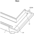
- FIG. 4 is a partially magnified diagram of a front drain pan 17F in the drain pan section.
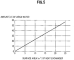
- FIG. 5 is a graphic diagram showing a relationship between a surface area of the heat exchanger 16 and an amount of drain water produced by the freeze washing.
- FIG. 6 is a schematic diagram illustrating an arrangement structure of a drain pipe 22 in the drain pan section.
- the drain pan 17 includes: a rear drain pan 17R arranged under the rear heat exchanger 16R (see FIG. 2 ); and a front drain pan 17F arranged under the front heat exchanger 16F (see FIG. 2 ).
- communicating passages 21a, 21b are provided in two sides of the rear drain pan 17R.
- drain pipes 22a, 22b are provided in two sides of the front drain pan 17F.
- the communicating passages 21a, 21b will be hereinafter generically referred to as a "communicating passage 21.”
- the drain pipes 22a, 22b will be hereinafter generically referred to as a "drain pipe 22.”
- the rear drain pan 17R receives water which drops from the rear heat exchanger 16R (see FIG. 2 ).
- a bottom surface of the rear drain pan 17R inclines downward from its part farthest from the communicating passage 21 toward its part nearest to the communicating passage 21.
- the bottom surface of the rear drain pan 17R has a shape in which: the bottom surface is highest around its substantially central portion in the left-right direction, and is lower in its left and right end portions than its substantially central portion.
- a bottom surface of the communicating passage 21 inclines downward from the rear drain pan 17R toward the front drain pan 17F.
- water dropping from the rear heat exchanger 16R flows out from the communicating passage 21 to the front drain pan 17F.
- the front drain pan 17F receives water dropping from the front heat exchanger 16F (see FIG. 2 ). Furthermore, water dropping from the rear heat exchanger 16R (see FIG. 2 ) flows into the front drain pan 17F from the rear drain pan 17R. Water dropping from the front heat exchanger 16F (see FIG. 2 ) and water dropping from the rear heat exchanger 16R (see FIG. 2 ) are discharged to the outside of the indoor unit 2 via the drain pipe 22. The water dropping from the front heat exchanger 16F (see FIG. 2 ) and the water dropping from the rear heat exchanger 16R (see FIG. 2 ) will be hereinafter generically referred to as "drain water.”
- the freezing operation makes a large amount of frost (or ice) adhere to the rear heat exchanger 16R and the front heat exchanger 16F per unit time, which is larger than an amount of water the normal cooling or dehumidifying operation makes adhere to the rear heat exchanger 16R and the front heat exchanger 16F per unit time.
- the frost (ice) having adhered to the rear heat exchanger 16R and the front heat exchanger 16F melts all at once during the melting operation.
- the large amount of drain water which is larger than the amount of water produced per unit time during the normal cooling or dehumidifying operation, is produced per unit time during the freezing operation.
- Such a large amount of drain water drops into the rear drain pan 17R and the front drain pan 17F all at once.
- the drain water would spill out of the front drain pan 17F or the rear drain pan 17R before the drain water is discharged to the outside of the indoor unit 2 via the drain pipes 22a, 22b. The drain water would thus leak to the outside of the indoor unit 2.
- the air conditioner 1 be designed not to allow the large amount of drain water produced during the melting operation to leak to the outside of the indoor unit 2. It is accordingly desirable that the drain pan 17 have a volume large enough not to allow the large amount of drain water produced during the melting operation to spill out of the drain pan 17.
- the indoor unit 2 is configured such that the volume of the whole drain pan 17 including the rear drain pan 17R and the front drain pan 17F is equal to or greater than a total adhesion amount of frost or ice to adhere to the heat exchanger 16 during the freezing operation.
- FIG. 5 illustrates a relationship between the surface area of the whole heat exchanger 16 including the rear heat exchanger 16R and the front heat exchanger 16F, and the amount of drain water produced during the freeze washing (a total adhesion amount of frost or ice) .
- FIG. 5 shows experimental results which were measured when the air conditioner 1 performed the freeze washing under conditions: an indoor temperature of 27 °C and an indoor humidity of 35%.
- 34.2 ml of drain water was produced in a case that the surface area of the whole heat exchanger 16 including the rear heat exchanger 16R and the front hear exchanger 16F was 15 m 2 .
- the indoor unit 2 allows the volume of the drain pan 17 to be set at a value y 1 obtained by subtracting a drainage amount (for example, x) of drain water to be discharged through the drainage process from the above value y 0 .
- the volume y 1 of the drain pan 17 may be equal to or greater than (2.28-1)x.
- the value 2.28x corresponds to the "total adhesion amount (m 3 ) of frost or ice,” while the value x corresponds to the "amount (m 3 /s) of drainage through the drain pipe 22 per unit time ⁇ the smaller one (s) of the amount of time required for all the frost or ice to melt and the amount of time required for all the frost or ice to drop into the drain pan 17.
- the indoor unit 2 can prevent the drain water produced during the freeze washing from leaking to the outside of the indoor unit 2 in the case where the volume y 1 of the drain pan 17 to be calculated with the drain water discharging process taken into consideration is equal to or greater than (the total adhesion amount (m 3 ) of frost or ice - the amount (m 3 /s) of drainage through the drain pipe 22 per unit time ⁇ the smaller one (s) of the amount of time required for all the frost or ice to melt and the amount of time required for all the frost or ice to drop into the drain pan 17).
- whether to use the value y 0 or the value y 1 as the volume of the drain pan 17 may be chosen depending on the operation. In a case where the value y 0 is used as the volume of the drain pan 17, the volume of the drain pan 17 is larger than otherwise, and the size of the indoor unit 2 is accordingly larger than otherwise. In exchange for this, however, a larger margin can be set for the spill of the drain water out of the drain pan 17. On the other hand, in a case where the value y 1 is used as the volume of the drain pan 17, the volume of the drain pan 17 can be made smaller, and the size of the indoor unit 2 can be accordingly reduced.
- the indoor unit 2 not only include the drain pan 17 which is provided with a volume large enough not to allow the large amount of drain water produced during the melting operation to spill out of the drain pan 17, but also have a structure which facilitates the discharging of all the drain water to the outside of the indoor unit 2 through the drain pipe 22 without spilling the drain water out of the front drain pan 17F.
- all the drain water means a total of the drain water dropping from the rear heat exchanger 16R and the drain water dropping from the front heat exchanger 16F.
- the indoor unit 2 is configured such that an inner diameter R (see FIG. 6 ) of the drain pipe 22 and a depth h (see FIG. 6 ) of the front drain pan 17F satisfy a relationship expressed with Equation (9) given below. This point will be discussed in detain later.
- a flow rate of the drain water flowing in the drain pipe 22 per unit time is a product of a cross-sectional area of the inside of the drain pipe 22 made of a circular pipe and an outflow speed of the drain water.
- the depth "h" of the front drain pan 17F is a value representing the distance from the upper limit surface of the front drain pan 17F which does not allow the drain water to spill out of the front drain pan 17F to a bottom surface BS1 of the front drain pan 17F.
- the flow rate "Q" of the drain water flowing in the drain pipe 22 per unit time is a flow rate at which the amount “w” (m 3 ) of drain water (the total adhesion amount “w” (m 3 ) of frost or ice) produced during the melting operation per hour (3600 seconds), that is to say, “w ⁇ 10 6 " (mm 3 ), flows in the drain pipe 22.
- the amount “w” of drain water corresponds to the volume y 0 required for the drain pan 17.
- the drain pipe 22 can easily discharge all the drain water to the outside of the indoor unit 2 through the drain pipe 22 without spilling the drain water out of the front drain pan 17F.
- the inner diameter R ( FIG. 6 ) of the drain pipe 22 and the depth h ( FIG. 6 ) of the front drain pan 17F are set in a way that satisfies a relationship expressed with R h 4 > 28 y 0 ⁇ g the drain pipe 22 can easily discharge all the drain water to the outside of the indoor unit 2 through the drain pipe 22 without spilling the drain water out of the front drain pan 17F.
- the inner diameter R of the drain pipe 22 preferably may be equal to or greater than 11 mm, for example.
- the indoor unit 2 is configured such that the inner diameter R of the drain pipe 22 and the depth h of the front drain pan 17F satisfy the relationship expressed with Equation (9) .
- the indoor unit 2 like this can discharge the drain water to the outside of the indoor unit 2 before the drain water spills out of the front drain pan 17F. Furthermore, the indoor unit 2 can excellently discharge the large amount of drain water produced during the freeze washing without uselessly increasing the size of the housing 7.
- the drain pipe 22 may be arranged such that a center axis C22 of the drain pipe 22 inclines downward from the inlet 23 to an outlet 24 of the drain pipe 22.
- the indoor unit 2 can smoothly discharge the drain water, which collects in the front drain pan 17F, to the outside of the indoor unit 2.
- the indoor unit 2 makes it easy for the drain water and the dust, which enters the inside of the drain pipe 22, to drop due to their own weights. Even if, therefore, the drain water and the dust in the form of sludge flow into the drain pipe 22, the indoor unit 2 can excellently send out the drain water and the dust to the outside of the indoor unit 2.
- the indoor unit 2 like this can keep the inside of the drain pipe 22 in a condition suitable to discharge the drain water.
- the indoor unit 2 further can inhibit the drain water and the dust from accumulating around the inlet 23 of the drain pipe 22.
- the indoor unit 2 accordingly can improve the efficiency of discharging the drain water which collects in the front drain pan 17F.
- FIG. 7 is a schematic diagram illustrating another arrangement structure of the drain pipe 22.
- the front drain pan 17F has a structure in which in the vicinity of the inlet 23 of the drain pipe 22, a bottom surface BS2 of the front drain pan 17F inclines downward from a side farthest from the inlet 23 of the drain pipe 22 toward a side nearest to the inlet 23 of the drain pipe 22.
- the front drain pan 17F has a shape in which in the vicinity of the outlet of the flow passage, a recessed part is formed in the bottom surface of the front drain pan 17F.
- an inclination angle ⁇ 22 of the center axis C22 of the drain pipe 22 is equal to or greater than an inclination angle ⁇ 17 of the bottom surface BS1 of the front drain pan 17F in the vicinity of the inlet 23 of the drain pipe 22.
- the indoor unit 2 like this facilitates the flow of the drain water including the dust, which collects in the front drain pan 17F, toward the drain pipe 22 due to the drain water's own weight.
- the indoor unit 2 therefore, can discharge the drain water, which collects in the front drain pan 17F, more smoothly that in the case where the indoor unit 2 has the configuration illustrated in FIG. 6 .
- the indoor unit 2 accordingly can improve the efficiency of discharging the drain water which collects in the front drain pan 17F.
- FIG. 8 is a schematic diagram illustrating an inlet structure of the drain pipe 22.
- FIG. 9 is a schematic diagram illustrating another inlet structure of the drain pipe 22.
- the inlet 23 of the drain pipe 22 has a shape in which a lower half circumference of the inlet 23 of the drain pipe 22 extend toward the front of the inlet 23 of the drain pipe 22.
- the indoor unit 2 is configured such that an opening area S23 of the inlet 23 of the drain pipe 22 is larger than a cross-sectional area S22M of the drain pipe 22 in the vicinity of the center of the drain pipe 22.
- an inlet 123 of the drain pipe 22 is formed in the shape of an ellipse facing upward.
- the indoor unit 2 is configured such that an opening area S123 of the inlet 123 of the drain pipe 22 is larger than the cross-sectional area S22M of the drain pipe 22 in the vicinity of the center of the drain pipe 22.
- the drain pipe 22 can efficiently take the drain water, which collects in the front drain pipe 17F, into the drain pipe 22, and discharge it to the outside.
- the indoor unit 2 can efficiently take the drain water including the dust into the drain pipe 22. Even if, therefore, in the vicinity of the inlet 23 of the drain pipe 22, the drain water and the dust mix into sludge and become hard to discharge, the indoor unit 2 can excellently take the drain and the dust into the drain pipe 22, and make them go out to the outside of the indoor unit 2.
- the indoor unit 2 can inhibit the drain water and the dust from accumulating around the inlet 23 of the drain pipe 22.
- the indoor unit 2 accordingly can improve the efficiency of discharging the drain water which collects in the front drain pan 17F.
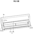
- FIGS. 10A to 10C are schematic diagrams illustrating modifications of the drain pan section of the housing 7.
- the housing 7A in an example illustrated FIG. 10A is different from the housing 7 illustrated in FIG. 3 in that: the rear drain pan 17R has a shape extended in the left-right direction; and the communicating passages 21a, 21b are arranged in places on a front side of the rear drain pan 17R.
- the communicating passages 21a, 21b are arranged in locations near both left and right sides of the rear drain pan 17R.
- the bottom surfaces of the communicating passages 21a, 21b are formed inclining downward from the rear drain pan 17R toward the front drain pan 17F.
- the housing 7B in an example illustrated FIG. 10B is different from the housing 7 illustrated in FIG. 3 in that: the communicating passage 21 is arranged only in a location on either of the left and right sides of the rear drain pan 17R. Furthermore, the bottom surface of the rear drain pan 17R is formed inclining downward from a side farthest from the communicating passage 21 toward a side nearest to the communicating passage 21.
- the housing 7C in an example illustrated FIG. 10C is different from the housing 7B illustrated in FIG. 10B in that: the rear drain pan 17R has a shape extended in the left-right direction; and the communicating part 21 is arranged in a location on a front side of the rear drain pan 17R.
- the communicating passage 21 may be arranged in locations near both the left and right sides of the rear drain pan 17R, in a location of either the left or right side of the rear drain pan 17R, or in a location near either the left or right side of the rear drain pan 17R, instead of being arranged on the two sides of the front drain pan 17F and the rear drain pan 17R.
- the communicating passage 21 thus can make the front drain pan 17F and the rear drain pan 17R communicate with each other.
- the bottom surface of the rear drain pan 17R is formed such that the bottom surface thereof is slightly lower on the sides nearest to the communicating passages 21a, 21b than on the sides farthest from the communicating passages 21a, 21b.
- the housings 7A, 7B, 7C like this illustrated in FIGS. 10A to 10C can increase freedom in the arrangement structure of the communicating passage 21, and can improve the efficiency of discharging the drain water which drops from the rear heat exchanger 16R into the rear drain pan 17R.
- the indoor unit 2 like this can efficiently take the drain water including the dust, which collects in the front drain pan 17F, into the drain pipe 22, and can discharge the drain water including the dust to the outside of the indoor unit 2 through the drain pipe 22.
- the indoor unit 2 can efficiently take the drain water including the dust into the drain pipe 22.
- the indoor unit 2 can excellently take the drain and the dust into the drain pipe 22, and send the drain water and the dust out to the outside of the indoor unit 2 through the drain pipe 22.
- the indoor unit 2 can inhibit the drain water and the dust from accumulating around the inlet 23 of the drain pipe 22.
- the indoor unit 2 accordingly can improve the efficiency of discharging the drain water which collects in the front drain pan 17F.
- the indoor unit 2 for the air conditioner 1 is capable of preventing the water from leaking to the outside of the indoor unit 2 during the freeze washing.
- the second embodiment provides an indoor unit 2A with the following points taken into consideration.
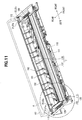
- FIG. 11 is a perspective diagram of a drain pan section in a housing 107 to be used for the indoor unit 2A.
- FIG. 12 is a partially-magnified diagram of the front drain pan 17F in the drain pan section.
- FIG. 12 is a magnified diagram illustrating the configuration of an A section and its vicinity in FIG. 11 .
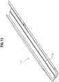
- FIG. 13 is a perspective diagram of the heat insulating material (foamed resin material) 111 to be used in the second embodiment.
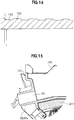
- FIGS. 14 and 15 are partially-magnified diagrams of a drainage part 120 in the front drain pan 17F.
- FIG. 11 is a perspective diagram of a drain pan section in a housing 107 to be used for the indoor unit 2A.
- FIG. 12 is a partially-magnified diagram of the front drain pan 17F in the drain pan section.
- FIG. 12 is a magnified diagram illustrating the configuration of an A section and its vicinity in FIG. 11 .
- FIG. 13 is a perspective diagram of the heat insulating material
- FIG. 14 illustrates a configuration of the drainage part 120 taken along the B-B line in the FIG. 12 .
- FIG. 15 illustrates a configuration of the drainage part 120 taken along the C-C line in the FIG. 12 , but near the inlet 23 of the drain pipe 22.
- FIG. 16 is a schematic diagram illustrating an arrangement relationship between the front heat exchanger 16F and the front drain pan 17F.
- the following points make the indoor unit 2A according to the second embodiment different from the indoor unit 2 (see FIG. 2 ) according to the first embodiment.
- the heat insulating material 111 (see FIGS. 11 and 12 ), the heat insulating material 161 (see FIG. 11 ) and the heat insulating material 211 (see FIG. 15 ) are members which are attached to the housing 107 of the indoor unit 2A to inhibit moisture in the air from condensing on various portions of the drain pan 17 due to cold drain water which flows into the drain pan 17 during the freeze washing.
- the indoor unit 2A can inhibit moisture in the air from condensing into condensation water to adhere to the drain pan 17, using the heat insulating materials 111, 161, 211 which are arranged on the respective portions of the drain pan 17.
- These heat insulating materials 111, 161, 211 are made of foamed resin material with low hygroscopicity, such as foamed styrol or foamed urethane.
- the heat insulating materials 111, 161 in which their respective flow passages in which drain water flows are formed are made of material with low hygroscopicity, and the surfaces of the heat insulating materials 111, 161 are water-repellent. Since the heat insulating materials 111, 161 like this absorb no water, they can inhibit the growth of molds. Furthermore, the heat insulating materials 111, 161 can make it easy to evaporate drain water flowing into the respective flow passage sections. The heat insulating materials 111, 161 can accordingly contribute to decreasing the size of the drain pan 17.
- mirror surface processing preferably may be applied to the flow passage sections in the heat insulating materials 111, 161 in order to facilitate the flow of the drain water.
- FIG. 13 illustrates an example of the heat insulating material 111.
- the heat insulating material 111 has a structure which enables the heat insulating material 111 to be attached to the drainage part 120 in the inside of the front drain pan 17F which extends in the front-rear direction of the front drain pan 17F.
- the projecting part 112 is formed on an upper surface of the heat insulating material 111.
- the projecting part 112 is formed extending in a direction in which the drain water flows (a direction in which the flow passage extends).
- the projecting part 112 functions as the uneven part 130 for decreasing the surface tension (boding force) of the drain water.
- the indoor unit 2A decreases the surface tension (boding force) of the drain water by use of the projecting part 112 on the heat insulating material 111, and can facilitate the flow of the drain water by allowing droplets of the drain water to flow as they are without having to wait until the droplets grow into drops through bonding. Thereby, the indoor unit 2A facilitates the flow of dust together with the drain water, and decreases an amount of dust which remains inside the drain pan 17.
- the heat insulating material 161 (see FIG. 11 ) has the same shape as the heat insulating material 111.
- the heat insulating material 161 has a structure which enables the heat insulating material 161 to be attached to the inside of the rear drain pan 17R.
- the projecting part 162 is formed extending in the direction in which the drain water flows (the direction in which the flow passage extends).
- the heat insulating material 211 (see FIG. 15 ) has a structure which enables the heat insulating material 211 to be attached to a space located near the inlet 23 of the drain pipe 22, and formed under the drainage part 120 in the front drain pan 17F.
- the projecting parts 122 are formed on the drainage part 120 in the front drain pan 17F (see FIGS. 11 and 12 ). Each projecting part 122 is formed extending in the direction in which the drain water flows (the direction in which the flow passage extends) . In this embodiment, the upper surface of the projecting part 122 is formed in the shape of a substantially flat surface (see FIG. 14 ) . Like the projecting part 112, the projecting parts 122 function as the uneven part 130 for decreasing the surface tension (boding force) of the drain water.
- the projecting parts 122 are formed on the drainage part 120 except for in a place immediately before the inlet 23 of the drain pipe 22 (see FIG. 12 ). Thereby, the indoor unit 2A inhibits accumulation of dust around the inlet 23 of the drain pipe 22.
- the projecting parts 122 have a configuration in which the projecting parts 122 are formed directly on the housing 107 which includes the front drain pan 17F.
- the indoor unit 2A may be designed such that: the projecting parts 122 are beforehand formed on a member (not illustrated) separate from the housing 107; and the projecting parts 122 are arranged on the drainage part 120 by attaching the separate member to the drainage part 120.
- a bottom surface of the drainage part 120 in the front drain pan 17F has a shape in which the bottom surface inclines downward toward the inlet 23 of the drain pipe 22 ( FIG. 12 ).
- the drainage part 120 in the front drain pan 17F has a shape in which a recessed portion is formed in the bottom surface near the outlet of the flow passage.
- the communicating passage 21 is provided with the projecting parts 172 (see FIG. 11 ).
- the projecting parts 172 are formed extending in the direction in which the drain water flows (the direction in which the flow passage extends).
- the projecting parts 172 have a configuration in which the projecting parts 172 are formed directly on the housing 107 which includes the front drain pan 17F.
- the heat exchanger 16 in the illustrated example, the front heat exchange 16F
- the drain pan 17 in the illustrated example, the front drain pan 17F
- the indoor unit 2A has a configuration in which the heat exchanger 16 (in the illustrated example, the front heat exchange 16F) and the drain pan 17 (in the illustrated example, the front drain pan 17F) are arranged in close contact with each other, that is to say, a configuration in which no gap is formed between the heat exchanger 16 and the drain pan 17.
- the indoor unit 2A like this can inhibit a decrease in the heat exchanging efficiency, and the occurrence of water droppings (leakage of water to the outside of the indoor unit 2A) which would occur if a gap were formed between the heat exchanger 16 and the drain pan 17.
- the indoor unit 2A can facilitate the movement of condensation water adhering to the fins 20 of the heat exchanger 16 from the fins 20 of the heat exchanger 16 to the drain pan 17. Thereby, the indoor unit 2A can improve the efficiency of washing down the dust which adheres to the heat exchanger 16.
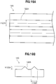
- FIG. 17 is a schematic diagram of a heat insulating material (foamed resin material) 111A according to a modification.
- FIG. 17A illustrates a shape of the heat insulating material 111A which is viewed from above.
- FIG. 17B illustrates a cross-sectional shape of the heat insulating material 111A.
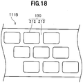
- FIG. 18 is a schematic diagram of a heat insulating material (foamed resin material) 111B according to another modification, and illustrates a shape of the heat insulating material 111B which is viewed from above.
- the heat insulating material 111A has a configuration in which: multiple substantially rectangular projecting parts 212 are arranged at equal intervals in the vertical and horizontal directions; and recessed parts 213 are formed between the projecting parts 212.
- each recessed part 213 is substantially shaped like a triangle which becomes wider upward.
- the recessed parts 213 are formed with a depth h213, with a width t213, and at equal intervals.
- the heat insulating material 111A like this decreases the surface tension (boding force) of the drain water by use of the projecting parts 212, and can facilitate the flow of the drain water by allowing droplets of the drain water to flow as they are without having to wait until the droplets grow into drops through bonding.
- the indoor unit 2A facilitates the flow of the dust together with the drain water, and can decrease an amount of dust which remains inside the drain pan 17.
- the heat insulating material 111A has a larger surface area than the heat insulating material 111 (see FIG. 13 ).
- the heat insulating material 111A makes it easier for drain water flowing into the flow passage section to evaporate than the heat insulating material 111 (see FIG. 13 ).
- the heat insulating material 111B in an example illustrated in FIG. 18 is different from the heat insulating material 111A (see FIG. 18 ) in that the heat insulating material 111B has a configuration in which the projecting parts 212 are staggered one after another. Like the heat insulating material 111A, the heat insulating material 111B decreases the surface tension (boding force) of the drain water by use of the projecting parts 212, and can facilitate the flow of the drain water. Furthermore, like the heat insulating material 111A, the heat insulating material 111B has a larger surface area than the heat insulating material 111 (see FIG. 13 ), since the projecting parts 212 are formed in the flow passage section. Thus, like the heat insulating material 111A, the heat insulating material 111B makes it easier for drain water flowing into the flow passage section to evaporate than the heat insulating material 111 (see FIG. 13 ).
- FIG. 19 is a schematic diagram of the drainage part 120 in the front drain pan 17F according to another modification.
- each projecting part 122A is substantially shaped like a triangle which becomes narrower upward.
- Each projecting part 122A is formed extending in the direction in which the drain water flows (the direction in which the flow passage extends) .
- Each projecting part 122A is formed with a depth h122A, and with a width t122A.
- the drainage part 120 like this decreases the surface tension (bonding force) of the drain water by use of the projecting parts 122A, and can facilitate the flow of the drain water.
- the indoor unit 2A according to the second embodiment is capable of preventing the water from leaking to the outside of the indoor unit 2A during the freeze washing, like the indoor unit 2 according to the first embodiment.
- the indoor unit 2A can improve the drainage efficiency since the indoor unit 2A can facilitate the flow of the drain water. Moreover, the indoor unit 2A can inhibit moisture in the air from condensing to adhere to the drain pan 17.
Landscapes
- Engineering & Computer Science (AREA)
- Chemical & Material Sciences (AREA)
- Combustion & Propulsion (AREA)
- Mechanical Engineering (AREA)
- General Engineering & Computer Science (AREA)
- Physics & Mathematics (AREA)
- Thermal Sciences (AREA)
- Devices For Blowing Cold Air, Devices For Blowing Warm Air, And Means For Preventing Water Condensation In Air Conditioning Units (AREA)
- Air Filters, Heat-Exchange Apparatuses, And Housings Of Air-Conditioning Units (AREA)
- Air Conditioning Control Device (AREA)
Applications Claiming Priority (2)
| Application Number | Priority Date | Filing Date | Title |
|---|---|---|---|
| JP2017089969A JP6340111B1 (ja) | 2017-04-28 | 2017-04-28 | 空気調和機の室内機 |
| PCT/JP2017/036039 WO2018198400A1 (ja) | 2017-04-28 | 2017-10-03 | 空気調和機の室内機 |
Publications (3)
| Publication Number | Publication Date |
|---|---|
| EP3438559A1 true EP3438559A1 (de) | 2019-02-06 |
| EP3438559A4 EP3438559A4 (de) | 2020-01-08 |
| EP3438559B1 EP3438559B1 (de) | 2023-11-29 |
Family
ID=62487529
Family Applications (1)
| Application Number | Title | Priority Date | Filing Date |
|---|---|---|---|
| EP17895510.0A Active EP3438559B1 (de) | 2017-04-28 | 2017-10-03 | Klimaanlageninnenraumeinheit |
Country Status (6)
| Country | Link |
|---|---|
| EP (1) | EP3438559B1 (de) |
| JP (1) | JP6340111B1 (de) |
| CN (1) | CN109154445B (de) |
| MY (1) | MY173637A (de) |
| TW (1) | TWI644063B (de) |
| WO (1) | WO2018198400A1 (de) |
Cited By (4)
| Publication number | Priority date | Publication date | Assignee | Title |
|---|---|---|---|---|
| FR3119011A1 (fr) * | 2021-01-18 | 2022-07-22 | Eurevia | Dispositif de renouvellement et de traitement d’air |
| EP4033165A1 (de) * | 2021-01-21 | 2022-07-27 | Panasonic Intellectual Property Management Co., Ltd. | Klimaanlage |
| DE102022110678A1 (de) | 2022-05-02 | 2023-11-02 | Stiebel Eltron Gmbh & Co. Kg | Lüftungsgerät |
| US12208661B2 (en) | 2020-01-31 | 2025-01-28 | Mitsubishi Heavy Industries Thermal Systems, Ltd. | Air conditioning device for vehicle |
Families Citing this family (12)
| Publication number | Priority date | Publication date | Assignee | Title |
|---|---|---|---|---|
| CN110873416B (zh) * | 2018-08-31 | 2021-07-23 | 重庆海尔空调器有限公司 | 一种空调及其自清洁的控制方法 |
| JP6685358B2 (ja) * | 2018-09-25 | 2020-04-22 | 日立ジョンソンコントロールズ空調株式会社 | 空気調和機の室内機 |
| CN109520113B (zh) * | 2018-12-14 | 2024-07-19 | 广东美的制冷设备有限公司 | 接水盘和具有其的空调器 |
| JP6614389B1 (ja) * | 2019-07-12 | 2019-12-04 | ダイキン工業株式会社 | 冷凍装置の室内機 |
| CN110500661B (zh) * | 2019-07-17 | 2021-07-02 | 山东华宇工学院 | 一种带有除尘提醒功能的变色空调室内机 |
| CN110470070B (zh) * | 2019-08-05 | 2021-02-02 | 南京天加环境科技有限公司 | 一种空调自清洁控制方法 |
| CN110986273A (zh) * | 2019-11-18 | 2020-04-10 | 珠海格力电器股份有限公司 | 一种换热器自清洁装置及空调 |
| CN114165913B (zh) * | 2020-09-10 | 2025-06-06 | 宁波奥克斯电气有限公司 | 一种空调器接水盘及空调器防凝露控制方法及装置 |
| CN112254307B (zh) * | 2020-10-22 | 2021-10-15 | 珠海格力电器股份有限公司 | 一种空调清洁控制方法、装置、设备和存储介质 |
| CN113106713A (zh) * | 2021-04-01 | 2021-07-13 | 江苏友奥电器有限公司 | 一种干衣机 |
| JP7685449B2 (ja) * | 2022-02-02 | 2025-05-29 | 株式会社コロナ | 空気調和機 |
| JP7587164B2 (ja) * | 2022-09-30 | 2024-11-20 | ダイキン工業株式会社 | 壁掛け式空調室内機 |
Family Cites Families (24)
| Publication number | Priority date | Publication date | Assignee | Title |
|---|---|---|---|---|
| JPS57132122U (de) * | 1981-02-10 | 1982-08-17 | ||
| JPS57184491U (de) * | 1981-05-16 | 1982-11-22 | ||
| JPH0419365Y2 (de) * | 1986-11-25 | 1992-05-01 | ||
| JPS63110830U (de) * | 1987-01-09 | 1988-07-16 | ||
| JPH05164344A (ja) * | 1991-12-12 | 1993-06-29 | Toshiba Corp | 空気調和機 |
| JPH06257778A (ja) * | 1993-03-01 | 1994-09-16 | Daikin Ind Ltd | 空気調和機のドレン構造 |
| JPH10176841A (ja) * | 1996-12-16 | 1998-06-30 | Hitachi Air Conditioning & Refrig Co Ltd | エレベータ用空調機 |
| JPH10259953A (ja) * | 1997-03-19 | 1998-09-29 | Fujitsu General Ltd | 空気調和機 |
| KR100256416B1 (ko) * | 1997-12-15 | 2000-05-15 | 윤종용 | 공기조화기의 상단 응축수 처리장치 |
| JP2001317760A (ja) * | 2000-05-09 | 2001-11-16 | Funai Electric Co Ltd | 空気調和機 |
| JP2002098347A (ja) * | 2000-09-22 | 2002-04-05 | Chofu Seisakusho Co Ltd | 空気調和機の室内機における排水構造 |
| JP2005098559A (ja) * | 2003-08-26 | 2005-04-14 | Toshiba Corp | 冷蔵庫 |
| WO2006098436A1 (ja) * | 2005-03-18 | 2006-09-21 | Toshiba Carrier Corporation | 空気調和装置の室内機 |
| JP2006300431A (ja) * | 2005-04-21 | 2006-11-02 | Mitsubishi Electric Corp | 空気調和機の室内機用ドレンパン、空気調和機の室内機およびその製造方法 |
| JP4931566B2 (ja) | 2006-11-30 | 2012-05-16 | 東芝キヤリア株式会社 | 空気調和機 |
| JP2008202829A (ja) * | 2007-02-19 | 2008-09-04 | Sharp Corp | ドレンパン及びこれを備えた空気調和機 |
| JP2010014288A (ja) * | 2008-07-01 | 2010-01-21 | Toshiba Carrier Corp | 空気調和機 |
| JP5405209B2 (ja) * | 2009-06-30 | 2014-02-05 | 三洋電機株式会社 | 空気調和装置 |
| JP5871665B2 (ja) * | 2012-03-05 | 2016-03-01 | 三菱電機株式会社 | 空気調和機の室内機 |
| CN104110727B (zh) * | 2013-07-30 | 2017-10-31 | 广东美的制冷设备有限公司 | 壁挂式空调器 |
| CN104848738B (zh) * | 2015-04-22 | 2019-03-19 | 珠海格力电器股份有限公司 | 空调室内换热器的清洁方法及装置 |
| CN104848420B (zh) * | 2015-04-30 | 2018-07-13 | 武汉海尔电器股份有限公司 | 一种壁挂式空调器 |
| WO2017049089A1 (en) * | 2015-09-16 | 2017-03-23 | Whirlpool Corporation | Condensate wicking medium on indoor unit fan scroll to distribute moisture for revaporization into dry air |
| CN105444265A (zh) * | 2015-12-07 | 2016-03-30 | 珠海格力电器股份有限公司 | 空调室内机 |
-
2017
- 2017-04-28 JP JP2017089969A patent/JP6340111B1/ja active Active
- 2017-10-03 CN CN201780011595.2A patent/CN109154445B/zh active Active
- 2017-10-03 WO PCT/JP2017/036039 patent/WO2018198400A1/ja not_active Ceased
- 2017-10-03 MY MYPI2018702856A patent/MY173637A/en unknown
- 2017-10-03 EP EP17895510.0A patent/EP3438559B1/de active Active
- 2017-11-15 TW TW106139435A patent/TWI644063B/zh active
Cited By (4)
| Publication number | Priority date | Publication date | Assignee | Title |
|---|---|---|---|---|
| US12208661B2 (en) | 2020-01-31 | 2025-01-28 | Mitsubishi Heavy Industries Thermal Systems, Ltd. | Air conditioning device for vehicle |
| FR3119011A1 (fr) * | 2021-01-18 | 2022-07-22 | Eurevia | Dispositif de renouvellement et de traitement d’air |
| EP4033165A1 (de) * | 2021-01-21 | 2022-07-27 | Panasonic Intellectual Property Management Co., Ltd. | Klimaanlage |
| DE102022110678A1 (de) | 2022-05-02 | 2023-11-02 | Stiebel Eltron Gmbh & Co. Kg | Lüftungsgerät |
Also Published As
| Publication number | Publication date |
|---|---|
| EP3438559A4 (de) | 2020-01-08 |
| TW201839330A (zh) | 2018-11-01 |
| CN109154445B (zh) | 2020-02-04 |
| MY173637A (en) | 2020-02-12 |
| TWI644063B (zh) | 2018-12-11 |
| JP6340111B1 (ja) | 2018-06-06 |
| EP3438559B1 (de) | 2023-11-29 |
| CN109154445A (zh) | 2019-01-04 |
| WO2018198400A1 (ja) | 2018-11-01 |
| JP2018189271A (ja) | 2018-11-29 |
Similar Documents
| Publication | Publication Date | Title |
|---|---|---|
| EP3438559B1 (de) | Klimaanlageninnenraumeinheit | |
| EP3617603B1 (de) | Klimaanlage | |
| CN107031491B (zh) | 冷却装置 | |
| CN108194995A (zh) | 一种空调 | |
| JP2668717B2 (ja) | 人工降雪装置 | |
| CN107869877A (zh) | 管道式风扇组件及使用该管道式风扇组件的冷却单元 | |
| JP2008196804A (ja) | 車輛の運転エネルギー省力化装置 | |
| JP6417073B1 (ja) | 空気調和機 | |
| CN208566965U (zh) | 一种包装车间降温系统 | |
| JPH10216436A (ja) | 集塵フィルタとその使用方法 | |
| JPH09263920A (ja) | 溶融メッキラインのスナウト内凝固亜鉛の鋼板付着防止方法 | |
| JPH0694263A (ja) | 多室型空気調和機 | |
| CN110402352A (zh) | 空调机 | |
| JP2010223507A (ja) | 除霜装置及びこれを備えるエアサイクル冷凍システム | |
| JP2004308937A (ja) | 外気取入れチャンバ | |
| JPS601023A (ja) | 車両用冷房装置 | |
| JPH09210406A (ja) | 局所冷房機のドレン水滴下装置 | |
| KR200474574Y1 (ko) | 열교환기 착상방지장치 | |
| JPS5839341Y2 (ja) | 空気調和機の室外ユニット | |
| JPS6213847Y2 (de) | ||
| JPH1194285A (ja) | 空気調和機 | |
| JP3024513U (ja) | クロスフロー式の密閉型ヒーティングタワー | |
| JPH074685A (ja) | 加湿冷風機 | |
| JPS5895137A (ja) | 分離形空気調和機の室内ユニツト | |
| JPH01169249A (ja) | 空気調和機の排水処理装置 |
Legal Events
| Date | Code | Title | Description |
|---|---|---|---|
| STAA | Information on the status of an ep patent application or granted ep patent |
Free format text: STATUS: UNKNOWN |
|
| STAA | Information on the status of an ep patent application or granted ep patent |
Free format text: STATUS: THE INTERNATIONAL PUBLICATION HAS BEEN MADE |
|
| PUAI | Public reference made under article 153(3) epc to a published international application that has entered the european phase |
Free format text: ORIGINAL CODE: 0009012 |
|
| STAA | Information on the status of an ep patent application or granted ep patent |
Free format text: STATUS: THE APPLICATION HAS BEEN PUBLISHED |
|
| AK | Designated contracting states |
Kind code of ref document: A1 Designated state(s): AL AT BE BG CH CY CZ DE DK EE ES FI FR GB GR HR HU IE IS IT LI LT LU LV MC MK MT NL NO PL PT RO RS SE SI SK SM TR |
|
| AX | Request for extension of the european patent |
Extension state: BA ME |
|
| STAA | Information on the status of an ep patent application or granted ep patent |
Free format text: STATUS: REQUEST FOR EXAMINATION WAS MADE |
|
| 17P | Request for examination filed |
Effective date: 20190502 |
|
| RBV | Designated contracting states (corrected) |
Designated state(s): AL AT BE BG CH CY CZ DE DK EE ES FI FR GB GR HR HU IE IS IT LI LT LU LV MC MK MT NL NO PL PT RO RS SE SI SK SM TR |
|
| A4 | Supplementary search report drawn up and despatched |
Effective date: 20191211 |
|
| RIC1 | Information provided on ipc code assigned before grant |
Ipc: F24F 13/22 20060101ALI20191205BHEP Ipc: F24F 1/00 20190101AFI20191205BHEP Ipc: F24F 1/0063 20190101ALI20191205BHEP |
|
| DAV | Request for validation of the european patent (deleted) | ||
| DAX | Request for extension of the european patent (deleted) | ||
| STAA | Information on the status of an ep patent application or granted ep patent |
Free format text: STATUS: EXAMINATION IS IN PROGRESS |
|
| 17Q | First examination report despatched |
Effective date: 20201007 |
|
| GRAP | Despatch of communication of intention to grant a patent |
Free format text: ORIGINAL CODE: EPIDOSNIGR1 |
|
| STAA | Information on the status of an ep patent application or granted ep patent |
Free format text: STATUS: GRANT OF PATENT IS INTENDED |
|
| INTG | Intention to grant announced |
Effective date: 20230424 |
|
| GRAS | Grant fee paid |
Free format text: ORIGINAL CODE: EPIDOSNIGR3 |
|
| GRAA | (expected) grant |
Free format text: ORIGINAL CODE: 0009210 |
|
| STAA | Information on the status of an ep patent application or granted ep patent |
Free format text: STATUS: THE PATENT HAS BEEN GRANTED |
|
| AK | Designated contracting states |
Kind code of ref document: B1 Designated state(s): AL AT BE BG CH CY CZ DE DK EE ES FI FR GB GR HR HU IE IS IT LI LT LU LV MC MK MT NL NO PL PT RO RS SE SI SK SM TR |
|
| REG | Reference to a national code |
Ref country code: GB Ref legal event code: FG4D |
|
| REG | Reference to a national code |
Ref country code: CH Ref legal event code: EP |
|
| REG | Reference to a national code |
Ref country code: DE Ref legal event code: R096 Ref document number: 602017077107 Country of ref document: DE |
|
| REG | Reference to a national code |
Ref country code: IE Ref legal event code: FG4D |
|
| REG | Reference to a national code |
Ref country code: LT Ref legal event code: MG9D |
|
| REG | Reference to a national code |
Ref country code: NL Ref legal event code: MP Effective date: 20231129 |
|
| PG25 | Lapsed in a contracting state [announced via postgrant information from national office to epo] |
Ref country code: GR Free format text: LAPSE BECAUSE OF FAILURE TO SUBMIT A TRANSLATION OF THE DESCRIPTION OR TO PAY THE FEE WITHIN THE PRESCRIBED TIME-LIMIT Effective date: 20240301 |
|
| PG25 | Lapsed in a contracting state [announced via postgrant information from national office to epo] |
Ref country code: IS Free format text: LAPSE BECAUSE OF FAILURE TO SUBMIT A TRANSLATION OF THE DESCRIPTION OR TO PAY THE FEE WITHIN THE PRESCRIBED TIME-LIMIT Effective date: 20240329 |
|
| PG25 | Lapsed in a contracting state [announced via postgrant information from national office to epo] |
Ref country code: LT Free format text: LAPSE BECAUSE OF FAILURE TO SUBMIT A TRANSLATION OF THE DESCRIPTION OR TO PAY THE FEE WITHIN THE PRESCRIBED TIME-LIMIT Effective date: 20231129 |
|
| PG25 | Lapsed in a contracting state [announced via postgrant information from national office to epo] |
Ref country code: ES Free format text: LAPSE BECAUSE OF FAILURE TO SUBMIT A TRANSLATION OF THE DESCRIPTION OR TO PAY THE FEE WITHIN THE PRESCRIBED TIME-LIMIT Effective date: 20231129 |
|
| PG25 | Lapsed in a contracting state [announced via postgrant information from national office to epo] |
Ref country code: LT Free format text: LAPSE BECAUSE OF FAILURE TO SUBMIT A TRANSLATION OF THE DESCRIPTION OR TO PAY THE FEE WITHIN THE PRESCRIBED TIME-LIMIT Effective date: 20231129 Ref country code: IS Free format text: LAPSE BECAUSE OF FAILURE TO SUBMIT A TRANSLATION OF THE DESCRIPTION OR TO PAY THE FEE WITHIN THE PRESCRIBED TIME-LIMIT Effective date: 20240329 Ref country code: GR Free format text: LAPSE BECAUSE OF FAILURE TO SUBMIT A TRANSLATION OF THE DESCRIPTION OR TO PAY THE FEE WITHIN THE PRESCRIBED TIME-LIMIT Effective date: 20240301 Ref country code: ES Free format text: LAPSE BECAUSE OF FAILURE TO SUBMIT A TRANSLATION OF THE DESCRIPTION OR TO PAY THE FEE WITHIN THE PRESCRIBED TIME-LIMIT Effective date: 20231129 Ref country code: BG Free format text: LAPSE BECAUSE OF FAILURE TO SUBMIT A TRANSLATION OF THE DESCRIPTION OR TO PAY THE FEE WITHIN THE PRESCRIBED TIME-LIMIT Effective date: 20240229 |
|
| REG | Reference to a national code |
Ref country code: AT Ref legal event code: MK05 Ref document number: 1636490 Country of ref document: AT Kind code of ref document: T Effective date: 20231129 |
|
| PG25 | Lapsed in a contracting state [announced via postgrant information from national office to epo] |
Ref country code: NL Free format text: LAPSE BECAUSE OF FAILURE TO SUBMIT A TRANSLATION OF THE DESCRIPTION OR TO PAY THE FEE WITHIN THE PRESCRIBED TIME-LIMIT Effective date: 20231129 |
|
| PG25 | Lapsed in a contracting state [announced via postgrant information from national office to epo] |
Ref country code: SE Free format text: LAPSE BECAUSE OF FAILURE TO SUBMIT A TRANSLATION OF THE DESCRIPTION OR TO PAY THE FEE WITHIN THE PRESCRIBED TIME-LIMIT Effective date: 20231129 Ref country code: RS Free format text: LAPSE BECAUSE OF FAILURE TO SUBMIT A TRANSLATION OF THE DESCRIPTION OR TO PAY THE FEE WITHIN THE PRESCRIBED TIME-LIMIT Effective date: 20231129 Ref country code: PL Free format text: LAPSE BECAUSE OF FAILURE TO SUBMIT A TRANSLATION OF THE DESCRIPTION OR TO PAY THE FEE WITHIN THE PRESCRIBED TIME-LIMIT Effective date: 20231129 Ref country code: NO Free format text: LAPSE BECAUSE OF FAILURE TO SUBMIT A TRANSLATION OF THE DESCRIPTION OR TO PAY THE FEE WITHIN THE PRESCRIBED TIME-LIMIT Effective date: 20240229 Ref country code: NL Free format text: LAPSE BECAUSE OF FAILURE TO SUBMIT A TRANSLATION OF THE DESCRIPTION OR TO PAY THE FEE WITHIN THE PRESCRIBED TIME-LIMIT Effective date: 20231129 Ref country code: LV Free format text: LAPSE BECAUSE OF FAILURE TO SUBMIT A TRANSLATION OF THE DESCRIPTION OR TO PAY THE FEE WITHIN THE PRESCRIBED TIME-LIMIT Effective date: 20231129 Ref country code: HR Free format text: LAPSE BECAUSE OF FAILURE TO SUBMIT A TRANSLATION OF THE DESCRIPTION OR TO PAY THE FEE WITHIN THE PRESCRIBED TIME-LIMIT Effective date: 20231129 |
|
| PG25 | Lapsed in a contracting state [announced via postgrant information from national office to epo] |
Ref country code: DK Free format text: LAPSE BECAUSE OF FAILURE TO SUBMIT A TRANSLATION OF THE DESCRIPTION OR TO PAY THE FEE WITHIN THE PRESCRIBED TIME-LIMIT Effective date: 20231129 |
|
| PG25 | Lapsed in a contracting state [announced via postgrant information from national office to epo] |
Ref country code: CZ Free format text: LAPSE BECAUSE OF FAILURE TO SUBMIT A TRANSLATION OF THE DESCRIPTION OR TO PAY THE FEE WITHIN THE PRESCRIBED TIME-LIMIT Effective date: 20231129 Ref country code: AT Free format text: LAPSE BECAUSE OF FAILURE TO SUBMIT A TRANSLATION OF THE DESCRIPTION OR TO PAY THE FEE WITHIN THE PRESCRIBED TIME-LIMIT Effective date: 20231129 |
|
| PG25 | Lapsed in a contracting state [announced via postgrant information from national office to epo] |
Ref country code: SK Free format text: LAPSE BECAUSE OF FAILURE TO SUBMIT A TRANSLATION OF THE DESCRIPTION OR TO PAY THE FEE WITHIN THE PRESCRIBED TIME-LIMIT Effective date: 20231129 |
|
| PG25 | Lapsed in a contracting state [announced via postgrant information from national office to epo] |
Ref country code: SM Free format text: LAPSE BECAUSE OF FAILURE TO SUBMIT A TRANSLATION OF THE DESCRIPTION OR TO PAY THE FEE WITHIN THE PRESCRIBED TIME-LIMIT Effective date: 20231129 Ref country code: SK Free format text: LAPSE BECAUSE OF FAILURE TO SUBMIT A TRANSLATION OF THE DESCRIPTION OR TO PAY THE FEE WITHIN THE PRESCRIBED TIME-LIMIT Effective date: 20231129 Ref country code: RO Free format text: LAPSE BECAUSE OF FAILURE TO SUBMIT A TRANSLATION OF THE DESCRIPTION OR TO PAY THE FEE WITHIN THE PRESCRIBED TIME-LIMIT Effective date: 20231129 Ref country code: IT Free format text: LAPSE BECAUSE OF FAILURE TO SUBMIT A TRANSLATION OF THE DESCRIPTION OR TO PAY THE FEE WITHIN THE PRESCRIBED TIME-LIMIT Effective date: 20231129 Ref country code: EE Free format text: LAPSE BECAUSE OF FAILURE TO SUBMIT A TRANSLATION OF THE DESCRIPTION OR TO PAY THE FEE WITHIN THE PRESCRIBED TIME-LIMIT Effective date: 20231129 Ref country code: DK Free format text: LAPSE BECAUSE OF FAILURE TO SUBMIT A TRANSLATION OF THE DESCRIPTION OR TO PAY THE FEE WITHIN THE PRESCRIBED TIME-LIMIT Effective date: 20231129 Ref country code: CZ Free format text: LAPSE BECAUSE OF FAILURE TO SUBMIT A TRANSLATION OF THE DESCRIPTION OR TO PAY THE FEE WITHIN THE PRESCRIBED TIME-LIMIT Effective date: 20231129 Ref country code: AT Free format text: LAPSE BECAUSE OF FAILURE TO SUBMIT A TRANSLATION OF THE DESCRIPTION OR TO PAY THE FEE WITHIN THE PRESCRIBED TIME-LIMIT Effective date: 20231129 |
|
| PG25 | Lapsed in a contracting state [announced via postgrant information from national office to epo] |
Ref country code: PT Free format text: LAPSE BECAUSE OF FAILURE TO SUBMIT A TRANSLATION OF THE DESCRIPTION OR TO PAY THE FEE WITHIN THE PRESCRIBED TIME-LIMIT Effective date: 20240401 |
|
| PG25 | Lapsed in a contracting state [announced via postgrant information from national office to epo] |
Ref country code: PT Free format text: LAPSE BECAUSE OF FAILURE TO SUBMIT A TRANSLATION OF THE DESCRIPTION OR TO PAY THE FEE WITHIN THE PRESCRIBED TIME-LIMIT Effective date: 20240401 |
|
| REG | Reference to a national code |
Ref country code: DE Ref legal event code: R097 Ref document number: 602017077107 Country of ref document: DE |
|
| PLBE | No opposition filed within time limit |
Free format text: ORIGINAL CODE: 0009261 |
|
| STAA | Information on the status of an ep patent application or granted ep patent |
Free format text: STATUS: NO OPPOSITION FILED WITHIN TIME LIMIT |
|
| PG25 | Lapsed in a contracting state [announced via postgrant information from national office to epo] |
Ref country code: SI Free format text: LAPSE BECAUSE OF FAILURE TO SUBMIT A TRANSLATION OF THE DESCRIPTION OR TO PAY THE FEE WITHIN THE PRESCRIBED TIME-LIMIT Effective date: 20231129 |
|
| PG25 | Lapsed in a contracting state [announced via postgrant information from national office to epo] |
Ref country code: SI Free format text: LAPSE BECAUSE OF FAILURE TO SUBMIT A TRANSLATION OF THE DESCRIPTION OR TO PAY THE FEE WITHIN THE PRESCRIBED TIME-LIMIT Effective date: 20231129 |
|
| 26N | No opposition filed |
Effective date: 20240830 |
|
| REG | Reference to a national code |
Ref country code: DE Ref legal event code: R119 Ref document number: 602017077107 Country of ref document: DE |
|
| REG | Reference to a national code |
Ref country code: CH Ref legal event code: PL |
|
| GBPC | Gb: european patent ceased through non-payment of renewal fee |
Effective date: 20241003 |
|
| PG25 | Lapsed in a contracting state [announced via postgrant information from national office to epo] |
Ref country code: MC Free format text: LAPSE BECAUSE OF FAILURE TO SUBMIT A TRANSLATION OF THE DESCRIPTION OR TO PAY THE FEE WITHIN THE PRESCRIBED TIME-LIMIT Effective date: 20231129 |
|
| PG25 | Lapsed in a contracting state [announced via postgrant information from national office to epo] |
Ref country code: DE Free format text: LAPSE BECAUSE OF NON-PAYMENT OF DUE FEES Effective date: 20250501 |
|
| PG25 | Lapsed in a contracting state [announced via postgrant information from national office to epo] |
Ref country code: GB Free format text: LAPSE BECAUSE OF NON-PAYMENT OF DUE FEES Effective date: 20241003 |
|
| PG25 | Lapsed in a contracting state [announced via postgrant information from national office to epo] |
Ref country code: LU Free format text: LAPSE BECAUSE OF NON-PAYMENT OF DUE FEES Effective date: 20241003 Ref country code: BE Free format text: LAPSE BECAUSE OF NON-PAYMENT OF DUE FEES Effective date: 20241031 |
|
| PG25 | Lapsed in a contracting state [announced via postgrant information from national office to epo] |
Ref country code: CH Free format text: LAPSE BECAUSE OF NON-PAYMENT OF DUE FEES Effective date: 20241031 |
|
| REG | Reference to a national code |
Ref country code: BE Ref legal event code: MM Effective date: 20241031 |
|
| PG25 | Lapsed in a contracting state [announced via postgrant information from national office to epo] |
Ref country code: FI Free format text: LAPSE BECAUSE OF FAILURE TO SUBMIT A TRANSLATION OF THE DESCRIPTION OR TO PAY THE FEE WITHIN THE PRESCRIBED TIME-LIMIT Effective date: 20231129 |
|
| PGFP | Annual fee paid to national office [announced via postgrant information from national office to epo] |
Ref country code: FR Payment date: 20250925 Year of fee payment: 9 |
|
| PG25 | Lapsed in a contracting state [announced via postgrant information from national office to epo] |
Ref country code: IE Free format text: LAPSE BECAUSE OF NON-PAYMENT OF DUE FEES Effective date: 20241003 |
|
| PG25 | Lapsed in a contracting state [announced via postgrant information from national office to epo] |
Ref country code: CY Free format text: LAPSE BECAUSE OF FAILURE TO SUBMIT A TRANSLATION OF THE DESCRIPTION OR TO PAY THE FEE WITHIN THE PRESCRIBED TIME-LIMIT; INVALID AB INITIO Effective date: 20171003 |
|
| PG25 | Lapsed in a contracting state [announced via postgrant information from national office to epo] |
Ref country code: HU Free format text: LAPSE BECAUSE OF FAILURE TO SUBMIT A TRANSLATION OF THE DESCRIPTION OR TO PAY THE FEE WITHIN THE PRESCRIBED TIME-LIMIT; INVALID AB INITIO Effective date: 20171003 |