EP3439976B1 - Enveloppe d'emballage, emballage et procédé de fabrication d'une enveloppe d'emballage - Google Patents
Enveloppe d'emballage, emballage et procédé de fabrication d'une enveloppe d'emballage Download PDFInfo
- Publication number
- EP3439976B1 EP3439976B1 EP17711150.7A EP17711150A EP3439976B1 EP 3439976 B1 EP3439976 B1 EP 3439976B1 EP 17711150 A EP17711150 A EP 17711150A EP 3439976 B1 EP3439976 B1 EP 3439976B1
- Authority
- EP
- European Patent Office
- Prior art keywords
- package
- fold lines
- packaging
- package sleeve
- gable
- Prior art date
- Legal status (The legal status is an assumption and is not a legal conclusion. Google has not performed a legal analysis and makes no representation as to the accuracy of the status listed.)
- Active
Links
Images


Classifications
-
- B—PERFORMING OPERATIONS; TRANSPORTING
- B65—CONVEYING; PACKING; STORING; HANDLING THIN OR FILAMENTARY MATERIAL
- B65D—CONTAINERS FOR STORAGE OR TRANSPORT OF ARTICLES OR MATERIALS, e.g. BAGS, BARRELS, BOTTLES, BOXES, CANS, CARTONS, CRATES, DRUMS, JARS, TANKS, HOPPERS, FORWARDING CONTAINERS; ACCESSORIES, CLOSURES, OR FITTINGS THEREFOR; PACKAGING ELEMENTS; PACKAGES
- B65D5/00—Rigid or semi-rigid containers of polygonal cross-section, e.g. boxes, cartons or trays, formed by folding or erecting one or more blanks made of paper
- B65D5/02—Rigid or semi-rigid containers of polygonal cross-section, e.g. boxes, cartons or trays, formed by folding or erecting one or more blanks made of paper by folding or erecting a single blank to form a tubular body with or without subsequent folding operations, or the addition of separate elements, to close the ends of the body
- B65D5/0209—Rigid or semi-rigid containers of polygonal cross-section, e.g. boxes, cartons or trays, formed by folding or erecting one or more blanks made of paper by folding or erecting a single blank to form a tubular body with or without subsequent folding operations, or the addition of separate elements, to close the ends of the body the tubular body having a curved or partially curved cross-section
-
- B—PERFORMING OPERATIONS; TRANSPORTING
- B65—CONVEYING; PACKING; STORING; HANDLING THIN OR FILAMENTARY MATERIAL
- B65D—CONTAINERS FOR STORAGE OR TRANSPORT OF ARTICLES OR MATERIALS, e.g. BAGS, BARRELS, BOTTLES, BOXES, CANS, CARTONS, CRATES, DRUMS, JARS, TANKS, HOPPERS, FORWARDING CONTAINERS; ACCESSORIES, CLOSURES, OR FITTINGS THEREFOR; PACKAGING ELEMENTS; PACKAGES
- B65D5/00—Rigid or semi-rigid containers of polygonal cross-section, e.g. boxes, cartons or trays, formed by folding or erecting one or more blanks made of paper
- B65D5/02—Rigid or semi-rigid containers of polygonal cross-section, e.g. boxes, cartons or trays, formed by folding or erecting one or more blanks made of paper by folding or erecting a single blank to form a tubular body with or without subsequent folding operations, or the addition of separate elements, to close the ends of the body
- B65D5/06—Rigid or semi-rigid containers of polygonal cross-section, e.g. boxes, cartons or trays, formed by folding or erecting one or more blanks made of paper by folding or erecting a single blank to form a tubular body with or without subsequent folding operations, or the addition of separate elements, to close the ends of the body with end-closing or contents-supporting elements formed by folding inwardly a wall extending from, and continuously around, an end of the tubular body
- B65D5/064—Rectangular containers having a body with gusset-flaps folded outwardly or adhered to the side or the top of the container
-
- B—PERFORMING OPERATIONS; TRANSPORTING
- B65—CONVEYING; PACKING; STORING; HANDLING THIN OR FILAMENTARY MATERIAL
- B65D—CONTAINERS FOR STORAGE OR TRANSPORT OF ARTICLES OR MATERIALS, e.g. BAGS, BARRELS, BOTTLES, BOXES, CANS, CARTONS, CRATES, DRUMS, JARS, TANKS, HOPPERS, FORWARDING CONTAINERS; ACCESSORIES, CLOSURES, OR FITTINGS THEREFOR; PACKAGING ELEMENTS; PACKAGES
- B65D5/00—Rigid or semi-rigid containers of polygonal cross-section, e.g. boxes, cartons or trays, formed by folding or erecting one or more blanks made of paper
- B65D5/02—Rigid or semi-rigid containers of polygonal cross-section, e.g. boxes, cartons or trays, formed by folding or erecting one or more blanks made of paper by folding or erecting a single blank to form a tubular body with or without subsequent folding operations, or the addition of separate elements, to close the ends of the body
- B65D5/029—Rigid or semi-rigid containers of polygonal cross-section, e.g. boxes, cartons or trays, formed by folding or erecting one or more blanks made of paper by folding or erecting a single blank to form a tubular body with or without subsequent folding operations, or the addition of separate elements, to close the ends of the body the tubular body presenting a special shape
-
- B—PERFORMING OPERATIONS; TRANSPORTING
- B65—CONVEYING; PACKING; STORING; HANDLING THIN OR FILAMENTARY MATERIAL
- B65D—CONTAINERS FOR STORAGE OR TRANSPORT OF ARTICLES OR MATERIALS, e.g. BAGS, BARRELS, BOTTLES, BOXES, CANS, CARTONS, CRATES, DRUMS, JARS, TANKS, HOPPERS, FORWARDING CONTAINERS; ACCESSORIES, CLOSURES, OR FITTINGS THEREFOR; PACKAGING ELEMENTS; PACKAGES
- B65D5/00—Rigid or semi-rigid containers of polygonal cross-section, e.g. boxes, cartons or trays, formed by folding or erecting one or more blanks made of paper
- B65D5/42—Details of containers or of foldable or erectable container blanks
- B65D5/4266—Folding lines, score lines, crease lines
-
- B—PERFORMING OPERATIONS; TRANSPORTING
- B32—LAYERED PRODUCTS
- B32B—LAYERED PRODUCTS, i.e. PRODUCTS BUILT-UP OF STRATA OF FLAT OR NON-FLAT, e.g. CELLULAR OR HONEYCOMB, FORM
- B32B2439/00—Containers; Receptacles
- B32B2439/40—Closed containers
- B32B2439/62—Boxes, cartons, cases
-
- B—PERFORMING OPERATIONS; TRANSPORTING
- B32—LAYERED PRODUCTS
- B32B—LAYERED PRODUCTS, i.e. PRODUCTS BUILT-UP OF STRATA OF FLAT OR NON-FLAT, e.g. CELLULAR OR HONEYCOMB, FORM
- B32B2439/00—Containers; Receptacles
- B32B2439/70—Food packaging
-
- B—PERFORMING OPERATIONS; TRANSPORTING
- B65—CONVEYING; PACKING; STORING; HANDLING THIN OR FILAMENTARY MATERIAL
- B65D—CONTAINERS FOR STORAGE OR TRANSPORT OF ARTICLES OR MATERIALS, e.g. BAGS, BARRELS, BOTTLES, BOXES, CANS, CARTONS, CRATES, DRUMS, JARS, TANKS, HOPPERS, FORWARDING CONTAINERS; ACCESSORIES, CLOSURES, OR FITTINGS THEREFOR; PACKAGING ELEMENTS; PACKAGES
- B65D5/00—Rigid or semi-rigid containers of polygonal cross-section, e.g. boxes, cartons or trays, formed by folding or erecting one or more blanks made of paper
- B65D5/42—Details of containers or of foldable or erectable container blanks
- B65D5/72—Contents-dispensing means
- B65D5/74—Spouts
- B65D5/746—Spouts formed separately from the container
Definitions
- the invention relates to a package jacket made of a composite material for the production of a package, comprising: a front surface, a rear surface, two side surfaces, bottom surfaces and gable surfaces, which are arranged on opposite sides of the two side surfaces, the front surface and the rear surface, and a Longitudinal seam that connects two edges of the composite material to form a circumferential pack jacket, the pack jacket having several fold lines, the two side surfaces each having a dummy fold line running through the side surface, the package jacket being folded exclusively along both dummy fold lines and the pack jacket both in the area the floor surfaces as well as in the area of the gable surfaces is open.
- the invention also relates to a packaging made of a composite material, the packaging being folded along the fold lines, the packaging being closed in the area of the bottom surface and in the area of the gable surface, and with the partial areas of both side walls adjoining the dummy fold lines each in an angular range between 160 ° and 200 °, in particular between 170 ° and 190 °, are arranged to one another.
- the invention finally relates to a method for producing a package from a package jacket made of a composite material.
- Packaging can be produced in different ways and from a wide variety of materials.
- a widespread possibility of their production consists in producing a blank from the packaging material, from which, by folding and further steps, first a package jacket and finally a package is created.
- This type of production has the advantage, among other things, that the blanks and pack sleeves are very flat and are therefore stacked to save space can be. In this way, the blanks or packaging jackets can be produced at a different location than the folding and filling of the packaging jackets.
- Composite materials are often used as the material, for example a composite composed of several thin layers of paper, cardboard, plastic or metal, in particular aluminum. Such packaging is particularly widespread in the food industry.
- a first manufacturing step often consists in producing a circumferential packaging jacket from a blank by folding and welding or gluing a seam.
- the blank is usually folded along embossed fold lines.
- the position of the fold lines corresponds to the position of the edges of the packaging to be produced from the pack jacket.
- a pack jacket is made from the sheet or sheet-like composite and finished ready for sale, whereby a pack jacket is to be regarded as ready for sale if, after removal from an outer packaging intended for transport from the production site to the place of use, it is readily available for processing in a intended filling machine is ready. In particular, this means that no mechanical interventions are required on the pack jacket to ensure smooth processing of the pack jacket on the filling machine provided for this purpose.
- Conditioning to the ambient climate and / or (additional) sterilization eg edge sterilization method by the applicant, on the other hand, can optionally also be carried out on a finished pack jacket during or after transport to the intended place of use.
- One method of making a package from a package jacket is for example from the WO 2015/003852 A9 known (there in particular Figures 1A to 1E ).
- the packaging described there has a rectangular cross-sectional area and is overall cuboid.
- packagings with cross-sectional areas that have more than four corners are also known. From the EP 0 936 150 B1 or the U.S. 6,042,527 for example, packaging with an octagonal cross-sectional area is known. The shape of the packaging is achieved by providing additional fold lines in the blanks.
- a disadvantage of folding the package jackets described along the later packaging edges is that only packages with angular cross-sectional areas can be produced.
- only packaging can be produced whose cross-sectional area in the vertical direction of the packaging is identical.
- alternative designs such as curves or free forms instead of the edges are not possible.
- Packing sleeves (“sleeves”) and packaging (“containers”) made therefrom are also from the EP 0 027 350 A1 known. With the package jacket described there, packagings can be produced whose cross-sectional area changes in the vertical direction (square cross-sectional areas on the gable and on the bottom, octagonal cross-sectional areas in between). However, this packaging also has only angular cross-sectional areas. Alternative designs such as curves or free forms instead of the edges are also used in the EP 0 027 350 A1 not described.
- the package jacket described there is also not made of composite material, but of cardboard or corrugated cardboard. An inner bag made of plastic is proposed for filling with liquids, so that the package jacket itself does not have to be suitable for producing liquid-tight packaging.
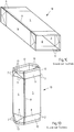
- Packing jackets and packaging made from them are also used in the GB 808,223 A described.
- a long cardboard material web is first provided with fold lines and then coated with a plastic layer (FIG. 6).
- a longitudinal seam has been produced (FIG. 7)
- the material web is unfolded into a tube with a rectangular cross section (FIG. 8).
- the two side surfaces of the tube are then folded inwards, whereby the tube assumes a flat shape (FIG. 9).
- transverse seams are created along which the tube can be folded and thus forms a stack (FIG. 10).
- By separating the tube in the area of the transverse seams individual packing jackets are obtained which are already closed on one side - by the transverse seam.
- a disadvantage of this procedure is that the pack jackets are already folded along six fold lines when they are separated from the tube, four of which fold lines form the edges of the later pack. These pack jackets are therefore also only suitable for producing packs with rectangular cross-sectional areas.
- the design freedom of the gable or floor surface that is created in the area of the already closed transverse seam is severely restricted.
- Particularly disadvantageous are the high deformation forces that are required to unfold and deform the pack jacket ("sleeve") into a pack open on one side (this intermediate state is also referred to as a "cup").
- the high deformation forces lead to a considerable load on the seams that have already been sealed, so that liquid and / or gas tightness is no longer given with sufficient reliability.
- the invention is based on the object of designing the pack jacket described at the outset and explained in more detail above in such a way that the production of packs - in particular liquid-tight packs - with complex geometry is made possible.
- the package jacket according to the invention consists of a composite material and is used to produce a package.
- the pack jacket can consist of a composite of several thin layers of paper, cardboard, plastic or metal, in particular aluminum.
- the packing jacket is preferably in one piece.
- the package shell comprises a front surface, a rear surface, two side surfaces and bottom surfaces and gable surfaces which are arranged on opposite sides of the two side surfaces, the front surface and the rear surface.
- the gable surfaces are preferably - in the case of a standing package - above the arranged on both side surfaces, the front surface and the rear surface, and the bottom surfaces are arranged below the two side surfaces, the front surface and the rear surface.
- the designation of the areas is based on the areas of the packaging to be produced from the pack jacket.
- the packing jacket furthermore comprises a longitudinal seam which connects two edges of the composite material to form a circumferential packing jacket.
- the longitudinal seam allows a flat - usually rectangular - blank to be produced into a circumferentially closed, circumferential packing jacket.
- the longitudinal seam can be produced, for example, by gluing and / or welding. Due to the longitudinal seam, such packaging jackets are also referred to as longitudinally-sealed packaging jackets.
- the package jacket also has several fold lines. Fold lines are intended to facilitate the folding of the package jacket and divide the package jacket into several areas. Fold lines can be created by weakening the material. Since the packaging should be impervious to liquids, no perforations are used as material weaknesses, but so-called "grooves". Creases are linear material displacements that are embossed into the composite material with spinning tools.
- the two side surfaces each have a dummy fold line running through the side surface, and that the package jacket is folded exclusively along both dummy fold lines.
- This design is based on the idea of not folding the package jacket along fold lines which form the edges of the packaging made from the package jacket.
- the package jacket should therefore not be folded at the fold lines which delimit the front surface, the rear surface and the two side surfaces from one another. Instead, the package jacket should only be folded along additionally provided fold lines ("dummy fold lines”), which later do not form an edge of the packaging, but are arranged between the edges of the packaging (here: in the side surfaces). Folding along the dummy fold lines therefore only takes place in the case of the package jacket, but not in the case of the packaging made from it.
- This allows a free design of the packaging geometry and in particular allows the Production of packaging with packaging cross-sections that are at least partially non-angular in the vertical direction.
- the packing jacket is open both in the area of the bottom surfaces and in the area of the gable surfaces.
- the package jacket has two openings, one opening being arranged in the region of the bottom surface and the other opening being arranged in the region of the gable surface.
- the package jacket can be unfolded particularly easily through the two opposing openings, which creates the shape of a tube or a sleeve.
- One advantage of packing sleeves that are open on both sides is - in contrast to the WO 97/32787 A2 - in the variable design options for the floor.
- the orientation of the "ears" can be freely selected.
- a floor variant can, for example, provide that the ears are folded under the rectangular surfaces of the floor and fastened there.
- Another floor variant can provide inwardly directed ears which are arranged above the rectangular surfaces of the floor that are later folded in.
- Another advantage of packaging jackets that are open on both sides is that their inner surfaces can be more easily sterilized, since a sterilizing medium, such as a gas mixture containing H 2 O 2, can simply be conveyed in a preferably laminar flow through the packaging jacket, which is open on both sides, to reduce germs.
- At least one of the fold lines runs unevenly, at least in sections, and in particular is curved or kinked.
- This design can in particular relate to those fold lines which connect the bottom surfaces to the gable surfaces, that is to say which run through the front surface, the rear surface or the side surfaces of the package jacket. It can be provided that at least one of the fold lines is continuously uneven and in particular is continuously curved. It can also be provided that not only one fold line, but all of the fold lines that connect the bottom surfaces with the gable surfaces, run at least in sections in an uneven manner and in particular are curved or kinked.
- the fold lines do not intersect, but rather maintain a minimum distance in the range between 0.1 mm and 2.0 mm from one another.
- the fold lines should approach each other, but not form any real intersections.
- the cutting of two folding lines that converge can be prevented, for example, in that at least one of these folding lines is interrupted in the area of the actual point of intersection.
- This design is based on the idea that intersecting fold lines represent a particularly high load on the package jacket, which can lead to damage to the package jacket when it is folded. This in turn can lead to leaking packaging. By maintaining a "safety margin" between fold lines, these stresses can be reduced.
- the bottom surfaces have corner points of the packaging and that the gable surfaces have corner points of the packaging and that no continuous straight fold line is provided between at least one corner point of the bottom surfaces and the corner point of the gable surfaces assigned to it.
- the designation of the corner points is based on the corner points of the packaging to be produced from the pack jacket.
- the corner points can, for example, lie on the fold line between a bottom surface or gable surface and the "jacket surface" adjoining it (that is, the front surface, the rear surface or a side surface).
- the corner points can also lie on the fold line between a triangular area and a rectangular area of a floor area or gable area.
- Each corner point of a floor area is assigned a corresponding corner point of a gable surface, which is the corner point that is arranged above this corner point when the packaging is standing.
- a corner axis runs through two mutually assigned corner points, which would correspond to a vertical packaging edge in the case of conventional cuboid packaging.
- no continuous straight fold line should be arranged between at least one pair of mutually assigned corner points - that is, on at least one corner axis.
- no continuous straight fold lines are arranged.
- the pack jacket is folded flat along both dummy fold lines by an angle of approximately 180 ° in each case.
- the folding at an angle of about 180 ° enables particularly flat pack sleeves.
- This allows packing sleeves to be stacked in a space-saving manner, which, for example, facilitates transport.
- the packaging jackets can be produced at a different location than the filling and production of the packaging takes place.
- the package jacket is preferably folded outwards along both dummy fold lines. As a result, the packaging jackets can be stacked particularly close to one another.
- Another embodiment of the package jacket provides that the two dummy fold lines run parallel to one another.
- the two dummy fold lines are preferably straight and run parallel to one another.
- the parallel arrangement has the advantage that the dummy fold lines can be impressed particularly easily in the composite material.
- the two side surfaces, the front surface and the rear surface are delimited by fold lines.
- the areas mentioned can be delimited by fold lines at the top (adjacent to the gable surface) and / or at the bottom (adjacent to the bottom surface).
- a lateral delimitation of the areas mentioned by fold lines can also be provided.
- Another embodiment of the packaging jacket is characterized by at least one free-form surface which is arranged between two adjacent surfaces from the group of the two side surfaces, the front surface and the rear surface.
- a freeform surface is understood to be a surface with a complex geometry. In particular, these are surfaces that are not exclusively in one plane, but are curved.
- the free-form surface can only cover part of the boundary between two adjacent surfaces from the group of the two side surfaces, the front surface and the rear surface, or it can completely separate the adjacent surfaces from one another.
- the at least one free-form surface is delimited by fold lines.
- the freeform surface can be delimited by fold lines at the top (adjacent to the gable surface) and / or at the bottom (adjacent to the bottom surface).
- a lateral delimitation of the free-form surface by fold lines can also be provided.
- the gable surface adjacent to the rear surface has a shorter length than the length of the gable surface adjacent to the front surface.
- This design means that the front surface of the packaging has a lower height than the rear surface of the packaging.
- the packaging thus has a sloping top. This can improve the pouring behavior of the packaging.
- an area in the area of the top of the packaging can be made relatively large and thus offers space for attaching an opening aid ("cap").
- the bottom surfaces and the gable surfaces each include two rectangular surfaces and six triangular surfaces.
- the rectangular areas and the triangular areas are preferably also surrounded or delimited by fold lines.
- the rectangular areas are used to fold the bottom and the gable of the packaging.
- the triangular areas serve to To fold the excess composite material into protruding "ears" which are then attached to the packaging.
- the dummy fold lines run through the point of contact between three adjacent triangular surfaces of the bottom surface and through the point of contact between three adjacent triangular surfaces of the gable surfaces.
- This arrangement of the dummy fold lines has the advantage that the dummy fold lines run through the bottom surface and the gable surface at a point where these surfaces have to be folded anyway, for example to form "ears". The folding of the package jacket along the dummy fold lines therefore already leads to a “pre-fold” of the fold line running centrally through the “ears”.
- Another advantage of the central arrangement of the bill fold lines in the side surfaces is that the bill fold lines limit the space for the design of the edges of the packaging as little as possible.
- two of the triangular surfaces of the bottom surface and / or the gable surface have approximately the same surface area.
- all three triangular surfaces of the bottom surface and / or the gable surface have different surface areas.
- Another embodiment of the package jacket provides that the fold lines and / or the dummy fold lines are embossed from the inside to the outside of the package jacket and / or from the outside to the inside of the package jacket.
- changing the embossing direction can lead to better folding results.
- outwardly directed and protruding lines can be generated in this way simultaneously or in one production step with the folding lines - not intended for folding - which, for example, serve to be able to grip the packaging better and hold it more securely.
- a combination of both embossing directions can be provided for a pack jacket.
- the composite material of the packing jacket have a thickness in the range between 150 g / m 2 and 400 g / m 2 , in particular between 200 g / m 2 and 250 g / m 2 .
- a strength in This range has proven to be a good compromise between low costs and low weight (the thinnest possible composite material) and adequate mechanical properties (the thickest possible composite material).
- the longitudinal seam connects two partial areas of the rear surface with one another.
- the longitudinal seam should therefore be arranged in the rear surface and divide it into two sub-areas. This has the advantage that the front surface - to which the customer pays the most attention - can be made seamless.
- Another advantage of the arrangement of the longitudinal seam in the rear surface is that the dummy fold lines arranged in the side surfaces do not collide with the longitudinal seam.
- the two partial areas of the rear surface can be of the same width (central longitudinal seam) or different widths (laterally offset longitudinal seam).
- the composite material has at least one layer of paper or cardboard which is covered at the edge of the longitudinal seam running inside the pack jacket.
- the purpose of covering the paper layer or cardboard layer is to avoid contact between the contents of the packaging and this layer. This serves on the one hand to prevent liquid from escaping through the - not liquid-tight - paper or cardboard layer and, on the other hand, to protect the contents of the packaging from contamination through the paper or cardboard layer (e.g. fibers of the cellulose).
- the layer made of paper or cardboard is covered by a sealing strip and / or by folding over the composite material in the area of the longitudinal seam.
- a sealing strip can for example be made of the same material as the innermost layer of the composite material and can be glued or welded to this bearing.
- Another possibility of covering is to fold over the composite material in the area of the longitudinal seam or to fold down. In this way, not all layers, but only the innermost layer of the composite material appear on the edge of the longitudinal seam running inside the package jacket. However, the innermost layer must anyway be made of a material that is suitable for contact with the contents of the packaging.
- the composite material is peeled in the area of the longitudinal seam.
- a “peeled” composite material is understood to mean a composite material which has fewer layers in the peeled area than in the other areas. The peeling has the advantage of a less pronounced increase in thickness, particularly in the area of overlapping of several material layers. The use of peeled composite material is therefore particularly advantageous when the composite material is folded over or folded over - for example in the area of the longitudinal seam.
- the package jacket can be supplemented by a material weakening, in particular an over-coated hole, in one of the gable surfaces for fastening a pouring element.
- the weakening of the material serves to facilitate the subsequent attachment of a pouring element.
- a through hole is first punched in the composite material, which is then coated over.
- the overcoating can take place, for example, with a plastic film and is used to seal the packaging until the pouring element is applied.
- the above-described object is also achieved by a packaging made of a composite material, the packaging being folded along the fold lines, the packaging being closed in the area of the bottom surface and in the area of the gable surface, and the partial areas of both side walls adjoining the dummy fold lines in each case in an angular range between 160 ° and 200 °, in particular between 170 ° and 190 ° to each other.
- the packaging is characterized in that it is made from a packaging casing according to one of Claims 1 to 19.
- the packaging is made from one of the packaging sleeves described above, many properties and advantages of the packaging sleeve also occur in the packaging.
- a particular advantage is that the packaging does not have any angular edges in the area of its lateral surface on its sides, although it was produced from a packaging casing which is folded at two points and thus has two folding edges.
- the packaging does not have a continuously straight folding edge along at least one vertical corner axis; very preferably, the packaging has no continuously straight folded edges on several or all of the vertical corner axes. This is achieved in that the package jacket is "folded back" along the two dummy fold lines during the production of the package, so that the partial areas of both side walls adjoining the dummy fold lines are each arranged approximately in the same plane.
- the dummy fold lines do not form the edges of the packaging, but lie - barely visible - in two almost flat outer surfaces of the packaging, namely in the two side surfaces.
- the packaging preferably has a volume in the range between 50 ml and 4000 ml, in particular between 80 ml and 1000 ml, very particularly between 200 ml and 350 ml.
- the packaging is preferably in one piece.
- the part of the packaging made from the composite material is preferably in one piece.
- This part of the packaging can be supplemented with further elements, for example a pouring element (e.g. a flap or screw cap made of plastic) or a drinking aid (e.g. a straw).
- a pouring element e.g. a flap or screw cap made of plastic
- a drinking aid e.g. a straw.
- the front surface and the rear surface are arranged approximately in planes lying parallel to one another.
- the two side surfaces are arranged approximately in planes lying parallel to one another.
- the packaging is characterized by ears that are placed against the bottom surfaces in the lower area of the packaging.
- the packaging is characterized by ears that are placed on the side surfaces in the upper area of the packaging.
- the ears can be placed on the floor surface in different ways:
- a floor variant provides that the ears are folded under the rectangular surfaces of the floor and fastened there.
- Another floor variant provides inwardly directed ears which are arranged above the rectangular surfaces of the floor that are later folded in.
- the first variant has the advantage that the ears are pressed securely against the packaging by the weight of the filled packaging, while the second variant, on the other hand, offers a particularly smooth bottom surface.
- the packaging can be gripped safely without touching the ears.
- the arrangement of the upper ears on the side surfaces has the advantage that a pouring element can be arranged on the top of the packaging.
- the object described at the beginning is also achieved by a method for producing a package from a package jacket made of a composite material.
- the method comprises the following steps: a) providing a packing jacket according to one of claims 1 to 19, b) unfolding the packing jacket along the fold lines between the side surfaces, the front surface and the rear surface, c) folding back the two side surfaces of the packing jacket along both dummy fold lines, and d) sealing the packaging jacket in the area of the bottom surfaces.
- step d) is carried out both after step b) and after step c).
- the process can be supplemented by the following step: e) Formation of free-form surfaces by deforming the composite material. Step e) can take place before the packaging is filled and / or after the packaging has been filled and closed.
- the method is also based on the idea of producing a package from a package jacket, the folded edges of which do not form any edges of the package produced from it.
- This is made possible by the fact that the package jacket, which has been folded along the dummy fold lines, is "folded back", the folding along the dummy fold lines being reversed.
- the dummy fold lines provided in the package jacket therefore do not form an edge of the package; Instead, they are arranged between the edges of the packaging (here: in the side surfaces).
- the package jacket is of course folded in the area of other fold lines which, however, do not necessarily have to be reshaped into angular fold edges and whose course can also be curved. This allows packaging with complex geometry to be produced. In that the packing casing is only closed in the area of the bottom surfaces after the casing has been unfolded and folded back, different bottom designs can also be achieved.
- steps b) and c) are carried out simultaneously. Steps b) and c) can only be carried out in phases or also continuously at the same time.
- a simultaneous execution of "unfolding" and “folding back” has the advantage that both folding processes can be carried out in the same system and possibly by the same tool. This can take place, for example, in that the two folding edges of the pack jackets formed by the dummy fold lines are moved towards one another, the pack jacket opening.
- the folding along the vertically running fold lines between the side surfaces, the front surface and the rear surface can be ensured by opening the package jacket in a - preferably multi-part - form, the inner contour of which corresponds to the outer contour of the packaging ("compression molding") ).
- the partial areas adjoining the dummy fold lines follow a side wall of the packaging the folding back again lie in an angular range between 160 ° and 200 °, in particular between 170 ° and 190 ° to each other.
- the side surfaces should therefore be folded back along the dummy fold lines so far that the side surfaces form almost flat side walls.
- FIG. 1A a blank 1 known from the prior art is shown, from which a package jacket can be formed.
- the blank 1 can comprise several layers of different materials, for example paper, cardboard, plastic or metal, in particular aluminum.
- the blank 1 has several fold lines 2, which are intended to facilitate the folding of the blank 1 and divide the blank 1 into several areas.
- the blank 1 can be divided into a first side surface 3, a second side surface 4, a front surface 5, a rear surface 6, a sealing surface 7, bottom surfaces 8 and gable surfaces 9.
- a pack jacket can be formed from the blank 1 by folding the blank 1 in such a way that the sealing surface 7 can be connected to the front surface 5, in particular by welding.
- Figure 1B shows a package jacket 10 known from the prior art in the folded flat state.
- the ones already related to Figure 1A described areas of the packing jacket are in Figure 1B provided with corresponding reference symbols.
- the packing jacket 10 is from the in Figure 1A shown blank 1 formed.
- the blank 1 was folded in such a way that the sealing surface 7 and the front surface 5 are arranged so as to overlap, so that the two surfaces can be welded to one another over a large area.
- the result is a longitudinal seam 11.
- the package jacket 10 is shown in a flat folded state. In this state, a side face 4 (in Figure 1B hidden) under the front surface 5 while the other side surface 3 on the rear surface 6 (in Figure 1B hidden).
- packaging jackets 10 can be stacked in a particularly space-saving manner. Therefore, the package jackets 10 are often stacked at the place of manufacture and transported in stacks to the place of filling. Only there are the packaging jackets 10 - usually already within a filling machine - stacked and unfolded in order to be able to be filled with contents, for example with food. The filling can take place under aseptic conditions.
- FIG 1C the packing jacket 10 is off Figure 1B shown in the unfolded state. Again, those are already related to Figure 1A or 1B Areas of the packing jacket 10 described are provided with corresponding reference numerals.
- the unfolded state is understood to mean a configuration in which an angle of approximately 90 ° is formed between the two adjacent surfaces 3, 4, 5, 6, so that the pack jacket 10 - depending on the shape of these surfaces - is square or rectangular Has cross section. Accordingly, the opposite side surfaces 3, 4 are arranged parallel to one another. The same applies to the front surface 5 and the rear surface 6.
- Figure 1D shows the packing jacket 10 from Figure 1C in the pre-folded state, that is to say in a state in which the fold lines 2 have been pre-folded both in the region of the bottom surfaces 8 and in the region of the gable surfaces 9.
- Those areas of Floor surfaces 8 and the gable surfaces 9, which adjoin the front surface 5 and the rear surface 6, are also referred to as rectangular surfaces 12.
- the rectangular surfaces 12 are folded inward during the pre-folding and later form the bottom or the gable of the packaging.
- Those areas of the bottom surfaces 8 and the gable surfaces 9 which adjoin the side surfaces 3, 4, on the other hand, are referred to as triangular surfaces 13.
- the triangular surfaces 13 are folded outwards during the pre-folding and form protruding areas made of excess material, which are also referred to as "ears" 14 and are applied to the packaging in a later manufacturing step - for example by means of an adhesive process.
- FIG 1E is a packaging 15 known from the prior art, which is derived from the in Figure 1A shown is formed is shown.
- the packaging 15 is shown after welding, that is to say in the filled and closed state.
- a fin seam 16 is created after the closure Figure 1E the ears 14 and the fin seam 16 protrude. Both the ears 14 and the fin seam 16 are created in a later manufacturing step, for example by welding processes - in particular comprising activation and pressing.
- Figure 1F shows the packaging 15 Figure 1E with ears 14 attached.
- the fin seams 16 are also attached to the packaging 15.
- the upper ears 14 arranged in the region of the gable surface 9 are folded down and laid flat against the two side surfaces 3, 4.
- the upper ears 14 are preferably glued or welded to the two side surfaces 3, 4.
- the lower ears 14 arranged in the area of the bottom surface 8 are also folded down, but placed flat against the underside of the packaging 15, which is formed by two rectangular surfaces 12 of the bottom surface 8.
- the lower ears 14 are preferably also glued or welded to the packaging 15 - in particular to the rectangular surfaces 12.
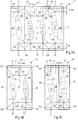
- Figure 2A shows a blank 1 'for producing a first embodiment of a packing jacket according to the invention.
- the ones already related to Figure 1A through 1F described areas of the blank are in Figure 2A provided with corresponding reference symbols.
- the bottom surface 8 and the gable surface 9 are off from the blank 1 Figure 1A unchanged.
- the four large surfaces 3, 4, 5, 6 are no longer separated from each other by a straight fold line 2; instead, the four large surfaces 3, 4, 5, 6 are separated from one another by two curved fold lines 2 ', between each of which a freeform surface 17 is arranged.
- Another difference is that the two side surfaces 3, 4 of the blank 1 ′ each have a dummy fold line 18.
- the two dummy fold lines 18 are straight and run parallel to one another.
- the dummy fold lines 18 run through a point of contact SB of three adjacent triangular surfaces 13 of the bottom surface 8 and through a point of contact SG of three adjacent triangular surfaces 13 of the gable surfaces 9.
- the bottom surfaces 8 have four corner points E8 and the gable surfaces 9 have four corner points E9.
- the corner points E8, E9 represent corner points of the packaging to be produced from the blank 1 '.
- Each corner point E8 of a bottom surface 8 is assigned a corresponding corner point E9 of a gable surface 9, which is the corner point E9 that is above this when the packaging is standing Corner point E8 is arranged.
- a corner axis EA runs through two mutually associated corner points E8, E9, which would correspond to a vertical packaging edge in the case of conventional cuboid packaging.
- the in Figure 2A The blank 1 'shown here are therefore - just as in the case of the package jacket produced therefrom and the packaging produced therefrom - four corner axes EA (for reasons of clarity, only one corner axis EA is always shown). No folding lines are provided between the corner points E8 of the floor surfaces 8 and the corner points E9 of the gable surfaces 9 assigned to them - that is, along the corner axes EA.
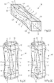
- Figure 2B shows a first embodiment of a packing jacket 10 'according to the invention, which consists of the in Figure 2A shown blank 1 'is formed, in a front view.
- the already related to Figures 1A to 2A described areas of the packing jacket are in Figure 2B provided with corresponding reference symbols.
- the package jacket 10 ' was created from the blank 1' in two steps: First, the blank 1 'is folded along the two dummy fold lines 18. Subsequently, the two partial areas 6A, 6B of the divided rear surface 6 are connected to one another in the area of the sealing surface 7, in particular welded, whereby a (in Figure 2B hidden) longitudinal seam 11 arises.
- the package jacket 1 'thus has a circumferential structure that is closed in the circumferential direction with an opening in the area of the bottom surface 8 and with an opening in the region of the gable surface 9.
- the edge of the longitudinal seam 11 running inside the pack jacket 10' is covered.
- the purpose of covering the open cut edge of the composite material is to avoid contact between the contents of the packaging and this layer, in particular the paper layer or cardboard layer contained therein.
- the cut edge is covered here by folding over the composite layer after prior peeling.
- the centrally located front surface 5 is visible, which is delimited on both sides by fold lines 2 '.
- Sub-areas 3A, 4A of the side surfaces 3, 4 can be seen laterally, which are also laterally bounded by fold lines 2 '.
- FIG 2C the packing jacket 1 'is off Figure 2B shown in a rear view.
- the ones already related to Figures 1A to 2B described areas of the packing jacket are in Figure 2C provided with corresponding reference symbols.
- the centrally located rear surface 6 is visible, which comprises two partial areas 6A, 6B connected by the longitudinal seam 11 and which is delimited on both sides by fold lines 2 '.
- Sub-areas 3B, 4B of the side surfaces 3, 4 can be seen laterally, which are also laterally delimited by fold lines 2 '.
- the remaining sub-areas 3A, 4A of the side surfaces 3, 4 are on the front side of the package jacket 10 'and therefore in Figure 2C covered.
- Open areas 17 are also provided on the rear side of the package jacket 10 'between the fold lines 2'.
- the free areas 17 are arranged in the areas of the packaging jacket 10 'which later form the (non-angular) "edges" of a packaging body.
- Figure 2D shows the packing jacket 1 ' Figures 2B and 2C in the unfolded state.
- the ones already related to Figures 1A to 2C described areas of the packing jacket are in Figure 2D provided with corresponding reference symbols.
- the unfolded state can be achieved by several folding steps: Firstly, the package jacket 10 ′ is folded along the fold lines 2 ′, which are arranged between the four large areas 3, 4, 5, 6 and the four open areas 17. Secondly, the package jacket 1 'is folded back along the dummy fold lines 18 running through the side surfaces 3, 4. The folded back takes place by approximately 180 °.
- the folding back along the note fold lines 18 has the consequence that the two partial areas 3A, 3B of the first side surface 3 adjoining the note fold line 18 no longer lie on top of one another, but are arranged in the same plane.
- the folding back along the note fold lines 18 has the consequence that the two partial areas 4A, 4B of the second side surface 4 adjoining the note fold line 18 no longer lie on top of one another, but are arranged in the same plane.
- the packing jacket 10 ' is therefore only in its flat state ( Figures 2B, 2C ) folded along the note fold lines 18; in the unfolded state ( Figure 2D ), however, the package jacket 10 ′ (like the package to be produced therefrom) is no longer folded along the dummy fold lines 18.
- FIG 2E the packing jacket 10 'is off Figure 2D shown with pre-folded base and gable surfaces.
- the ones already related to Figures 1A to 2D described areas of the packing jacket are in Figure 2E provided with corresponding reference symbols.
- the pre-folded state denotes (as in Figure 1D ) a state in which the fold lines 2 'have been pre-folded both in the area of the bottom surfaces 8 and in the area of the gable surfaces 9.
- Those areas of Floor surfaces 8 and the gable surfaces 9, which adjoin the front surface 5 and the rear surface 6, are also referred to as rectangular surfaces 12.
- the rectangular surfaces 12 are folded inward during the pre-folding and later form the bottom or the gable of the packaging.
- triangular surfaces 13 are folded outwards during the pre-folding and form protruding areas made of excess material, which are also referred to as "ears" 14 and are applied to the packaging in a later manufacturing step - for example by means of an adhesive process.
- FIG. 2E the packing jacket 10 'is also made of Figure 2D shown with pre-folded base and gable surfaces, which is why corresponding reference numerals are used here.
- the difference to Figure 2E lies in the fact that the triangular surfaces 13 are not folded outwards but inwards.
- Figure 2F shows a first embodiment of a packaging 15 'according to the invention, which consists of the in Figure 2B shown packing jacket 10 'is formed after welding.
- the ones already related to Figures 1A to 2E described areas of the packaging are in Figure 2E provided with corresponding reference symbols.
- the packaging 15 ' is shown after welding, that is to say in the filled and closed state.
- a fin seam 16 is created after the closure Figure 2F the ears 14 and the fin seam 16 protrude. Both the ears 14 and the fin seam 16 are created in a later manufacturing step, for example by gluing or welding processes.
- FIG. 2F ' also shows a first embodiment of a packaging 15 'according to the invention, which is derived from the in Figure 2B shown packing jacket 10 'is formed after welding. Corresponding reference symbols are therefore also used here.
- the difference to Figure 2F lies in the fact that the triangular surfaces 13 were not folded outwards, but inwards before welding. Hence the "ears" 14 do not extend outwards, but extend inwards. This leads to a shorter fin seam 15.
- FIG 2G the packaging is 15 'off Figure 2F shown with ears 14 attached.
- the ones already related to Figures 1A to 2F described areas of the packaging are in Figure 2G provided with corresponding reference symbols.
- the fin seams 16 are also placed on the packaging 15 '.
- the upper ears 14 arranged in the region of the gable surface 9 are folded down and laid flat against the two side surfaces 3, 4.
- the upper ears 14 are preferably glued or welded to the two side surfaces 3, 4.
- the lower ears 14 arranged in the area of the bottom surface 8 are also folded down, but placed flat against the underside of the packaging 15 ′, which is formed by two rectangular surfaces 12 of the bottom surface 8.
- the lower ears 14 are preferably also glued or welded to the packaging 15 ′ - in particular to the rectangular surfaces 12.
- the front surface 5 and the rear surface 6 are arranged parallel to one another.
- the two side surfaces 3, 4 are arranged parallel to one another. Angles of approximately 90 ° are formed between two adjacent surfaces of the four large surfaces 3, 4, 5, 6. However, the transition between the four large surfaces 3, 4, 5, 6 takes place (in contrast to the packaging 15 from Figure 1F ) not by angular edges, but by geometrically complex shaped open spaces 17.
- FIG. 2G ' the packaging is 15 'off Fig. 2F ' with the fin seam 15 applied.
- the fin seam 15 is folded over and laid flat against the underside of the packaging 15 ′, which is formed by two rectangular surfaces 12 of the bottom surface 8.
- the fin seam 15 is preferably glued or welded to the packaging 15 '- in particular to a rectangular surface 12.
- the difference to Figure 2G lies in the structure of the bottom of the package 15 ':
- the ears 14 are arranged below the rectangular surfaces 12 and are thus visible from the underside; in Fig. 2G ' however, the rectangular areas 12 are arranged below the ears 14 and are thus visible from the underside.
- FIG. 3A shows a blank 1 ′′ for producing a second embodiment of a packaging jacket according to the invention.
- the blank 1 ′′ in FIG Figure 3A largely corresponds to the 1 in Figure 2A so that corresponding reference symbols are used here as well.
- One difference lies in the shape of the gable surface 9: While the length L8 of the bottom surface 8 is constant over the entire width of the blank 1 ′′, the length of the gable surface 9 assumes different values. Adjacent to the rear surface 6, the gable surface 9 is reduced length L9 min. Adjacent to the front surface 5, the gable surface 9 on the other hand, an increased length L9 max. This configuration results in that the front face 5 has a lower height than the rear face 6.
- the side faces 3, 4 provide for a transition between the different heights of the front surface 5 and the rear surface 6, which is why the side surfaces 3, 4 in the blank 1 "(unlike the blank 1 and the blank 1 ') are not rectangular, but an inclined upper edge exhibit.
- the two side surfaces 3, 4 each have a dummy fold line 18.
- the two dummy fold lines 18 are straight and run parallel to one another.
- the dummy fold lines 18 run through a point of contact SB of three adjacent triangular surfaces 13 of the bottom surface 8 and through one Point of contact SG of three adjacent triangular surfaces 13 of the gable surfaces 9.
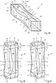
- FIG 3B is a second embodiment of a packing jacket 10 "according to the invention, which is composed of the in Figure 3A
- the blank 1 "shown is formed in a front view.
- the package jacket 10" in FIG Figure 3B largely corresponds to the packing jacket 10 'in Figure 2B so that corresponding reference symbols are used here as well.
- One difference lies in the increased length L9 max of the gable surface 9 in its area adjoining the front surface 5.
- Figure 3C shows the packing jacket 10 ′′ Figure 3B in a rear view.
- the packing jacket 10 "in Figure 3C largely corresponds to the packing jacket 10 'in Figure 2C so that corresponding reference symbols are used here as well.
- a difference lies in the reduced length L9 min of the gable surface 9 in its area adjoining the rear surface 6.
- FIG 3D the packing jacket is 10 "off Figures 3B and 3C shown in the unfolded state.
- the packing jacket 10 "in Figure 3D largely corresponds to the packing jacket 10 'in Figure 2D so that corresponding reference symbols are used here as well.
- a difference lies in the increased length L9 max of the gable surface 9 in its area adjoining the front surface 5 and in the reduced length L9 min of the gable surface 9 in its area adjoining the rear surface 6.
- Figure 3E shows the packing jacket 10 ′′ Figure 3D with pre-folded base and gable surfaces.
- the packing jacket 10 "in Figure 3E largely corresponds to the packing jacket 10 'in Figure 2E so that corresponding reference symbols are used here as well.
- a difference lies in the increased length L9 max of the gable surface 9 in its area adjoining the front surface 5 and in the reduced length L9 min of the gable surface 9 in its area adjoining the rear surface 6.
- FIG. 3E also shows the packing jacket 10 ′′ Figure 3D with pre-folded base and gable surfaces, which is why corresponding reference symbols are also used here.
- the difference to Figure 3E lies in the fact that the triangular surfaces 13 are not folded outwards but inwards.
- Figure 3F is a second embodiment of a packaging 15 "according to the invention, which consists of the in Figure 3B
- the package jacket 10 "shown is formed after welding.
- the package 15" in FIG Figure 3F largely corresponds to packaging 15 'in Figure 2F so that corresponding reference symbols are used here as well.
- the enlarged Length L9 max of the gable surface 9 leads to a large area which can be used for a pouring element 19.
- FIG. 3F ' is also a second embodiment of a packaging 15 "according to the invention, which is derived from the in Figure 3B Packing jacket 10 ′′ shown is formed after welding. Corresponding reference numerals are therefore used here as well Figure 3F lies in the fact that the triangular surfaces 13 were not folded outwards, but inwards before welding. The "ears" 14 therefore do not protrude outwards, but rather extend inwards. This leads to a shorter fin seam 15.
- Figure 3G shows the packaging 15 " Figure 3F with ears flat 14.
- the packing 15 "in Figure 3G largely corresponds to packaging 15 'in Figure 2G so that corresponding reference symbols are used here as well.
- the increased length L9 max of the gable surface 9 leads to a large area which can be used for a pouring element 19.
- FIG. 3G ' finally shows the packaging 15 ′′ Fig. 3F ' with the fin seam 15 applied.
- the fin seam 15 is folded over and laid flat on the underside of the packaging 15 ", which is formed by two rectangular surfaces 12 of the bottom surface 8.
- the fin seam 15 is preferably glued or welded to the packaging 15" - in particular to a rectangular surface 12.
- the difference to Figure 3G lies in the structure of the bottom of the packaging 15 ": In Figure 3G the ears 14 are arranged below the rectangular surfaces 12 and are thus visible from the underside; in Fig. 3G ' however, the rectangular areas 12 are arranged below the ears 14 and are thus visible from the underside.
Landscapes
- Engineering & Computer Science (AREA)
- Mechanical Engineering (AREA)
- Cartons (AREA)
- Bag Frames (AREA)
- Packages (AREA)
- Wrappers (AREA)
Claims (25)
- Enveloppe d'emballage (10', 10") en un matériau composite destinée à produire un emballage (15', 15"), comportant :- une surface avant (5),- une surface arrière (6),- deux surfaces latérales (3, 4),- des surfaces au sol (8) et des surfaces en pignon (9), lesquelles sont agencées sur les côtés opposés des deux surfaces latérales (3, 4), de la surface avant (5) et de la surface arrière (6), et- une couture longitudinale (11) qui relie les deux bords du matériau composite en une enveloppe d'emballage (10', 10") périphérique,- l'enveloppe d'emballage (10', 10") présentant plusieurs lignes de plissement (2, 2'),- les deux surfaces latérales (3, 4) présentant respectivement une ligne de plissement apparente (18) passant à travers les surfaces latérales (3, 4),- l'enveloppe d'emballage (10', 10") étant pliée exclusivement le long des deux lignes de plissement apparentes (18), et- l'enveloppe d'emballage (10', 10") étant ouverte dans la zone des surfaces au sol (8) et également dans la zone des surfaces en pignon (9),caractérisée en ce que
le matériau composite présente au moins une couche en papier ou en carton, laquelle est recouverte sur le bord de la couture longitudinale (11) passant à l'intérieur de l'enveloppe d'emballage (10', 10") et en ce que les lignes de plissement (2, 2') ne s'entrecroisent pas, mais gardent entre elles une distance minimale se situant entre 0,1 mm et 2,0 mm. - Enveloppe d'emballage selon la revendication 1,
caractérisée en ce que
au moins une des lignes de plissement (2, 2') passe au moins par sections de manière non droite et est, notamment, courbée ou pliée. - Enveloppe d'emballage selon la revendication 1 ou 2,
caractérisée en ce que
les surfaces au sol (8) présentent des sommets (E8) de l'emballage et en ce que les surfaces en pignon (9) présentent des sommets (E9) de l'emballage et en ce que l'on ne prévoit pas entre au moins un sommet (E8) des surfaces au sol (8) et un sommet (E9) des surfaces en pignon (9) lui étant associé une ligne de plissement (2, 2') entièrement droite. - Enveloppe d'emballage selon l'une des revendications 1 à 3,
caractérisée en ce que
l'enveloppe d'emballage (10', 10") est pliée à plat le long des deux lignes de plissement apparentes (18) selon un angle d'environ 180°. - Enveloppe d'emballage selon l'une des revendications 1 à 4,
caractérisée en ce que
les deux lignes de plissement apparentes (18) passent parallèlement l'une à l'autre. - Enveloppe d'emballage selon l'une des revendications 1 à 5,
caractérisée en ce que
les deux surfaces latérales (3, 4), la surface avant (5) et la surface arrière (6) sont délimitées par des lignes de plissement (2, 2'). - Enveloppe d'emballage selon l'une des revendications 1 à 6,
caractérisée en ce que
au moins une surface de forme libre (17) est agencée entre deux surfaces (3, 4, 5, 6) adjacentes provenant du groupe constitué par les deux surfaces latérales (3, 4), la surface avant (5) et la surface arrière (6). - Enveloppe d'emballage selon la revendication 7,
caractérisée en ce que
au moins une surface de forme libre (17) est délimitée par des lignes de plissement (2, 2'). - Enveloppe d'emballage selon l'une des revendications 1 à 8,
caractérisée en ce que
la surface en pignon (9) présente, adjacente à la surface arrière (6), une longueur plus faible (L9min) que la longueur (L9max) de la surface en pignon (9) adjacente à la surface avant (5). - Enveloppe d'emballage selon l'une des revendications 1 à 9,
caractérisée en ce que
les surfaces au sol (8) et les surfaces en pignon (9) comportent respectivement deux surfaces rectangulaires (12) et six surfaces triangulaires (13). - Enveloppe d'emballage selon la revendication 10,
caractérisée en ce que
les lignes de plissement apparentes (18) passent à travers le point de contact (SB) de trois surfaces triangulaires (13) adjacentes de la surface au sol (8) et à travers le point de contact (SG) de trois surfaces triangulaires (13) adjacentes des surfaces en pignon (9). - Enveloppe d'emballage selon l'une des revendications 1 à 11,
caractérisée en ce que
les lignes de plissement (2, 2') et/ou les lignes de plissement apparentes (18) sont façonnées à partir du côté intérieur vers le côté extérieur de l'enveloppe d'emballage (10', 10") et/ou du côté extérieur vers le côté intérieur de l'enveloppe d'emballage (10', 10"). - Enveloppe d'emballage selon l'une des revendications 1 à 12,
caractérisée en ce que
le matériau composite de l'enveloppe d'emballage (10', 10") présente une épaisseur comprise entre 150 g/m2 et 400 g/m2, notamment entre 200 g/m2 et 250 g/m2. - Enveloppe d'emballage selon l'une des revendications 1 à 13,
caractérisée en ce que
la couture longitudinale (11) relie mutuellement deux secteurs partiels (6A, 6B) de la surface arrière (6). - Enveloppe d'emballage selon la revendication 1,
caractérisée en ce que
la couche en papier ou en carton est recouverte par une bande d'étanchéité ou par la répartition du matériau composite dans la zone de la couture longitudinale (11). - Enveloppe d'emballage selon l'une des revendications 1 à 15,
caractérisée en ce que
le matériau composite est pelé sans la zone de la couture longitudinale (11). - Enveloppe d'emballage selon l'une des revendications 1 à 16,
caractérisée par
un affaiblissement du matériau, notamment un trou revêtu, dans une des surfaces en pignon (9) pour la fixation d'un bec verseur (19). - Emballage (15', 15") en un matériau composite- l'emballage (10', 10") étant plié le long des lignes de plissement (2, 2'),- l'emballage (10', 10") étant fermé dans la zone de la surface au sol (8) et dans la zone de la surface en pignon (9), et- les secteurs partiels (3A, 3B, 4A, 4B) des deux parois latérales (3, 4) adjacentes aux lignes de plissement apparentes (18) étant agencés l'un par rapport à l'autre respectivement dans une plage angulaire entre 160° et 200°, notamment entre 170° et 190°,caractérisé en ce que
l'emballage (15', 15") est fabriqué à partir d'une enveloppe d'emballage (10', 10") selon l'une des revendications 1 à 17. - Emballage selon la revendication 18,
caractérisé en ce que
la surface avant (5) et la surface arrière (6) sont agencées dans des plans étant approximativement parallèles l'un à l'autre. - Emballage selon la revendication 18 ou la revendication 19,
caractérisé en ce que
les deux surfaces latérales (3, 4) sont agencées dans des plans étant approximativement parallèles l'un à l'autre. - Emballage selon l'une des revendications 18 à 20,
caractérisé par
des pattes (14) qui sont placées dans la partie inférieure de l'emballage (15', 15") sur les surfaces au sol (8). - Emballage selon l'une des revendications 18 à 21,
caractérisé par
des pattes (14) qui sont placées dans la partie supérieure de l'emballage (15', 15") sur les surfaces latérales (3, 4). - Procédé de fabrication d'un emballage (15', 15") à partir d'une enveloppe d'emballage (10', 10") en un matériau composite, comportant les étapes suivantes :a) Mise à disposition d'une enveloppe d'emballage (10', 10") selon l'une des revendications de 1 à 17,b) Dépliage de l'enveloppe d'emballage (10', 10") le long de la ligne de plissement (2') entre les surfaces latérales (3, 4), la surface avant (5) et la surface arrière (6),c) Repliage des deux surfaces latérales (3, 4) de l'enveloppe d'emballage (10', 10") le long des deux lignes de plissement apparentes (18), etd) Scellage de l'enveloppe d'emballage (10', 10") dans la zone des surfaces au sol (8),caractérisé en ce que
l'étape d) est effectuée après l'étape b) et également après l'étape c). - Procédé selon la revendication 23,
caractérisé en ce que
les étapes b) et c) sont effectuées en même temps. - Procédé selon la revendication 23 ou la revendication 24,
caractérisé en ce que
les secteurs partiels (3A, 3B, 4A, 4B) d'une paroi latérale (3, 4) de l'emballage (15, 15') adjacents aux lignes de plissement apparentes (18) se situent, après le dépliage, à nouveau respectivement dans une plage angulaire entre 160° et 200°, notamment entre 170° et 190°.
Priority Applications (1)
| Application Number | Priority Date | Filing Date | Title |
|---|---|---|---|
| PL17711150T PL3439976T3 (pl) | 2016-04-04 | 2017-03-16 | Rękaw opakowaniowy, opakowanie i sposób wytwarzania opakowania |
Applications Claiming Priority (2)
| Application Number | Priority Date | Filing Date | Title |
|---|---|---|---|
| DE102016003826.8A DE102016003826A1 (de) | 2016-04-04 | 2016-04-04 | Packungsmantel, Verpackung und Verfahren zur Herstellung einer Verpackung |
| PCT/EP2017/056198 WO2017174317A1 (fr) | 2016-04-04 | 2017-03-16 | Enveloppe d'emballage, emballage et procédé de fabrication d'une enveloppe d'emballage |
Publications (2)
| Publication Number | Publication Date |
|---|---|
| EP3439976A1 EP3439976A1 (fr) | 2019-02-13 |
| EP3439976B1 true EP3439976B1 (fr) | 2021-02-17 |
Family
ID=58347361
Family Applications (1)
| Application Number | Title | Priority Date | Filing Date |
|---|---|---|---|
| EP17711150.7A Active EP3439976B1 (fr) | 2016-04-04 | 2017-03-16 | Enveloppe d'emballage, emballage et procédé de fabrication d'une enveloppe d'emballage |
Country Status (10)
| Country | Link |
|---|---|
| US (1) | US11299314B2 (fr) |
| EP (1) | EP3439976B1 (fr) |
| JP (1) | JP7108542B2 (fr) |
| CN (2) | CN207791404U (fr) |
| BR (1) | BR112018069462B8 (fr) |
| DE (1) | DE102016003826A1 (fr) |
| ES (1) | ES2863655T3 (fr) |
| MX (1) | MX2018010556A (fr) |
| PL (1) | PL3439976T3 (fr) |
| WO (1) | WO2017174317A1 (fr) |
Families Citing this family (27)
| Publication number | Priority date | Publication date | Assignee | Title |
|---|---|---|---|---|
| DE102016003826A1 (de) * | 2016-04-04 | 2017-10-05 | Sig Technology Ag | Packungsmantel, Verpackung und Verfahren zur Herstellung einer Verpackung |
| DE102016109979A1 (de) | 2016-04-04 | 2017-10-05 | Sig Technology Ag | Vorrichtung und Verfahren zum Formen von geschlossenen Verpackungen |
| WO2019127582A1 (fr) * | 2017-12-30 | 2019-07-04 | 厉彦明 | Découpe permettant de fabriquer un contenant d'emballage de liquide et contenant d'emballage associé |
| DE102018101336A1 (de) * | 2018-01-22 | 2019-07-25 | Melitta Single Portions Gmbh & Co. Kg | Verpackungseinheit |
| EP3556674B1 (fr) * | 2018-04-20 | 2022-09-14 | Tetra Laval Holdings & Finance S.A. | Matériau d'emballage en feuille pour la production d'un emballage scellé contenant un produit alimentaire fluide et emballage scellé obtenu à partir d'un matériau d'emballage en feuille |
| US20210147110A1 (en) * | 2018-04-27 | 2021-05-20 | Nippon Paper Industries Co., Ltd. | Paper container with stopper |
| EP3608243B1 (fr) * | 2018-08-06 | 2024-03-13 | Tetra Laval Holdings & Finance S.A. | Emballage en carton et découpe pour emballage en carton |
| US11667428B2 (en) * | 2018-11-20 | 2023-06-06 | Tetra Laval Holdings & Finance S.A. | Sheet packaging matertial for producing a sealed package containing a pourable product and a package obtained therefrom |
| DE102019110620A1 (de) * | 2019-04-24 | 2020-10-29 | Sig Technology Ag | System zum Verpacken mehrerer Gebinde auf einer Platte |
| JP7411375B2 (ja) * | 2019-10-15 | 2024-01-11 | 日本製紙株式会社 | 口栓付紙容器 |
| DE102019132429A1 (de) * | 2019-11-29 | 2021-06-02 | Sig Technology Ag | Flächenförmiges Verbundmaterial, Packungsmantel und Packung mit Entlastungspaneelen |
| DE102019132431A1 (de) | 2019-11-29 | 2021-06-02 | Sig Technology Ag | Packung mit geschwungenen Kanten |
| DE102019132430B4 (de) * | 2019-11-29 | 2025-02-20 | Sig Technology Ag | Flächenförmiges Verbundmaterial, Packungsmantel und Packung mit geschwungenen Kanten |
| DE102019132426B4 (de) * | 2019-11-29 | 2024-12-24 | Sig Technology Ag | Flächenförmiges Verbundmaterial, Packungsmantel und Packung mit trapezförmigem Giebel |
| DE102019132432A1 (de) | 2019-11-29 | 2021-06-02 | Sig Technology Ag | Packung mit Entlastungspanelen |
| EP4087786A1 (fr) | 2020-01-10 | 2022-11-16 | Elopak Asa | Récipient à base de papier ou de carton et procédés associés |
| EP3848298B1 (fr) | 2020-01-10 | 2026-02-11 | Elopak Asa | Récipient à base de papier ou de carton et procédé associé |
| GB2599944B (en) * | 2020-10-16 | 2024-11-06 | Ds Smith Plc | Method for customizing a blank |
| JP2024506101A (ja) | 2021-02-15 | 2024-02-08 | テトラ ラバル ホールディングス アンド ファイナンス エス エイ | 食品パッケージの横方向シールの品質を評価する方法 |
| NO349676B1 (en) | 2021-07-08 | 2026-03-30 | Elopak As | Paper-based or paperboard-based container and related method |
| CN113562286A (zh) * | 2021-08-26 | 2021-10-29 | 北京兰德瑞尔科技有限公司 | 可循环使用的包装容器 |
| CN117163437A (zh) * | 2022-05-26 | 2023-12-05 | 康美包(苏州)有限公司 | 包装用复合片材、包装用套筒、容器及其制作方法 |
| NO347782B1 (en) * | 2022-08-22 | 2024-03-25 | Elopak Asa | Paper-based or paperboard-based container and related method |
| IT202300016992A1 (it) * | 2023-08-08 | 2025-02-08 | Galdi S R L | Confezione per prodotto versabile e relativo procedimento di fabbricazione |
| EP4556388A1 (fr) * | 2023-11-15 | 2025-05-21 | Tetra Laval Holdings & Finance S.A. | Emballage rempli d'un produit versable et ébauche d'emballage pour former un emballage |
| IT202300024159A1 (it) * | 2023-11-15 | 2025-05-15 | Tetra Laval Holdings & Finance | Pacchetto riempito con un prodotto versabile e sbozzato di imballaggio per formare un pacchetto |
| CN118701455B (zh) * | 2024-08-27 | 2024-12-27 | 乐美包装(昆山)有限公司 | 柳叶型屋顶包包装片材 |
Citations (1)
| Publication number | Priority date | Publication date | Assignee | Title |
|---|---|---|---|---|
| DE4237859A1 (de) * | 1992-11-10 | 1994-05-11 | Pkl Verpackungssysteme Gmbh | Mantel für eine flüssigkeitsdichte Verpackung aus mit einer heißsiegelfähigen Kunststoffbeschichtung versehenem Kartonverbundmaterial und Verfahren zu dessen Herstellung |
Family Cites Families (50)
| Publication number | Priority date | Publication date | Assignee | Title |
|---|---|---|---|---|
| US734637A (en) * | 1902-06-04 | 1903-07-28 | Cornelius Vanderbilt | Truck-bolster. |
| US2050894A (en) * | 1934-05-29 | 1936-08-11 | Paige Richard Eaton | Folded blank box |
| GB808223A (en) | 1956-06-08 | 1959-01-28 | Metal Box Co Ltd | Improvements in or relating to cartons |
| US3610514A (en) * | 1969-06-13 | 1971-10-05 | Gillette Co | Diamond-shaped carton having fifth side |
| JPS489626Y1 (fr) | 1970-07-01 | 1973-03-14 | ||
| US3866523A (en) | 1973-05-30 | 1975-02-18 | Lancaster Research And Dev Cor | Method and apparatus for forming bulk containers from articulatable composite panels |
| EP0027350A1 (fr) | 1979-10-12 | 1981-04-22 | Visymonde Investments Pte. Ltd. | Récipients et gaines, en particulier récipients et gaines obtenus par pliage d'un matériau en feuille |
| SE432918B (sv) | 1979-10-18 | 1984-04-30 | Tetra Pak Int | Biglinjeforsett forpackningslaminat |
| JPS6169544A (ja) | 1984-09-13 | 1986-04-10 | 十條製紙株式会社 | 液体用厚紙容器のブランク |
| JPH0732417Y2 (ja) | 1987-01-16 | 1995-07-26 | 四国化工機株式会社 | 紙主体積層体製近似直方体状液体密封容器 |
| JPS63123421U (fr) * | 1987-02-04 | 1988-08-11 | ||
| SE502398C2 (sv) | 1991-03-07 | 1995-10-16 | Tetra Laval Holdings & Finance | Kantförstärkt förpackningsbehållare |
| US5848749A (en) * | 1994-05-06 | 1998-12-15 | Tetra Laval Holdings & Finance, Sa | Gable top carton and carton blank with curved side creases and coincident corner creases |
| US5704886A (en) | 1995-06-02 | 1998-01-06 | International Paper Company | Method and apparatus for scoring paperboard package sheets |
| IT1285595B1 (it) | 1996-03-06 | 1998-06-18 | Catta 27 S R L | Fustellato di contenitore per prodotti liquidi, granulari o polverulenti e metodo per l'utilizzo del medesimo fustellato nella |
| US5738272A (en) * | 1996-03-21 | 1998-04-14 | Tetra Laval Holdings & Finance S.A. | Gable top carton and carton blank having reduced surface area per unit volume |
| BR9612668A (pt) | 1996-03-21 | 1999-07-20 | Tetra Laval Holdings & Finance | Recipiente em forma de pacote e um molde para a produção do mesmo |
| US5871144A (en) * | 1997-07-29 | 1999-02-16 | Tetra Laval Holdings & Finance Sa | Eight sided gable top carton |
| JPH1191727A (ja) | 1997-09-22 | 1999-04-06 | Toppan Printing Co Ltd | 液体包装用紙製角筒容器の成形方法 |
| US6042527A (en) | 1998-01-30 | 2000-03-28 | Tetra Laval Holdings & Finance, Sa | Carton forming device |
| DK0936150T3 (da) | 1998-02-13 | 2004-07-19 | Tetra Laval Holdings & Finance | For-foldet emballeringsarkmateriale til emballering af hældbare födevarer og emballager fremstillet derved |
| DE19945500C2 (de) | 1998-09-22 | 2003-05-22 | Sig Combibloc Gmbh | Verfahren und Vorrichtung zum Entkeimen von Behältern in einer Füllmaschine |
| EP1080880A1 (fr) * | 1999-08-20 | 2001-03-07 | Alusuisse Technology & Management AG | Matériaux d'emballage avec couche de matériau sélectivement disposée |
| JP2001130543A (ja) | 1999-11-02 | 2001-05-15 | Furubayashi Shiko Co Ltd | 曲面カートン |
| JP2002067192A (ja) | 2000-09-01 | 2002-03-05 | Toppan Printing Co Ltd | 液体用紙容器のエッジプロテクト加工方法 |
| JP2001213427A (ja) | 2000-11-29 | 2001-08-07 | Dainippon Printing Co Ltd | 紙容器 |
| KR200282152Y1 (ko) | 2002-04-18 | 2002-07-22 | 문광열 | 액체 포장용기 및 그 포재 |
| CN2540378Y (zh) * | 2002-05-14 | 2003-03-19 | Sig孔比布劳克系统有限公司 | 容器 |
| JP4442796B2 (ja) * | 2003-01-24 | 2010-03-31 | 日本テトラパック株式会社 | 包装容器および包装容器に取付けられる注ぎ栓 |
| DE202004010230U1 (de) * | 2004-06-29 | 2004-09-30 | Henkel Kgaa | Faltschachtel |
| EP1851120B1 (fr) * | 2005-01-29 | 2018-05-09 | Elopak Systems Ag | Conteneur, ébauche, mandrin et procédé de fabrication du conteneur |
| US7523853B2 (en) * | 2007-05-29 | 2009-04-28 | Tetra Laval Holdings & Finance. S.A. | Carton and blank for carton with corner indent wall |
| USD578389S1 (en) * | 2008-01-22 | 2008-10-14 | Evergreen Packaging Inc. | Carton |
| USD601016S1 (en) * | 2008-01-22 | 2009-09-29 | Evergreen Packaging Inc. | Carton |
| GB0802518D0 (en) * | 2008-02-12 | 2008-03-19 | Elopak Systems | Container made of material, blank and methods |
| FR2928358B1 (fr) * | 2008-03-05 | 2012-11-16 | Finega | Etui de conditionnement automatisable et flan predecoupe pour sa realisation. |
| GB0809082D0 (en) * | 2008-05-20 | 2008-06-25 | Elopak Systems | Improvements in or relating to container blanks and containers |
| JP2010018283A (ja) | 2008-07-08 | 2010-01-28 | Nihon Tetra Pak Kk | 包装容器用ストリップ及び紙包装容器 |
| DE102009024318A1 (de) * | 2008-11-28 | 2010-06-02 | Sig Technology Ag | Verfahren und Vorrichtung zur Herstellung von behälterartigen Verbundverpackungen |
| CN101875420B (zh) | 2009-04-30 | 2014-06-18 | 翁文桂 | 一种阻隔性叠层包装材料 |
| EP2392517A1 (fr) * | 2010-06-07 | 2011-12-07 | Tetra Laval Holdings & Finance S.A. | Emballage scellé pour produits alimentaires versables et matériau de conditionnement pour produire des emballages scellés de produits alimentaires versables |
| DE102010033466B4 (de) | 2010-08-05 | 2012-11-08 | Sig Technology Ag | Verpackungsbehälter aus einem flächenförmigen Verbund mit verbesserter Haft- und Innenschichtkombination |
| US8950655B2 (en) | 2010-12-07 | 2015-02-10 | Tetra Laval Holdings & Finance, S.A. | Method of manufacturing packaging container and packaging container |
| USD728364S1 (en) * | 2013-03-15 | 2015-05-05 | Big Heart Pet Brands | Packages |
| DE102013107223B4 (de) | 2013-07-09 | 2017-12-07 | Sig Technology Ag | Vorrichtung und Verfahren zum Auffalten, Befüllen und Verschließen von Packungsmänteln |
| CA170844S (en) * | 2013-11-15 | 2020-02-03 | Elopak Systems | Carton sleeve |
| EP2957509A1 (fr) | 2014-06-17 | 2015-12-23 | Tetra Laval Holdings & Finance S.A. | Procédé permettant de fournir des lignes de pli |
| USD803682S1 (en) * | 2015-06-18 | 2017-11-28 | Tetra Laval Holdings & Finance S.A. | Blank for packaging |
| DE102016003826A1 (de) * | 2016-04-04 | 2017-10-05 | Sig Technology Ag | Packungsmantel, Verpackung und Verfahren zur Herstellung einer Verpackung |
| DE102016003827A1 (de) | 2016-04-04 | 2017-10-05 | Sig Technology Ag | Zuschnitt, Packungsmantel, Verpackung und Verfahren zur Herstellung eines Zuschnitts, eines Packungsmantels und einer Verpackung |
-
2016
- 2016-04-04 DE DE102016003826.8A patent/DE102016003826A1/de not_active Ceased
-
2017
- 2017-03-16 WO PCT/EP2017/056198 patent/WO2017174317A1/fr not_active Ceased
- 2017-03-16 ES ES17711150T patent/ES2863655T3/es active Active
- 2017-03-16 MX MX2018010556A patent/MX2018010556A/es unknown
- 2017-03-16 EP EP17711150.7A patent/EP3439976B1/fr active Active
- 2017-03-16 BR BR112018069462A patent/BR112018069462B8/pt active IP Right Grant
- 2017-03-16 JP JP2018552068A patent/JP7108542B2/ja active Active
- 2017-03-16 PL PL17711150T patent/PL3439976T3/pl unknown
- 2017-03-16 US US16/087,825 patent/US11299314B2/en active Active
- 2017-04-01 CN CN201720342073.8U patent/CN207791404U/zh not_active Withdrawn - After Issue
- 2017-04-01 CN CN201710213765.7A patent/CN107264911B/zh active Active
Patent Citations (1)
| Publication number | Priority date | Publication date | Assignee | Title |
|---|---|---|---|---|
| DE4237859A1 (de) * | 1992-11-10 | 1994-05-11 | Pkl Verpackungssysteme Gmbh | Mantel für eine flüssigkeitsdichte Verpackung aus mit einer heißsiegelfähigen Kunststoffbeschichtung versehenem Kartonverbundmaterial und Verfahren zu dessen Herstellung |
Also Published As
| Publication number | Publication date |
|---|---|
| CN107264911B (zh) | 2020-10-27 |
| MX2018010556A (es) | 2018-11-09 |
| BR112018069462B8 (pt) | 2023-01-03 |
| BR112018069462A2 (pt) | 2019-02-05 |
| EP3439976A1 (fr) | 2019-02-13 |
| JP2019510702A (ja) | 2019-04-18 |
| DE102016003826A1 (de) | 2017-10-05 |
| CN107264911A (zh) | 2017-10-20 |
| US11299314B2 (en) | 2022-04-12 |
| ES2863655T3 (es) | 2021-10-11 |
| PL3439976T3 (pl) | 2021-07-05 |
| BR112018069462B1 (pt) | 2022-08-23 |
| JP7108542B2 (ja) | 2022-07-28 |
| US20190106239A1 (en) | 2019-04-11 |
| WO2017174317A1 (fr) | 2017-10-12 |
| CN207791404U (zh) | 2018-08-31 |
Similar Documents
| Publication | Publication Date | Title |
|---|---|---|
| EP3439976B1 (fr) | Enveloppe d'emballage, emballage et procédé de fabrication d'une enveloppe d'emballage | |
| EP3439975B1 (fr) | Enveloppe d'emballage, emballage et procédé de fabrication d'une enveloppe d'emballage | |
| EP3439977B1 (fr) | Enveloppe d'emballage, emballage et procédé de fabrication d'un emballage | |
| DE69121910T2 (de) | Behälter aus Folienmaterial und Zuschnitt zur Herstellung desselben | |
| EP0407746B1 (fr) | Réceptacle parallélépipédique à sommet en forme de toit avec un bec verseur sur le toit plat | |
| EP3439978B1 (fr) | Flan, enveloppe d'emballage, emballage et procédé de fabrication d'un flan, d'une enveloppe d'emballage et d'un emballage | |
| WO2017174347A1 (fr) | Dispositif et procédé pour façonner des emballages fermés | |
| EP4065480B1 (fr) | Carton comprenant des panneaux de relâchement des contraintes | |
| EP4065477B1 (fr) | Matériau composite plat, boîtier d'emballage et emballage à bords incurvés | |
| EP4065479B1 (fr) | Matériau composite plat, boîtier d'emballage et emballage doté de panneaux de support | |
| EP4065476B1 (fr) | Matériau composite plan, manchon de paquet et paquet à pignon trapézoïdal | |
| WO2019068384A1 (fr) | Enveloppe d'emballage, emballage et procédé de fabrication d'un emballage | |
| EP3728063B1 (fr) | Paquet composé d'enveloppes d'emballage et d'un suremballage | |
| DE3619407C2 (fr) | ||
| DE69700773T2 (de) | Dose und Vorrichtung zu deren Herstellung | |
| DE102017123011A1 (de) | Packungsmantel, Verpackung und Verfahren zur Herstellung einer Verpackung | |
| EP0525160B1 (fr) | Boite pliante avec un sachet interieur et procede pour sa fabrication | |
| CH398444A (de) | Flachlegbare und aufrichtbare Faltschachtel | |
| DE3927561A1 (de) | Verpackung sowie zuschnitt und verfahren zur herstellung derselben | |
| DE102017123010A1 (de) | Packungsmantel, Verpackung und Verfahren zur Herstellung einer Verpackung | |
| DE20203152U1 (de) | Verpackung | |
| DE3734389C2 (fr) | ||
| EP0780312B1 (fr) | Emballage en carton | |
| DE3741312C2 (de) | Quaderförmige Giebelpackung | |
| DE3719038A1 (de) | Giebelpackung |
Legal Events
| Date | Code | Title | Description |
|---|---|---|---|
| STAA | Information on the status of an ep patent application or granted ep patent |
Free format text: STATUS: UNKNOWN |
|
| STAA | Information on the status of an ep patent application or granted ep patent |
Free format text: STATUS: THE INTERNATIONAL PUBLICATION HAS BEEN MADE |
|
| PUAI | Public reference made under article 153(3) epc to a published international application that has entered the european phase |
Free format text: ORIGINAL CODE: 0009012 |
|
| STAA | Information on the status of an ep patent application or granted ep patent |
Free format text: STATUS: REQUEST FOR EXAMINATION WAS MADE |
|
| 17P | Request for examination filed |
Effective date: 20180814 |
|
| AK | Designated contracting states |
Kind code of ref document: A1 Designated state(s): AL AT BE BG CH CY CZ DE DK EE ES FI FR GB GR HR HU IE IS IT LI LT LU LV MC MK MT NL NO PL PT RO RS SE SI SK SM TR |
|
| AX | Request for extension of the european patent |
Extension state: BA ME |
|
| DAV | Request for validation of the european patent (deleted) | ||
| DAX | Request for extension of the european patent (deleted) | ||
| STAA | Information on the status of an ep patent application or granted ep patent |
Free format text: STATUS: EXAMINATION IS IN PROGRESS |
|
| 17Q | First examination report despatched |
Effective date: 20190822 |
|
| GRAP | Despatch of communication of intention to grant a patent |
Free format text: ORIGINAL CODE: EPIDOSNIGR1 |
|
| STAA | Information on the status of an ep patent application or granted ep patent |
Free format text: STATUS: GRANT OF PATENT IS INTENDED |
|
| INTG | Intention to grant announced |
Effective date: 20200909 |
|
| GRAS | Grant fee paid |
Free format text: ORIGINAL CODE: EPIDOSNIGR3 |
|
| GRAA | (expected) grant |
Free format text: ORIGINAL CODE: 0009210 |
|
| STAA | Information on the status of an ep patent application or granted ep patent |
Free format text: STATUS: THE PATENT HAS BEEN GRANTED |
|
| AK | Designated contracting states |
Kind code of ref document: B1 Designated state(s): AL AT BE BG CH CY CZ DE DK EE ES FI FR GB GR HR HU IE IS IT LI LT LU LV MC MK MT NL NO PL PT RO RS SE SI SK SM TR |
|
| REG | Reference to a national code |
Ref country code: GB Ref legal event code: FG4D Free format text: NOT ENGLISH |
|
| REG | Reference to a national code |
Ref country code: CH Ref legal event code: EP |
|
| REG | Reference to a national code |
Ref country code: DE Ref legal event code: R096 Ref document number: 502017009344 Country of ref document: DE |
|
| REG | Reference to a national code |
Ref country code: AT Ref legal event code: REF Ref document number: 1361168 Country of ref document: AT Kind code of ref document: T Effective date: 20210315 |
|
| REG | Reference to a national code |
Ref country code: IE Ref legal event code: FG4D Free format text: LANGUAGE OF EP DOCUMENT: GERMAN |
|
| REG | Reference to a national code |
Ref country code: LT Ref legal event code: MG9D |
|
| REG | Reference to a national code |
Ref country code: NL Ref legal event code: MP Effective date: 20210217 |
|
| PG25 | Lapsed in a contracting state [announced via postgrant information from national office to epo] |
Ref country code: PT Free format text: LAPSE BECAUSE OF FAILURE TO SUBMIT A TRANSLATION OF THE DESCRIPTION OR TO PAY THE FEE WITHIN THE PRESCRIBED TIME-LIMIT Effective date: 20210617 Ref country code: NO Free format text: LAPSE BECAUSE OF FAILURE TO SUBMIT A TRANSLATION OF THE DESCRIPTION OR TO PAY THE FEE WITHIN THE PRESCRIBED TIME-LIMIT Effective date: 20210517 Ref country code: FI Free format text: LAPSE BECAUSE OF FAILURE TO SUBMIT A TRANSLATION OF THE DESCRIPTION OR TO PAY THE FEE WITHIN THE PRESCRIBED TIME-LIMIT Effective date: 20210217 Ref country code: HR Free format text: LAPSE BECAUSE OF FAILURE TO SUBMIT A TRANSLATION OF THE DESCRIPTION OR TO PAY THE FEE WITHIN THE PRESCRIBED TIME-LIMIT Effective date: 20210217 Ref country code: GR Free format text: LAPSE BECAUSE OF FAILURE TO SUBMIT A TRANSLATION OF THE DESCRIPTION OR TO PAY THE FEE WITHIN THE PRESCRIBED TIME-LIMIT Effective date: 20210518 Ref country code: LT Free format text: LAPSE BECAUSE OF FAILURE TO SUBMIT A TRANSLATION OF THE DESCRIPTION OR TO PAY THE FEE WITHIN THE PRESCRIBED TIME-LIMIT Effective date: 20210217 Ref country code: BG Free format text: LAPSE BECAUSE OF FAILURE TO SUBMIT A TRANSLATION OF THE DESCRIPTION OR TO PAY THE FEE WITHIN THE PRESCRIBED TIME-LIMIT Effective date: 20210517 |
|
| PG25 | Lapsed in a contracting state [announced via postgrant information from national office to epo] |
Ref country code: NL Free format text: LAPSE BECAUSE OF FAILURE TO SUBMIT A TRANSLATION OF THE DESCRIPTION OR TO PAY THE FEE WITHIN THE PRESCRIBED TIME-LIMIT Effective date: 20210217 Ref country code: LV Free format text: LAPSE BECAUSE OF FAILURE TO SUBMIT A TRANSLATION OF THE DESCRIPTION OR TO PAY THE FEE WITHIN THE PRESCRIBED TIME-LIMIT Effective date: 20210217 Ref country code: RS Free format text: LAPSE BECAUSE OF FAILURE TO SUBMIT A TRANSLATION OF THE DESCRIPTION OR TO PAY THE FEE WITHIN THE PRESCRIBED TIME-LIMIT Effective date: 20210217 Ref country code: SE Free format text: LAPSE BECAUSE OF FAILURE TO SUBMIT A TRANSLATION OF THE DESCRIPTION OR TO PAY THE FEE WITHIN THE PRESCRIBED TIME-LIMIT Effective date: 20210217 |
|
| PG25 | Lapsed in a contracting state [announced via postgrant information from national office to epo] |
Ref country code: IS Free format text: LAPSE BECAUSE OF FAILURE TO SUBMIT A TRANSLATION OF THE DESCRIPTION OR TO PAY THE FEE WITHIN THE PRESCRIBED TIME-LIMIT Effective date: 20210617 |
|
| REG | Reference to a national code |
Ref country code: ES Ref legal event code: FG2A Ref document number: 2863655 Country of ref document: ES Kind code of ref document: T3 Effective date: 20211011 |
|
| PG25 | Lapsed in a contracting state [announced via postgrant information from national office to epo] |
Ref country code: EE Free format text: LAPSE BECAUSE OF FAILURE TO SUBMIT A TRANSLATION OF THE DESCRIPTION OR TO PAY THE FEE WITHIN THE PRESCRIBED TIME-LIMIT Effective date: 20210217 Ref country code: CZ Free format text: LAPSE BECAUSE OF FAILURE TO SUBMIT A TRANSLATION OF THE DESCRIPTION OR TO PAY THE FEE WITHIN THE PRESCRIBED TIME-LIMIT Effective date: 20210217 Ref country code: SM Free format text: LAPSE BECAUSE OF FAILURE TO SUBMIT A TRANSLATION OF THE DESCRIPTION OR TO PAY THE FEE WITHIN THE PRESCRIBED TIME-LIMIT Effective date: 20210217 |
|
| REG | Reference to a national code |
Ref country code: CH Ref legal event code: PL |
|
| REG | Reference to a national code |
Ref country code: DE Ref legal event code: R097 Ref document number: 502017009344 Country of ref document: DE |
|
| PG25 | Lapsed in a contracting state [announced via postgrant information from national office to epo] |
Ref country code: SK Free format text: LAPSE BECAUSE OF FAILURE TO SUBMIT A TRANSLATION OF THE DESCRIPTION OR TO PAY THE FEE WITHIN THE PRESCRIBED TIME-LIMIT Effective date: 20210217 Ref country code: DK Free format text: LAPSE BECAUSE OF FAILURE TO SUBMIT A TRANSLATION OF THE DESCRIPTION OR TO PAY THE FEE WITHIN THE PRESCRIBED TIME-LIMIT Effective date: 20210217 Ref country code: RO Free format text: LAPSE BECAUSE OF FAILURE TO SUBMIT A TRANSLATION OF THE DESCRIPTION OR TO PAY THE FEE WITHIN THE PRESCRIBED TIME-LIMIT Effective date: 20210217 Ref country code: MC Free format text: LAPSE BECAUSE OF FAILURE TO SUBMIT A TRANSLATION OF THE DESCRIPTION OR TO PAY THE FEE WITHIN THE PRESCRIBED TIME-LIMIT Effective date: 20210217 |
|
| REG | Reference to a national code |
Ref country code: BE Ref legal event code: MM Effective date: 20210331 |
|
| PLBE | No opposition filed within time limit |
Free format text: ORIGINAL CODE: 0009261 |
|
| STAA | Information on the status of an ep patent application or granted ep patent |
Free format text: STATUS: NO OPPOSITION FILED WITHIN TIME LIMIT |
|
| 26N | No opposition filed |
Effective date: 20211118 |
|
| PG25 | Lapsed in a contracting state [announced via postgrant information from national office to epo] |
Ref country code: IE Free format text: LAPSE BECAUSE OF NON-PAYMENT OF DUE FEES Effective date: 20210316 Ref country code: LI Free format text: LAPSE BECAUSE OF NON-PAYMENT OF DUE FEES Effective date: 20210331 Ref country code: LU Free format text: LAPSE BECAUSE OF NON-PAYMENT OF DUE FEES Effective date: 20210316 Ref country code: CH Free format text: LAPSE BECAUSE OF NON-PAYMENT OF DUE FEES Effective date: 20210331 Ref country code: AL Free format text: LAPSE BECAUSE OF FAILURE TO SUBMIT A TRANSLATION OF THE DESCRIPTION OR TO PAY THE FEE WITHIN THE PRESCRIBED TIME-LIMIT Effective date: 20210217 |
|
| PG25 | Lapsed in a contracting state [announced via postgrant information from national office to epo] |
Ref country code: SI Free format text: LAPSE BECAUSE OF FAILURE TO SUBMIT A TRANSLATION OF THE DESCRIPTION OR TO PAY THE FEE WITHIN THE PRESCRIBED TIME-LIMIT Effective date: 20210217 |
|
| PG25 | Lapsed in a contracting state [announced via postgrant information from national office to epo] |
Ref country code: IS Free format text: LAPSE BECAUSE OF FAILURE TO SUBMIT A TRANSLATION OF THE DESCRIPTION OR TO PAY THE FEE WITHIN THE PRESCRIBED TIME-LIMIT Effective date: 20210617 |
|
| PG25 | Lapsed in a contracting state [announced via postgrant information from national office to epo] |
Ref country code: BE Free format text: LAPSE BECAUSE OF NON-PAYMENT OF DUE FEES Effective date: 20210331 |
|
| REG | Reference to a national code |
Ref country code: AT Ref legal event code: MM01 Ref document number: 1361168 Country of ref document: AT Kind code of ref document: T Effective date: 20220316 |
|
| PG25 | Lapsed in a contracting state [announced via postgrant information from national office to epo] |
Ref country code: CY Free format text: LAPSE BECAUSE OF FAILURE TO SUBMIT A TRANSLATION OF THE DESCRIPTION OR TO PAY THE FEE WITHIN THE PRESCRIBED TIME-LIMIT Effective date: 20210217 |
|
| PG25 | Lapsed in a contracting state [announced via postgrant information from national office to epo] |
Ref country code: HU Free format text: LAPSE BECAUSE OF FAILURE TO SUBMIT A TRANSLATION OF THE DESCRIPTION OR TO PAY THE FEE WITHIN THE PRESCRIBED TIME-LIMIT; INVALID AB INITIO Effective date: 20170316 Ref country code: AT Free format text: LAPSE BECAUSE OF NON-PAYMENT OF DUE FEES Effective date: 20220316 |
|
| REG | Reference to a national code |
Ref country code: GB Ref legal event code: 732E Free format text: REGISTERED BETWEEN 20230713 AND 20230719 |
|
| REG | Reference to a national code |
Ref country code: ES Ref legal event code: PC2A Owner name: SIG COMBIBLOC SERVICES AG Effective date: 20231130 |
|
| PG25 | Lapsed in a contracting state [announced via postgrant information from national office to epo] |
Ref country code: MK Free format text: LAPSE BECAUSE OF FAILURE TO SUBMIT A TRANSLATION OF THE DESCRIPTION OR TO PAY THE FEE WITHIN THE PRESCRIBED TIME-LIMIT Effective date: 20210217 |
|
| REG | Reference to a national code |
Ref country code: ES Ref legal event code: PC2A Owner name: SIG SERVICES AG Effective date: 20240906 |
|
| PG25 | Lapsed in a contracting state [announced via postgrant information from national office to epo] |
Ref country code: MT Free format text: LAPSE BECAUSE OF FAILURE TO SUBMIT A TRANSLATION OF THE DESCRIPTION OR TO PAY THE FEE WITHIN THE PRESCRIBED TIME-LIMIT Effective date: 20210217 |
|
| REG | Reference to a national code |
Ref country code: DE Ref legal event code: R081 Ref document number: 502017009344 Country of ref document: DE Owner name: SIG SERVICES AG, CH Free format text: FORMER OWNER: SIG TECHNOLOGY AG, NEUHAUSEN AM RHEINFALL, CH |
|
| PGFP | Annual fee paid to national office [announced via postgrant information from national office to epo] |
Ref country code: PL Payment date: 20250304 Year of fee payment: 9 |
|
| PGFP | Annual fee paid to national office [announced via postgrant information from national office to epo] |
Ref country code: ES Payment date: 20250416 Year of fee payment: 9 |
|
| PGFP | Annual fee paid to national office [announced via postgrant information from national office to epo] |
Ref country code: IT Payment date: 20250331 Year of fee payment: 9 |
|
| PGFP | Annual fee paid to national office [announced via postgrant information from national office to epo] |
Ref country code: GB Payment date: 20260324 Year of fee payment: 10 |
|
| PGFP | Annual fee paid to national office [announced via postgrant information from national office to epo] |
Ref country code: DE Payment date: 20260320 Year of fee payment: 10 |
|
| PGFP | Annual fee paid to national office [announced via postgrant information from national office to epo] |
Ref country code: FR Payment date: 20260324 Year of fee payment: 10 |
|
| PGFP | Annual fee paid to national office [announced via postgrant information from national office to epo] |
Ref country code: TR Payment date: 20260306 Year of fee payment: 10 |