EP3442019A1 - Leistungsmodul - Google Patents
Leistungsmodul Download PDFInfo
- Publication number
- EP3442019A1 EP3442019A1 EP16892932.1A EP16892932A EP3442019A1 EP 3442019 A1 EP3442019 A1 EP 3442019A1 EP 16892932 A EP16892932 A EP 16892932A EP 3442019 A1 EP3442019 A1 EP 3442019A1
- Authority
- EP
- European Patent Office
- Prior art keywords
- current
- mosfet
- power module
- circuit
- semiconductor device
- Prior art date
- Legal status (The legal status is an assumption and is not a legal conclusion. Google has not performed a legal analysis and makes no representation as to the accuracy of the status listed.)
- Withdrawn
Links
Images


Classifications
-
- H—ELECTRICITY
- H02—GENERATION; CONVERSION OR DISTRIBUTION OF ELECTRIC POWER
- H02H—EMERGENCY PROTECTIVE CIRCUIT ARRANGEMENTS
- H02H3/00—Emergency protective circuit arrangements for automatic disconnection directly responsive to an undesired change from normal electric working condition with or without subsequent reconnection ; integrated protection
- H02H3/08—Emergency protective circuit arrangements for automatic disconnection directly responsive to an undesired change from normal electric working condition with or without subsequent reconnection ; integrated protection responsive to excess current
- H02H3/085—Emergency protective circuit arrangements for automatic disconnection directly responsive to an undesired change from normal electric working condition with or without subsequent reconnection ; integrated protection responsive to excess current making use of a thermal sensor, e.g. thermistor, heated by the excess current
-
- H—ELECTRICITY
- H02—GENERATION; CONVERSION OR DISTRIBUTION OF ELECTRIC POWER
- H02H—EMERGENCY PROTECTIVE CIRCUIT ARRANGEMENTS
- H02H3/00—Emergency protective circuit arrangements for automatic disconnection directly responsive to an undesired change from normal electric working condition with or without subsequent reconnection ; integrated protection
- H02H3/02—Details
- H02H3/05—Details with means for increasing reliability, e.g. redundancy arrangements
-
- H—ELECTRICITY
- H02—GENERATION; CONVERSION OR DISTRIBUTION OF ELECTRIC POWER
- H02H—EMERGENCY PROTECTIVE CIRCUIT ARRANGEMENTS
- H02H3/00—Emergency protective circuit arrangements for automatic disconnection directly responsive to an undesired change from normal electric working condition with or without subsequent reconnection ; integrated protection
- H02H3/08—Emergency protective circuit arrangements for automatic disconnection directly responsive to an undesired change from normal electric working condition with or without subsequent reconnection ; integrated protection responsive to excess current
-
- H—ELECTRICITY
- H02—GENERATION; CONVERSION OR DISTRIBUTION OF ELECTRIC POWER
- H02H—EMERGENCY PROTECTIVE CIRCUIT ARRANGEMENTS
- H02H7/00—Emergency protective circuit arrangements specially adapted for specific types of electric machines or apparatus or for sectionalised protection of cable or line systems, and effecting automatic switching in the event of an undesired change from normal working conditions
- H02H7/22—Emergency protective circuit arrangements specially adapted for specific types of electric machines or apparatus or for sectionalised protection of cable or line systems, and effecting automatic switching in the event of an undesired change from normal working conditions for distribution gear, e.g. bus-bar systems; for switching devices
- H02H7/222—Emergency protective circuit arrangements specially adapted for specific types of electric machines or apparatus or for sectionalised protection of cable or line systems, and effecting automatic switching in the event of an undesired change from normal working conditions for distribution gear, e.g. bus-bar systems; for switching devices for switches
-
- H—ELECTRICITY
- H02—GENERATION; CONVERSION OR DISTRIBUTION OF ELECTRIC POWER
- H02M—APPARATUS FOR CONVERSION BETWEEN AC AND AC, BETWEEN AC AND DC, OR BETWEEN DC AND DC, AND FOR USE WITH MAINS OR SIMILAR POWER SUPPLY SYSTEMS; CONVERSION OF DC OR AC INPUT POWER INTO SURGE OUTPUT POWER; CONTROL OR REGULATION THEREOF
- H02M1/00—Details of apparatus for conversion
- H02M1/08—Circuits specially adapted for the generation of control voltages for semiconductor devices incorporated in static converters
-
- H—ELECTRICITY
- H02—GENERATION; CONVERSION OR DISTRIBUTION OF ELECTRIC POWER
- H02M—APPARATUS FOR CONVERSION BETWEEN AC AND AC, BETWEEN AC AND DC, OR BETWEEN DC AND DC, AND FOR USE WITH MAINS OR SIMILAR POWER SUPPLY SYSTEMS; CONVERSION OF DC OR AC INPUT POWER INTO SURGE OUTPUT POWER; CONTROL OR REGULATION THEREOF
- H02M1/00—Details of apparatus for conversion
- H02M1/32—Means for protecting converters other than automatic disconnection
-
- H—ELECTRICITY
- H03—ELECTRONIC CIRCUITRY
- H03K—PULSE TECHNIQUE
- H03K17/00—Electronic switching or gating, i.e. not by contact-making and –breaking
- H03K17/08—Modifications for protecting switching circuit against overcurrent or overvoltage
- H03K17/081—Modifications for protecting switching circuit against overcurrent or overvoltage without feedback from the output circuit to the control circuit
- H03K17/08104—Modifications for protecting switching circuit against overcurrent or overvoltage without feedback from the output circuit to the control circuit in field-effect transistor switches
-
- H—ELECTRICITY
- H03—ELECTRONIC CIRCUITRY
- H03K—PULSE TECHNIQUE
- H03K17/00—Electronic switching or gating, i.e. not by contact-making and –breaking
- H03K17/08—Modifications for protecting switching circuit against overcurrent or overvoltage
- H03K17/082—Modifications for protecting switching circuit against overcurrent or overvoltage by feedback from the output to the control circuit
- H03K17/0822—Modifications for protecting switching circuit against overcurrent or overvoltage by feedback from the output to the control circuit in field-effect transistor switches
-
- H—ELECTRICITY
- H03—ELECTRONIC CIRCUITRY
- H03K—PULSE TECHNIQUE
- H03K17/00—Electronic switching or gating, i.e. not by contact-making and –breaking
- H03K17/10—Modifications for increasing the maximum permissible switched voltage
- H03K17/102—Modifications for increasing the maximum permissible switched voltage in field-effect transistor switches
-
- H—ELECTRICITY
- H03—ELECTRONIC CIRCUITRY
- H03K—PULSE TECHNIQUE
- H03K17/00—Electronic switching or gating, i.e. not by contact-making and –breaking
- H03K17/51—Electronic switching or gating, i.e. not by contact-making and –breaking characterised by the components used
- H03K17/56—Electronic switching or gating, i.e. not by contact-making and –breaking characterised by the components used by the use, as active elements, of semiconductor devices
- H03K17/687—Electronic switching or gating, i.e. not by contact-making and –breaking characterised by the components used by the use, as active elements, of semiconductor devices the devices being field-effect transistors
-
- H—ELECTRICITY
- H02—GENERATION; CONVERSION OR DISTRIBUTION OF ELECTRIC POWER
- H02M—APPARATUS FOR CONVERSION BETWEEN AC AND AC, BETWEEN AC AND DC, OR BETWEEN DC AND DC, AND FOR USE WITH MAINS OR SIMILAR POWER SUPPLY SYSTEMS; CONVERSION OF DC OR AC INPUT POWER INTO SURGE OUTPUT POWER; CONTROL OR REGULATION THEREOF
- H02M1/00—Details of apparatus for conversion
- H02M1/0003—Details of control, feedback or regulation circuits
- H02M1/0009—Devices or circuits for detecting current in a converter
-
- H—ELECTRICITY
- H02—GENERATION; CONVERSION OR DISTRIBUTION OF ELECTRIC POWER
- H02M—APPARATUS FOR CONVERSION BETWEEN AC AND AC, BETWEEN AC AND DC, OR BETWEEN DC AND DC, AND FOR USE WITH MAINS OR SIMILAR POWER SUPPLY SYSTEMS; CONVERSION OF DC OR AC INPUT POWER INTO SURGE OUTPUT POWER; CONTROL OR REGULATION THEREOF
- H02M1/00—Details of apparatus for conversion
- H02M1/32—Means for protecting converters other than automatic disconnection
- H02M1/327—Means for protecting converters other than automatic disconnection against abnormal temperatures
-
- H—ELECTRICITY
- H02—GENERATION; CONVERSION OR DISTRIBUTION OF ELECTRIC POWER
- H02M—APPARATUS FOR CONVERSION BETWEEN AC AND AC, BETWEEN AC AND DC, OR BETWEEN DC AND DC, AND FOR USE WITH MAINS OR SIMILAR POWER SUPPLY SYSTEMS; CONVERSION OF DC OR AC INPUT POWER INTO SURGE OUTPUT POWER; CONTROL OR REGULATION THEREOF
- H02M3/00—Conversion of DC power input into DC power output
- H02M3/22—Conversion of DC power input into DC power output with intermediate conversion into AC
- H02M3/24—Conversion of DC power input into DC power output with intermediate conversion into AC by static converters
- H02M3/28—Conversion of DC power input into DC power output with intermediate conversion into AC by static converters using discharge tubes with control electrode or semiconductor devices with control electrode to produce the intermediate AC
- H02M3/325—Conversion of DC power input into DC power output with intermediate conversion into AC by static converters using discharge tubes with control electrode or semiconductor devices with control electrode to produce the intermediate AC using devices of a triode or a transistor type requiring continuous application of a control signal
- H02M3/335—Conversion of DC power input into DC power output with intermediate conversion into AC by static converters using discharge tubes with control electrode or semiconductor devices with control electrode to produce the intermediate AC using devices of a triode or a transistor type requiring continuous application of a control signal using semiconductor devices only
- H02M3/33569—Conversion of DC power input into DC power output with intermediate conversion into AC by static converters using discharge tubes with control electrode or semiconductor devices with control electrode to produce the intermediate AC using devices of a triode or a transistor type requiring continuous application of a control signal using semiconductor devices only having several active switching elements
- H02M3/33576—Conversion of DC power input into DC power output with intermediate conversion into AC by static converters using discharge tubes with control electrode or semiconductor devices with control electrode to produce the intermediate AC using devices of a triode or a transistor type requiring continuous application of a control signal using semiconductor devices only having several active switching elements having at least one active switching element at the secondary side of an isolation transformer
- H02M3/33592—Conversion of DC power input into DC power output with intermediate conversion into AC by static converters using discharge tubes with control electrode or semiconductor devices with control electrode to produce the intermediate AC using devices of a triode or a transistor type requiring continuous application of a control signal using semiconductor devices only having several active switching elements having at least one active switching element at the secondary side of an isolation transformer having a synchronous rectifier circuit or a synchronous freewheeling circuit at the secondary side of an isolation transformer
-
- H—ELECTRICITY
- H03—ELECTRONIC CIRCUITRY
- H03K—PULSE TECHNIQUE
- H03K17/00—Electronic switching or gating, i.e. not by contact-making and –breaking
- H03K17/08—Modifications for protecting switching circuit against overcurrent or overvoltage
- H03K2017/0806—Modifications for protecting switching circuit against overcurrent or overvoltage against excessive temperature
-
- H—ELECTRICITY
- H03—ELECTRONIC CIRCUITRY
- H03K—PULSE TECHNIQUE
- H03K2217/00—Indexing scheme related to electronic switching or gating, i.e. not by contact-making or -breaking covered by H03K17/00
- H03K2217/0027—Measuring means of, e.g. currents through or voltages across the switch
-
- Y—GENERAL TAGGING OF NEW TECHNOLOGICAL DEVELOPMENTS; GENERAL TAGGING OF CROSS-SECTIONAL TECHNOLOGIES SPANNING OVER SEVERAL SECTIONS OF THE IPC; TECHNICAL SUBJECTS COVERED BY FORMER USPC CROSS-REFERENCE ART COLLECTIONS [XRACs] AND DIGESTS
- Y02—TECHNOLOGIES OR APPLICATIONS FOR MITIGATION OR ADAPTATION AGAINST CLIMATE CHANGE
- Y02B—CLIMATE CHANGE MITIGATION TECHNOLOGIES RELATED TO BUILDINGS, e.g. HOUSING, HOUSE APPLIANCES OR RELATED END-USER APPLICATIONS
- Y02B70/00—Technologies for an efficient end-user side electric power management and consumption
- Y02B70/10—Technologies improving the efficiency by using switched-mode power supplies [SMPS], i.e. efficient power electronics conversion e.g. power factor correction or reduction of losses in power supplies or efficient standby modes
Definitions
- the present invention relates to a power module that is used in a power source circuit or the like and has a power semiconductor device installed therein.
- a power semiconductor device such as a power MOSFET, a bipolar transistor, an Insulated Gate Bipolar Transistor (IGBT), or the like is used as a switching device.
- a power semiconductor device such as a power MOSFET, a bipolar transistor, an Insulated Gate Bipolar Transistor (IGBT), or the like is used as a switching device.
- IGBT Insulated Gate Bipolar Transistor
- Such power semiconductor devices are packaged in a power module in which one or more of such devices are housed in a package provided with a heat radiating plate or the like.
- Patent Literature 1 and Patent Literature 2 each describe a conventional example of a power module.
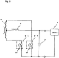
- Figure 8 is a circuit diagram illustrating an example of a power source circuit having a conventional power module.
- the power source circuit is a circuit in which an alternating-current voltage supplied from the primary side positioned to the left of the transformer 4 is converted into a direct-current voltage by two power modules 5-1 and 5-2 on the secondary side positioned on the right, by alternately performing ON/OFF switching processes, so as to charge a battery 1 via a choke coil 3 and a capacitor 2.
- a MOSFET 5a serving as a switching-purpose power semiconductor device is installed.
- Patent Literature 1 describes a method for detecting deteriorations of solder joint parts by detecting degradation in thermal resistance on the basis of changes in a current value that are observed when a forward current is caused to flow through the power semiconductor device.
- Patent Literature 2 describes a method for keeping the temperature at joint parts of a semiconductor device equal to or lower than a tolerance value even when a large current flows therethrough, by using a wide band gap semiconductor as a power semiconductor device.
- another measure is also taken where, for example, a fuse for the purpose of preventing an overcurrent is inserted in the supply path to the battery 1.
- the conventional power module e.g., the power module 5-1 or 5-2
- the conventional power module has the following problems (a) to (c) :
- a power module of the present invention is structured so that a package houses therein: a power semiconductor device used for a switching purpose to conduct/interrupt a current; a detecting means for detecting an operation state of the power semiconductor device and outputting a detection signal; and a switch for a current-interrupting purpose that is connected in series to the power semiconductor device and is configured to, in response to a control signal generated on a basis of the detection signal, go into a conduction state so as to conduct a current flowing in the power semiconductor device during a normal operation of the power semiconductor device and to go into an interruption state so as to interrupt the current flowing in the power semiconductor device when a short-circuit failure has occurred in the power semiconductor device.
- the power module according to the present invention achieves advantageous effects as described in (i) and (ii) below.
- Figure 1 is a schematic circuit diagram illustrating a power module according to a first embodiment of the present invention.
- a power module 10 has a package 10a that houses therein a power semiconductor device and the like.
- the package 10a is formed by using resin, ceramics, or the like that is highly resistant to heat and is highly electrically insulative.
- the package 10a is provided with a current input terminal 11, a current output terminal 12, a control terminal 13 that receives an input of a switching signal Si1, a control terminal 14 that receives an input of a control signal Si2, and a detection terminal 15 that outputs a current detection signal S15.
- the package 10a houses therein a switching-purpose power semiconductor device (e.g., a MOSFET) 21, a current-interrupting purpose switch (e.g., a MOSFET) 22, and a current detecting means (e.g., a resistor) 23 serving as an example of a detecting means.
- a switching-purpose power semiconductor device e.g., a MOSFET
- a current-interrupting purpose switch e.g., a MOSFET
- a current detecting means e.g., a resistor 23 serving as an example of a detecting means.
- a drain source of the MOSFET 21, a drain source of the MOSFET 22, and the resistor 23 are connected in series between the current input terminal 11 and the current output terminal 12.
- a gate of the MOSFET 21 is connected to the control terminal 13.
- a gate of the MOSFET 22 is also connected to the control terminal 14.
- a connection point between the MOSFET 22 and the resistor 23 is connected to the detection terminal 15.
- the MOSFET 21 has a function of conducting/interrupting the current flowing between the current input terminal 11 and the current output terminal 12, as a result of the connection between the drain and the source thereof being turned on/off by the switching signal Si1 input from the control terminal 13 to the gate.
- the MOSFET 22 has a function of going into a conduction state (an ON state) so as to conduct the current flowing in the MOSFET 21 during normal operations of the MOSFET 21 and a function of going into an interruption state (an OFF state) so as to interrupt the current flowing in the MOSFET 21 when a short-circuit failure has occurred in the MOSFET 21, as a result of the connection between the drain and the source thereof being turned on/off by the control signal Si2 flowing from the control terminal 14 to the gate.
- the resistor 23 From the detection terminal 15 and the current output terminal 12, it is possible to extract the voltage between the two ends of the resistor 23 as the detection signal (e.g., a current detection signal) S15 used for detecting an operation state of the MOSFET 21.
- the extracted current detection signal S15 is supplied to a control circuit (not illustrated) provided on the outside.
- the control signal Si2 is generated by the control circuit and is input to the control terminal 14.
- the resistor 23 has a function as a detecting means (e.g., a current detecting means) for detecting an operation state of the MOSFET 21 and outputting the current detection signal S15.
- the control circuit provided on the outside When having determined that the current detection signal S15 output from between the detection terminal 15 and the current output terminal 12 is within a normal range, the control circuit provided on the outside generates the current-conducting purpose control signal Si2 and inputs the generated control signal Si2 to the control terminal 14.
- the current-conducting purpose control signal Si2 brings the MOSFET 22 into the ON state. While in this state, the MOSFET 21 is turned on or off by the switching signal Si1 input thereto from the control terminal 13, so that the current flowing between the current input terminal 11 and the current output terminal 12 is either conducted or interrupted.
- the control circuit provided on the outside determines that a short-circuit failure has occurred in the MOSFET 21 and generates a current-interrupting purpose control signal Si2, so as to input the generated control signal Si2 to the control terminal 14.
- the MOSFET 22 instantly switches from the ON state into the OFF state, so that the current flowing in the MOSFET 21 is interrupted. As a result, the MOSFET 21 is prevented from having a radical and rapid temperature increase.
- Figure 2 is a schematic circuit diagram of a power source circuit illustrating application example 1 of the power module 10 illustrated in Figure 1 .
- the power source circuit has a positive electrode input terminal 31 and a negative electrode input terminal 32 that receive an input of a direct-current voltage supplied to a battery 30.
- a transformer 35 is connected via a capacitor 33 and a choke coil 34.
- a first power module 10-1 is connected between one of the electrodes of the transformer 35 and the negative electrode input terminal 32.
- a second power module 10-2 is also connected.
- the first and the second power modules 10-1 and 10-2 each have the same configuration as that of the power module 10 illustrated in Figure 1 .
- the current input terminal 11 is connected to one of the electrodes of the transformer 35, while the current output terminal 12 is connected to the negative electrode input terminal 32.
- the current input terminal 11 is connected to the other electrode of the transformer 35, while the current output terminal 12 is connected to the negative electrode input terminal 32.
- the power source circuit configured as described above operates in the following manner: An alternating-current voltage supplied by the primary side positioned to the left of the transformer 35 is converted into a direct-current voltage as a result of the two power modules 10-1 and 10-2 switching on and off alternately on the secondary side positioned to the right of the transformer 35.
- the direct-current voltage is smoothed as being routed through the choke coil 34 and the capacitor 33 and is supplied to the battery 30. As a result, the battery 30 is charged.
- the MOSFET 22 is in the ON state during normal operations of the MOSFET 21, so as to conduct the current flowing in the MOSFET 21.
- the voltage between the two ends of the resistor 23 is extracted from between the detection terminal 15 and the current output terminal 12 by the control circuit (not illustrated) provided on the outside, as the current detection signal S15 for the current flowing in the two MOSFETs 21 and 22.
- the control circuit provided on the outside When having determined that the current detection signal S15 is in a normal range, the control circuit provided on the outside inputs the current-conducting purpose control signal Si2 to the control terminal 14 in the MOSFET 22 so as to bring the MOSFET 22 into the ON state. In contrast, when the current detection signal S15 has increased, and the control circuit provided on the outside determines that a short-circuit failure has occurred in the MOSFET 21, the control circuit inputs the current-interrupting purpose control signal Si2 through the control terminal 14 so as to bring the MOSFET 22 into the OFF state. As a result, when the short-circuit failure has occurred in the MOSFET 21, the current path is instantly blocked, so as to stop an excessive supply of the direct current from the battery 30 and to prevent the MOSFET 21 from having a radical and rapid temperature increase.
- Figure 3 is a schematic circuit diagram of a control-circuit-attached power module illustrating application example 2 of the power module 10 illustrated in Figure 1 .
- the control-circuit-attached power module has an input terminal 41 that receives an input of a switching signal Si1 having a rectangular wave and an output terminal 42.
- the power module 10 illustrated in Figure 1 and a control circuit 50 are connected to the input terminal 41 and the output terminal 42.
- the input terminal 41 is connected to the control terminal 13 of the power module 10
- the output terminal 42 is connected to the control circuit 50 and to the current output terminal 12 of the power module 10.
- the control circuit 50 is externally connected.
- the control circuit 50 is a circuit configured to control operations of the power module 10 from the outside thereof.
- the control circuit 50 is structured as a module by being housed in a package 50a.
- the package 50a is provided with an input terminal 51.
- a lead wire drawn out of the package 50a is connected to the control terminal 14 and the detection terminal 15 of the power module 10 and to the output terminal 42.
- the control circuit 50 has a reference voltage source 52 that outputs a reference voltage Vref, a comparison circuit 53, and a latch circuit 54.
- the negative electrode side is connected to the output terminal 42, while the positive electrode thereof is connected to a second input terminal of the comparison circuit 53.
- a first input terminal of the comparison circuit 53 is connected to the detection terminal 15 of the power module 10.
- the comparison circuit 53 is a circuit configured to output a comparison signal by comparing the levels of the current detection signal S15 input thereto from the first input terminal and the reference voltage Vref input thereto from the second input terminal.
- an input terminal of the latch circuit 54 is connected to the output side of the comparison circuit 53.
- the input terminal 51 is connected to another input terminal of the latch circuit 54. Further, an output terminal of the latch circuit 54 is connected to the control terminal 14 of the power module 10.
- the latch circuit 54 is a circuit configured to latch the comparison signal output from the comparison circuit 53 on the basis of a drive signal input thereto from the input terminal 51, and to output the control signal Si2 to the control terminal 14 of the power module 10 with predetermined timing.
- the control-circuit-attached power module configured as described above operates in the following manner:
- the voltage value of the resistor 23 that is output as the current detection signal S15 from the detection terminal 15 of the power module 10 is input to the comparison circuit 53 so as to be compared with the reference voltage Vref.
- the reference voltage Vref is set to have such a voltage value with which it is possible to judge a voltage occurring in the resistor 23 due to the current from a normal operation of the MOSFET 21 and a voltage occurring due to a current at the time of a short-circuit failure. Accordingly, when the current detection signal S15 is smaller than the reference voltage Vref, the comparison circuit 53 outputs a comparison signal yielding a normal operation to the latch circuit 54. On the contrary, when the current detection signal S15 is larger than the reference voltage Vref, the comparison circuit 53 outputs a comparison signal yielding an interrupting operation to the latch circuit 54.
- the latch circuit 54 While the comparison signal yielding the normal operation is being output from the comparison circuit 53, the latch circuit 54 outputs the control signal Si2 to bring the MOSFET 22 into the ON state, to the control terminal 14. In contrast, once the comparison signal yielding the interrupting operation is output from the comparison circuit 53, the latch circuit 54 outputs the control signal Si2 to bring the MOSFET 22 into the OFF state to the control terminal 14 and maintains this state.
- the externally-connected control circuit 50 configured as described above is also appended to each of the power modules 10-1 and 10-2 illustrated in Figure 2 .
- the externally-connected control circuit 50 is used for each of the plurality of power modules 10-1 and 10-2 being used, it is also acceptable to use a circuit that integrally includes the control circuits corresponding to each of the plurality of power modules 10-1 and 10-2 being used.
- the current value used for determining the occurrence of a short-circuit failure for example, a current value that is two to three times as large as a rated current of the MOSFET 21 may be used as an evaluation criterion.
- a detection voltage corresponding to the current value may be used as the reference voltage Vref.
- the power modules 10 i.e., the power modules 10-1 and 10-2
- a power source circuit including the same achieve advantageous effects (a) to (c) below:
- Figure 4 is a schematic circuit diagram illustrating a power module according to a second embodiment of the present invention. Some of the elements that are the same as those in Figure 1 illustrating the first embodiment will be referred to by using the same reference characters.
- a power module 10A according to the second embodiment is different from the power module 10 according to the first embodiment in that the detection terminal 15 is connected to the connection point between the MOSFET 21 and the MOSFET 22. From the detection terminal 15 and the current output terminal 12, the voltage between the two ends of a circuit including the MOSFET 22 and the resistor 23 is extracted as the current detection signal S15 used for detecting an operation state of the MOSFET 21.
- Operations performed by the power module 10A according to the present embodiment are the same as the operations performed by the power module 10 according to the first embodiment, except that the current detection signal S15 according to the second embodiment is larger than the current detection signal S15 in the power module 10 according to the first embodiment by an amount corresponding to the voltage occurring between the two ends of the MOSFET 22.
- the current detection signal S15 is supplied to a control circuit (not illustrated) provided on the outside.
- the control circuit generates the control signal Si2 and inputs the generated control signal Si2 to the control terminal 14.
- the control circuit provided on the outside When having determined that the current detection signal S15 output thereto from between the detection terminal 15 and the current output terminal 12 is within a normal range, the control circuit provided on the outside generates the current-conducting purpose control signal Si2 and inputs the generated control signal Si2 to the control terminal 14.
- the current-conducting purpose control signal Si2 that has been input brings the MOSFET 22 into the ON state.
- Figure 5 is a schematic circuit diagram illustrating a power module according to a third embodiment of the present invention. Some of the elements that are the same as those in Figure 1 illustrating the first embodiment will be referred to by using the same reference characters.
- a temperature sensing device 24 such as a thermistor serving as a temperature detecting means is provided in place of the resistor 23 included in the power module 10 according to the first embodiment. Further, another detection terminal 16 is newly provided in addition to the detection terminal 15 provided in the power module 10 according to the first embodiment.
- the two detection terminals 15 and 16 are provided for the package 10a.
- the temperature sensing device 24 is connected to a point between the two detection terminals 15 and 16.
- the temperature sensing device 24 is a device that is installed in the vicinity of the MOSFET 21 and is configured to detect a temperature exhibited during operations of the MOSFET 21 and to output a temperature detection signal S24 to the detection terminals 15 and 16.
- a thermistor is used as the temperature sensing device 24, because the resistance value of the thermistor changes in accordance with the temperature, the change in the resistance value may be used as the temperature detection signal S24.
- the temperature of the MOSFET 21 increases.
- the temperature increase is detected by the temperature sensing device 24, and the temperature detection signal S24 is therefore output from the detection terminals 15 and 16.
- the temperature detection signal S24 is supplied, for example, to a control circuit similar to the externally-connected control circuit 50 illustrated in Figure 3 .
- the comparison circuit 53 compares the supplied temperature detection signal S24 with the reference voltage Vref.
- the temperature of the MOSFET 21 during operations thereof is dependent on the type of the MOSFET 21, the structure thereof including a heat radiating plate or the like, the operation conditions thereof, and the like. Further, the detected temperature varies depending on the location in which the temperature sensing device 24 is installed. Accordingly, the reference voltage Vref is set so as to be dependent on the power module 10B subject to the processing. In other words, the reference voltage Vref is set to have such a voltage value with which it is possible to judge the temperature detected during a normal operation of the MOSFET 21 and the temperature detected at the time of a short-circuit failure.
- the comparison circuit 53 When the temperature detection signal S24 is smaller than the reference voltage Vref, the comparison circuit 53 outputs a comparison signal yielding a normal operation. On the contrary, when the temperature detection signal S24 is larger than the reference voltage Vref, the comparison circuit 53 outputs a comparison signal yielding an interrupting operation. While the comparison signal yielding the normal operation is being output from the comparison circuit 53, the latch circuit 54 outputs the control signal Si2 that brings the MOSFET 22 into the ON state. In contrast, once the comparison signal yielding the interrupting operation is output from the comparison circuit 53, the latch circuit 54 outputs the control signal Si2 that brings the MOSFET 22 into the OFF state and maintains this state.
- the power module 10B according to the third embodiment is provided with the temperature sensing device 24 configured to detect the occurrence of a short-circuit failure in the MOSFET 21 at the time of the occurrence. It is therefore possible to instantly block the current path of the MOSFET 21 when a short-circuit failure has occurred. Accordingly, it is possible to prevent the MOSFET 21 from having a radical and rapid temperature increase by blocking any excessive current.
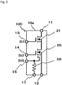
- Figure 6 is a schematic circuit diagram illustrating a power module according to a fourth embodiment of the present invention. Some of the elements that are the same as those in Figure 1 illustrating the first embodiment will be referred to by using the same reference characters.
- a current-interrupting purpose switch MOSFET 25, a resistor 26 serving as a current detecting means, and a current-detecting purpose detection terminal 17 are provided, in place of the MOSFET 22 and the resistor 23 provided in the power module 10 according to the first embodiment.
- the MOSFET 25 is a device obtained by integrating a main switching-purpose MOSFET together with a current-detecting purpose MOSFET (i.e., a so-called sense MOSFET).
- the MOSFET 25 has the current-detecting purpose terminal.
- the detection terminal 15 is connected to the current-detecting purpose terminal of the MOSFET 25.
- the resistor 26 is connected to a point between the detection terminal 15 and the detection terminal 17.
- the MOSFET 25 has a function of going into the ON state so as to conduct the current flowing in the MOSFET 21 during normal operations of the MOSFET 21 and a function of going into the OFF state so as to interrupt the current flowing in the MOSFET 21 when a short-circuit failure has occurred in the MOSFET 21.
- MOSFET 25 is connected in series to the MOSFET 21, a signal corresponding to the current value of MOSFET 25 detected as a voltage value between the two ends of the resistor 26 also corresponds to the current value of the MOSFET 21.
- the power module 10B according to the fourth embodiment is controlled, for example, by a control circuit similar to the externally-connected control circuit 50 illustrated in Figure 3 .
- a short-circuit failure has occurred in the MOSFET 21
- the current in the MOSFET 21 increases.
- the current flowing in the MOSFET 25 also increases, and the detection voltage values detected from the detection terminals 15 and 17 therefore increase.
- the detection voltage values are supplied, for example, to the control circuit similar to the control circuit 50 illustrated in Figure 3 .
- the comparison circuit 53 compares the supplied detection voltage value with the reference voltage Vref.
- the reference voltage Vref is set to have such a voltage value with which it is possible to judge a detection voltage value detected during a normal operation of the MOSFET 21 and a detection voltage value detected at the time of a short-circuit failure.
- the comparison circuit 53 When the detection voltage value is smaller than the reference voltage Vref, the comparison circuit 53 outputs a comparison signal yielding a normal operation. On the contrary, when the detection voltage value is larger than the reference voltage Vref, the comparison circuit 53 outputs a comparison signal yielding an interrupting operation. While the comparison signal yielding the normal operation is being output from the comparison circuit 53, the latch circuit 54 outputs the control signal Si2 that brings the MOSFET 25 into the ON state. In contrast, once the comparison signal yielding the interrupting operation is output from the comparison circuit 53, the latch circuit 54 outputs the control signal Si2 that brings the MOSFET 25 into the OFF state and maintains this state.
- the power module 10B according to the fourth embodiment is configured, when a short-circuit failure has occurred in the MOSFET 21, to detect the occurrence of the short-circuit failure on the basis of the voltage value between the two ends of the resistor 26. Accordingly, it is possible to interrupt any excessive current by causing the MOSFET 25 to instantly block the current path of the MOSFET 21. It is therefore possible to prevent the MOSFET 21 from having a radical and rapid temperature increase.
- Figure 7 is a schematic circuit diagram illustrating a power module according to a fifth embodiment of the present invention. Some of the elements that are the same as those in Figure 3 illustrating the first embodiment will be referred to by using the same reference characters.
- the externally-connected control circuit 50 illustrated in Figure 3 is housed in the package 10a, so as to structure a power module that has the control circuit installed therein.
- the control circuit 50 installed in the package 10a is configured by using, for example, a semiconductor Integrated Circuit (IC) having one or more chips.
- IC semiconductor Integrated Circuit
- the power module 10D having the control circuit installed therein according to the fifth embodiment performs the same operations as those illustrated in Figure 3 according to the first embodiment.
- the power module 10D according to the fifth embodiment achieves the same advantageous effects as those illustrated in Figure 3 according to the first embodiment. Further, because the power module 10D according to the fifth embodiment has the control circuit 50 installed in the package 10a, when the power module 10D is used in a power source circuit or the like, it is not necessary to have an externally-connected control circuit. It is therefore possible to easily apply the power module 10D to various circuits.
- the present invention is not limited to the first to the fifth embodiments described above. Other various modes of use and modifications are also possible.
Landscapes
- Engineering & Computer Science (AREA)
- Power Engineering (AREA)
- Protection Of Static Devices (AREA)
- Power Conversion In General (AREA)
- Rectifiers (AREA)
- Charge And Discharge Circuits For Batteries Or The Like (AREA)
Applications Claiming Priority (1)
| Application Number | Priority Date | Filing Date | Title |
|---|---|---|---|
| PCT/JP2016/061223 WO2017175326A1 (ja) | 2016-04-06 | 2016-04-06 | パワーモジュール |
Publications (2)
| Publication Number | Publication Date |
|---|---|
| EP3442019A1 true EP3442019A1 (de) | 2019-02-13 |
| EP3442019A4 EP3442019A4 (de) | 2019-12-04 |
Family
ID=60000988
Family Applications (1)
| Application Number | Title | Priority Date | Filing Date |
|---|---|---|---|
| EP16892932.1A Withdrawn EP3442019A4 (de) | 2016-04-06 | 2016-04-06 | Leistungsmodul |
Country Status (6)
| Country | Link |
|---|---|
| US (1) | US10770882B2 (de) |
| EP (1) | EP3442019A4 (de) |
| JP (1) | JP6284683B1 (de) |
| CN (1) | CN107466424B (de) |
| TW (1) | TWI681627B (de) |
| WO (1) | WO2017175326A1 (de) |
Families Citing this family (8)
| Publication number | Priority date | Publication date | Assignee | Title |
|---|---|---|---|---|
| EP3343741A4 (de) * | 2015-08-28 | 2018-08-29 | Shindengen Electric Manufacturing Co., Ltd. | Leistungsumwandlungsvorrichtung und halbleiterbauelement |
| FR3075518B1 (fr) * | 2017-12-18 | 2021-01-29 | Safran Electronics & Defense | Circuit de commutation |
| JP7472663B2 (ja) * | 2020-06-05 | 2024-04-23 | 富士電機株式会社 | 電力変換装置 |
| US11929698B2 (en) | 2021-03-23 | 2024-03-12 | Snap-On Incorporated | Short circuit protection for a BLDC motor |
| CN113551796B (zh) * | 2021-07-12 | 2022-04-26 | 珠海格力电器股份有限公司 | 一种桥臂结温检测装置、方法和空调 |
| CN113572462A (zh) * | 2021-09-23 | 2021-10-29 | 深圳市依思普林科技有限公司 | 功率半导体模块 |
| FR3147668B1 (fr) * | 2023-04-05 | 2025-03-07 | Safran Electronics & Defense | Système et méthode de protection d’un système électronique d’actionnement contre un sur-courant |
| US20250364982A1 (en) * | 2024-05-25 | 2025-11-27 | Blue Origin Manufacturing, LLC | Intrinsically powered, tunable, short-circuit detection and protection for silicon carbide field effect transistors |
Family Cites Families (28)
| Publication number | Priority date | Publication date | Assignee | Title |
|---|---|---|---|---|
| JPH0659025B2 (ja) | 1985-09-13 | 1994-08-03 | ロ−ム株式会社 | トランジスタの保護回路 |
| JPH02266712A (ja) | 1989-04-07 | 1990-10-31 | Fuji Electric Co Ltd | 半導体装置 |
| JP2643459B2 (ja) * | 1989-07-06 | 1997-08-20 | 三菱電機株式会社 | パワーデバイスの駆動・保護回路 |
| JPH07115354A (ja) | 1993-10-18 | 1995-05-02 | Fanuc Ltd | インテリジェントパワーモジュール |
| JPH0854427A (ja) | 1994-08-10 | 1996-02-27 | Fuji Electric Co Ltd | 半導体素子の電流検出装置 |
| JP3485655B2 (ja) * | 1994-12-14 | 2004-01-13 | 株式会社ルネサステクノロジ | 複合型mosfet |
| US5563759A (en) * | 1995-04-11 | 1996-10-08 | International Rectifier Corporation | Protected three-pin mosgated power switch with separate input reset signal level |
| JPH1014099A (ja) * | 1996-06-21 | 1998-01-16 | Nec Corp | 過電流検出回路 |
| JP2006352931A (ja) * | 2003-09-10 | 2006-12-28 | Sanken Electric Co Ltd | スイッチング素子保護回路 |
| DE102006006878A1 (de) * | 2006-01-20 | 2007-07-26 | Continental Teves Ag & Co. Ohg | Schaltungsanordnung mit Rückspeiseschutz zum Schalten in Leistungsanwendungen |
| JP2008017557A (ja) | 2006-07-03 | 2008-01-24 | Toshiba Corp | 電力変換装置 |
| JP2008236907A (ja) | 2007-03-20 | 2008-10-02 | Toshiba Mitsubishi-Electric Industrial System Corp | 電力変換装置のゲート制御回路及びゲート制御方法 |
| JP4830993B2 (ja) * | 2007-07-11 | 2011-12-07 | 富士電機株式会社 | 半導体装置の劣化検出方法 |
| DE102008053074A1 (de) * | 2008-07-09 | 2010-01-21 | Siemens Aktiengesellschaft | Schnellschalteinrichtung für eine Hochleistungs-Batterie in einem Gleichstrominselnetz |
| WO2010004738A1 (ja) * | 2008-07-11 | 2010-01-14 | 三菱電機株式会社 | 整流装置およびそれを備えた太陽光発電システム |
| JP2010263730A (ja) * | 2009-05-11 | 2010-11-18 | Funai Electric Co Ltd | Usb電源回路 |
| JP2011010393A (ja) * | 2009-06-23 | 2011-01-13 | Panasonic Electric Works Co Ltd | 直流用分岐回路保護装置 |
| JP4722229B1 (ja) | 2010-01-18 | 2011-07-13 | 三菱電機株式会社 | パワー半導体モジュール、電力変換装置および鉄道車両 |
| US9310819B2 (en) * | 2012-09-07 | 2016-04-12 | Infineon Technologies Americas Corp. | Power converter including integrated driver providing overcurrent protection |
| EP2736170B1 (de) * | 2012-11-23 | 2015-06-17 | Nxp B.V. | Kaskodenhalbleiterbauelemente |
| JP6139130B2 (ja) * | 2012-12-27 | 2017-05-31 | 矢崎総業株式会社 | 電磁誘導負荷の制御装置 |
| CN104112719B (zh) * | 2013-08-22 | 2017-02-08 | 广东美的制冷设备有限公司 | 混合集成电路模块及其制造方法 |
| EP3080845B1 (de) * | 2013-11-15 | 2021-12-22 | Texas Instruments Incorporated | Verfahren und schaltung zum steuern eines abreicherungstransistors |
| WO2015104921A1 (ja) * | 2014-01-09 | 2015-07-16 | 日立オートモティブシステムズ株式会社 | 車載用電子制御装置 |
| TW201530999A (zh) * | 2014-01-17 | 2015-08-01 | Beyond Innovation Tech Co Ltd | 具有過電流與過電壓保護功能的升壓裝置 |
| JP6373702B2 (ja) | 2014-09-26 | 2018-08-15 | 株式会社日立製作所 | 半導体パワーモジュール及び半導体駆動装置 |
| JP6256292B2 (ja) * | 2014-10-22 | 2018-01-10 | 株式会社デンソー | 温度保護装置 |
| IL237775B (en) * | 2015-03-16 | 2019-03-31 | Redler Tech Ltd | Automatic, highly reliable, fully redundant electornic circuit breaker that includes means for preventing short-circuit overcurrent |
-
2016
- 2016-04-06 WO PCT/JP2016/061223 patent/WO2017175326A1/ja not_active Ceased
- 2016-04-06 JP JP2017519343A patent/JP6284683B1/ja active Active
- 2016-04-06 US US15/543,173 patent/US10770882B2/en active Active
- 2016-04-06 EP EP16892932.1A patent/EP3442019A4/de not_active Withdrawn
- 2016-04-06 CN CN201680006905.7A patent/CN107466424B/zh active Active
-
2017
- 2017-03-27 TW TW106110131A patent/TWI681627B/zh active
Also Published As
| Publication number | Publication date |
|---|---|
| EP3442019A4 (de) | 2019-12-04 |
| CN107466424A (zh) | 2017-12-12 |
| JPWO2017175326A1 (ja) | 2018-04-19 |
| TWI681627B (zh) | 2020-01-01 |
| CN107466424B (zh) | 2020-07-17 |
| US20180048141A1 (en) | 2018-02-15 |
| US10770882B2 (en) | 2020-09-08 |
| WO2017175326A1 (ja) | 2017-10-12 |
| JP6284683B1 (ja) | 2018-03-07 |
| TW201737626A (zh) | 2017-10-16 |
Similar Documents
| Publication | Publication Date | Title |
|---|---|---|
| US10770882B2 (en) | Power module | |
| ES2929540T3 (es) | Aparato para la conmutación y protección de una carga | |
| US10044180B2 (en) | Electronic circuit breaker for an electrical load in an on-board electrical system of a motor vehicle | |
| US8810985B2 (en) | Hybrid circuit breaker | |
| US9461533B2 (en) | Electronic circuit | |
| CN105474542B (zh) | 半导体装置 | |
| US10447024B2 (en) | Current circuit breaker | |
| EP2391008B1 (de) | Schutzvorrichtung und Verfahren für elektronische Vorrichtungen | |
| CN104935026B (zh) | 具有电池组电池和限流电路的电池组电池装置和相应方法 | |
| KR101769650B1 (ko) | 게이트 전압 감지를 통한 igbt 고장 확인 회로 | |
| CN101652927A (zh) | 用于负载电路的过电流保护装置 | |
| US12413064B2 (en) | Short-circuit detector for electronic fuse circuit | |
| CN109863569B (zh) | 保护开关器 | |
| US20240291264A1 (en) | Electronic fuse circuit and circuit system using the same | |
| EP2874257A1 (de) | Fehlerstrombegrenzer | |
| US10291221B2 (en) | Control device for a power semiconductor switch | |
| CN113383494B (zh) | 电开关 | |
| US20150116885A1 (en) | Semiconductor device | |
| KR102910252B1 (ko) | 이차전지 단락사고 보호장치 | |
| US11183834B2 (en) | Semiconductor module and power conversion apparatus having a diode bridge circuit and a protection circuit | |
| CN110875587A (zh) | 低压断路器和方法 | |
| KR20150068310A (ko) | 배터리 상태 감시 회로 및 배터리 장치 | |
| CN113039711B (zh) | 用于识别关断电流的方法、电开关和直流电压电网 | |
| EP4576212A1 (de) | Halbleiter-dc-schutzschalter und halbleitermodul | |
| CN110797836B (zh) | 用于电机驱动器中的开关电源的电路、操作方法和电机驱动电路系统 |
Legal Events
| Date | Code | Title | Description |
|---|---|---|---|
| STAA | Information on the status of an ep patent application or granted ep patent |
Free format text: STATUS: UNKNOWN |
|
| STAA | Information on the status of an ep patent application or granted ep patent |
Free format text: STATUS: THE INTERNATIONAL PUBLICATION HAS BEEN MADE |
|
| PUAI | Public reference made under article 153(3) epc to a published international application that has entered the european phase |
Free format text: ORIGINAL CODE: 0009012 |
|
| STAA | Information on the status of an ep patent application or granted ep patent |
Free format text: STATUS: REQUEST FOR EXAMINATION WAS MADE |
|
| 17P | Request for examination filed |
Effective date: 20170913 |
|
| AK | Designated contracting states |
Kind code of ref document: A1 Designated state(s): AL AT BE BG CH CY CZ DE DK EE ES FI FR GB GR HR HU IE IS IT LI LT LU LV MC MK MT NL NO PL PT RO RS SE SI SK SM TR |
|
| AX | Request for extension of the european patent |
Extension state: BA ME |
|
| DAV | Request for validation of the european patent (deleted) | ||
| DAX | Request for extension of the european patent (deleted) | ||
| A4 | Supplementary search report drawn up and despatched |
Effective date: 20191106 |
|
| RIC1 | Information provided on ipc code assigned before grant |
Ipc: H03K 17/10 20060101ALI20191030BHEP Ipc: H02M 7/12 20060101ALI20191030BHEP Ipc: H01L 23/58 20060101AFI20191030BHEP |
|
| STAA | Information on the status of an ep patent application or granted ep patent |
Free format text: STATUS: EXAMINATION IS IN PROGRESS |
|
| 17Q | First examination report despatched |
Effective date: 20210416 |
|
| GRAP | Despatch of communication of intention to grant a patent |
Free format text: ORIGINAL CODE: EPIDOSNIGR1 |
|
| STAA | Information on the status of an ep patent application or granted ep patent |
Free format text: STATUS: GRANT OF PATENT IS INTENDED |
|
| INTG | Intention to grant announced |
Effective date: 20230810 |
|
| STAA | Information on the status of an ep patent application or granted ep patent |
Free format text: STATUS: THE APPLICATION IS DEEMED TO BE WITHDRAWN |
|
| 18D | Application deemed to be withdrawn |
Effective date: 20231221 |