EP3444929A1 - Dispositif de fabrication et procédé de fabrication d'un noyau à aimant incorporé - Google Patents
Dispositif de fabrication et procédé de fabrication d'un noyau à aimant incorporé Download PDFInfo
- Publication number
- EP3444929A1 EP3444929A1 EP17782216.0A EP17782216A EP3444929A1 EP 3444929 A1 EP3444929 A1 EP 3444929A1 EP 17782216 A EP17782216 A EP 17782216A EP 3444929 A1 EP3444929 A1 EP 3444929A1
- Authority
- EP
- European Patent Office
- Prior art keywords
- resin
- magnet
- magnet insertion
- manufacturing
- insertion hole
- Prior art date
- Legal status (The legal status is an assumption and is not a legal conclusion. Google has not performed a legal analysis and makes no representation as to the accuracy of the status listed.)
- Granted
Links
Images




Classifications
-
- H—ELECTRICITY
- H02—GENERATION; CONVERSION OR DISTRIBUTION OF ELECTRIC POWER
- H02K—DYNAMO-ELECTRIC MACHINES
- H02K15/00—Processes or apparatus specially adapted for manufacturing, assembling, maintaining or repairing of dynamo-electric machines
- H02K15/12—Impregnating, moulding insulation, heating or drying of windings, stators, rotors or machines
- H02K15/125—Heating or drying of machines in operational state, e.g. standstill heating
-
- B—PERFORMING OPERATIONS; TRANSPORTING
- B29—WORKING OF PLASTICS; WORKING OF SUBSTANCES IN A PLASTIC STATE IN GENERAL
- B29C—SHAPING OR JOINING OF PLASTICS; SHAPING OF MATERIAL IN A PLASTIC STATE, NOT OTHERWISE PROVIDED FOR; AFTER-TREATMENT OF THE SHAPED PRODUCTS, e.g. REPAIRING
- B29C43/00—Compression moulding, i.e. applying external pressure to flow the moulding material; Apparatus therefor
- B29C43/02—Compression moulding, i.e. applying external pressure to flow the moulding material; Apparatus therefor of articles of definite length, i.e. discrete articles
- B29C43/18—Compression moulding, i.e. applying external pressure to flow the moulding material; Apparatus therefor of articles of definite length, i.e. discrete articles incorporating preformed parts or layers, e.g. compression moulding around inserts or for coating articles
-
- B—PERFORMING OPERATIONS; TRANSPORTING
- B29—WORKING OF PLASTICS; WORKING OF SUBSTANCES IN A PLASTIC STATE IN GENERAL
- B29C—SHAPING OR JOINING OF PLASTICS; SHAPING OF MATERIAL IN A PLASTIC STATE, NOT OTHERWISE PROVIDED FOR; AFTER-TREATMENT OF THE SHAPED PRODUCTS, e.g. REPAIRING
- B29C45/00—Injection moulding, i.e. forcing the required volume of moulding material through a nozzle into a closed mould; Apparatus therefor
- B29C45/03—Injection moulding apparatus
-
- B—PERFORMING OPERATIONS; TRANSPORTING
- B29—WORKING OF PLASTICS; WORKING OF SUBSTANCES IN A PLASTIC STATE IN GENERAL
- B29C—SHAPING OR JOINING OF PLASTICS; SHAPING OF MATERIAL IN A PLASTIC STATE, NOT OTHERWISE PROVIDED FOR; AFTER-TREATMENT OF THE SHAPED PRODUCTS, e.g. REPAIRING
- B29C45/00—Injection moulding, i.e. forcing the required volume of moulding material through a nozzle into a closed mould; Apparatus therefor
- B29C45/14—Injection moulding, i.e. forcing the required volume of moulding material through a nozzle into a closed mould; Apparatus therefor incorporating preformed parts or layers, e.g. injection moulding around inserts or for coating articles
- B29C45/14467—Joining articles or parts of a single article
-
- B—PERFORMING OPERATIONS; TRANSPORTING
- B29—WORKING OF PLASTICS; WORKING OF SUBSTANCES IN A PLASTIC STATE IN GENERAL
- B29C—SHAPING OR JOINING OF PLASTICS; SHAPING OF MATERIAL IN A PLASTIC STATE, NOT OTHERWISE PROVIDED FOR; AFTER-TREATMENT OF THE SHAPED PRODUCTS, e.g. REPAIRING
- B29C45/00—Injection moulding, i.e. forcing the required volume of moulding material through a nozzle into a closed mould; Apparatus therefor
- B29C45/17—Component parts, details or accessories; Auxiliary operations
- B29C45/76—Measuring, controlling or regulating
- B29C45/7653—Measuring, controlling or regulating mould clamping forces
-
- B—PERFORMING OPERATIONS; TRANSPORTING
- B29—WORKING OF PLASTICS; WORKING OF SUBSTANCES IN A PLASTIC STATE IN GENERAL
- B29C—SHAPING OR JOINING OF PLASTICS; SHAPING OF MATERIAL IN A PLASTIC STATE, NOT OTHERWISE PROVIDED FOR; AFTER-TREATMENT OF THE SHAPED PRODUCTS, e.g. REPAIRING
- B29C45/00—Injection moulding, i.e. forcing the required volume of moulding material through a nozzle into a closed mould; Apparatus therefor
- B29C45/17—Component parts, details or accessories; Auxiliary operations
- B29C45/76—Measuring, controlling or regulating
- B29C45/80—Measuring, controlling or regulating of relative position of mould parts
-
- F—MECHANICAL ENGINEERING; LIGHTING; HEATING; WEAPONS; BLASTING
- F16—ENGINEERING ELEMENTS AND UNITS; GENERAL MEASURES FOR PRODUCING AND MAINTAINING EFFECTIVE FUNCTIONING OF MACHINES OR INSTALLATIONS; THERMAL INSULATION IN GENERAL
- F16H—GEARING
- F16H25/00—Gearings comprising primarily only cams, cam-followers and screw-and-nut mechanisms
- F16H25/18—Gearings comprising primarily only cams, cam-followers and screw-and-nut mechanisms for conveying or interconverting oscillating or reciprocating motions
- F16H25/20—Screw mechanisms
-
- H—ELECTRICITY
- H02—GENERATION; CONVERSION OR DISTRIBUTION OF ELECTRIC POWER
- H02K—DYNAMO-ELECTRIC MACHINES
- H02K1/00—Details of the magnetic circuit
- H02K1/06—Details of the magnetic circuit characterised by the shape, form or construction
- H02K1/22—Rotating parts of the magnetic circuit
- H02K1/27—Rotor cores with permanent magnets
- H02K1/2706—Inner rotors
- H02K1/272—Inner rotors the magnetisation axis of the magnets being perpendicular to the rotor axis
- H02K1/274—Inner rotors the magnetisation axis of the magnets being perpendicular to the rotor axis the rotor consisting of two or more circumferentially positioned magnets
- H02K1/2753—Inner rotors the magnetisation axis of the magnets being perpendicular to the rotor axis the rotor consisting of two or more circumferentially positioned magnets the rotor consisting of magnets or groups of magnets arranged with alternating polarity
- H02K1/276—Magnets embedded in the magnetic core, e.g. interior permanent magnets [IPM]
-
- H—ELECTRICITY
- H02—GENERATION; CONVERSION OR DISTRIBUTION OF ELECTRIC POWER
- H02K—DYNAMO-ELECTRIC MACHINES
- H02K1/00—Details of the magnetic circuit
- H02K1/06—Details of the magnetic circuit characterised by the shape, form or construction
- H02K1/22—Rotating parts of the magnetic circuit
- H02K1/28—Means for mounting or fastening rotating magnetic parts on to, or to, the rotor structures
-
- H—ELECTRICITY
- H02—GENERATION; CONVERSION OR DISTRIBUTION OF ELECTRIC POWER
- H02K—DYNAMO-ELECTRIC MACHINES
- H02K11/00—Structural association of dynamo-electric machines with electric components or with devices for shielding, monitoring or protection
- H02K11/20—Structural association of dynamo-electric machines with electric components or with devices for shielding, monitoring or protection for measuring, monitoring, testing, protecting or switching
-
- H—ELECTRICITY
- H02—GENERATION; CONVERSION OR DISTRIBUTION OF ELECTRIC POWER
- H02K—DYNAMO-ELECTRIC MACHINES
- H02K11/00—Structural association of dynamo-electric machines with electric components or with devices for shielding, monitoring or protection
- H02K11/20—Structural association of dynamo-electric machines with electric components or with devices for shielding, monitoring or protection for measuring, monitoring, testing, protecting or switching
- H02K11/21—Devices for sensing speed or position, or actuated thereby
-
- H—ELECTRICITY
- H02—GENERATION; CONVERSION OR DISTRIBUTION OF ELECTRIC POWER
- H02K—DYNAMO-ELECTRIC MACHINES
- H02K11/00—Structural association of dynamo-electric machines with electric components or with devices for shielding, monitoring or protection
- H02K11/30—Structural association with control circuits or drive circuits
-
- H—ELECTRICITY
- H02—GENERATION; CONVERSION OR DISTRIBUTION OF ELECTRIC POWER
- H02K—DYNAMO-ELECTRIC MACHINES
- H02K15/00—Processes or apparatus specially adapted for manufacturing, assembling, maintaining or repairing of dynamo-electric machines
- H02K15/02—Processes or apparatus specially adapted for manufacturing, assembling, maintaining or repairing of dynamo-electric machines of stator or rotor bodies
- H02K15/03—Processes or apparatus specially adapted for manufacturing, assembling, maintaining or repairing of dynamo-electric machines of stator or rotor bodies having permanent magnets
-
- H—ELECTRICITY
- H02—GENERATION; CONVERSION OR DISTRIBUTION OF ELECTRIC POWER
- H02K—DYNAMO-ELECTRIC MACHINES
- H02K15/00—Processes or apparatus specially adapted for manufacturing, assembling, maintaining or repairing of dynamo-electric machines
- H02K15/12—Impregnating, moulding insulation, heating or drying of windings, stators, rotors or machines
-
- H—ELECTRICITY
- H02—GENERATION; CONVERSION OR DISTRIBUTION OF ELECTRIC POWER
- H02K—DYNAMO-ELECTRIC MACHINES
- H02K7/00—Arrangements for handling mechanical energy structurally associated with dynamo-electric machines, e.g. structural association with mechanical driving motors or auxiliary dynamo-electric machines
- H02K7/06—Means for converting reciprocating motion into rotary motion or vice versa
-
- B—PERFORMING OPERATIONS; TRANSPORTING
- B29—WORKING OF PLASTICS; WORKING OF SUBSTANCES IN A PLASTIC STATE IN GENERAL
- B29C—SHAPING OR JOINING OF PLASTICS; SHAPING OF MATERIAL IN A PLASTIC STATE, NOT OTHERWISE PROVIDED FOR; AFTER-TREATMENT OF THE SHAPED PRODUCTS, e.g. REPAIRING
- B29C43/00—Compression moulding, i.e. applying external pressure to flow the moulding material; Apparatus therefor
- B29C43/02—Compression moulding, i.e. applying external pressure to flow the moulding material; Apparatus therefor of articles of definite length, i.e. discrete articles
- B29C43/18—Compression moulding, i.e. applying external pressure to flow the moulding material; Apparatus therefor of articles of definite length, i.e. discrete articles incorporating preformed parts or layers, e.g. compression moulding around inserts or for coating articles
- B29C2043/181—Compression moulding, i.e. applying external pressure to flow the moulding material; Apparatus therefor of articles of definite length, i.e. discrete articles incorporating preformed parts or layers, e.g. compression moulding around inserts or for coating articles encapsulated
- B29C2043/182—Compression moulding, i.e. applying external pressure to flow the moulding material; Apparatus therefor of articles of definite length, i.e. discrete articles incorporating preformed parts or layers, e.g. compression moulding around inserts or for coating articles encapsulated completely
-
- B—PERFORMING OPERATIONS; TRANSPORTING
- B29—WORKING OF PLASTICS; WORKING OF SUBSTANCES IN A PLASTIC STATE IN GENERAL
- B29C—SHAPING OR JOINING OF PLASTICS; SHAPING OF MATERIAL IN A PLASTIC STATE, NOT OTHERWISE PROVIDED FOR; AFTER-TREATMENT OF THE SHAPED PRODUCTS, e.g. REPAIRING
- B29C2945/00—Indexing scheme relating to injection moulding, i.e. forcing the required volume of moulding material through a nozzle into a closed mould
- B29C2945/76—Measuring, controlling or regulating
- B29C2945/76003—Measured parameter
- B29C2945/76006—Pressure
-
- B—PERFORMING OPERATIONS; TRANSPORTING
- B29—WORKING OF PLASTICS; WORKING OF SUBSTANCES IN A PLASTIC STATE IN GENERAL
- B29C—SHAPING OR JOINING OF PLASTICS; SHAPING OF MATERIAL IN A PLASTIC STATE, NOT OTHERWISE PROVIDED FOR; AFTER-TREATMENT OF THE SHAPED PRODUCTS, e.g. REPAIRING
- B29C2945/00—Indexing scheme relating to injection moulding, i.e. forcing the required volume of moulding material through a nozzle into a closed mould
- B29C2945/76—Measuring, controlling or regulating
- B29C2945/76003—Measured parameter
- B29C2945/76083—Position
-
- B—PERFORMING OPERATIONS; TRANSPORTING
- B29—WORKING OF PLASTICS; WORKING OF SUBSTANCES IN A PLASTIC STATE IN GENERAL
- B29C—SHAPING OR JOINING OF PLASTICS; SHAPING OF MATERIAL IN A PLASTIC STATE, NOT OTHERWISE PROVIDED FOR; AFTER-TREATMENT OF THE SHAPED PRODUCTS, e.g. REPAIRING
- B29C2945/00—Indexing scheme relating to injection moulding, i.e. forcing the required volume of moulding material through a nozzle into a closed mould
- B29C2945/76—Measuring, controlling or regulating
- B29C2945/76494—Controlled parameter
- B29C2945/76568—Position
-
- B—PERFORMING OPERATIONS; TRANSPORTING
- B29—WORKING OF PLASTICS; WORKING OF SUBSTANCES IN A PLASTIC STATE IN GENERAL
- B29K—INDEXING SCHEME ASSOCIATED WITH SUBCLASSES B29B, B29C OR B29D, RELATING TO MOULDING MATERIALS OR TO MATERIALS FOR MOULDS, REINFORCEMENTS, FILLERS OR PREFORMED PARTS, e.g. INSERTS
- B29K2101/00—Use of unspecified macromolecular compounds as moulding material
- B29K2101/10—Thermosetting resins
-
- B—PERFORMING OPERATIONS; TRANSPORTING
- B29—WORKING OF PLASTICS; WORKING OF SUBSTANCES IN A PLASTIC STATE IN GENERAL
- B29K—INDEXING SCHEME ASSOCIATED WITH SUBCLASSES B29B, B29C OR B29D, RELATING TO MOULDING MATERIALS OR TO MATERIALS FOR MOULDS, REINFORCEMENTS, FILLERS OR PREFORMED PARTS, e.g. INSERTS
- B29K2105/00—Condition, form or state of moulded material or of the material to be shaped
- B29K2105/25—Solid
- B29K2105/251—Particles, powder or granules
-
- B—PERFORMING OPERATIONS; TRANSPORTING
- B29—WORKING OF PLASTICS; WORKING OF SUBSTANCES IN A PLASTIC STATE IN GENERAL
- B29K—INDEXING SCHEME ASSOCIATED WITH SUBCLASSES B29B, B29C OR B29D, RELATING TO MOULDING MATERIALS OR TO MATERIALS FOR MOULDS, REINFORCEMENTS, FILLERS OR PREFORMED PARTS, e.g. INSERTS
- B29K2995/00—Properties of moulding materials, reinforcements, fillers, preformed parts or moulds
- B29K2995/0003—Properties of moulding materials, reinforcements, fillers, preformed parts or moulds having particular electrical or magnetic properties, e.g. piezoelectric
- B29K2995/0008—Magnetic or paramagnetic
-
- B—PERFORMING OPERATIONS; TRANSPORTING
- B29—WORKING OF PLASTICS; WORKING OF SUBSTANCES IN A PLASTIC STATE IN GENERAL
- B29L—INDEXING SCHEME ASSOCIATED WITH SUBCLASS B29C, RELATING TO PARTICULAR ARTICLES
- B29L2031/00—Other particular articles
- B29L2031/748—Machines or parts thereof not otherwise provided for
- B29L2031/7498—Rotors
-
- F—MECHANICAL ENGINEERING; LIGHTING; HEATING; WEAPONS; BLASTING
- F16—ENGINEERING ELEMENTS AND UNITS; GENERAL MEASURES FOR PRODUCING AND MAINTAINING EFFECTIVE FUNCTIONING OF MACHINES OR INSTALLATIONS; THERMAL INSULATION IN GENERAL
- F16H—GEARING
- F16H25/00—Gearings comprising primarily only cams, cam-followers and screw-and-nut mechanisms
- F16H25/18—Gearings comprising primarily only cams, cam-followers and screw-and-nut mechanisms for conveying or interconverting oscillating or reciprocating motions
- F16H25/20—Screw mechanisms
- F16H2025/2053—Screws in parallel arrangement driven simultaneously with an output member moved by the screws
Definitions
- the present invention relates to a method and a device for manufacturing a magnet embedded core having magnets embedded therein.
- Patent Document 1 JP2014-79056A
- the present invention was made in view of such a problem of the prior art, and has a primary object to prevent creation of such unnecessary resin from the resin material used for fixing magnets.
- One embodiment of the present invention provides a device for manufacturing a magnet embedded core including a magnet embedded in resin filling a magnet insertion hole extending axially in a motor core, the device comprising: a resin charging device configured to charge the resin in solid form into the magnet insertion hole; a magnet insertion device configured to insert the magnet into the magnet insertion hole; and a heating device configured to heat the motor core to melt the resin in solid form in the magnet insertion hole.
- the device for manufacturing a magnet embedded core further comprises a pressurization device configured to pressurize the molten resin in the magnet insertion hole.
- the voids that may remain in the molten resin are expelled or contracted so that the magnet can be fixed by the resin relatively free of voids in a reliable manner.
- the manufacturing device further comprises an upper die and a lower die configured to clamp the motor core between the upper die and the lower die.
- the motor core can be clamped between the upper die and the lower die.
- the manufacturing device further comprises a pressurization device configured to pressurize the molten resin in the magnet insertion hole via the upper die and the lower die.
- the pressurization step can be performed in a reliable manner, and the magnet can be fixed by the resin relatively free of voids in an even more reliable manner.
- the resin charging device is configured to charge the resin into the magnet insertion hole in the motor core placed on the lower die.
- the resin charging device is configured to charge the resin into the magnet insertion hole in the motor core outside the upper die and the lower die.
- the magnet insertion device is configured to insert the magnet into the magnet insertion hole in the motor core placed on the lower die.
- the magnet insertion device is configured to insert the magnet into the magnet insertion hole in the motor core outside the upper die and the lower die.
- this manufacturing device further comprises a heating oven configured to heat the motor core outside the upper die and the lower die.
- Another aspect of the present invention provides a method for manufacturing a magnet embedded core including a magnet embedded in resin filling a magnet insertion hole extending axially in a motor core, the method comprising: a resin charging step of charging the resin in solid form into the magnet insertion hole; a magnet insertion step of inserting the magnet before or after the resin charging step; a melting step of melting the resin in the magnet insertion hole; and a curing step of curing the molten resin.
- the manufacturing method further comprises a resin pressurization step of pressurizing the molten resin.
- the voids that may remain in the molten resin are expelled or contracted so that the magnet can be fixed by the resin relatively free of voids in a reliable manner.
- the melting step comprises at least partly melting the solid resin by the motor core which is preheated prior to the resin charging step.
- the time period required for the motor core to reach a temperature required for melting the solid thermosetting resin in the melting step can be reduced so that the manufacturing efficiency can be improved.
- the solid resin is formed by molding uncured raw material resin in powder or granular form into a prescribed shape.
- the solid resin molded into the prescribed shape may include the solid resin molded to conform to the shape of the magnet insertion hole.
- the amount of the solid resin that is to be charged into the magnet insertion hole can be set to a correct amount beforehand. Also, the handling of the solid resin can be improved, and the work efficiency in the resin charging step can be improved.
- At least one of outer surfaces of the solid resin is in contact with an inner surface of the motor core defining the magnet insertion hole.
- the heat transfer from the motor core to the solid resin is performed in an efficient manner so that the time period required for melting the solid resin in the magnet insertion hole can be reduced, and the manufacturing efficiency can be improved.
- the solid resin is in uncured, granular form.
- the solid resin in uncured, granular form may include tablets.
- the solid resin can be charged into the magnet insertion hole both correctly and easily.
- the magnet may be preheated before being inserted into the magnet insertion hole.
- the heat of the magnet inserted into the magnet insertion hole effectively contributes to the melting of the solid resin so that the time period required for melting the solid resin in the melting step can be reduced, and the manufacturing efficiency can be improved.
- the device and the method for manufacturing a magnet embedded core according to the present invention can prevent the creation of unnecessary resin from the resin used for fixing the magnet.
- the magnet embedded core 100 has a motor core 101 including a plurality of magnet insertion holes 104, and magnets 110 positioned in the respective magnet insertion holes 104.
- the motor core 101 is formed by stacking a plurality of iron core laminates 106 each formed by punching and consisting of a disk formed with openings for defining a center hole 102 and the magnet insertion holes 104.
- the magnet insertion holes 104 are arranged around the center hole 102, and are each provided with a substantially rectangular shape in plan view (shape of cross section). Each magnet insertion hole 104 extends axially through the motor core 101 in the stacking direction (axial direction), and defines a substantially rectangular space having an upper opening 105 on an upper end surface 108 of the motor core 101. Each magnet insertion hole 104 is passed axially through the motor core 101 in the illustrated embodiment, but may also be provided with a closed bottom by omitting the opening for defining the magnet insertion hole 104 in the lowermost iron core laminate 106.
- Each magnet 110 has a substantially rectangular parallelepiped shape, and is fixed in position relative to the motor core 101 by resin 112 filled in the magnet insertion hole 104.
- the resin 112 may consist of a thermosetting resin such as epoxy resin that can be cured by being heated to a temperature higher than a prescribed curing temperature.
- Each magnet 110 may consist of, for example, a ferrite-based sintered magnet or a permanent magnet (with or without magnetization) such as a neodymium magnet.
- the axial length of each magnet 110 is smaller than the axial length of the magnet insertion hole 104, and the end surface (in this case, the upper surface) of the magnet 110 is covered with the resin 112.
- each magnet 110 is smaller than the width (the dimensions in the tangential direction of the motor core 101 and the radial direction of the motor core 101) of the magnet insertion hole 104.
- the magnet 110 is inwardly offset (or offset toward the center of the motor core 101) in the magnet insertion hole 104 so that the inwardly facing surface 110A of the magnet 110 makes a surface contact with (abuts against) the inner surface 104A of the magnet insertion hole 104.
- each surface defining the magnet insertion hole 104 (excluding the inner surface 104A) and the corresponding side surface of the magnet 110 (excluding the inwardly facing surface 110A) is shown greater than the practical size. It is to be noted that the magnet 110 may be placed in the magnet insertion hole 104 so as to be offset outwardly.
- a manufacturing device for the magnet embedded core of the illustrated embodiment is described in the following with reference to Figures 3 to 9 .
- the manufacturing device of the illustrated embodiment includes a device main body 1.
- the device main body 1 includes a plurality of tie bars 14, a flat lower fixed platen 10 fixed to the lower ends of the tie bars 14, a flat upper fixed platen 12 fixed to the upper ends of the tie bars 14, and a movable platen 16 engaged by the tie bars 14 slidably in an axial direction (vertical direction) so as to be movable in the vertical direction between the lower fixed platen 10 and the upper fixed platen 12.
- the lower fixed platen 10, the upper fixed platen 12, and the movable platen 16 squarely oppose one another.
- a lower die 18 forming a fixed die is attached to the upper surface 11 of the lower fixed platen 10.
- An upper die 20 forming a movable die is attached to the lower surface 17 of the movable platen 16.
- the lower die 18 consists of a flat plate that has an upper surface 19 supporting a conveying tray 21, the conveying tray 21 being conveyed into and out of this position by a conveying device (not shown in the drawings) such as a robot arm.
- the conveying tray 21 consists of a flat plate, and a number of such conveying trays 21 are provided for the single device main body 1 so that a motor core 101 is placed (preset) on each conveying tray 21 outside the device main body 1 (another place outside the lower die 18 and the upper die 20).
- each motor core 101 is correctly positioned on the corresponding conveying tray 21 with the aid of a positioning member (not shown in the drawings) provided on the conveying tray 21.
- a cylindrical heating device 70 is detachably arranged on the outer periphery of the motor core 101.
- the heating device 70 may consist of a high-frequency induction heating device or the like.
- the upper die 20 is provided with a substantially flat lower surface 22 which opposes a substantially flat upper end surface 108 of the motor core 101 placed on the lower die 18 so that the motor core 101 can be pressurized in the lamination direction (in the downward direction) by lowering the movable platen 16.
- the lower surface 22 is provided with pressurization projections 24 in parts thereof aligning with the respective magnet insertion holes 104.
- Each pressurization projection 24 is provided with a rectangular shape in plan view which is conformal to the shape of the magnet insertion hole 104 in plan view.
- the pressurization projections 24 close the upper openings 105 of the magnet insertion holes 104, and pressurize the molten resin 116 in each magnet insertion hole 104.
- the pressurization projections 24 may also consist of members separate from the upper die 20 and be resiliently supported by springs or the like so as to be vertically movable relative to the upper die 20.
- a clamping device (pressurization device) 30 including a toggle link mechanism 42 is provided between the upper fixed platen 12 and the movable platen 16.
- the toggle link mechanism 42 is configured to drive the movable platen 16 toward and away from the lower fixed platen 10 (in the vertical direction), and includes an upper link 34 having one end pivotally connected to a lower part of the upper fixed platen 12 via a pivot shaft 32, and a lower link 38 having one end pivotally connected to an upper part of the movable platen 16 via a pivot shaft 36.
- the other ends of the upper link 34 and the lower link 38 are pivotally connected to each other via a pivot shaft 40.
- the clamping device 30 includes a hydraulic cylinder device 46.
- the hydraulic cylinder device 46 is configured to drive the toggle link mechanism 42, and includes a cylinder tube 47 having a base end pivotally connected to a fixed frame 3 of the device main body 1 via a pivot shaft 44 and a piston rod 48 projecting outwardly from a free end of the cylinder tube 47.
- a tip end of the piston rod 48 is pivotally connected to the other ends of the upper link 34 and the lower link 38 via the pivot shaft 40.
- the die clamping device 30 causes the movable platen 16 to be positioned at the uppermost position (die open position) when the piston rod 48 has retreated and the toggle link mechanism 42 is in the maximally folded state as shown in Figure 3 , and causes the movable platen 16 to be positioned at the lowermost position (die close position) when the piston rod 48 has advanced and the toggle link mechanism 42 is in the maximally extended state as shown in Figure 9 .
- the angle formed between the upper link 34 and the lower link 38 is minimized.
- the maximally extended state can be detected by measuring the vertical position of the movable platen 16 with a linear sensor (not shown) or any other per se known method.
- the upper die 20 is located at the lowermost position together with the movable platen 16, and the lower surface 22 of the upper die 20 is in surface contact with the upper end surface 108 of the motor core 101 placed on the lower die 18 so that the motor core 101 is pressurized in the stacking direction, and the pressurization projections 24 engage the respective magnet insertion holes 104 to close the upper openings 105 thereof and pressurize the molten resin 116 in the respective magnet insertion holes 104.
- This state is referred to as a clamped state (pressurized state).
- Upper ends of a plurality of tubular members 60 extending axially toward the lower die 18 and having closed bottom ends are fixed to the upper die 20.
- the tubular members 60 are arranged around the center of the motor core 101 positioned on the prescribed position of the lower die 18 via the conveying tray 21, and each receive a piston 62 in a vertically slidable manner.
- Each piston 62 has a tip end portion 66 that projects out of the corresponding tubular member 60 via a through hole 64 formed in the bottom wall (lower end) of the tubular member 60.
- a tip end surface 67 of each tip end portion 66 squarely opposes the upper surface 19 of the lower die 18.
- each tubular member 60 a compression coil spring 68 is provided between the upper die 20 and the piston 62.
- Each compression coil spring 68 urges the corresponding piston 62 toward the bottom end of the tubular member 60 or, in other words, toward the side of the lower die 18.
- the urging forces applied to the pistons 62 by the compression coil springs 68 in the respective tubular members 60 may be equal to one another.
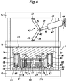
- the tip end surfaces 67 of the pistons 62 are positioned (by appropriately dimensioning the associated component parts) so as to simultaneously come into contact with the upper surface 19 of the lower die 18 as the upper die 20 approaches the lower die 18 or, more specifically, when the upper die 20 descends to a point slightly short of a position where the lower surface 22 of the upper die 20 comes into surface contact with the upper end surface 108 of the motor core 101, as shown in Figure 8 .
- the manufacturing device of this embodiment includes a resin charging device 80 (see Figure 4 ) and a magnet insertion device 90 (see Figure 5 ).
- the resin charging device 80 includes a substrate 82, a plurality of resin holding members 86 provided on the substrate 82 and defining resin holding holes 84, respectively, corresponding to the respective magnet insertion holes 104, and a shutter plate 88 that is rotatably attached to the lower bottom surface of the substrate 82 to selectively shield the lower end openings of the resin holding holes 84.
- a conveying device such as a robot arm or the like, the resin charging device 80 is placed on the upper end surface 108 of the motor core 101 on the lower die 18.
- the resin holding holes 84 are each configured to hold the resin 114 in solid form (hereinafter, solid resin 114).
- the solid resin (resin block) 114 is obtained by molding uncured material resin in powder or granular form into a substantially rectangular parallelepiped shape that matches the shape of the magnet insertion hole 104 by using a tabletting machine or the like (not shown in the drawings) in a preliminary molding process.
- the magnet insertion device 90 includes a substrate 92, a plurality of magnet holding members 96 provided on the substrate 92 and defining magnet holding holes 94, respectively, corresponding to the respective magnet insertion holes 104, and a shutter plate 98 that is rotatably attached to the lower bottom surface of the substrate 92 to selectively shield the lower end openings of the magnet holding holes 94.
- a conveying device such as a robot arm or the like, the magnet insertion device 90 is placed on the upper end surface 108 of the motor core 101 on the lower die 18.
- the resin charging device 80 in which solid resin 114 is placed in each resin holding hole 84, is moved onto the upper end surface 108 of the motor core 101 by using a conveying device (not shown in the drawings). Thereafter, the lower end openings of the resin holding holes 84 are opened by the rotation of the shutter plate 88 with the result that the solid resin 114 in each resin holding hole 84 falls and is thereby charged into the corresponding magnet insertion hole 104.
- the resin charging device 80 is removed from the lower die 18 (carried out to the outside of the device main body 1) by a conveying device (not shown in the drawings).
- each solid resin 114 disposed in each magnet insertion hole 104 is heated within each magnet insertion hole 104 by the heat transferred from the motor core 101 which is heated by the heating device 70. As a result, each solid resin 114 starts melting in the magnet insertion hole 104.
- each piece of the solid resin 114 has at least one outer surface, or outer surfaces 114A and 114B in the illustrated embodiment which are in surface contact with the inner surfaces 104A and 104B of the corresponding magnet insertion hole 104.
- the heat transfer from the motor core 101 to each piece of solid resin 114 is efficiently performed as compared with the case where there is a gap between the two so that the heating of the solid resin 114 in each magnet insertion hole 104 can be performed rapidly and in a thermally efficient manner.
- the magnet insertion device 90 having the magnets 110 received in the respective magnet holding holes 94 is conveyed onto the upper end surface 108 of the motor core on the lower die 18 by using a conveying device (not shown in the drawings). Thereafter, the lower end openings of the magnet holding holes 94 are opened by the rotation of the shutter plate 98, and the magnets 110 in the respective magnet holding holes 94 fall and are thereby inserted into the corresponding magnet insertion holes 104.
- each magnet 110 is performed, with one of the outer surfaces 110A of the magnet 110 being brought into contact with the inner surface 104A of the corresponding magnet insertion hole 104 on the side of the center hole 102, until the lower end surface of the magnet 110 abuts against the upper surface of the solid resin 114 received in the magnet insertion hole 104.
- the magnet insertion device 90 is removed from the lower die 18 (conveyed out to the outside of the device main body 1) by a conveying device (not shown in the drawings).
- the magnets 110 to be inserted into the magnet insertion holes 104 may be heated in advance (preheated) to a predetermined temperature by using a heating oven (not shown in the drawings) or the like.
- the solid resin 114 in each magnet insertion hole 104 is directly heated by the heat of the corresponding magnet 110 in addition to being heated by the heat from the motor core 101 which is heated by the heating device 70.
- Melting of the solid resin 114 means that the raw material resin constituting the solid resin 114 is brought to a liquid state or softened to have a certain fluidity.
- each magnet 110 is pushed toward the bottom of the magnet insertion hole 104.
- the liquid level of the molten resin 116 gradually rises in the magnet insertion hole 104 as the magnet 110 is pushed down further.
- the piston rod 48 is caused to move forward by supplying a hydraulic pressure to the hydraulic cylinder device 46.
- the angle formed by the upper link 34 and the lower link 38 increases, and the toggle link mechanism 42 becomes progressively extended so that the upper die 20 moves downward along with the movable platen 16.
- the toggle link mechanism 42 As the toggle link mechanism 42 further extends, and the upper link 34 and the lower link 38 extend in a straight line as shown in Figure 9 (or, in other words, the toggle link mechanism 42 has fully extended), the lower surface 22 of the upper die 20 comes into surface contact with the upper end surface 108 of the motor core 101 to pressurize the motor core 101 in the stacking direction, and the pressurization projections 24 engage the corresponding magnet insertion holes 104 to close the upper openings 105 and to pressurize the molten resin 116 in the magnet insertion holes 104 as a resin pressurization step (clamped and pressurized state).
- the motor core 101 While in this clamped state, as a curing step, the motor core 101 is heated to a higher temperature than the temperature in the melting step by the heating device 70. As a result, the molten resin 116 is further heated by the heat from the motor core 101 so that the molten resin 116 chemically reacts, and cures irreversibly.
- the magnets 110 in the magnet insertion holes 104 are thereby fixed to the motor core 101 by the cured resin 112 (see Figure 2 ), and the magnet embedded core 100 is completed.
- the completed magnet embedded core 100 is conveyed out of the device main body 1 together with the conveying tray 21 by a conveying device (not shown in the drawings).
- the resin 112 fixes the magnets 110 with a slight or no leakage of the resin 112 into the gaps between the adjacent iron core laminates 106. Thereby, the magnet embedded core 100 having a stable quality with excellent magnetic property can be obtained.
- the curing process is performed while the resin 112 in the magnet insertion holes 104 is pressurized by the pressurization projections 24 as a resin pressurization step, voids that may be remaining in the molten resin 116 are expelled or contracted in a favorable manner before the molten resin 116 is fully cured so that the magnets 110 can be fixed in a reliable manner by the resin 112 having few voids therein.
- the solid resin 114 As the resin 112 used for fixing the magnets 110, the solid resin 114 is charged into the magnet insertion holes 104, and the solid resin 114 is melted in the magnet insertion holes 104. Therefore, as opposed to the injection molding process in which the molten resin is filled into the magnet insertion holes 104 under pressure via runners and gates formed in the die assembly, wastage of the resin remaining in the runners and the gates can be avoided, and the material cost is reduced. Also, by using the solid resin 114, the amount of the solid resin 114 to be charged into the magnet insertion holes 104 can be correctly set without any excess or shortage, and the handling of the material resin can be improved so that the work efficiency of the resin charging step can be improved.
- the compression coil springs 68 are compressed by the downward movement of the upper die 20, along with the tubular member 60, relative to the pistons 62, and provide a spring force that urges the lower die 18 and the upper die 20 away from each other.
- the pressurizing force acting on the motor core 101 is reduced by the sum of the spring forces provided by the compressive deformation of the compression coil springs 68. Namely, the clamping force provided by the toggle link mechanism 42 is partially canceled, and the pressurizing force acting upon the motor core 101 in the stacking direction is reduced from the rated clamping force provided by the toggle link mechanism 42 in the most extended state.
- the leakage of the molten resin 116 to the outside of the magnet insertion holes 104 can be avoided, and the shape precision and the dimensional precision of the motor core 101 can be ensured at the same time. Therefore, the magnet embedded core 100 having a stable quality can be efficiently manufactured.
- the pressurizing force that actually acts on the motor core 101 at the time of clamping the die assembly or when the toggle link mechanism 42 is maximally extended depends on the rated clamping force of the clamping device 30 and the spring properties such as the spring constant, the compressive deformation and the preload of the compression coil springs 68. Therefore, the actual pressurizing force acting upon the motor core 101 when the die assembly is closed can be freely adjusted by changing the spring properties. Therefore, even though the rated clamping force of the clamping device 30 is a fixed value, the pressurizing force actually applied to the motor core 101 when the die assembly is closed can be freely selected.
- the proper pressurizing force when filling the magnet embedded core 100 with the resin varies depending on specifications such as the size of the motor core 101 and the number of the iron core laminates.
- filling of the resin for a wide range of magnet embedded cores 100 with varying specifications can be performed with an optimum pressurizing force for each of the wide range of magnet embedded cores 100 simply by changing the spring properties of the compression coil springs 68 even though the same device main body 1, lower die 18 and upper die 20 are used. Therefore, the investment for the manufacturing device for filling resin for a wide range of magnet embedded cores 100 can be reduced. In other words, with a minimum investment in the manufacturing device, the manufacturing device can be easily adapted to the process of filling resin for a wide range of magnet embedded cores 100.
- the compression coil springs 68 are arranged around the center of the center hole 102 of the motor core 101 positioned on the lower die 18 via the conveying tray 21, the partial canceling of the clamping force of the toggle link mechanism 42 by the spring force of the compression coil springs 68 is prevented from becoming uneven around the center of the motor core 101.
- the pressurizing force acting on the motor core 101 in the stacking direction in the fully clamped state is prevented from becoming uneven around the center of the motor core 101 owing to the compression coil springs 68 so that undesired distortion of the motor core 101 can be avoided.
- each compression coil spring 68 is guided by the corresponding tubular member 60 without undergoing a bending deformation.
- the compression coil spring 68 may be provided with a relatively short length without regard to the opening stroke of the die assembly.
- the lower die 18 is fixed to the lower fixed platen 10 while the upper die 20 is fixed to the movable platen 16, and the compression coil springs 68 are arranged in parallel to one another between the lower die 18 and the upper die 20 so that the spring force of the compression coil springs 68 acts directly upon the lower die 18 and the upper die 20.
- the lower die 18 and the upper die 20 are not supported by or suspended from the lower fixed platen 10 or the movable platen 16 via the compression coil springs 68 in a floating manner. Therefore, the lower die 18 and the upper die 20 are prevented from tilting or otherwise becoming unstable. Owing to such arrangements, a proper clamping action can be ensured at all times.
- the resin charging device 80 is placed on the motor core 101 mounted on the conveying tray 21 at a location outside of the device main body 1 including the lower die 18 and the upper die 20, and charges the solid resin 114 into the magnet insertion holes 104 of the motor core 101.
- the time period during which the device main body 1 is occupied by the resin charging step is eliminated so that the operation efficiency of the device main body 1 is improved. Also, the time period required for manufacturing each magnet embedded core 100 is reduced, and the efficiency of manufacturing the magnet embedded core 100 can be improved.
- the magnet insertion device 90 is placed on the motor core 101 mounted on the conveying tray 21 at a location outside of the device main body 1 including the lower die 18 and the upper die 20, and inserts the magnets 110 into the respective magnet insertion holes 104 of the motor core 101.
- the time period during which the device main body 1 is occupied by the magnet insertion step is eliminated so that the operation efficiency of the device main body 1 is improved. Also, the time period required for manufacturing each magnet embedded core 100 is reduced, and the efficiency of manufacturing the magnet embedded core 100 can be improved.
- a heating oven 120 for heating the motor core 101 is provided separately from the device main body 1 including the lower die 18 and the upper die 20.
- the heating oven 120 has a heater 124 for raising the temperature of the oven interior 122.
- the motor core 101 is heated in the heating oven 120 located outside of the device main body 1. As a result, the motor core 101 is preheated and the time period required to heat the motor core 101 to the temperature necessary for melting the solid resin 114 on the lower die 18 of the device main body 1 is reduced.
- the time period during which the device main body 1 is occupied by the resin melting step is reduced so that the operation efficiency of the device main body 1 is improved. Also, the time period required for manufacturing each magnet embedded core 100 is reduced, and the efficiency of manufacturing the magnet embedded core 100 can be improved.
- uncured granular raw material resin 118 is used as the solid resin.
- the resin holding member 86 of the resin charging device 80 of this embodiment has a funnel shape so that the granular raw material resin 118 can be easily poured therein, and each resin holding member 86 may also serve as a measuring cup for the granular raw material resin 118.
- the magnet insertion step may be performed before the resin charging step.
- the resin since the solid resin is charged into the magnet insertion holes 104 which already contain the magnets 110, from the viewpoint of ease of feeding the resin into the magnet insertion holes 104, the resin preferably consists of uncured granular raw material resin 118.
- the shapes of the magnet insertion holes 104 and the magnets 110 are not limited to a substantially rectangular parallelepiped shape, but may be any other appropriate shape depending on the required magnetic characteristics and other factors.
- the resin 112 is not limited to a thermosetting resin, but may consist of a thermoplastic resin.
- a thermoplastic resin is used as the resin 112
- a curing step by cooling is performed, instead of the thermal curing step for the thermosetting resin.
- the magnet insertion holes 104 are not necessarily required to be through holes each having two open ends, but may also be bottomed holes each opening out at only one end surface of the motor core 101.
- the filling of the resin into the magnet insertion holes 104 may be performed by using solid resin in sheet form or the like, instead of the solid resin 114 in block form or the granular raw material resin 118.
- solid resin since the load in the die opening direction due to the injection pressure of the resin does not act on the die assembly during the resin charging step, the clamping force may be small.
- Pressurization of the motor core 101 at the time of the die clamping step is not necessarily required, and may only be required to the extent necessary for removing voids from the molten resin 116 in the magnet insertion holes 104. Further, the pressurization of the molten resin 116 in the magnet insertion holes 104 may be performed by a separate pressurization device or a pressurizing member, instead of relying on the pressurization projections 24 of the upper die 20.
- the toggle link mechanism 42 may be driven by an electric drive unit using a ball screw and a servomotor, instead of the hydraulic cylinder device 46. In such a case, detection of the maximally extended state of the toggle link mechanism 42 may be detected by any per se known device such as a rotary encoder for detecting the rotational angle of the servomotor. Further, the die clamping device 30 may be driven by a plurality of toggle link mechanisms arranged in parallel to one another.
- the clamping device 30 is not limited to the one using a toggle link mechanism, but may also consist of those directly actuated by hydraulic pressure or an electric motor.
Landscapes
- Engineering & Computer Science (AREA)
- Power Engineering (AREA)
- Manufacturing & Machinery (AREA)
- Mechanical Engineering (AREA)
- Microelectronics & Electronic Packaging (AREA)
- General Engineering & Computer Science (AREA)
- Permanent Field Magnets Of Synchronous Machinery (AREA)
- Manufacture Of Motors, Generators (AREA)
- Manufacturing Cores, Coils, And Magnets (AREA)
- Moulds For Moulding Plastics Or The Like (AREA)
- Iron Core Of Rotating Electric Machines (AREA)
Applications Claiming Priority (4)
| Application Number | Priority Date | Filing Date | Title |
|---|---|---|---|
| PCT/JP2016/002009 WO2017179086A1 (fr) | 2016-04-13 | 2016-04-13 | Procédé de fabrication de noyau à aimant incorporé |
| PCT/JP2016/004123 WO2017179087A1 (fr) | 2016-04-13 | 2016-09-09 | Dispositif et procédé de scellement par résine destinés à un noyau de type à aimant intérieur |
| PCT/JP2016/082291 WO2017179231A1 (fr) | 2016-04-13 | 2016-10-31 | Dispositif et procédé de scellement par résine d'un noyau intégré à un aimant |
| PCT/JP2017/012034 WO2017179398A1 (fr) | 2016-04-13 | 2017-03-24 | Dispositif de fabrication et procédé de fabrication d'un noyau à aimant incorporé |
Publications (3)
| Publication Number | Publication Date |
|---|---|
| EP3444929A1 true EP3444929A1 (fr) | 2019-02-20 |
| EP3444929A4 EP3444929A4 (fr) | 2019-11-27 |
| EP3444929B1 EP3444929B1 (fr) | 2022-08-31 |
Family
ID=60041454
Family Applications (3)
| Application Number | Title | Priority Date | Filing Date |
|---|---|---|---|
| EP16898547.1A Active EP3444927B1 (fr) | 2016-04-13 | 2016-04-13 | Procédé de fabrication d'un corps d'empliment de tôles comprenant des aimants incorporés |
| EP16898548.9A Active EP3444928B1 (fr) | 2016-04-13 | 2016-09-09 | Dispositif et procédé de scellement par résine destinés à un noyau de type à aimant intérieur |
| EP17782216.0A Active EP3444929B1 (fr) | 2016-04-13 | 2017-03-24 | Dispositif de fabrication et procédé de fabrication d'un noyau à aimant incorporé |
Family Applications Before (2)
| Application Number | Title | Priority Date | Filing Date |
|---|---|---|---|
| EP16898547.1A Active EP3444927B1 (fr) | 2016-04-13 | 2016-04-13 | Procédé de fabrication d'un corps d'empliment de tôles comprenant des aimants incorporés |
| EP16898548.9A Active EP3444928B1 (fr) | 2016-04-13 | 2016-09-09 | Dispositif et procédé de scellement par résine destinés à un noyau de type à aimant intérieur |
Country Status (6)
| Country | Link |
|---|---|
| US (3) | US11552540B2 (fr) |
| EP (3) | EP3444927B1 (fr) |
| JP (6) | JP6240365B1 (fr) |
| CN (5) | CN108702068B (fr) |
| MX (3) | MX2018012543A (fr) |
| WO (3) | WO2017179086A1 (fr) |
Families Citing this family (23)
| Publication number | Priority date | Publication date | Assignee | Title |
|---|---|---|---|---|
| EP3444927B1 (fr) * | 2016-04-13 | 2024-04-10 | Kuroda Precision Industries Ltd. | Procédé de fabrication d'un corps d'empliment de tôles comprenant des aimants incorporés |
| CN108908262A (zh) * | 2018-06-13 | 2018-11-30 | 柳州市钜诚科技有限公司 | 一种便于放置模具的模具架 |
| WO2020075275A1 (fr) | 2018-10-11 | 2020-04-16 | 黒田精工株式会社 | Gabarit de support de noyau de rotor, et dispositif et procédé de production de noyau intégré à un aimant |
| US11588384B2 (en) | 2018-11-05 | 2023-02-21 | Kuroda Precision Industries Ltd. | Device and method for manufacturing magnet embedded core |
| CN109286283B (zh) * | 2018-11-06 | 2023-11-14 | 福建省昌辉机电有限公司 | 起动机定子磁铁安装装置 |
| JP7228182B2 (ja) * | 2018-12-17 | 2023-02-24 | Kyb株式会社 | ロータ及びロータの製造方法 |
| CN109603199A (zh) * | 2019-01-09 | 2019-04-12 | 北京精密机电控制设备研究所 | 一种定装原料饮品通用自动化肘结顶紧萃取装置 |
| JP7393347B2 (ja) * | 2019-01-11 | 2023-12-06 | 日本発條株式会社 | ロータの製造方法 |
| JP2020137182A (ja) * | 2019-02-14 | 2020-08-31 | アイシン・エィ・ダブリュ株式会社 | 回転電機用ロータの製造方法 |
| CN109878010B (zh) * | 2019-04-18 | 2024-08-13 | 上海盘毂动力科技股份有限公司 | 一种电机铁芯覆层的制作装置和制作方法 |
| DE102019126763A1 (de) * | 2019-10-04 | 2021-04-08 | Schlaeger Kunststofftechnik Gmbh | Verfahren zur Herstellung eines mit wenigstens einem Bauelement, insbesondere mit einem Funktionselement, versehenen Bauteils |
| JP7444021B2 (ja) * | 2019-10-31 | 2024-03-06 | 株式会社アイシン | ロータの製造装置、及びロータの製造方法 |
| EP3826153A1 (fr) | 2019-11-22 | 2021-05-26 | Siemens Aktiengesellschaft | Entraînement pourvu de boîtier de convertisseur segmenté |
| EP4216411B1 (fr) * | 2019-12-26 | 2026-04-22 | Aisin Corporation | Procédé pour la fabrication d'un rotor |
| JP7414666B2 (ja) * | 2020-08-19 | 2024-01-16 | 株式会社三井ハイテック | コア部製造装置 |
| US11961660B2 (en) * | 2020-08-31 | 2024-04-16 | General Electric Company | Systems and methods for assembling a magnetic-core assembly |
| JP2022129802A (ja) * | 2021-02-25 | 2022-09-06 | 日本電産株式会社 | 回転子製造装置 |
| CN112910202B (zh) * | 2021-03-20 | 2022-08-19 | 广东兰搏科技有限公司 | 一种转子铁芯磁瓦自动装配设备 |
| JP7666988B2 (ja) * | 2021-05-17 | 2025-04-22 | 株式会社三井ハイテック | 鉄心製品の製造方法及び鉄心製品の製造装置 |
| JP7484822B2 (ja) * | 2021-06-09 | 2024-05-16 | 株式会社デンソー | 磁石組付装置 |
| CN113894981A (zh) * | 2021-11-16 | 2022-01-07 | 河北奥赛罗密封材料有限公司 | 一种加芯型高变形密封圈及加芯复合设备 |
| JP7576333B2 (ja) * | 2021-12-06 | 2024-10-31 | アピックヤマダ株式会社 | 樹脂封止装置及び封止金型 |
| CN121128073A (zh) | 2023-06-26 | 2025-12-12 | 株式会社Ihi | 马达的制造方法以及马达 |
Family Cites Families (67)
| Publication number | Priority date | Publication date | Assignee | Title |
|---|---|---|---|---|
| US3488410A (en) | 1966-09-07 | 1970-01-06 | Ace Electronics Associates Inc | Process for molding resistors |
| GB1138435A (en) * | 1967-02-22 | 1969-01-01 | Rolls Royce | Improvements relating to moulding |
| US3568554A (en) | 1967-11-13 | 1971-03-09 | Core Memories Ltd | Magnetic core forming system |
| FR2031719A5 (fr) * | 1969-02-05 | 1970-11-20 | Verre Textile Ste | |
| US4076780A (en) * | 1977-01-27 | 1978-02-28 | General Motors Corporation | Programmable velocity and force control method for compression molding |
| US4204822A (en) * | 1977-08-24 | 1980-05-27 | British Industrial Plastics Ltd. | Moulding machine |
| US4289722A (en) * | 1980-07-28 | 1981-09-15 | General Motors Corporation | Method of potting magnetic speed pickups |
| US4557889A (en) * | 1981-09-26 | 1985-12-10 | Kawasaki Yucoh Co., Ltd. | Method and apparatus for producing sheet molding compound parts by compression |
| US4855097A (en) * | 1983-04-25 | 1989-08-08 | The Budd Company | Compression molding a charge using vacuum |
| JPS60222216A (ja) * | 1984-04-18 | 1985-11-06 | Kawasaki Yukou Kk | 可塑性材料のプレス成形の平衡支持装置 |
| JPS61143240A (ja) * | 1984-12-17 | 1986-06-30 | Inoue Mtp Co Ltd | プラスチツクモ−ルに取付具を固着する方法 |
| US4759280A (en) * | 1986-12-29 | 1988-07-26 | John T. Hepburn, Limited | Hydraulic press with adjustable platen clearance |
| US4923383A (en) | 1987-12-26 | 1990-05-08 | Kabushiki Kaisha Kobe Seiko Sho | Apparatus for mold aligning in a compression molding machine |
| EP0540504B1 (fr) * | 1988-02-29 | 1995-05-31 | Matsushita Electric Industrial Co., Ltd. | Procédé pour fabriquer un article aimant lié à une resine |
| JP2780422B2 (ja) * | 1990-03-07 | 1998-07-30 | 松下電器産業株式会社 | 樹脂磁石構造体の製造方法 |
| US5156782A (en) * | 1991-10-02 | 1992-10-20 | John T. Hepburn, Limited | Maintaining press platens in parallel relationship |
| US5288447A (en) * | 1993-02-22 | 1994-02-22 | General Electric Company | Method of making permanent magnet rotors |
| US5470615A (en) * | 1994-03-11 | 1995-11-28 | Axis Usa, Inc. | Bonding and coating methods and apparatus for th coils of dynamo-electric machine parts |
| GB2345301B (en) * | 1996-09-12 | 2001-01-10 | Prince Corp | Vehicle panel |
| JP3704010B2 (ja) * | 1999-12-07 | 2005-10-05 | 本田技研工業株式会社 | 永久磁石式モータ及び永久磁石固定方法 |
| JP2001352747A (ja) | 2000-06-09 | 2001-12-21 | Aida Eng Ltd | リニアモータおよびこれを駆動源とするプレス成形装置 |
| JP3696071B2 (ja) * | 2000-09-21 | 2005-09-14 | 株式会社ミツバ | 固定金型及び熱硬化性樹脂のランナレス成形方法 |
| JP2002272033A (ja) | 2001-03-13 | 2002-09-20 | Nissan Motor Co Ltd | 永久磁石式同期モータのロータとその製造方法 |
| JP3933040B2 (ja) * | 2002-11-27 | 2007-06-20 | 松下電器産業株式会社 | 希土類ボンド磁石の製造方法とそれを有する永久磁石型モータ |
| JP2005185081A (ja) | 2003-03-05 | 2005-07-07 | Nissan Motor Co Ltd | 回転機用回転子鋼板、回転機用回転子、回転機、およびこれを搭載した車両、ならびに回転機用回転子鋼板の製造装置および製造方法 |
| JP3786946B1 (ja) | 2005-01-24 | 2006-06-21 | 株式会社三井ハイテック | 永久磁石の樹脂封止方法 |
| JP2006211748A (ja) | 2005-01-25 | 2006-08-10 | Mitsui High Tec Inc | 回転子積層鉄心の製造装置及び製造方法 |
| JP2006311782A (ja) * | 2005-03-30 | 2006-11-09 | Toyota Motor Corp | ロータおよびその製造方法 |
| JP4726602B2 (ja) | 2005-10-17 | 2011-07-20 | 株式会社三井ハイテック | 積層鉄心及びその製造方法 |
| CN101356711B (zh) * | 2006-01-11 | 2011-04-27 | 株式会社三井高科技 | 将永磁体树脂密封到叠片转子铁芯中的方法 |
| JP4850528B2 (ja) * | 2006-02-08 | 2012-01-11 | トヨタ自動車株式会社 | ロータの製造方法 |
| JP4853771B2 (ja) | 2006-03-01 | 2012-01-11 | 日立金属株式会社 | ヨーク一体型ボンド磁石およびそれを用いたモータ用磁石回転子 |
| JP2009100634A (ja) | 2007-10-19 | 2009-05-07 | Toyota Motor Corp | 埋込磁石型モータのロータ |
| JP2009171785A (ja) | 2008-01-18 | 2009-07-30 | Toyota Motor Corp | 回転電機 |
| JP2010213536A (ja) * | 2009-03-12 | 2010-09-24 | Asmo Co Ltd | 回転電機ヨークの製造方法及び回転電機ヨーク |
| DE102009028180A1 (de) * | 2009-08-03 | 2011-02-10 | Henkel Ag & Co. Kgaa | Verfahren zum Befestigen eines Magneten auf oder in einem Rotor oder Stator |
| JP5486574B2 (ja) | 2009-09-14 | 2014-05-07 | 株式会社三井ハイテック | 永久磁石の樹脂封止方法 |
| KR101407837B1 (ko) | 2010-04-05 | 2014-06-16 | 아이치 세이코우 가부시키가이샤 | 이방성 본드 자석의 제조 방법 및 그 제조 장치 |
| JP5457933B2 (ja) * | 2010-04-28 | 2014-04-02 | Wpcコーポレーション株式会社 | 押出成形用複合ペレットの製造方法,及び前記方法で製造された押出成形用の複合ペレット |
| CN201839160U (zh) * | 2010-09-30 | 2011-05-18 | 江苏新誉重工科技有限公司 | 外转子永磁电机永磁体的密封装置 |
| KR101220381B1 (ko) | 2010-12-01 | 2013-01-09 | 현대자동차주식회사 | 매입형 영구자석모터 및 이를 제작하는 방법 |
| JP5617671B2 (ja) * | 2011-02-08 | 2014-11-05 | アイシン・エィ・ダブリュ株式会社 | 電動機用ロータの製造方法 |
| JP5681027B2 (ja) * | 2011-04-12 | 2015-03-04 | 株式会社三井ハイテック | 積層鉄心の製造方法 |
| JP5951194B2 (ja) | 2011-06-23 | 2016-07-13 | 株式会社三井ハイテック | 積層鉄心の製造方法 |
| JP6009745B2 (ja) * | 2011-08-24 | 2016-10-19 | ミネベア株式会社 | 希土類樹脂磁石の製造方法 |
| JP5490848B2 (ja) | 2011-10-13 | 2014-05-14 | 株式会社三井ハイテック | 永久磁石の樹脂封止装置 |
| DE102011119512A1 (de) * | 2011-11-26 | 2013-05-29 | Volkswagen Aktiengesellschaft | Verfahren zur Herstellung eines Rotors für eine permanentmagneterregte elektrische Maschine, permanentmagneterregte elektrische Maschine und Verwendung thermisch expandierbarer Mikrosphären |
| HUE054387T2 (hu) | 2011-11-29 | 2021-09-28 | Sumitomo Bakelite Co | Gyantakompozíció rögzítés céljára, rotor, személygépkocsi, és eljárás rotor elõállítására |
| JP2013123316A (ja) * | 2011-12-12 | 2013-06-20 | Nissan Motor Co Ltd | ロータコアおよびその製造方法 |
| JP5855515B2 (ja) | 2012-04-03 | 2016-02-09 | 株式会社三井ハイテック | 回転子積層鉄心の製造方法 |
| JP6018795B2 (ja) * | 2012-05-15 | 2016-11-02 | 株式会社三井ハイテック | 積層鉄心の製造方法 |
| JP2014007926A (ja) | 2012-06-27 | 2014-01-16 | Toyota Boshoku Corp | ロータコアの製造方法 |
| JP5956277B2 (ja) | 2012-08-07 | 2016-07-27 | 山洋電気株式会社 | 永久磁石式モータ、および永久磁石式モータの製造方法 |
| JP6037270B2 (ja) | 2012-10-09 | 2016-12-07 | アピックヤマダ株式会社 | モータコアの樹脂モールド方法 |
| JP5984092B2 (ja) | 2012-10-25 | 2016-09-06 | アピックヤマダ株式会社 | モールド金型及びモータコアの樹脂モールド方法 |
| JP6355886B2 (ja) * | 2012-11-02 | 2018-07-11 | 株式会社三井ハイテック | 積層鉄心の樹脂封止方法 |
| JP2014093917A (ja) * | 2012-11-06 | 2014-05-19 | Toyota Motor Corp | 永久磁石回収方法および永久磁石回収装置 |
| JP6088801B2 (ja) * | 2012-11-09 | 2017-03-01 | 株式会社三井ハイテック | 積層鉄心の製造方法 |
| JP6449530B2 (ja) | 2013-01-15 | 2019-01-09 | 株式会社三井ハイテック | 回転子積層鉄心の製造方法 |
| JP2015089169A (ja) | 2013-10-28 | 2015-05-07 | 株式会社ジェイテクト | ロータの製造方法及びロータの製造装置 |
| JP2015146674A (ja) * | 2014-02-03 | 2015-08-13 | パナソニックIpマネジメント株式会社 | 電動機の回転子の製造方法、電動機の回転子、電動機、電気機器 |
| JP5720834B2 (ja) | 2014-05-12 | 2015-05-20 | アイシン・エィ・ダブリュ株式会社 | 電動機用ロータの製造方法 |
| JP6322519B2 (ja) * | 2014-08-19 | 2018-05-09 | 株式会社三井ハイテック | モータコアの樹脂封止方法及びこれに用いる装置 |
| US20170170696A1 (en) * | 2014-09-16 | 2017-06-15 | Panasonic Intellectual Property Managemnet Co., Ltd. | Motor |
| JP5939295B2 (ja) | 2014-11-25 | 2016-06-22 | アイシン・エィ・ダブリュ株式会社 | 樹脂充填装置 |
| EP3444927B1 (fr) * | 2016-04-13 | 2024-04-10 | Kuroda Precision Industries Ltd. | Procédé de fabrication d'un corps d'empliment de tôles comprenant des aimants incorporés |
| CN113783378B (zh) * | 2017-01-09 | 2025-08-01 | 黑田精工株式会社 | 层叠铁芯的制造设备和制造方法 |
-
2016
- 2016-04-13 EP EP16898547.1A patent/EP3444927B1/fr active Active
- 2016-04-13 WO PCT/JP2016/002009 patent/WO2017179086A1/fr not_active Ceased
- 2016-04-13 US US16/074,136 patent/US11552540B2/en active Active
- 2016-04-13 CN CN201680083247.1A patent/CN108702068B/zh active Active
- 2016-04-13 MX MX2018012543A patent/MX2018012543A/es unknown
- 2016-04-13 JP JP2017527938A patent/JP6240365B1/ja active Active
- 2016-09-09 MX MX2018012401A patent/MX392998B/es unknown
- 2016-09-09 EP EP16898548.9A patent/EP3444928B1/fr active Active
- 2016-09-09 WO PCT/JP2016/004123 patent/WO2017179087A1/fr not_active Ceased
- 2016-09-09 US US16/092,257 patent/US11223261B2/en active Active
- 2016-09-09 CN CN201680084507.7A patent/CN109075670B/zh active Active
- 2016-09-09 JP JP2018511545A patent/JP6726736B2/ja active Active
- 2016-10-31 JP JP2018511876A patent/JP6800958B2/ja active Active
- 2016-10-31 WO PCT/JP2016/082291 patent/WO2017179231A1/fr not_active Ceased
- 2016-10-31 CN CN201680084311.8A patent/CN109075669B/zh active Active
-
2017
- 2017-03-24 EP EP17782216.0A patent/EP3444929B1/fr active Active
- 2017-03-24 CN CN201780013784.3A patent/CN108702069B/zh active Active
- 2017-03-24 MX MX2018012395A patent/MX393011B/es unknown
- 2017-03-24 US US16/073,845 patent/US11038408B2/en active Active
- 2017-03-24 JP JP2017528861A patent/JP6345883B2/ja active Active
- 2017-04-10 CN CN201780023393.XA patent/CN109075671B/zh active Active
- 2017-04-10 JP JP2018512012A patent/JP6871239B2/ja active Active
-
2018
- 2018-04-13 JP JP2018077734A patent/JP2018130026A/ja active Pending
Also Published As
Similar Documents
| Publication | Publication Date | Title |
|---|---|---|
| EP3444929B1 (fr) | Dispositif de fabrication et procédé de fabrication d'un noyau à aimant incorporé | |
| WO2017179398A1 (fr) | Dispositif de fabrication et procédé de fabrication d'un noyau à aimant incorporé | |
| EP3787162B1 (fr) | Appareil de réglage pour outil de maintien de noyau de rotor | |
| KR101030482B1 (ko) | 회전자 적층 코어에 영구 자석을 수지 밀봉하는 방법 | |
| JP5023124B2 (ja) | 搬送トレイを用いた永久磁石の樹脂封止方法 | |
| EP3603926B1 (fr) | Procédé et appareil de moulage par injection d'un produit de noyau de fer | |
| JP5502951B2 (ja) | 永久磁石の樹脂封止装置 | |
| CN111152394B (zh) | 一种压制模具和压铸成型方法 | |
| KR20230154850A (ko) | 전기 모터의 로터 코어를 몰딩하기 위한 로터 코어 몰딩 방법 및 시스템 | |
| JP2010144241A (ja) | 成形金型装置 | |
| JP5622010B2 (ja) | 成形金型装置 | |
| EP1659596A1 (fr) | Dispositif pour produire un aimant annulaire ou courbé |
Legal Events
| Date | Code | Title | Description |
|---|---|---|---|
| STAA | Information on the status of an ep patent application or granted ep patent |
Free format text: STATUS: THE INTERNATIONAL PUBLICATION HAS BEEN MADE |
|
| PUAI | Public reference made under article 153(3) epc to a published international application that has entered the european phase |
Free format text: ORIGINAL CODE: 0009012 |
|
| STAA | Information on the status of an ep patent application or granted ep patent |
Free format text: STATUS: REQUEST FOR EXAMINATION WAS MADE |
|
| 17P | Request for examination filed |
Effective date: 20180731 |
|
| AK | Designated contracting states |
Kind code of ref document: A1 Designated state(s): AL AT BE BG CH CY CZ DE DK EE ES FI FR GB GR HR HU IE IS IT LI LT LU LV MC MK MT NL NO PL PT RO RS SE SI SK SM TR |
|
| AX | Request for extension of the european patent |
Extension state: BA ME |
|
| DAV | Request for validation of the european patent (deleted) | ||
| DAX | Request for extension of the european patent (deleted) | ||
| A4 | Supplementary search report drawn up and despatched |
Effective date: 20191030 |
|
| RIC1 | Information provided on ipc code assigned before grant |
Ipc: H02K 15/03 20060101AFI20191024BHEP Ipc: H02K 1/27 20060101ALI20191024BHEP |
|
| GRAP | Despatch of communication of intention to grant a patent |
Free format text: ORIGINAL CODE: EPIDOSNIGR1 |
|
| STAA | Information on the status of an ep patent application or granted ep patent |
Free format text: STATUS: GRANT OF PATENT IS INTENDED |
|
| INTG | Intention to grant announced |
Effective date: 20211105 |
|
| GRAJ | Information related to disapproval of communication of intention to grant by the applicant or resumption of examination proceedings by the epo deleted |
Free format text: ORIGINAL CODE: EPIDOSDIGR1 |
|
| STAA | Information on the status of an ep patent application or granted ep patent |
Free format text: STATUS: REQUEST FOR EXAMINATION WAS MADE |
|
| GRAS | Grant fee paid |
Free format text: ORIGINAL CODE: EPIDOSNIGR3 |
|
| STAA | Information on the status of an ep patent application or granted ep patent |
Free format text: STATUS: GRANT OF PATENT IS INTENDED |
|
| GRAP | Despatch of communication of intention to grant a patent |
Free format text: ORIGINAL CODE: EPIDOSNIGR1 |
|
| INTC | Intention to grant announced (deleted) | ||
| GRAJ | Information related to disapproval of communication of intention to grant by the applicant or resumption of examination proceedings by the epo deleted |
Free format text: ORIGINAL CODE: EPIDOSDIGR1 |
|
| GRAL | Information related to payment of fee for publishing/printing deleted |
Free format text: ORIGINAL CODE: EPIDOSDIGR3 |
|
| STAA | Information on the status of an ep patent application or granted ep patent |
Free format text: STATUS: REQUEST FOR EXAMINATION WAS MADE |
|
| RIC1 | Information provided on ipc code assigned before grant |
Ipc: H02K 1/276 20220101ALI20220302BHEP Ipc: H02K 15/03 20060101AFI20220302BHEP |
|
| INTG | Intention to grant announced |
Effective date: 20220321 |
|
| GRAP | Despatch of communication of intention to grant a patent |
Free format text: ORIGINAL CODE: EPIDOSNIGR1 |
|
| STAA | Information on the status of an ep patent application or granted ep patent |
Free format text: STATUS: GRANT OF PATENT IS INTENDED |
|
| INTC | Intention to grant announced (deleted) | ||
| INTG | Intention to grant announced |
Effective date: 20220429 |
|
| GRAS | Grant fee paid |
Free format text: ORIGINAL CODE: EPIDOSNIGR3 |
|
| GRAA | (expected) grant |
Free format text: ORIGINAL CODE: 0009210 |
|
| STAA | Information on the status of an ep patent application or granted ep patent |
Free format text: STATUS: THE PATENT HAS BEEN GRANTED |
|
| AK | Designated contracting states |
Kind code of ref document: B1 Designated state(s): AL AT BE BG CH CY CZ DE DK EE ES FI FR GB GR HR HU IE IS IT LI LT LU LV MC MK MT NL NO PL PT RO RS SE SI SK SM TR |
|
| REG | Reference to a national code |
Ref country code: CH Ref legal event code: EP Ref country code: GB Ref legal event code: FG4D |
|
| REG | Reference to a national code |
Ref country code: AT Ref legal event code: REF Ref document number: 1516032 Country of ref document: AT Kind code of ref document: T Effective date: 20220915 |
|
| REG | Reference to a national code |
Ref country code: DE Ref legal event code: R096 Ref document number: 602017061284 Country of ref document: DE |
|
| REG | Reference to a national code |
Ref country code: IE Ref legal event code: FG4D |
|
| REG | Reference to a national code |
Ref country code: LT Ref legal event code: MG9D |
|
| REG | Reference to a national code |
Ref country code: NL Ref legal event code: MP Effective date: 20220831 |
|
| PG25 | Lapsed in a contracting state [announced via postgrant information from national office to epo] |
Ref country code: SE Free format text: LAPSE BECAUSE OF FAILURE TO SUBMIT A TRANSLATION OF THE DESCRIPTION OR TO PAY THE FEE WITHIN THE PRESCRIBED TIME-LIMIT Effective date: 20220831 Ref country code: RS Free format text: LAPSE BECAUSE OF FAILURE TO SUBMIT A TRANSLATION OF THE DESCRIPTION OR TO PAY THE FEE WITHIN THE PRESCRIBED TIME-LIMIT Effective date: 20220831 Ref country code: NO Free format text: LAPSE BECAUSE OF FAILURE TO SUBMIT A TRANSLATION OF THE DESCRIPTION OR TO PAY THE FEE WITHIN THE PRESCRIBED TIME-LIMIT Effective date: 20221130 Ref country code: LV Free format text: LAPSE BECAUSE OF FAILURE TO SUBMIT A TRANSLATION OF THE DESCRIPTION OR TO PAY THE FEE WITHIN THE PRESCRIBED TIME-LIMIT Effective date: 20220831 Ref country code: LT Free format text: LAPSE BECAUSE OF FAILURE TO SUBMIT A TRANSLATION OF THE DESCRIPTION OR TO PAY THE FEE WITHIN THE PRESCRIBED TIME-LIMIT Effective date: 20220831 Ref country code: FI Free format text: LAPSE BECAUSE OF FAILURE TO SUBMIT A TRANSLATION OF THE DESCRIPTION OR TO PAY THE FEE WITHIN THE PRESCRIBED TIME-LIMIT Effective date: 20220831 |
|
| REG | Reference to a national code |
Ref country code: AT Ref legal event code: MK05 Ref document number: 1516032 Country of ref document: AT Kind code of ref document: T Effective date: 20220831 |
|
| PG25 | Lapsed in a contracting state [announced via postgrant information from national office to epo] |
Ref country code: PL Free format text: LAPSE BECAUSE OF FAILURE TO SUBMIT A TRANSLATION OF THE DESCRIPTION OR TO PAY THE FEE WITHIN THE PRESCRIBED TIME-LIMIT Effective date: 20220831 Ref country code: IS Free format text: LAPSE BECAUSE OF FAILURE TO SUBMIT A TRANSLATION OF THE DESCRIPTION OR TO PAY THE FEE WITHIN THE PRESCRIBED TIME-LIMIT Effective date: 20221231 Ref country code: HR Free format text: LAPSE BECAUSE OF FAILURE TO SUBMIT A TRANSLATION OF THE DESCRIPTION OR TO PAY THE FEE WITHIN THE PRESCRIBED TIME-LIMIT Effective date: 20220831 Ref country code: GR Free format text: LAPSE BECAUSE OF FAILURE TO SUBMIT A TRANSLATION OF THE DESCRIPTION OR TO PAY THE FEE WITHIN THE PRESCRIBED TIME-LIMIT Effective date: 20221201 |
|
| PG25 | Lapsed in a contracting state [announced via postgrant information from national office to epo] |
Ref country code: SM Free format text: LAPSE BECAUSE OF FAILURE TO SUBMIT A TRANSLATION OF THE DESCRIPTION OR TO PAY THE FEE WITHIN THE PRESCRIBED TIME-LIMIT Effective date: 20220831 Ref country code: RO Free format text: LAPSE BECAUSE OF FAILURE TO SUBMIT A TRANSLATION OF THE DESCRIPTION OR TO PAY THE FEE WITHIN THE PRESCRIBED TIME-LIMIT Effective date: 20220831 Ref country code: PT Free format text: LAPSE BECAUSE OF FAILURE TO SUBMIT A TRANSLATION OF THE DESCRIPTION OR TO PAY THE FEE WITHIN THE PRESCRIBED TIME-LIMIT Effective date: 20230102 Ref country code: ES Free format text: LAPSE BECAUSE OF FAILURE TO SUBMIT A TRANSLATION OF THE DESCRIPTION OR TO PAY THE FEE WITHIN THE PRESCRIBED TIME-LIMIT Effective date: 20220831 Ref country code: DK Free format text: LAPSE BECAUSE OF FAILURE TO SUBMIT A TRANSLATION OF THE DESCRIPTION OR TO PAY THE FEE WITHIN THE PRESCRIBED TIME-LIMIT Effective date: 20220831 Ref country code: CZ Free format text: LAPSE BECAUSE OF FAILURE TO SUBMIT A TRANSLATION OF THE DESCRIPTION OR TO PAY THE FEE WITHIN THE PRESCRIBED TIME-LIMIT Effective date: 20220831 Ref country code: AT Free format text: LAPSE BECAUSE OF FAILURE TO SUBMIT A TRANSLATION OF THE DESCRIPTION OR TO PAY THE FEE WITHIN THE PRESCRIBED TIME-LIMIT Effective date: 20220831 |
|
| PG25 | Lapsed in a contracting state [announced via postgrant information from national office to epo] |
Ref country code: SK Free format text: LAPSE BECAUSE OF FAILURE TO SUBMIT A TRANSLATION OF THE DESCRIPTION OR TO PAY THE FEE WITHIN THE PRESCRIBED TIME-LIMIT Effective date: 20220831 Ref country code: EE Free format text: LAPSE BECAUSE OF FAILURE TO SUBMIT A TRANSLATION OF THE DESCRIPTION OR TO PAY THE FEE WITHIN THE PRESCRIBED TIME-LIMIT Effective date: 20220831 |
|
| REG | Reference to a national code |
Ref country code: DE Ref legal event code: R097 Ref document number: 602017061284 Country of ref document: DE |
|
| PG25 | Lapsed in a contracting state [announced via postgrant information from national office to epo] |
Ref country code: NL Free format text: LAPSE BECAUSE OF FAILURE TO SUBMIT A TRANSLATION OF THE DESCRIPTION OR TO PAY THE FEE WITHIN THE PRESCRIBED TIME-LIMIT Effective date: 20220831 Ref country code: AL Free format text: LAPSE BECAUSE OF FAILURE TO SUBMIT A TRANSLATION OF THE DESCRIPTION OR TO PAY THE FEE WITHIN THE PRESCRIBED TIME-LIMIT Effective date: 20220831 |
|
| PLBE | No opposition filed within time limit |
Free format text: ORIGINAL CODE: 0009261 |
|
| STAA | Information on the status of an ep patent application or granted ep patent |
Free format text: STATUS: NO OPPOSITION FILED WITHIN TIME LIMIT |
|
| P01 | Opt-out of the competence of the unified patent court (upc) registered |
Effective date: 20230602 |
|
| 26N | No opposition filed |
Effective date: 20230601 |
|
| PG25 | Lapsed in a contracting state [announced via postgrant information from national office to epo] |
Ref country code: SI Free format text: LAPSE BECAUSE OF FAILURE TO SUBMIT A TRANSLATION OF THE DESCRIPTION OR TO PAY THE FEE WITHIN THE PRESCRIBED TIME-LIMIT Effective date: 20220831 |
|
| PG25 | Lapsed in a contracting state [announced via postgrant information from national office to epo] |
Ref country code: MC Free format text: LAPSE BECAUSE OF FAILURE TO SUBMIT A TRANSLATION OF THE DESCRIPTION OR TO PAY THE FEE WITHIN THE PRESCRIBED TIME-LIMIT Effective date: 20220831 |
|
| REG | Reference to a national code |
Ref country code: CH Ref legal event code: PL |
|
| REG | Reference to a national code |
Ref country code: BE Ref legal event code: MM Effective date: 20230331 |
|
| PG25 | Lapsed in a contracting state [announced via postgrant information from national office to epo] |
Ref country code: LU Free format text: LAPSE BECAUSE OF NON-PAYMENT OF DUE FEES Effective date: 20230324 |
|
| REG | Reference to a national code |
Ref country code: IE Ref legal event code: MM4A |
|
| PG25 | Lapsed in a contracting state [announced via postgrant information from national office to epo] |
Ref country code: LI Free format text: LAPSE BECAUSE OF NON-PAYMENT OF DUE FEES Effective date: 20230331 Ref country code: IE Free format text: LAPSE BECAUSE OF NON-PAYMENT OF DUE FEES Effective date: 20230324 Ref country code: CH Free format text: LAPSE BECAUSE OF NON-PAYMENT OF DUE FEES Effective date: 20230331 |
|
| PG25 | Lapsed in a contracting state [announced via postgrant information from national office to epo] |
Ref country code: BE Free format text: LAPSE BECAUSE OF NON-PAYMENT OF DUE FEES Effective date: 20230331 |
|
| PG25 | Lapsed in a contracting state [announced via postgrant information from national office to epo] |
Ref country code: BG Free format text: LAPSE BECAUSE OF FAILURE TO SUBMIT A TRANSLATION OF THE DESCRIPTION OR TO PAY THE FEE WITHIN THE PRESCRIBED TIME-LIMIT Effective date: 20220831 |
|
| PG25 | Lapsed in a contracting state [announced via postgrant information from national office to epo] |
Ref country code: BG Free format text: LAPSE BECAUSE OF FAILURE TO SUBMIT A TRANSLATION OF THE DESCRIPTION OR TO PAY THE FEE WITHIN THE PRESCRIBED TIME-LIMIT Effective date: 20220831 |
|
| PG25 | Lapsed in a contracting state [announced via postgrant information from national office to epo] |
Ref country code: CY Free format text: LAPSE BECAUSE OF FAILURE TO SUBMIT A TRANSLATION OF THE DESCRIPTION OR TO PAY THE FEE WITHIN THE PRESCRIBED TIME-LIMIT; INVALID AB INITIO Effective date: 20170324 |
|
| PG25 | Lapsed in a contracting state [announced via postgrant information from national office to epo] |
Ref country code: HU Free format text: LAPSE BECAUSE OF FAILURE TO SUBMIT A TRANSLATION OF THE DESCRIPTION OR TO PAY THE FEE WITHIN THE PRESCRIBED TIME-LIMIT; INVALID AB INITIO Effective date: 20170324 |
|
| PG25 | Lapsed in a contracting state [announced via postgrant information from national office to epo] |
Ref country code: TR Free format text: LAPSE BECAUSE OF FAILURE TO SUBMIT A TRANSLATION OF THE DESCRIPTION OR TO PAY THE FEE WITHIN THE PRESCRIBED TIME-LIMIT Effective date: 20220831 |
|
| REG | Reference to a national code |
Ref country code: DE Ref legal event code: R082 Ref document number: 602017061284 Country of ref document: DE Representative=s name: PUSCHMANN BORCHERT KAISER KLETTNER PATENTANWAE, DE Ref country code: DE Ref legal event code: R082 Ref document number: 602017061284 Country of ref document: DE Representative=s name: PATCARE PATENTANWAELTE PARTNERSCHAFT MBB, DE |
|
| PGFP | Annual fee paid to national office [announced via postgrant information from national office to epo] |
Ref country code: GB Payment date: 20260202 Year of fee payment: 10 |
|
| PGFP | Annual fee paid to national office [announced via postgrant information from national office to epo] |
Ref country code: DE Payment date: 20260128 Year of fee payment: 10 |
|
| PGFP | Annual fee paid to national office [announced via postgrant information from national office to epo] |
Ref country code: IT Payment date: 20260220 Year of fee payment: 10 |
|
| PGFP | Annual fee paid to national office [announced via postgrant information from national office to epo] |
Ref country code: FR Payment date: 20260209 Year of fee payment: 10 |