EP3444938B1 - Verfahren zur steuerung einer windenergieanlage - Google Patents
Verfahren zur steuerung einer windenergieanlage Download PDFInfo
- Publication number
- EP3444938B1 EP3444938B1 EP17186837.5A EP17186837A EP3444938B1 EP 3444938 B1 EP3444938 B1 EP 3444938B1 EP 17186837 A EP17186837 A EP 17186837A EP 3444938 B1 EP3444938 B1 EP 3444938B1
- Authority
- EP
- European Patent Office
- Prior art keywords
- boost
- value
- power
- flag
- signal
- Prior art date
- Legal status (The legal status is an assumption and is not a legal conclusion. Google has not performed a legal analysis and makes no representation as to the accuracy of the status listed.)
- Active
Links
Images






Classifications
-
- F—MECHANICAL ENGINEERING; LIGHTING; HEATING; WEAPONS; BLASTING
- F03—MACHINES OR ENGINES FOR LIQUIDS; WIND, SPRING, OR WEIGHT MOTORS; PRODUCING MECHANICAL POWER OR A REACTIVE PROPULSIVE THRUST, NOT OTHERWISE PROVIDED FOR
- F03D—WIND MOTORS
- F03D7/00—Controlling wind motors
- F03D7/02—Controlling wind motors the wind motors having rotation axis substantially parallel to the air flow entering the rotor
- F03D7/0272—Controlling wind motors the wind motors having rotation axis substantially parallel to the air flow entering the rotor by measures acting on the electrical generator
-
- F—MECHANICAL ENGINEERING; LIGHTING; HEATING; WEAPONS; BLASTING
- F03—MACHINES OR ENGINES FOR LIQUIDS; WIND, SPRING, OR WEIGHT MOTORS; PRODUCING MECHANICAL POWER OR A REACTIVE PROPULSIVE THRUST, NOT OTHERWISE PROVIDED FOR
- F03D—WIND MOTORS
- F03D7/00—Controlling wind motors
- F03D7/02—Controlling wind motors the wind motors having rotation axis substantially parallel to the air flow entering the rotor
- F03D7/028—Controlling wind motors the wind motors having rotation axis substantially parallel to the air flow entering the rotor controlling wind motor output power
- F03D7/0284—Controlling wind motors the wind motors having rotation axis substantially parallel to the air flow entering the rotor controlling wind motor output power in relation to the state of the electric grid
-
- F—MECHANICAL ENGINEERING; LIGHTING; HEATING; WEAPONS; BLASTING
- F03—MACHINES OR ENGINES FOR LIQUIDS; WIND, SPRING, OR WEIGHT MOTORS; PRODUCING MECHANICAL POWER OR A REACTIVE PROPULSIVE THRUST, NOT OTHERWISE PROVIDED FOR
- F03D—WIND MOTORS
- F03D9/00—Adaptations of wind motors for special use; Combinations of wind motors with apparatus driven thereby; Wind motors specially adapted for installation in particular locations
- F03D9/20—Wind motors characterised by the driven apparatus
- F03D9/25—Wind motors characterised by the driven apparatus the apparatus being an electrical generator
- F03D9/255—Wind motors characterised by the driven apparatus the apparatus being an electrical generator connected to electrical distribution networks; Arrangements therefor
-
- H—ELECTRICITY
- H02—GENERATION; CONVERSION OR DISTRIBUTION OF ELECTRIC POWER
- H02J—ELECTRIC POWER NETWORKS; CIRCUIT ARRANGEMENTS OR SYSTEMS FOR SUPPLYING OR DISTRIBUTING ELECTRIC POWER; SYSTEMS FOR STORING ELECTRIC ENERGY
- H02J3/00—Circuit arrangements for AC mains or AC distribution networks
- H02J3/38—Arrangements for feeding a single network from two or more generators or sources in parallel; Arrangements for feeding already energised networks from additional generators or sources in parallel
-
- H—ELECTRICITY
- H02—GENERATION; CONVERSION OR DISTRIBUTION OF ELECTRIC POWER
- H02J—ELECTRIC POWER NETWORKS; CIRCUIT ARRANGEMENTS OR SYSTEMS FOR SUPPLYING OR DISTRIBUTING ELECTRIC POWER; SYSTEMS FOR STORING ELECTRIC ENERGY
- H02J3/00—Circuit arrangements for AC mains or AC distribution networks
- H02J3/38—Arrangements for feeding a single network from two or more generators or sources in parallel; Arrangements for feeding already energised networks from additional generators or sources in parallel
- H02J3/381—Dispersed generators
-
- H—ELECTRICITY
- H02—GENERATION; CONVERSION OR DISTRIBUTION OF ELECTRIC POWER
- H02P—CONTROL OR REGULATION OF ELECTRIC MOTORS, ELECTRIC GENERATORS OR DYNAMO-ELECTRIC CONVERTERS; CONTROLLING TRANSFORMERS, REACTORS OR CHOKE COILS
- H02P9/00—Arrangements for controlling electric generators for the purpose of obtaining a desired output
- H02P9/007—Control circuits for doubly fed generators
-
- H—ELECTRICITY
- H02—GENERATION; CONVERSION OR DISTRIBUTION OF ELECTRIC POWER
- H02P—CONTROL OR REGULATION OF ELECTRIC MOTORS, ELECTRIC GENERATORS OR DYNAMO-ELECTRIC CONVERTERS; CONTROLLING TRANSFORMERS, REACTORS OR CHOKE COILS
- H02P9/00—Arrangements for controlling electric generators for the purpose of obtaining a desired output
- H02P9/008—Arrangements for controlling electric generators for the purpose of obtaining a desired output wherein the generator is controlled by the requirements of the prime mover
-
- H—ELECTRICITY
- H02—GENERATION; CONVERSION OR DISTRIBUTION OF ELECTRIC POWER
- H02P—CONTROL OR REGULATION OF ELECTRIC MOTORS, ELECTRIC GENERATORS OR DYNAMO-ELECTRIC CONVERTERS; CONTROLLING TRANSFORMERS, REACTORS OR CHOKE COILS
- H02P9/00—Arrangements for controlling electric generators for the purpose of obtaining a desired output
- H02P9/02—Details of the control
-
- F—MECHANICAL ENGINEERING; LIGHTING; HEATING; WEAPONS; BLASTING
- F05—INDEXING SCHEMES RELATING TO ENGINES OR PUMPS IN VARIOUS SUBCLASSES OF CLASSES F01-F04
- F05B—INDEXING SCHEME RELATING TO WIND, SPRING, WEIGHT, INERTIA OR LIKE MOTORS, TO MACHINES OR ENGINES FOR LIQUIDS COVERED BY SUBCLASSES F03B, F03D AND F03G
- F05B2220/00—Application
- F05B2220/70—Application in combination with
- F05B2220/706—Application in combination with an electrical generator
- F05B2220/7064—Application in combination with an electrical generator of the alternating current (A.C.) type
- F05B2220/70644—Application in combination with an electrical generator of the alternating current (A.C.) type of the asynchronous type, i.e. induction type
- F05B2220/70646—Double fed induction generators (DFIGs)
-
- F—MECHANICAL ENGINEERING; LIGHTING; HEATING; WEAPONS; BLASTING
- F05—INDEXING SCHEMES RELATING TO ENGINES OR PUMPS IN VARIOUS SUBCLASSES OF CLASSES F01-F04
- F05B—INDEXING SCHEME RELATING TO WIND, SPRING, WEIGHT, INERTIA OR LIKE MOTORS, TO MACHINES OR ENGINES FOR LIQUIDS COVERED BY SUBCLASSES F03B, F03D AND F03G
- F05B2270/00—Control
- F05B2270/10—Purpose of the control system
- F05B2270/103—Purpose of the control system to affect the output of the engine
- F05B2270/1032—Torque
-
- F—MECHANICAL ENGINEERING; LIGHTING; HEATING; WEAPONS; BLASTING
- F05—INDEXING SCHEMES RELATING TO ENGINES OR PUMPS IN VARIOUS SUBCLASSES OF CLASSES F01-F04
- F05B—INDEXING SCHEME RELATING TO WIND, SPRING, WEIGHT, INERTIA OR LIKE MOTORS, TO MACHINES OR ENGINES FOR LIQUIDS COVERED BY SUBCLASSES F03B, F03D AND F03G
- F05B2270/00—Control
- F05B2270/30—Control parameters, e.g. input parameters
- F05B2270/327—Rotor or generator speeds
-
- F—MECHANICAL ENGINEERING; LIGHTING; HEATING; WEAPONS; BLASTING
- F05—INDEXING SCHEMES RELATING TO ENGINES OR PUMPS IN VARIOUS SUBCLASSES OF CLASSES F01-F04
- F05B—INDEXING SCHEME RELATING TO WIND, SPRING, WEIGHT, INERTIA OR LIKE MOTORS, TO MACHINES OR ENGINES FOR LIQUIDS COVERED BY SUBCLASSES F03B, F03D AND F03G
- F05B2270/00—Control
- F05B2270/30—Control parameters, e.g. input parameters
- F05B2270/335—Output power or torque
-
- F—MECHANICAL ENGINEERING; LIGHTING; HEATING; WEAPONS; BLASTING
- F05—INDEXING SCHEMES RELATING TO ENGINES OR PUMPS IN VARIOUS SUBCLASSES OF CLASSES F01-F04
- F05B—INDEXING SCHEME RELATING TO WIND, SPRING, WEIGHT, INERTIA OR LIKE MOTORS, TO MACHINES OR ENGINES FOR LIQUIDS COVERED BY SUBCLASSES F03B, F03D AND F03G
- F05B2270/00—Control
- F05B2270/30—Control parameters, e.g. input parameters
- F05B2270/337—Electrical grid status parameters, e.g. voltage, frequency or power demand
-
- H—ELECTRICITY
- H02—GENERATION; CONVERSION OR DISTRIBUTION OF ELECTRIC POWER
- H02J—ELECTRIC POWER NETWORKS; CIRCUIT ARRANGEMENTS OR SYSTEMS FOR SUPPLYING OR DISTRIBUTING ELECTRIC POWER; SYSTEMS FOR STORING ELECTRIC ENERGY
- H02J2101/00—Supply or distribution of decentralised, dispersed or local electric power generation
- H02J2101/20—Dispersed power generation using renewable energy sources
- H02J2101/28—Wind energy
-
- H—ELECTRICITY
- H02—GENERATION; CONVERSION OR DISTRIBUTION OF ELECTRIC POWER
- H02P—CONTROL OR REGULATION OF ELECTRIC MOTORS, ELECTRIC GENERATORS OR DYNAMO-ELECTRIC CONVERTERS; CONTROLLING TRANSFORMERS, REACTORS OR CHOKE COILS
- H02P2101/00—Special adaptation of control arrangements for generators
- H02P2101/15—Special adaptation of control arrangements for generators for wind-driven turbines
-
- Y—GENERAL TAGGING OF NEW TECHNOLOGICAL DEVELOPMENTS; GENERAL TAGGING OF CROSS-SECTIONAL TECHNOLOGIES SPANNING OVER SEVERAL SECTIONS OF THE IPC; TECHNICAL SUBJECTS COVERED BY FORMER USPC CROSS-REFERENCE ART COLLECTIONS [XRACs] AND DIGESTS
- Y02—TECHNOLOGIES OR APPLICATIONS FOR MITIGATION OR ADAPTATION AGAINST CLIMATE CHANGE
- Y02E—REDUCTION OF GREENHOUSE GAS [GHG] EMISSIONS, RELATED TO ENERGY GENERATION, TRANSMISSION OR DISTRIBUTION
- Y02E10/00—Energy generation through renewable energy sources
- Y02E10/70—Wind energy
- Y02E10/72—Wind turbines with rotation axis in wind direction
-
- Y—GENERAL TAGGING OF NEW TECHNOLOGICAL DEVELOPMENTS; GENERAL TAGGING OF CROSS-SECTIONAL TECHNOLOGIES SPANNING OVER SEVERAL SECTIONS OF THE IPC; TECHNICAL SUBJECTS COVERED BY FORMER USPC CROSS-REFERENCE ART COLLECTIONS [XRACs] AND DIGESTS
- Y02—TECHNOLOGIES OR APPLICATIONS FOR MITIGATION OR ADAPTATION AGAINST CLIMATE CHANGE
- Y02E—REDUCTION OF GREENHOUSE GAS [GHG] EMISSIONS, RELATED TO ENERGY GENERATION, TRANSMISSION OR DISTRIBUTION
- Y02E10/00—Energy generation through renewable energy sources
- Y02E10/70—Wind energy
- Y02E10/76—Power conversion electric or electronic aspects
Definitions
- the present invention relates to a method for controlling a wind energy installation, in which an electrical power fed into an electrical supply network is increased in a boost mode via a generator delay of the generator.
- the present invention relates to the control of the wind energy installation for a mode of operation referred to as "virtual inertia".
- excessive power in particular active power
- the wind turbine emulates an underfrequency response from conventional synchronous generators.
- the rotational energy stored in the rotating mass of the wind turbine is briefly and briefly converted into electrical power via the generator and fed into the electrical supply network.
- This process leads to the fact that, in a boost mode, more electrical power is fed into the supply network than is taken up in terms of mechanical power from the wind and can be taken up briefly. This leads to a decrease in speed and, associated with this, in the stored rotational energy.
- the wind energy installation is at an operating point in terms of speed and torque that is not intended for continuous operation.
- the wind energy installation is then transferred back to an operating point in which the speed and torque are in a predetermined ratio that is optimal for absorbing power from the wind and the wind energy installation can be operated continuously.
- the process and procedure for Virtual Inertia are difficult to implement in terms of control technology.
- a method for operating a wind energy installation is known, with control being carried out according to a first operating state, a first power output and a first speed in a second operating state with a second power output and a second speed.
- the aerodynamic power available for feeding is determined, which specifies the setpoint speed to be set.
- a method for operating a wind turbine is known in which the power output by the generator of the wind turbine to the network is raised briefly and for a short period of time above the current output of the wind turbine when the network frequency of the electrical network is a predetermined frequency value below the desired target -Frequency of the network.
- the invention is based on the object of providing a method for operating a wind power installation that is reliable using simple means Control of the operation during and after a provision of increased electrical power allowed.
- the method according to the invention is used to control a wind turbine.
- the method is intended for a boost operation, in which an electrical power fed into an electrical supply network is increased via a generator delay of the generator.
- boost mode excessive power is fed into the electrical supply network, which comes from a generator deceleration of the wind turbine.
- the regenerative deceleration converts the rotational energy stored in the rotating parts into electrical power.
- the operating method provides that a setpoint value for a generator torque is determined as a function of an actual value of a speed. This is a speed-dependent torque control.
- the determined setpoint for the generator torque is applied to a converter and its associated converter control via a limiter with a specifiable upper and lower limit.
- the limiter is for the setpoint of the generator torque provided so that setpoints for the generator torque that are too large or too small are not accidentally controlled using the converter.
- a boost signal occurs in the method according to the invention, increased electrical power is fed into the supply network in a boost mode.
- a boost signal does not necessarily have to be in the form of a flag bit, but can also be used to check trigger conditions for a boost operation.
- the electrical power fed in is increased compared to an actual value of the electrical power fed in before the boost signal. Increased electrical power fed in can also be greater than the nominal power value of the wind energy installation.
- a setpoint value for the generator torque is determined in boost mode, which leads to the increased power feed.
- the calculated setpoint value for the generator torque in boost mode is applied to the limiter both as an upper limit and as a lower limit.
- the particular advantage of this method step is that even when calling up Virtual Inertia and the associated boost mode, a speed torque control can continue to work as in normal mode.
- the existing limiter can also be used. Likewise, an existing speed / torque control does not have to be changed.
- boost mode the limiter specifies the setpoint for the generator torque by setting the upper and lower limits of the limiter to the setpoint.
- Another particular advantage of the method according to the invention is that the change to and from normal operation must take place while the speed-dependent determination of the setpoint for the generator torque is ongoing, which is possible by adjusting the upper and lower limits for the limiter.
- the boost signal is generated when the frequency in the electrical supply network falls below a first predetermined frequency value.
- the frequency measurement can also take place either directly at the wind energy installation or at the park level, for example in the park network or at the feed point.
- the boost signal is alternatively or additionally generated when a change in the frequency over time in the electrical supply network exceeds a predetermined gradient value.
- the boost signal is generated when the frequency gradient exceeds a predetermined limit.
- the frequency gradient is defined as a frequency change ⁇ f during a time period ⁇ t.
- a large number of different gradient values can also be provided.
- the different gradient values ⁇ f / ⁇ t are measured for different periods of time ⁇ t. For example, measurements can be made over a longer period of time ⁇ t long or a shorter period of time ⁇ t short .
- the gradient values that relate to a shorter period of time can be used in order to react more quickly to a change in frequency, while the reaction to gradient values that relate to a longer period of time is different, in particular not as urgently.
- the boost signal is reset when either a predetermined time T boost has elapsed since the boost signal occurred or the actual value of the frequency in the electrical supply network is greater than a second predetermined frequency value, which in turn is greater than the first predetermined frequency value is.
- the boost mode with the infeed of increased electrical power is maintained for a maximum of a predetermined period of time. The period of time depends, for example, on the type and structure of the wind power installation and can also take into account specifications of a feed-in guideline. Should the frequency in the electrical supply network already return during this time and exceed the second predetermined frequency value, the boost mode can be terminated prematurely by resetting the boost signal.
- the operating status of the excessive power feed continues as long as the boost signal is set. Only when the boost signal is reset is a switchover to another operating state. Resetting the boost signal does not necessarily include canceling a signal or clearing a flag bit, but can also generally be characterized as the termination of a first operating phase of the boost mode. In addition to the return of the frequency in the electrical supply network, conditions for premature termination of the boost operation can also be defined, such as lower limits for speed and fed-in power.
- the setpoint value for the generator torque is calculated during the boost operation from an electrical power when the boost signal occurs and a boost power, depending on the actual value of the speed.
- the calculation is based on the performance when the Boost signal that adds boost power and calculates a value proportional to the generator torque by dividing it with the actual value of the speed.
- the particular advantage of this method is that the current value of the speed is used as a basis, so that the wind energy installation is also regulated in boost mode.
- the value for the boost power is also a predetermined fraction of the nominal power or the power when the boost signal occurs. If the focus is on the power when the boost signal occurs, the value for the boost power in a wind turbine that feeds in a lot of power when the boost signal occurs is greater than in a wind turbine that has little power when the boost signal occurs. Feeds the signal. When the boost signal occurs, the power can also be averaged over a predetermined period of time.
- the boost power In addition to the dependency of the boost power on the network frequency, it is also possible for the boost power to be based on the frequency change per time, that is to say the gradient value in the electrical supply network. A form of proportionality can preferably be assumed here. Accordingly, a large gradient value, that is to say a strong frequency drop in a short time, leads to a greater boost power than a small gradient value. It is also possible to reduce the boost power when the frequency reaches a steady state.
- the boost operation is followed by either a transitional operation or a recovery operation after the boost signal has been reset.
- Both the transition mode, which is characterized by a transition signal, and the recovery mode, which is characterized by the recovery signal, serve to return the wind turbine to a stable operating state for speed-dependent torque control after the boost operation has been completed.
- the system is in a state in which the speed is too low for the setpoint of the generator torque, so that the speed is increased and the power fed in is reduced in transition mode and in recovery mode.
- the upper and lower limit at the limiter is set to predetermined values from normal operation of the wind turbine and the change in the setpoint over time for the Generator torque controlled via a ramp function.
- the specification for the setpoint of the generator torque is not made via the corresponding limits set on the limiter, but the change in the setpoint for the generator torque over time is controlled via a ramp function, in particular the change in the lower and upper limit over time the generator torque is controlled.
- the control via the ramp function means that the maximum permissible change in the setpoint for the generator torque is limited.
- the generator torque is also limited in transitional or recovery mode via the generator torque limiter, with up to Completion of the transition or recovery operation, the maximum permissible rate of change of the generator torque is regulated by the limiter.
- the wind energy installation changes to the recovery mode after the boost operation and determines the maximum permissible change in the setpoint value for the generator torque as a function of the change in speed over time.
- the change in the speed over time in particular an increasing speed, is an indication that the wind energy installation is again approaching a steady operating state.
- a switch is made to recovery mode after a boost mode.
- the maximum permissible change over time in the setpoint value for the generator torque is dependent on the change in speed over time.
- the change in speed over time is made up of the change in the actual value of the speed over time and a constant value added thereto.
- the change in speed over time is applied to a controller in order to determine a setpoint for the generator torque.
- a controller with a P element or a PI element or a PID controller can be provided here as the controller.
- the parameters of the P element and / or the PI element can be parameterized as a function of an operating state and / or type of wind energy installation, with The effort for parameterization can be reduced by adaptive "gain scheduling".
- a transitional area is provided between the boost operation and the recovery operation.
- a maximum permissible change over time in the setpoint value for the generator torque is set to a constant value. This means that the maximum permissible change over time is constant. In this way, the setpoint value for the generator torque is adapted with a constant rate of change.
- the transition signal is reset and the restoration signal is set when the actual value of the speed increases and / or the power fed in is less than the available power.
- the increase in the actual value of the speed means that the speed rises and the wind energy installation thus returns to an operation after the boost operation in which the speed and the power fed in correspond to one another.
- the power fed in in relation to the available power means that the electric power fed in is less than the power available from the wind at this speed. This approach ensures that over time the power that is not fed in is again stored as rotational energy in the wind energy installation.
- the maximum change over time of the nominal value of the generator torque is determined in the recovery mode as a function of the actual value of the speed and the available power.
- the available power is preferably determined as the current one, ie depending on the speed and / or the wind speed.
- the maximum permissible temporal change in the nominal value of the generator torque is determined as a function of an actual value of the power fed in when the recovery signal occurs and the current actual value of the speed. Switching to the actual value of the power fed in when the recovery signal occurs allows the wind power installation to return to the operating state at an earlier point in time when the recovery operation is ended.
- the restoration signal is reset when the desired value of the generator torque lies within a range predetermined by the upper limit and the lower limit of the limiter, the limiter then no longer acting on the desired value of the generator torque.
- the wind energy installation When the recovery signal is reset, the wind energy installation returns to its regular operating mode in which a speed-dependent setpoint for the generator torque is specified and this setpoint is limited to a range between the upper and lower limit via the limiter.
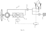
- Fig. 1a shows a schematic view of a wind energy installation 10 with a tower 11, a nacelle 12 and a rotor 14.
- the rotor carries a plurality of rotor blades 16 which take up power from the wind.
- Figure 1b shows an embodiment of a wind energy installation 10 with a double-fed asynchronous generator 18, which is connected on the rotor side via a converter 20 and on the stator side directly, that is, without the interposition of a converter, to an electrical transmission network 25.
- the wind energy installation can also be configured with a full converter.
- the feed into the electrical transmission network 25 takes place, for example, via a transformer 24.
- the wind energy installation 10 can be part of a wind park consisting of several wind energy installations 10, which for example, are connected to the electrical transmission network 25 via a parking network and a high-voltage transformer.
- the wind energy installation 10 has a control 26 which is connected to the converter 20 or its control for data communication.
- the control 26 is connected for data communication with a wind farm control 27, which is set up to control a plurality of wind energy installations 10.
- the method according to the invention can preferably be implemented in the control system 26.
- the invention can also be used at the wind farm level, in that setpoint values are specified by the wind farm controller 27 for each individual wind energy installation 10 and a frequency is measured in the feed point or in the farm network.
- Fig. 2 shows a schematic view of a controller 26 for operating the wind power installation.
- a PI controller 28 is used to determine a setpoint torque value N * for the converter from a control difference formed from a setpoint speed value n * and an actual value of the speed n meas .
- the nominal torque value N * is applied to a limiter 102.
- the limiter is a limiter with adjustable lower and upper limit (dynamic limiter).
- the lower limit N low and the upper limit N up are specified by a limiter control 200.
- the limiter control 200 can also have method sequences for braking the wind energy installation or, for other operating modes, have data records for specifying the lower and upper limits.
- the limiter 102 limits the applied torque setpoint value N * and provides a limited torque setpoint value N * '.
- the output value N * 'of the limiter 102 is used to control the generator torque of the wind energy installation.
- the generator torque is controlled depending on the generator used.
- the generator torque is set, for example, by controlling the converter.
- the generator torque is the electrically generated counter-torque to the mechanical torque of the rotor of the wind energy installation, which must be applied to the generator to generate electrical power.
- the setpoint value for the generator torque N * ' is applied to a controller of a converter 30.
- the virtual inertia mode uses a frequency f meas measured at the connection terminals of the wind energy installation .
- the measured frequency value f meas represents the actual value and allows a detection of a deviation from the nominal value of the network frequency.
- a park controller receives the measured frequency and forwards the measured frequency to all connected wind turbines without further processing or initiates a corresponding process sequence on the wind turbine.
- the frequency can also be measured locally for one or more systems, which avoids a transit time delay and communication overhead in the wind farm.
- the frequency measurement is evaluated in the control of the wind turbine in order to trigger the virtual inertia function. If the frequency falls below a trigger frequency f trigger as the first predetermined frequency value, then the virtual inertia function in the limiter control 200 is activated. If the virtual inertia function is activated, a corresponding boost signal is set and a series of operating states is run through: a boost mode and a recovery mode and possibly an intervening one Transitional operation. The triggering of the boost mode is described below using the Fig. 3 and the Fig. 4 described.
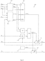
- Fig. 4 describes the generation of the boost signal flag boost and the setpoint value for the generator torque N * boost .
- the input variable for generating the boost signal flag boost is the actual value of the frequency f meas in the electrical supply network.
- the representation selected shows the boost signal represented as a flag bit, which could also be represented by a state machine or in some other way.
- the actual value of the frequency is compared with a first predetermined frequency value for the triggering frequency f trigger . If the actual value is smaller than the first predetermined frequency value, the output of the corresponding detection circuit 304 is set to 1.
- the output signal of the detection circuit 304 is present at the SET input of a flip-flop 306, so that when an underfrequency is detected at its Q output, the boost signal flag boost is output.
- the recognition circuit 310 If the actual value of the frequency in a comparison 308 is greater than a second predetermined frequency value for a reset frequency f reset , this is recognized in the recognition circuit 310 and a corresponding 1 value is applied to the input of the OR circuit 312 by the recognition circuit 310.
- the output of a comparator 316 is applied to the further input of the OR circuit 312, which outputs a 1 value when the boost signal flag boost is applied to the comparator for a boost duration T boost .
- the boost duration is recorded via a timer 314. Further conditions for the OR circuit 312 are described below.
- the output of the OR circuit 312 is applied to the RESET input of the flip-flop 306, which is used to set the Q output to zero, so that the boost signal flag boost is no longer output.
- the boost signal flag boost if generated by the flip-flop 306, is applied to an if-then branch 318. If the boost signal flag boost at the if-then branch 318 is present, this outputs a fixed electrical power P freeze at its output. The recorded power P freeze is fed back via a timing element 320. With the recorded power P freeze , the actual value of the electrical power before the boost signal occurs is recorded and used as the basis for the control during the boost operation. If the boost signal flag boost is not present or is no longer present at the if-then branch 318, the if-then branch 318 is set up to output an existing actual value of the electrical power P meas currently output by the wind energy installation as an else value.
- an additional power P inc to be provided is determined.
- different approaches can be selected, which can be selected with the selection elements 322 and 324.
- the nominal power P n is used.
- the recorded power P freeze can be used as the basis.
- Both variables are applied to selection element 322, which is set up, depending on which method is selected, to apply one of the variables to a multiplication element.
- the multiplication element is set up to scale the applied power value with a percentage value in order to determine the additional power P inc to be provided.
- the percentage value can be determined by a further switching element (not shown), for example as a function of the measured network frequency f meas .
- a frequency-dependent power value P boost (f) using a calculation element 326.
- a selection element 324 allows the selection of which of the determined power values is output from block 301 as P inc .
- Fixed power P freeze and additional power P inc added total to an aggregated nominal power value P by means of an addition element and divided by the current actual value of the speed n meas by means of a division element in order to determine the nominal value for the generator torque N * boost .
- a boost signal boost flag for a predetermined boost period T is generated boost.
- the boost mode can be exited prematurely when the mains frequency returns to its normal range. Further possible conditions for prematurely exiting the boost mode can be, for example, reaching a minimum generator speed below which the wind energy installation cannot be operated continuously.
- the boost signal flag boost when the minimum generator speed is reached, the wind energy installation can be avoided as a result of the boost operation.
- a minimum speed or a maximum speed reduction can be defined for the generator in order to avoid stalling and shutting down the wind energy installation.
- Corresponding input values can also be applied to the OR circuit 312 for this purpose, so that the boost mode is terminated prematurely when corresponding signals are present and the boost signal flag boost is reset.
- FIG. 4 illustrates the limiter control 200.
- FIG Fig. 3 To determine the upper and lower limits for the limiter 102, FIG Fig. 3 the actual value of the speed n meas , the actual value of the frequency f meas and the actual value of the electrical power P meas fed in at block 300.
- the block 300 has the relation to FIG Fig. 4 explained structure.
- Output variables from block 300 are the boost signal flag boost and the setpoint value for the torque N * boost in boost mode. Both signals are each applied to an if-then branch 201 or 202 and are checked by the branches against the if condition. In addition, as “otherwise” alternatives, the values provided for normal operation for the maximum torque N max and the minimum torque N min are available at branch 201 and 202, respectively. If the boost signal flag boost is set, then N * boost is output as the upper limit N * up 203 and as the lower limit N * low 204. If there is no boost signal flag boost , the value N max is set as the upper limit N * up and N min as the lower limit N * low for the limiter.
- the upper and lower limits determined by the if-then branches are applied to a uniform control block 400.
- the uniform control block 400 also has the boost signal and the actual value of the rotational speed n meas and the actual value of the electrical power P meas fed in as additional input signals. Added to this is the value of the power P aero currently available from the wind flowing onto the rotor of the wind energy installation .
- the upper and lower limits N low and N up for the limiter 102 are calculated from the applied setpoint values for the upper limit N * up and the lower N * low .
- the uniform control block 400 is set up to control the torque of the wind energy installation as a function of the input variables present in every operating state that can occur when a virtual inertia function is carried out.
- the functioning of the uniform control block 400 is based on Fig. 5 described in more detail.
- the conversion of the setpoint values N * low and N * up into control variables N low and N up takes place via ramp functions 401, 402.
- the ramp functions are switched to active via a ramp signal ramp active .
- Activating the The ramp function takes place when either the transition signal flag trans or the restoration signal flag rec is set by the switchover block 500.
- the setpoint N * obtained from the speed control for the generator torque at the comparator 418 must be smaller than the setpoint for the lower torque limit N * low .
- a second comparator is provided which additionally checks whether the setpoint value for the generator torque N * is possibly also greater than the setpoint value for the upper limit N * up .
- the necessary prerequisite for activating the ramp functions 401 and 402 is that the setpoint N * for the generator torque is outside of the setpoint values for the generator torque N * low and N * up .
- the ramp ramp low for the lower limit at the limiter is applied to the ramp function 401 and the ramp ramp up for the upper limit to the limiter is applied to the ramp function 402.
- the ramps are the maximum permissible changes over time for the generator torque.
- constant values for the ramp ramp up are specified in a memory block 420.
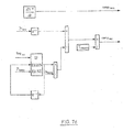
- Fig. 7 shows four exemplary embodiments for the calculations of the ramps in block 600.
- Figs. 7a and 7b relate to an operational management in which the wind energy installation changes directly to the recovery mode while Figs. 7c and 7d mark an intermediate transition area.
- the control signals ramp rec and ramp trans correspond to nominal values for the generator torque.
- Figure 7a shows the determination of a control signal ramp rec for the ramp function.
- the control signal ramp rec is obtained, for example, from a look-up table in which the change in the generator torque over time is plotted against the change in speed. The change in the speed is determined from the actual value of the speed n meas via a differentiating element 606.
- the look-up table 604 the relationship between the power P aero that can be taken from the wind and the electrical power P meas fed in is established.
- it must be taken into account that the rotational energy in the wind turbine increases due to an increasing speed, while the electrical power P el fed in also decreases as the generator torque N decreases.
- the maximum permissible change in the generator torque is limited via the ramp rec control signal.
- ramp rec can be applied both as ramp low to ramp function 401 and as ramp up to ramp function 402.
- Figure 7b shows an alternative embodiment in which a constant change term is added to the time derivative of the actual value of the speed dn ⁇ German / const is added.
- the change in rotational speed which is excessive in this way, is regulated by a controller 610.
- the controller 610 has a proportional element and can be designed as a P, PI or PID controller.
- the output variable of the controller 610 is the control signal ramp rec for controlling the ramp functions 401 and 402.
- Figure 7c shows an example for calculating the control signals ramp trans and ramp rec for the ramp functions, if a distinction is made between the transition mode and the recovery mode after the boost mode.
- a constant value becomes during the transient operation dN ⁇ German / const for the maximum permissible change in the generator torque and as a control signal ramp trans used. This specification is constant over time for the transition area. If a switch is made to restoration mode after the transition mode, a quotient variable is subtracted by a differential element based on the previously existing lower limit N low , which is set back by one time step by means of a timing element z -1 .
- the quotient variable is composed of the quotient which is formed from the difference between the power P aero available from the wind and a specified power difference ⁇ P.
- the denominator of the quotient is formed from the actual speed value.
- the power divided by the speed corresponds to a torque, whereby the quotient can be interpreted as a torque that is to be specified in order to set a constant power difference ⁇ P below the available power P aero .
- the generator torque present is reduced by this amount.
- the difference is divided by a predetermined period of time T sample by means of a division element in order to obtain a maximum permissible torque change as the control signal ramp rec for the ramp function.
- the central idea in recovery operation is that the power difference ⁇ P is no longer taken from the wind in order to increase the rotational energy of the wind turbine.
- control signal 602 for the ramp function is at a constant value during the transition mode dN ⁇ German / const set.
- the control signal ramp rec is generated with a similar approach as in FIG Figure 7c calculated.
- the torque to be subtracted applied to the differential element is not determined with the aid of a fixed, predetermined differential power, but on the basis of the actual power value P meas and the actual value for the speed.
- the recovery signal flag rec is applied to an if-then branch, the actual power value is kept constant via a time element z -1 , that is to say kept at the value before the system switched to recovery mode.
- the current actual value selected which is applied to a division link together with the power value.
- the core idea in this embodiment is that by retaining the power value, a correction of the generator torque is carried out in accordance with the actual value of the power when the recovery operation occurs.
- the switching from the boost signal (flag boost ) to the transition signal (flag trans ) or the recovery signal (flag rec ) is in the switching block 500 in FIG Fig. 5 shown. A possible more detailed structure for the switchover block 500 can be found in Fig. 6 .
- the boost signal flag boost is applied to the SET input of the flip-flop circuit 502, which is generated by a detection circuit 506 when the boost signal is reduced from the state on to the Status.
- Aus applies an input signal to the SET input of the flip-flop and thus generates a transition signal flag trans at the Q output of the flip-flop circuit 502.
- the end condition for the transition area is achieved by setting the RESET input of flip-flop 502. In order to terminate the transition range, it can either be assumed that the speed change is positive. This means that the speed increases again so that the transition signal flag trans can be reset.
- a signal can also be sent to the RESET input of the flip-flop circuit can be applied if the measured power P meas is less than the power P aero currently available from the wind.
- the transition area is ended and the transition signal flag trans is lowered.
- the detection unit 508 applies a signal to the SET input of the flip-flop circuit 504.
- the restoration signal flag rec is set accordingly at the Q output.
- the recovery operation then continues until the output signal of the comparator 510 is present at the RESET input of the flip-flop circuit 504, which signal indicates when the setpoint value for the generator torque N * is greater than the lower limit N low at the limiter.
- a further comparator (not shown) can be provided which compares whether the setpoint value N * is less than the upper limit value N up at the limiter.
- a signal for transition mode is set as soon as it is detected that boost mode has been deactivated and the signal for operation for virtual inertia is set.
- the transition mode can be deactivated if one of the two conditions is off Fig. 6 , which are present at the RESET input of the flip-flop circuit 502, is fulfilled.
- the second condition relates to the actual value of the electrical power fed in, for example in the form of the active power, compared to the estimated aerodynamic power P aero made available by the wind.
- a specifiable difference in the power is based on the losses between aerodynamic power and the power fed in and should be large enough to trigger Prevent oscillations in the estimated aerodynamic power or in the real power output.
- the recovery operation is initiated.
- the recovery mode is switched on as long as the torque setpoint for normal operation is limited by the lower limit of the limiter (see comparator 510). Deactivating the recovery mode indicates that the wind energy installation is returning to its normal operation.
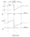
- Fig. 8 shows the qualitative progression of active power P, generator torque N, speed ⁇ and frequency f in the electrical supply network over time.
- the boost mode is triggered at time t 1 , at which the network frequency f falls below a value f trigger .
- Boost mode is triggered at time t 1 .
- the power fed in After a brief increase in the active power fed in and the generator torque N, the power fed in reaches a constant value which is P inc higher than the previously fed in power value P pre before the frequency drop occurred.
- the generator torque N increases and the speed ⁇ decreases.
- time t 2 is reached and the transition region takes place.
- the transition area is characterized in that the generator torque decreases with a constant gradient between the time period t 2 and t 3 . During this period of time, the speed stabilizes. The transition area is ended when a lower performance limit P dip is reached. In this way it is ensured that the power at the wind energy installation does not drop too much and the wind energy installation is shut down.
- the Recovery operation at time t 3 . In the recovery mode, both torque and speed increase until the recovery mode is completed.
- the electrical power fed in corresponds to the electrical power fed in before the frequency drop.
Landscapes
- Engineering & Computer Science (AREA)
- Power Engineering (AREA)
- Life Sciences & Earth Sciences (AREA)
- Sustainable Development (AREA)
- Sustainable Energy (AREA)
- Chemical & Material Sciences (AREA)
- Combustion & Propulsion (AREA)
- Mechanical Engineering (AREA)
- General Engineering & Computer Science (AREA)
- Control Of Eletrric Generators (AREA)
- Wind Motors (AREA)
Priority Applications (4)
| Application Number | Priority Date | Filing Date | Title |
|---|---|---|---|
| ES17186837T ES2861101T3 (es) | 2017-08-18 | 2017-08-18 | Procedimiento para el control de un aerogenerador |
| DK17186837.5T DK3444938T3 (da) | 2017-08-18 | 2017-08-18 | Fremgangsmåde til styring af en vindturbine |
| EP17186837.5A EP3444938B1 (de) | 2017-08-18 | 2017-08-18 | Verfahren zur steuerung einer windenergieanlage |
| US16/104,536 US10715066B2 (en) | 2017-08-18 | 2018-08-17 | Method for controlling a wind turbine |
Applications Claiming Priority (1)
| Application Number | Priority Date | Filing Date | Title |
|---|---|---|---|
| EP17186837.5A EP3444938B1 (de) | 2017-08-18 | 2017-08-18 | Verfahren zur steuerung einer windenergieanlage |
Publications (2)
| Publication Number | Publication Date |
|---|---|
| EP3444938A1 EP3444938A1 (de) | 2019-02-20 |
| EP3444938B1 true EP3444938B1 (de) | 2020-11-18 |
Family
ID=59655959
Family Applications (1)
| Application Number | Title | Priority Date | Filing Date |
|---|---|---|---|
| EP17186837.5A Active EP3444938B1 (de) | 2017-08-18 | 2017-08-18 | Verfahren zur steuerung einer windenergieanlage |
Country Status (4)
| Country | Link |
|---|---|
| US (1) | US10715066B2 (da) |
| EP (1) | EP3444938B1 (da) |
| DK (1) | DK3444938T3 (da) |
| ES (1) | ES2861101T3 (da) |
Families Citing this family (6)
| Publication number | Priority date | Publication date | Assignee | Title |
|---|---|---|---|---|
| CN109931230B (zh) * | 2017-12-19 | 2020-02-28 | 北京金风科创风电设备有限公司 | 检测风力发电机组的有功功率的方法和设备 |
| US11293403B2 (en) * | 2019-04-09 | 2022-04-05 | General Electric Company | System and method for preventing catastrophic damage in drivetrain of a wind turbine |
| US10868482B1 (en) * | 2019-05-28 | 2020-12-15 | General Electric Company | Dual-frequency filter for distinguishing between different types of grid events |
| EP4457435A1 (en) | 2021-12-29 | 2024-11-06 | Vestas Wind Systems A/S | Torque limiter based on current torque value |
| CN116365581B (zh) * | 2023-01-16 | 2024-05-03 | 山东大学 | 双馈风电机组故障穿越下的轴系扭振抑制方法及系统 |
| CN116398377A (zh) * | 2023-04-18 | 2023-07-07 | 盐城工学院 | 一种提升风力机动态响应性能的改进最优转矩法 |
Family Cites Families (19)
| Publication number | Priority date | Publication date | Assignee | Title |
|---|---|---|---|---|
| US6600240B2 (en) * | 1997-08-08 | 2003-07-29 | General Electric Company | Variable speed wind turbine generator |
| DK1467463T3 (da) * | 2003-04-09 | 2017-03-27 | Gen Electric | Vindmøllepark og fremgangsmåde til drift deraf |
| DE102007019907B4 (de) * | 2007-04-27 | 2009-04-30 | Nordex Energy Gmbh | Vorrichtung zur aktiven Dämpfung eines Triebstrangs bei einer Windenergieanlage |
| US20090055030A1 (en) * | 2007-08-21 | 2009-02-26 | Ingeteam, S.A. | Control of active power reserve in a wind-farm |
| EP2328259B2 (en) * | 2008-08-12 | 2024-01-03 | Ingeteam Power Technology, S.A. | System and method for power management in a photovoltaic installation |
| DE102008057934C5 (de) * | 2008-11-19 | 2020-09-17 | Nordex Energy Gmbh | Windenergieanlage mit einer zentralen Steuerungseinrichtung und einer Steuerungseinheit im Rotor sowie Verfahren zum Betreiben einer derartigen Windenergieanlage |
| DE102009014012B4 (de) * | 2009-03-23 | 2014-02-13 | Wobben Properties Gmbh | Verfahren zum Betreiben einer Windenergieanlage |
| JP2012143079A (ja) * | 2010-12-28 | 2012-07-26 | Mitsubishi Heavy Ind Ltd | ケーブル支持具 |
| US9728969B2 (en) * | 2011-05-31 | 2017-08-08 | Vestas Wind Systems A/S | Systems and methods for generating an inertial response to a change in the voltage of an electricial grid |
| US10519931B2 (en) * | 2011-05-31 | 2019-12-31 | Vestas Wind Systems A/S | Systems and methods for generating an inertial response to a change in the voltage of an electrical grid |
| DE102011105854B4 (de) * | 2011-06-03 | 2013-04-11 | Nordex Energy Gmbh | Verfahren zum Betreiben einer Windenergieanlage bei Auftreten eines Netzfehlers sowie eine solche Windenergieanlage |
| EP2532888B2 (en) * | 2011-06-08 | 2021-06-09 | Siemens Gamesa Renewable Energy A/S | Arrangement for generating a control signal for controlling a power output of a power generation system |
| EP2847457B1 (en) * | 2012-05-11 | 2021-10-27 | Vestas Wind Systems A/S | A power system and method for operating a wind power system with a dispatching algorithm |
| DE102012224067A1 (de) | 2012-12-20 | 2014-06-26 | Senvion Se | Windenergieanlage und Verfahren zum Regeln des elektrischen Moments einer Windenergieanlage bei einem Netzfehler |
| EP2954605B1 (en) * | 2013-02-07 | 2021-01-13 | Vestas Wind Systems A/S | Power plant&energy storage system for provision of grid ancillary services |
| IN2013CH06082A (da) * | 2013-12-26 | 2015-07-03 | Gen Electric | |
| DE102014000784A1 (de) * | 2014-01-22 | 2015-07-23 | Senvion Se | Windpark mit Vorsteuerung im Leistungsregler |
| DE102015208554A1 (de) * | 2015-05-07 | 2016-11-10 | Wobben Properties Gmbh | Verfahren zum Betreiben einer Windenergieanlage |
| ES2913122T3 (es) * | 2017-03-13 | 2022-05-31 | Nordex Energy Se & Co Kg | Método de control del suministro de potencia activa de un parque eólico, y dicho parque eólico |
-
2017
- 2017-08-18 EP EP17186837.5A patent/EP3444938B1/de active Active
- 2017-08-18 DK DK17186837.5T patent/DK3444938T3/da active
- 2017-08-18 ES ES17186837T patent/ES2861101T3/es active Active
-
2018
- 2018-08-17 US US16/104,536 patent/US10715066B2/en active Active
Non-Patent Citations (1)
| Title |
|---|
| None * |
Also Published As
| Publication number | Publication date |
|---|---|
| EP3444938A1 (de) | 2019-02-20 |
| DK3444938T3 (da) | 2021-02-22 |
| US20190058425A1 (en) | 2019-02-21 |
| US10715066B2 (en) | 2020-07-14 |
| ES2861101T3 (es) | 2021-10-05 |
Similar Documents
| Publication | Publication Date | Title |
|---|---|---|
| EP2556247B1 (de) | Dynamische trägheitsregelung | |
| EP2093419B1 (de) | Verfahren zum Betreiben einer Windenergieanlage und Windenergieanlage | |
| EP2457320B1 (de) | Verfahren zum betreiben einer windturbine sowie dazu geeignete windturbine | |
| EP3444938A1 (de) | Verfahren zur steuerung einer windenergieanlage | |
| EP3156646B1 (de) | Windenergieanlage mit einem drehzahl- und einem generatorregler | |
| EP2764239B1 (de) | Verfahren zum betreiben einer windenergieanlage und entsprechende windenergieanlage | |
| EP1665494A1 (de) | Verfahren zum betrieb bzw. regelung einer windenergieanlage sowie verfahren zur bereitstellung von primärregelleistung mit windenergieanlagen | |
| EP2647840A1 (de) | Verfahren zum Betreiben einer Windenergieanlage | |
| EP3533125B1 (de) | Verfahren zum betreiben einer windenergieanlage | |
| DE102007060958A1 (de) | Steuereinrichtung für Windenergieanlagen mit Netzausfallerkennung | |
| EP2284974A1 (de) | Verfahren zum Betrieb bzw. Regelung einer Windenergieanlage sowie Verfahren zur Bereitstellung von Regelleistung mit Windenergieanlage | |
| EP3719301B1 (de) | Verfahren zum betrieb einer windenergieanlage mit mindestens einem in seinem blatteinstellwinkel verstellbaren rotorblatt | |
| EP3810924B1 (de) | Leistungsreduzierter betrieb einer windenergieanlage | |
| EP3444939B1 (de) | Verfahren zur steuerung einer windenergieanlage | |
| EP3292301B1 (de) | Verfahren zum betreiben einer windenergieanlage | |
| EP2562414B1 (de) | Verfahren zum Betreiben einer Windenergieanlage bei Auftreten eines Netzfehlers mit einem Spannungsrückgang sowie eine solche Windenergieanlage | |
| EP2948678B1 (de) | Verfahren zur azimutverstellung einer windenergieanlage, azimutverstellsystem und windenergieanlage | |
| EP3983670B1 (de) | Verfahren zum steuern einer windenergieanlage | |
| EP3958425B1 (de) | Umrichterbasierte erzeuger und verfahren zum einspeisen elektrischer leistung | |
| EP4092264A1 (de) | Verfahren zum steuern einer windenergieanlage, windenergieanlage und windpark | |
| EP3176430B1 (de) | Verfahren zum überwachen einer windenergieanlage | |
| EP3382196B1 (de) | Windenergieanlage mit kurzschlussstromverbessertem anlagentransformator | |
| EP4632218A1 (de) | Verfahren zum steuern einer windenergieanlage bei einem sicherheitsstopp | |
| EP3511564A1 (de) | Verfahren und system zum steuern einer windenergieanlage | |
| WO2020008033A1 (de) | Verfahren zum einspeisen elektrischer leistung in ein elektrisches versorgungsnetz |
Legal Events
| Date | Code | Title | Description |
|---|---|---|---|
| PUAI | Public reference made under article 153(3) epc to a published international application that has entered the european phase |
Free format text: ORIGINAL CODE: 0009012 |
|
| STAA | Information on the status of an ep patent application or granted ep patent |
Free format text: STATUS: THE APPLICATION HAS BEEN PUBLISHED |
|
| AK | Designated contracting states |
Kind code of ref document: A1 Designated state(s): AL AT BE BG CH CY CZ DE DK EE ES FI FR GB GR HR HU IE IS IT LI LT LU LV MC MK MT NL NO PL PT RO RS SE SI SK SM TR |
|
| AX | Request for extension of the european patent |
Extension state: BA ME |
|
| STAA | Information on the status of an ep patent application or granted ep patent |
Free format text: STATUS: REQUEST FOR EXAMINATION WAS MADE |
|
| 17P | Request for examination filed |
Effective date: 20190819 |
|
| RBV | Designated contracting states (corrected) |
Designated state(s): AL AT BE BG CH CY CZ DE DK EE ES FI FR GB GR HR HU IE IS IT LI LT LU LV MC MK MT NL NO PL PT RO RS SE SI SK SM TR |
|
| REG | Reference to a national code |
Ref country code: DE Ref legal event code: R079 Ref document number: 502017008234 Country of ref document: DE Free format text: PREVIOUS MAIN CLASS: H02P0009020000 Ipc: F03D0007020000 |
|
| RIC1 | Information provided on ipc code assigned before grant |
Ipc: H02P 9/02 20060101ALI20200508BHEP Ipc: F03D 7/02 20060101AFI20200508BHEP Ipc: H02J 3/38 20060101ALI20200508BHEP |
|
| GRAP | Despatch of communication of intention to grant a patent |
Free format text: ORIGINAL CODE: EPIDOSNIGR1 |
|
| STAA | Information on the status of an ep patent application or granted ep patent |
Free format text: STATUS: GRANT OF PATENT IS INTENDED |
|
| INTG | Intention to grant announced |
Effective date: 20200622 |
|
| GRAS | Grant fee paid |
Free format text: ORIGINAL CODE: EPIDOSNIGR3 |
|
| GRAA | (expected) grant |
Free format text: ORIGINAL CODE: 0009210 |
|
| STAA | Information on the status of an ep patent application or granted ep patent |
Free format text: STATUS: THE PATENT HAS BEEN GRANTED |
|
| AK | Designated contracting states |
Kind code of ref document: B1 Designated state(s): AL AT BE BG CH CY CZ DE DK EE ES FI FR GB GR HR HU IE IS IT LI LT LU LV MC MK MT NL NO PL PT RO RS SE SI SK SM TR |
|
| REG | Reference to a national code |
Ref country code: GB Ref legal event code: FG4D Free format text: NOT ENGLISH |
|
| REG | Reference to a national code |
Ref country code: CH Ref legal event code: EP |
|
| REG | Reference to a national code |
Ref country code: DE Ref legal event code: R096 Ref document number: 502017008234 Country of ref document: DE |
|
| REG | Reference to a national code |
Ref country code: IE Ref legal event code: FG4D Free format text: LANGUAGE OF EP DOCUMENT: GERMAN |
|
| REG | Reference to a national code |
Ref country code: AT Ref legal event code: REF Ref document number: 1336059 Country of ref document: AT Kind code of ref document: T Effective date: 20201215 |
|
| RAP2 | Party data changed (patent owner data changed or rights of a patent transferred) |
Owner name: NORDEX ENERGY SE & CO. KG |
|
| REG | Reference to a national code |
Ref country code: DK Ref legal event code: T3 Effective date: 20210215 |
|
| REG | Reference to a national code |
Ref country code: NL Ref legal event code: MP Effective date: 20201118 |
|
| PG25 | Lapsed in a contracting state [announced via postgrant information from national office to epo] |
Ref country code: NO Free format text: LAPSE BECAUSE OF FAILURE TO SUBMIT A TRANSLATION OF THE DESCRIPTION OR TO PAY THE FEE WITHIN THE PRESCRIBED TIME-LIMIT Effective date: 20210218 Ref country code: PT Free format text: LAPSE BECAUSE OF FAILURE TO SUBMIT A TRANSLATION OF THE DESCRIPTION OR TO PAY THE FEE WITHIN THE PRESCRIBED TIME-LIMIT Effective date: 20210318 Ref country code: RS Free format text: LAPSE BECAUSE OF FAILURE TO SUBMIT A TRANSLATION OF THE DESCRIPTION OR TO PAY THE FEE WITHIN THE PRESCRIBED TIME-LIMIT Effective date: 20201118 Ref country code: FI Free format text: LAPSE BECAUSE OF FAILURE TO SUBMIT A TRANSLATION OF THE DESCRIPTION OR TO PAY THE FEE WITHIN THE PRESCRIBED TIME-LIMIT Effective date: 20201118 Ref country code: GR Free format text: LAPSE BECAUSE OF FAILURE TO SUBMIT A TRANSLATION OF THE DESCRIPTION OR TO PAY THE FEE WITHIN THE PRESCRIBED TIME-LIMIT Effective date: 20210219 |
|
| PG25 | Lapsed in a contracting state [announced via postgrant information from national office to epo] |
Ref country code: SE Free format text: LAPSE BECAUSE OF FAILURE TO SUBMIT A TRANSLATION OF THE DESCRIPTION OR TO PAY THE FEE WITHIN THE PRESCRIBED TIME-LIMIT Effective date: 20201118 Ref country code: BG Free format text: LAPSE BECAUSE OF FAILURE TO SUBMIT A TRANSLATION OF THE DESCRIPTION OR TO PAY THE FEE WITHIN THE PRESCRIBED TIME-LIMIT Effective date: 20210218 Ref country code: LV Free format text: LAPSE BECAUSE OF FAILURE TO SUBMIT A TRANSLATION OF THE DESCRIPTION OR TO PAY THE FEE WITHIN THE PRESCRIBED TIME-LIMIT Effective date: 20201118 Ref country code: IS Free format text: LAPSE BECAUSE OF FAILURE TO SUBMIT A TRANSLATION OF THE DESCRIPTION OR TO PAY THE FEE WITHIN THE PRESCRIBED TIME-LIMIT Effective date: 20210318 Ref country code: PL Free format text: LAPSE BECAUSE OF FAILURE TO SUBMIT A TRANSLATION OF THE DESCRIPTION OR TO PAY THE FEE WITHIN THE PRESCRIBED TIME-LIMIT Effective date: 20201118 |
|
| REG | Reference to a national code |
Ref country code: LT Ref legal event code: MG9D |
|
| PG25 | Lapsed in a contracting state [announced via postgrant information from national office to epo] |
Ref country code: HR Free format text: LAPSE BECAUSE OF FAILURE TO SUBMIT A TRANSLATION OF THE DESCRIPTION OR TO PAY THE FEE WITHIN THE PRESCRIBED TIME-LIMIT Effective date: 20201118 |
|
| PG25 | Lapsed in a contracting state [announced via postgrant information from national office to epo] |
Ref country code: SM Free format text: LAPSE BECAUSE OF FAILURE TO SUBMIT A TRANSLATION OF THE DESCRIPTION OR TO PAY THE FEE WITHIN THE PRESCRIBED TIME-LIMIT Effective date: 20201118 Ref country code: LT Free format text: LAPSE BECAUSE OF FAILURE TO SUBMIT A TRANSLATION OF THE DESCRIPTION OR TO PAY THE FEE WITHIN THE PRESCRIBED TIME-LIMIT Effective date: 20201118 Ref country code: CZ Free format text: LAPSE BECAUSE OF FAILURE TO SUBMIT A TRANSLATION OF THE DESCRIPTION OR TO PAY THE FEE WITHIN THE PRESCRIBED TIME-LIMIT Effective date: 20201118 Ref country code: EE Free format text: LAPSE BECAUSE OF FAILURE TO SUBMIT A TRANSLATION OF THE DESCRIPTION OR TO PAY THE FEE WITHIN THE PRESCRIBED TIME-LIMIT Effective date: 20201118 Ref country code: RO Free format text: LAPSE BECAUSE OF FAILURE TO SUBMIT A TRANSLATION OF THE DESCRIPTION OR TO PAY THE FEE WITHIN THE PRESCRIBED TIME-LIMIT Effective date: 20201118 Ref country code: SK Free format text: LAPSE BECAUSE OF FAILURE TO SUBMIT A TRANSLATION OF THE DESCRIPTION OR TO PAY THE FEE WITHIN THE PRESCRIBED TIME-LIMIT Effective date: 20201118 |
|
| REG | Reference to a national code |
Ref country code: DE Ref legal event code: R097 Ref document number: 502017008234 Country of ref document: DE |
|
| PLBE | No opposition filed within time limit |
Free format text: ORIGINAL CODE: 0009261 |
|
| STAA | Information on the status of an ep patent application or granted ep patent |
Free format text: STATUS: NO OPPOSITION FILED WITHIN TIME LIMIT |
|
| 26N | No opposition filed |
Effective date: 20210819 |
|
| PG25 | Lapsed in a contracting state [announced via postgrant information from national office to epo] |
Ref country code: IT Free format text: LAPSE BECAUSE OF FAILURE TO SUBMIT A TRANSLATION OF THE DESCRIPTION OR TO PAY THE FEE WITHIN THE PRESCRIBED TIME-LIMIT Effective date: 20201118 Ref country code: AL Free format text: LAPSE BECAUSE OF FAILURE TO SUBMIT A TRANSLATION OF THE DESCRIPTION OR TO PAY THE FEE WITHIN THE PRESCRIBED TIME-LIMIT Effective date: 20201118 Ref country code: NL Free format text: LAPSE BECAUSE OF FAILURE TO SUBMIT A TRANSLATION OF THE DESCRIPTION OR TO PAY THE FEE WITHIN THE PRESCRIBED TIME-LIMIT Effective date: 20201118 |
|
| PG25 | Lapsed in a contracting state [announced via postgrant information from national office to epo] |
Ref country code: SI Free format text: LAPSE BECAUSE OF FAILURE TO SUBMIT A TRANSLATION OF THE DESCRIPTION OR TO PAY THE FEE WITHIN THE PRESCRIBED TIME-LIMIT Effective date: 20201118 |
|
| REG | Reference to a national code |
Ref country code: CH Ref legal event code: PL |
|
| PG25 | Lapsed in a contracting state [announced via postgrant information from national office to epo] |
Ref country code: MC Free format text: LAPSE BECAUSE OF FAILURE TO SUBMIT A TRANSLATION OF THE DESCRIPTION OR TO PAY THE FEE WITHIN THE PRESCRIBED TIME-LIMIT Effective date: 20201118 |
|
| REG | Reference to a national code |
Ref country code: BE Ref legal event code: MM Effective date: 20210831 |
|
| GBPC | Gb: european patent ceased through non-payment of renewal fee |
Effective date: 20210818 |
|
| PG25 | Lapsed in a contracting state [announced via postgrant information from national office to epo] |
Ref country code: LI Free format text: LAPSE BECAUSE OF NON-PAYMENT OF DUE FEES Effective date: 20210831 Ref country code: CH Free format text: LAPSE BECAUSE OF NON-PAYMENT OF DUE FEES Effective date: 20210831 |
|
| PG25 | Lapsed in a contracting state [announced via postgrant information from national office to epo] |
Ref country code: IS Free format text: LAPSE BECAUSE OF FAILURE TO SUBMIT A TRANSLATION OF THE DESCRIPTION OR TO PAY THE FEE WITHIN THE PRESCRIBED TIME-LIMIT Effective date: 20210318 Ref country code: LU Free format text: LAPSE BECAUSE OF NON-PAYMENT OF DUE FEES Effective date: 20210818 |
|
| PG25 | Lapsed in a contracting state [announced via postgrant information from national office to epo] |
Ref country code: IE Free format text: LAPSE BECAUSE OF NON-PAYMENT OF DUE FEES Effective date: 20210818 Ref country code: GB Free format text: LAPSE BECAUSE OF NON-PAYMENT OF DUE FEES Effective date: 20210818 Ref country code: FR Free format text: LAPSE BECAUSE OF NON-PAYMENT OF DUE FEES Effective date: 20210831 Ref country code: BE Free format text: LAPSE BECAUSE OF NON-PAYMENT OF DUE FEES Effective date: 20210831 |
|
| PG25 | Lapsed in a contracting state [announced via postgrant information from national office to epo] |
Ref country code: CY Free format text: LAPSE BECAUSE OF FAILURE TO SUBMIT A TRANSLATION OF THE DESCRIPTION OR TO PAY THE FEE WITHIN THE PRESCRIBED TIME-LIMIT Effective date: 20201118 |
|
| P01 | Opt-out of the competence of the unified patent court (upc) registered |
Effective date: 20230602 |
|
| PG25 | Lapsed in a contracting state [announced via postgrant information from national office to epo] |
Ref country code: HU Free format text: LAPSE BECAUSE OF FAILURE TO SUBMIT A TRANSLATION OF THE DESCRIPTION OR TO PAY THE FEE WITHIN THE PRESCRIBED TIME-LIMIT; INVALID AB INITIO Effective date: 20170818 |
|
| REG | Reference to a national code |
Ref country code: AT Ref legal event code: MM01 Ref document number: 1336059 Country of ref document: AT Kind code of ref document: T Effective date: 20220818 |
|
| PG25 | Lapsed in a contracting state [announced via postgrant information from national office to epo] |
Ref country code: AT Free format text: LAPSE BECAUSE OF NON-PAYMENT OF DUE FEES Effective date: 20220818 |
|
| PG25 | Lapsed in a contracting state [announced via postgrant information from national office to epo] |
Ref country code: MK Free format text: LAPSE BECAUSE OF FAILURE TO SUBMIT A TRANSLATION OF THE DESCRIPTION OR TO PAY THE FEE WITHIN THE PRESCRIBED TIME-LIMIT Effective date: 20201118 |
|
| PG25 | Lapsed in a contracting state [announced via postgrant information from national office to epo] |
Ref country code: MT Free format text: LAPSE BECAUSE OF FAILURE TO SUBMIT A TRANSLATION OF THE DESCRIPTION OR TO PAY THE FEE WITHIN THE PRESCRIBED TIME-LIMIT Effective date: 20201118 |
|
| PGFP | Annual fee paid to national office [announced via postgrant information from national office to epo] |
Ref country code: ES Payment date: 20250917 Year of fee payment: 9 |
|
| PGFP | Annual fee paid to national office [announced via postgrant information from national office to epo] |
Ref country code: DE Payment date: 20250819 Year of fee payment: 9 Ref country code: DK Payment date: 20250821 Year of fee payment: 9 |
|
| PG25 | Lapsed in a contracting state [announced via postgrant information from national office to epo] |
Ref country code: TR Free format text: LAPSE BECAUSE OF FAILURE TO SUBMIT A TRANSLATION OF THE DESCRIPTION OR TO PAY THE FEE WITHIN THE PRESCRIBED TIME-LIMIT Effective date: 20201118 |