EP3447904A1 - Commande de bobines de moteur linéaire à stator déployé d'un stator de moteur linéaire à stator déployé - Google Patents
Commande de bobines de moteur linéaire à stator déployé d'un stator de moteur linéaire à stator déployé Download PDFInfo
- Publication number
- EP3447904A1 EP3447904A1 EP17187110.6A EP17187110A EP3447904A1 EP 3447904 A1 EP3447904 A1 EP 3447904A1 EP 17187110 A EP17187110 A EP 17187110A EP 3447904 A1 EP3447904 A1 EP 3447904A1
- Authority
- EP
- European Patent Office
- Prior art keywords
- llm
- transport
- coil
- controlled variable
- coils
- Prior art date
- Legal status (The legal status is an assumption and is not a legal conclusion. Google has not performed a legal analysis and makes no representation as to the accuracy of the status listed.)
- Granted
Links
Images

Classifications
-
- H—ELECTRICITY
- H02—GENERATION; CONVERSION OR DISTRIBUTION OF ELECTRIC POWER
- H02K—DYNAMO-ELECTRIC MACHINES
- H02K41/00—Propulsion systems in which a rigid body is moved along a path due to dynamo-electric interaction between the body and a magnetic field travelling along the path
- H02K41/02—Linear motors; Sectional motors
-
- H—ELECTRICITY
- H02—GENERATION; CONVERSION OR DISTRIBUTION OF ELECTRIC POWER
- H02P—CONTROL OR REGULATION OF ELECTRIC MOTORS, ELECTRIC GENERATORS OR DYNAMO-ELECTRIC CONVERTERS; CONTROLLING TRANSFORMERS, REACTORS OR CHOKE COILS
- H02P25/00—Arrangements or methods for the control of AC motors characterised by the kind of AC motor or by structural details
- H02P25/02—Arrangements or methods for the control of AC motors characterised by the kind of AC motor or by structural details characterised by the kind of motor
- H02P25/06—Linear motors
- H02P25/064—Linear motors of the synchronous type
-
- B—PERFORMING OPERATIONS; TRANSPORTING
- B60—VEHICLES IN GENERAL
- B60L—PROPULSION OF ELECTRICALLY-PROPELLED VEHICLES; SUPPLYING ELECTRIC POWER FOR AUXILIARY EQUIPMENT OF ELECTRICALLY-PROPELLED VEHICLES; ELECTRODYNAMIC BRAKE SYSTEMS FOR VEHICLES IN GENERAL; MAGNETIC SUSPENSION OR LEVITATION FOR VEHICLES; MONITORING OPERATING VARIABLES OF ELECTRICALLY-PROPELLED VEHICLES; ELECTRIC SAFETY DEVICES FOR ELECTRICALLY-PROPELLED VEHICLES
- B60L13/00—Electric propulsion for monorail vehicles, suspension vehicles or rack railways; Magnetic suspension or levitation for vehicles
- B60L13/03—Electric propulsion by linear motors
-
- B—PERFORMING OPERATIONS; TRANSPORTING
- B65—CONVEYING; PACKING; STORING; HANDLING THIN OR FILAMENTARY MATERIAL
- B65G—TRANSPORT OR STORAGE DEVICES, e.g. CONVEYORS FOR LOADING OR TIPPING, SHOP CONVEYOR SYSTEMS OR PNEUMATIC TUBE CONVEYORS
- B65G54/00—Non-mechanical conveyors not otherwise provided for
- B65G54/02—Non-mechanical conveyors not otherwise provided for electrostatic, electric, or magnetic
-
- H—ELECTRICITY
- H02—GENERATION; CONVERSION OR DISTRIBUTION OF ELECTRIC POWER
- H02K—DYNAMO-ELECTRIC MACHINES
- H02K41/00—Propulsion systems in which a rigid body is moved along a path due to dynamo-electric interaction between the body and a magnetic field travelling along the path
- H02K41/02—Linear motors; Sectional motors
- H02K41/03—Synchronous motors; Motors moving step by step; Reluctance motors
-
- H—ELECTRICITY
- H02—GENERATION; CONVERSION OR DISTRIBUTION OF ELECTRIC POWER
- H02P—CONTROL OR REGULATION OF ELECTRIC MOTORS, ELECTRIC GENERATORS OR DYNAMO-ELECTRIC CONVERTERS; CONTROLLING TRANSFORMERS, REACTORS OR CHOKE COILS
- H02P25/00—Arrangements or methods for the control of AC motors characterised by the kind of AC motor or by structural details
- H02P25/02—Arrangements or methods for the control of AC motors characterised by the kind of AC motor or by structural details characterised by the kind of motor
- H02P25/06—Linear motors
-
- H—ELECTRICITY
- H02—GENERATION; CONVERSION OR DISTRIBUTION OF ELECTRIC POWER
- H02P—CONTROL OR REGULATION OF ELECTRIC MOTORS, ELECTRIC GENERATORS OR DYNAMO-ELECTRIC CONVERTERS; CONTROLLING TRANSFORMERS, REACTORS OR CHOKE COILS
- H02P25/00—Arrangements or methods for the control of AC motors characterised by the kind of AC motor or by structural details
- H02P25/02—Arrangements or methods for the control of AC motors characterised by the kind of AC motor or by structural details characterised by the kind of motor
- H02P25/06—Linear motors
- H02P25/062—Linear motors of the induction type
-
- H—ELECTRICITY
- H02—GENERATION; CONVERSION OR DISTRIBUTION OF ELECTRIC POWER
- H02P—CONTROL OR REGULATION OF ELECTRIC MOTORS, ELECTRIC GENERATORS OR DYNAMO-ELECTRIC CONVERTERS; CONTROLLING TRANSFORMERS, REACTORS OR CHOKE COILS
- H02P6/00—Arrangements for controlling synchronous motors or other dynamo-electric motors using electronic commutation dependent on the rotor position; Electronic commutators therefor
- H02P6/006—Controlling linear motors
-
- H—ELECTRICITY
- H02—GENERATION; CONVERSION OR DISTRIBUTION OF ELECTRIC POWER
- H02K—DYNAMO-ELECTRIC MACHINES
- H02K41/00—Propulsion systems in which a rigid body is moved along a path due to dynamo-electric interaction between the body and a magnetic field travelling along the path
- H02K41/02—Linear motors; Sectional motors
- H02K41/03—Synchronous motors; Motors moving step by step; Reluctance motors
- H02K41/031—Synchronous motors; Motors moving step by step; Reluctance motors of the permanent magnet type
Definitions
- the present invention relates to a method and a device for controlling the movement of two transport units of a long stator linear motor with a plurality n of LLM coils arranged side by side in the direction of movement, wherein the first transport unit has a first number of first drive magnets arranged side by side in the movement direction, and the second Transport unit has a second number of juxtaposed in the direction of movement second drive magnet, the movement of the first transport unit is controlled by an associated first transport controller by the first transport controller of a first subset of the plurality n LLM coils each vorfoundde electrical quantities calculated, the movement of the second transport unit is controlled by an associated second transport controller by the second transport controller of a second subset of the plurality n LLM coils each calculated and prespecified electrical quantities coagul whether an LLM coil is specified as an electrical variable, a first controlled variable from the first transport controller and the same LLM coil as electrical size simultaneously a second controlled variable from the second transport controller is specified and a long stator linear motor with such a device.
- a long-stator linear motor In a long-stator linear motor (LLM), a plurality of juxtaposed LLM electrical coils forming the stator are stationarily arranged side by side along a transport path. On a transport unit, a number of drive magnets, either as permanent magnets or as an electrical coil or short-circuit winding, arranged, which cooperate with the LLM coils.
- the long stator linear motor can be designed as a synchronous machine, either self-excited or externally excited, or as an asynchronous machine. Due to the interaction of the (electro) magnetic fields of the drive magnets and the LLM coils, a driving force acts on the transport unit, which moves the transport unit forward in the direction of movement. This is done by driving the individual LLM coils for controlling the magnetic flux.
- the size of the driving force is influenced and the transport unit can be moved in the desired manner along the transport path. It is also possible to arrange along the transport path a plurality of transport units whose movements can be controlled individually and independently by the respective cooperating with a transport unit drive coils are energized.
- an electrical variable is specified by a transport controller, which applies a terminal voltage to the coil terminals either directly or via a downstream coil regulator or impresses a coil current in the LLM coil.
- Long stator linear motors are characterized in particular by a better and more flexible utilization over the entire working range (speed, position, speed, acceleration), an individual regulation / control of the movable transport units (shuttles), an improved energy utilization, a reduction in maintenance costs due to the reduced number of wear parts, a simple replacement of the transport facilities, efficient monitoring and fault detection and an optimization of the product flow.
- Increasingly long-stator linear motors are used as a replacement for conventional continuous conveyors or rotational-to-linear translation units (eg rotary motor on conveyor belt, belts, chains, etc.) to meet the requirements of modern, flexible logistics units. Examples of such long stator linear motors may be the WO 2013/143783 A1 , the US 6,876,107 B2 , the US 2013/0074724 A1 or the WO 2004/103792 A1 be removed.
- a moving magnetic field is generated, which cooperates with the drive magnets of the transport units.
- terminal voltages or coil currents of the LLM coils are regulated via a transport regulator or via a downstream coil regulator.
- a transport controller is used per transport unit, which controls, analogous to the rotary case, starting from a d / q coordinate system to be applied to the individual LLM coils currents and voltages ,
- a transport unit thus moves along the LLM coils of the stator, wherein a transport controller actuates the adjacent LLM coils of the stator, so to speak, by an electromagnetic field.
- first transport unit can stand still and another transport unit can move toward the first transport unit, or two transport units can have opposite directions.
- security measure to prevent it.
- the US 2017/0117829 A1 handles a drive of the coil currents of LLM coils, minimizing copper losses.
- the LLM coils of a long stator linear motor are also influenced by the drive magnets of the transport units.
- Coil units consist of a composite of coils. As is known, the sum of the drive magnets of a transport unit must be greater than the individually controllable LLM coils of the stator, since otherwise the transport unit could not be moved.
- the coil current of the mean LLM coil of this coil unit is set to zero. However, this "missing" current is compensated by the other LLM coils of the coil unit.
- a coil current to be applied to the coil unit is calculated when a transport unit is only is controlled by a coil unit, that overlaps with the coils of the respective coil unit.
- This object is achieved by a method in which the LLM coil either a further controlled variable, which results from a predetermined function f from the first control variable and / or the second controlled variable, the LLM coil are specified or the coil terminals of the LLM Coil are short-circuited.
- a control unit which is connected to the first and second transport controller and an LLM coil and is designed to check whether the LLM coil is given a first controlled variable by the first transport controller as electrical variable and the same LLM coil.
- Coil is specified as an electrical variable at the same time a second controlled variable from the second transport controller and in this case the LLM coil as an electrical variable either a further controlled variable, which results from a predetermined function f from the first controlled variable and / or the second controlled variable, or short-circuit the coil terminals of the LLM coil.
- the electrical variable, or the controlled variable can directly represent a terminal voltage or a coil current of the LLM coils and are fed directly to the LLM coils or also fed to an amplifier circuit.
- the amplifier circuit can include a coil regulator, ie a voltage regulator or current regulator, and further, for example, a terminal voltage (eg a PWM signal) to the coil terminals of the LLM coil invest.
- the amplifier circuit for providing the necessary power can thus be provided directly on the transport controller, on a coil controller or on the coil.
- the controlled variable represents a terminal voltage
- the controlled variable can also be realized as a pure control variable, which is only amplified.
- transport units In the case of transport units according to the prior art, it may occur that two transport units approach one another except for physical contact, with which an LLM spool would be overlapped by both transport units.
- the transport units have so far been designed such that the drive magnets are placed in the middle and do not extend to the edge of the transport unit.
- the LLM coil despite overlapping with the transport units, not be overlapped by drive magnets of both transport units simultaneously.
- the transport units can now be made more compact, or else the drive magnets cover a larger area of the transport units because a potential conflict in the control of an LLM coil is detected and resolved.
- the LLM coil in question would receive from the first transport controller a first controlled variable as desired value for the electrical variable, and from the second transport controller a second controlled variable as (other) desired value. According to the invention, however, an unambiguous specification exists for the regulation of the electrical size of each LLM coil and there is no conflict between the first transport controller and the second transport controller, which originally wanted to specify a first or second controlled variable to the same LLM coil.
- the two transport units are e.g. so close to each other that the drive magnets of both transport units overlap at least partially with the same LLM coil, so this would mean that the electrical size of this LLM coil should be controlled by two transport controllers simultaneously. It should thus be given a first and a second controlled variable as electrical variable, which would lead to a conflict.
- the further controlled variable results from a predetermined function f from the first controlled variable and / or the second controlled variable.
- the coil terminals of the LLM coil can also be short-circuited.
- “Overlapping" the drive magnets with the LLM coils not only means that the position of the LLM coils and the drive magnets overlap, but also that sufficient magnetic coupling between the LLM coil and the drive magnet of the respective transport unit, which may also be the case on a drive magnet, for example due to stray fields at a small distance (corresponding to a fraction of the longitudinal extent of the LLM coil) in addition to the LLM coil ,
- a transport controller regulates the electrical size of an LLM coil that does not overlap with the transport controller or the corresponding transport unit associated drive magnet.
- This LLM coil the electrical size is controlled, can be seen in the direction of movement directly in front of and behind the transport unit.
- Such regulation of electrical quantities of LLM coils, which are located next to the LLM coil overlapping with the drive magnets, is also called “soft-mapping”.
- the regulation of the electrical size of an LLM coil which completely overlaps with the drive magnets of a transport unit is referred to as "hard-mapping", with a partial overlap as “medium-mapping".
- the control of two LLM coils per transport unit is sufficient, especially when the drive magnets of a transport unit extend over the length of three LLM coils. At least as many LLM coils should be controlled as are at least partially overlapped by the drive magnets of the respective transport unit. Investigations of the attraction force of the transport unit on the stator and the acting driving force have shown that current ripple can be reduced by using further LLM coils. Also, other properties of the system, such as a smoother propulsion or better efficiency can be achieved by controlling additional coils. However, this requires a "soft-mapping" of these other LLM coils.
- a regulation of six LLM coils for controlling a transport unit in the form of a soft mapping may be advantageous in order to produce a symmetrical three-phase system.
- six LLM coils are controlled, i. that so many LLM coils before or after the LLM coils which overlap in the direction of movement with the drive magnets of this transport unit, are controlled in the form of a soft mapping that per transport unit in total the electrical variables of six LLM coils are controlled ,
- the LLM coil with the first drive magnet of the first transport unit overlaps partially or completely and does not overlap with the second drive magnet of the second transport units.
- the first transport controller would want to control the electrical variable after a hard mapping (full overlap) or a medium mapping (partial overlap) to the first controlled variable and the second transport controller, the electrical variable after a soft-mapping to the would like to regulate the second controlled variable, what without the inventive solution too would lead to a conflict.
- the control unit takes over the first controlled variable from the first transport controller and predefines the LLM coil as the electrical variable.
- the second controlled variable of the second transport controller has no effect on the electrical size. This means that in this case the hard / medium mapping dominates over the soft mapping.
- the further controlled variable may correspond to the second controlled variable, which is particularly advantageous when the LLM coil partially or completely overlaps with the second drive magnet of the second transport unit and does not overlap with the drive magnets of the first transport units.
- the second transport controller would like to control the electrical size of the LLM coil after a hard mapping or a medium mapping to the first controlled variable and the first transport controller, the electric size of the same LLM coil after a soft-mapping to the second controlled variable.
- the control unit takes over the second controlled variable from the second transport controller and the LLM coil specifies as an electrical variable.
- the first controlled variable of the first transport regulator has no effect on the electrical quantity, i. that in this case too, hard / medium mapping dominates via soft-mapping.
- the further controlled variable may also be smaller in magnitude than the first controlled variable and smaller than or equal to the second controlled variable.
- the further controlled variable has a value between the first controlled variable and the second controlled variable, wherein it is particularly advantageous if the further controlled variable corresponds to an average value of the first controlled variable and the second controlled variable, wherein the mean value also, e.g. depending on the respective position of the transport unit, can be weighted.
- the further controlled variable may also correspond to the first or the second controlled variable, for example, depending on whether the first or second controlled variable is smaller or larger, or also assume a specific or calculated value below or above the first / second controlled variable, which also depends, for example can be whether the first or second controlled variable is smaller / larger.
- the conflict of a first control variable to be given by a first transport controller and a second controlled variable to be given by a second transport controller to the same LLM coil in the event that the first and the second drive magnets partially overlap the LLM coil - ie from the first and the second transport controller is provided a medium mapping - regulated by the control unit of the LLM coil another control variable is specified as an electrical variable to the LLM coil or the coil terminals of the LLM coil are short-circuited.
- first and second controlled variable is to be specified as the electrical variable of the same LLM coil on the basis of an intended soft mapping, or if the first (or second) controlled variable to be preset is on a medium / hard mapping and the second (or first) To be given control variable based on a soft-mapping, another control variable can be specified as electrical size - or the coil terminals of the LLM coil are short-circuited - to solve the conflict.
- the further controlled variable may in turn result from a predetermined function f from the first controlled variable and / or the second controlled variable and thus, for example, equal to the first controlled variable or the second controlled variable, be smaller than or equal to the first controlled variable and the second controlled variable, or from one Mean value of the first and the second controlled variable result.
- the control unit that causes the specification of the further controlled variable or the short-circuiting of the coil clamps of the LLM coil can be an integral part of the first and / or second transport controller or be connected between the first and second transport controller and the LLM coil.
- one control unit per LLM coil is ever present.
- a long-stator linear motor with a large number of LLM coils arranged side by side in the direction of movement can thus be provided with a device according to the invention for regulating the movement of two transport units.
- the position of the driving magnets, and thus also of the transport units, can e.g. be determined by means of position sensors, which are usually already integrated in the long stator linear motor. If drive magnets of a transport unit overlap an LLM coil, then it can be assumed that the drive magnets and LLM coil are in magnetic interaction and the electrical quantity is specified by the transport controller associated with the transport unit in question. If an LLM coil is given an electrical variable only by a transport controller, then this electrical quantity can be regulated by the transport controller in a known manner.
- the transport controllers could also regulate the electrical variables by means of a coil control unit assigned to the respective LLM coil.
- the coil control units would thus be subordinate to the transport controllers.
- several coil control units could be integrated in a common unit.
- a transport device in the form of a long stator linear motor is exemplified.
- a transport section 1 generally forms part of a long stator of an LLM and can also be subdivided further in a known manner, for example into a number of individual transport segments, which can also form a non-self-contained webs.
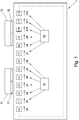
- the transport device consists in Fig. 1 By way of example only from a transport section 1.
- a plurality n of LLM electrical coils L1, ..., Ln arranged with a number of drive magnets Y1, Y2 on a number of transport units T1, T2 interact.
- the individual LLM coils L1, ..., Ln for each of the transport units T1, T2 generates a driving force, the transport units T1 , T2 in the longitudinal direction along the transport path, or the transport section 1 individually (speed, acceleration, orbit, direction) and independently (except for the avoidance of possible collisions) of the other transport units T1, T2 moves.
- the transport controllers R1, R2 independently by controlling the electrical variables U1, ..., Un, the individual LLM coils L1, ..., Ln for each of the transport units T1, T2 generates a driving force, the transport units T1 , T2 in the longitudinal direction along the transport path, or the transport section 1 individually (speed, acceleration, orbit, direction) and independently (except for the avoidance of possible collisions) of the other transport units T1, T2 moves.
- preferably only those LLM coils L1, ..., Ln are supplied by predetermining an electrical variable directly or via a further coil regulator, which interact with the drive magnets Y1, Y2 of the transport units T1, T2, or with
- LLM coils L1, ..., Ln should be electrically supplied which are overlapped by driving magnets Y1, Y2 (in FIG Fig.1 for example, the LLM coils L2, L3, L4, L5 for the transport unit T1).
- a number of LLM coils L1,..., Ln can also be electrically supplied in the direction of movement in front of and behind the drive magnets Y1, Y2 (in FIG Fig.1
- the LLM coils L1, L6 for the transport unit T1 which leads to a more uniform movement of the transport units T1, T2.
- the transport controllers R1, R2 it is only necessary for the transport controllers R1, R2 to supply the LLM coils L1,..., Ln electrically, which overlap, ie cooperate, with a transport unit T1, T2, or their drive magnets Y1, Y2.
- the propulsive forces generated need not be the same for the individual transport units T1, T2.
- the coil currents impressed into the respective LLM coils L1,..., Ln do not necessarily have to be the same size.
- the transport controllers R1, R2 can also regulate the electrical variables U1,..., U2 of LLM coils L1,..., Ln, which do not interact with the drive magnets Y1, Y2 of the respective transport units Y1, Y2, which is referred to here Soft mapping is called.
- transport controller R1, R2 often for each to be moved transport unit T1, T2 continuously set a position (equivalent speed specification) (for example, from a higher system control or externally), in a conventional manner, in each time step of the scheme in for the movement required electrical variables U1, ..., Un are implemented.
- a transport controller R1, R2 could of course also be constructed in a hierarchical manner in a known manner, for example with a position controller, speed controller and / or force controller for each transport unit T1, T2 and a coil controller, i. Current regulator and / or voltage regulator, for each LLM coil L1, ..., Ln, etc.
- the electrical quantities U1,..., Un can directly represent a terminal voltage or a coil current of the LLM coils L1,..., Ln, but can also be supplied to an amplifier circuit, which in turn supplies a terminal voltage to the coil terminals of the LLM coils L1, ..., Ln applies.
- An amplifier circuit can be provided directly at the transport regulators R1, R2, at additional coil regulators or also at the LLM coil L1,..., Ln. For the sake of clarity were in the Figures 1-3 No amplifier circuits or additional coil controllers drawn.
- the drive magnets Y1, Y2 can be designed as electromagnets (excitation coils) and / or as permanent magnets. Usually are per transport unit T1, T2, a number of juxtaposed in the direction of movement drive magnets Y1, Y2, wherein in the Figures 1-3 for ease of illustration only one drive magnet Y1, Y2 per transport unit T1, T2 is shown.
- the LLM coils L1,..., Ln can be arranged on a ferromagnetic core (for example, an iron laminated core), or, of course, can also be made coreless.
- the first transport controller R1 and the second transport controller R2 regulate in Fig. 1-3 the electrical variables U1,..., Un of the respective LLM coils L1,..., Ln are such that the first transport unit T1 associated with the first transport controller R1 or second transport controller R2 or second transport unit T2 is moved along the stator.
- the transport controllers R1, R2 can thus control all electrical variables U1,... Un of all LLM coils L1,..., Ln cooperating with a transport unit T1, T2, the electrical variables U1, the position of the respective transport unit T1, T2 in the direction of movement along the stator depends.
- the first transport controller R1 would control the second electrical quantity U2, the third electrical quantity U3, the fourth electrical quantity U4 and the fifth electrical quantity U5 (indicated by solid arrows), since the second LLM coil L2, the third LLM coil L3, the fourth LLM coil L4 and the fifth LLM coil L5 with the first drive magnet Y1 of the first transport unit T1 overlap.
- the first transport controller R1 thus calculates the predetermined electrical quantities U2, U3, U4, U5 to the respective LLM coils L2, L3, L4, L5, which corresponds to a first subset of the plurality n of coils L1, ..., Ln.
- the second transport controller R2 would equally regulate the eighth electrical quantity U8, the ninth electrical quantity U9, the tenth electrical quantity U10 and the eleventh electrical quantity U11 (also indicated by solid arrows), since the eighth LLM coil L8 is the ninth LLM coil L9, the tenth LLM coil L10 and the eleventh LLM coil L11 overlap with the second drive magnet Y2 of the second transport unit Z2.
- the second transport controller R2 thus calculates the predetermined electrical variables U8, U9, U10, U11 to the respective LLM coils L8, L9, L10, L11, which corresponds to a second subset of the plurality n coils L1, ..., Ln.
- a transport controller R1, R2 takes over the control of LLM coils within the scope of a soft mapping, which are located in front of and behind the respective transport unit T1, T2 in the direction of movement, ie in front of and behind the LLM coils which completely or partially overlap with the drive magnets Y1, Y2 of the respective transport unit T1, T2, for example, the LLM coils L1, L6, L7, L12 in Fig.1 ,
- the first subset is thus extended by the LLM coils L1 and L6, the second subset is extended by the LLM coils L7 and L12. Also in this case is at the position of the transport units T1, T2 after Fig. 1 a clear regulation of the individual electrical variables U1, U6, U7, U12 of the LLM coils L1, L6, L7, L12 guaranteed because none of the transport controller R1, R2 tries to control the same electrical variables U1, U6, U7, U12.
- the first and second subset do not overlap again.
- Soft-mapping rules are used in the Figures 1-3 indicated by dotted arrows.
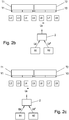
- Fig. 2a is a section of the transport from Fig. 1 shown, with two transport units T1, T2 are positioned side by side.
- a control unit 2 is connected between the two transport controllers R1, R2 and the LLM coils L1, ..., Ln.
- a control unit 2 it would also be possible for a control unit 2 to be present for several or each LLM coil L1,..., Ln or for the control unit (s) 2 to be / are an integral part of the transport controllers R1, R2.
- the first transport unit T1 is located as in Fig. 1 in a position where the second LLM coil L2, the third LLM coil L3, the fourth LLM coil L4 and the fifth LLM coil L5 overlap with the first drive magnet Y1 of the first transport unit Z1.
- the second transport unit T2 is located next to the first transport unit T1, whereby the second drive magnet Y2 overlaps the fifth LLM coil L5, the sixth LLM coil L6, the seventh LLM coil L7, and the eighth LLM coil L8.
- the electrical quantities U2, U3, U4, U6, U7, U8, since no conflict between the transport controllers R1, R2 occurs here, are not influenced by the control unit 2 and the LLM coils L2, L3, L4, L6, L7, L8 specified.
- the further electrical variables U1, U9, U10, U11, U12,..., Un are in Fig. 2a not actively controlled by the transport controllers R1, R2 and thus not by the control unit 2. These non-actively controlled electrical variables U1, U9, U10, U11, U12, ..., Un could of course be controlled by the control unit 2 to zero.
- the fifth LLM coil L5 is partially overlapped with both the first drive magnet Y1 and the second drive magnet Y2, whereby the fifth LLM coil L5 is part of the first subset and the second subset.
- the method according to the invention is thus intended to be described in US Pat Fig. 2a
- the first transport controller R1 wants to specify a first controlled variable Ux 'and the second transport controller R2 a second controlled variable Ux "to the relevant LLM coil Lx (here L5), ie that the first transport controller R1 and the second transport controller form a medium mapping
- control unit 2 recognizes this coil conflict and gives the relevant LLM coil Lx (here L5) a further controlled variable Ux before.
- the respective actual position of the transport unit T1, T2 is always known, for example, the respective actual positions can be detected with suitable and known position sensors. After the construction and the geometry of the transport units T1, T2 and also the arrangement of the drive magnets Y1, Y2 are known, it can always be recognized with the known positions when such a coil conflict occurs.
- the coil terminals of the relevant (here the fifth) LLM coil could be short-circuited, which means that neither of the two transport controller active a control variable Ux ', Ux "is given to the relevant (here fifth) LLM coil L5, which is the conflict is eliminated as well.
- Fig. 2b shows the constellation Fig. 2a with focus on the sixth LLM coil L6, wherein the electrical variables of the other LLM coils L1, ..., L5, L7, ..., Ln are not considered here.
- a soft mapping is provided, whereby the first transport controller R1 intends to specify a first controlled variable Ux 'to the sixth LLM coil L6, which is indicated by the arrow from the first transport controller R1 to the control unit 2.
- the sixth LLM coil L6 would, however, also be controlled by the second transport controller R2 as part of a hard mapping which specifies the second controlled variable Ux ", which is indicated by the arrow from the second transport controller R1 to the control unit.
- a further controlled variable Ux is given to the sixth LLM coil L6 as a solution to this conflict by the control unit 2.
- the second controlled variable Ux "or the first controlled variable Ux ' can be used particularly advantageously as a further control variable Ux the second controlled variable Ux "or the first controlled variable Ux ', wherein at the same time intentional medium / hard and soft-mapping control of the same LLM coil Lx (here medium mapping of LLM coil L6) medium / hard-mapping is preferred over the soft-mapping, ie, that the second controlled variable Ux "which is advantageously provided directly by the second transport controller R2 from the control unit 2 as a further controlled variable Ux of the sixth LLM Coil L6 is specified.
- the first Transport controller R1 provided first controlled variable Ux ' would thus have no effect on the specified to the sixth LLM coil L6 further control variable Ux.
- Fig. 2c shows the constellation Fig. 2a in a similar way as in Fig. 2b , but with focus on the fourth LLM coil L4, which is part of the first subset and the second subset here.
- the first transport controller R1 intends to specify a first controlled variable Ux 'in the context of a soft mapping to the fourth LLM coil L4 (arrow from the first transport controller R1 to the control unit 2).
- the second transport controller R2 also intends to predefine a second controlled variable Ux "of the fourth LLM coil L4 (arrow from the second transport controller R1 to the control unit 2) in a hard mapping.
- control unit 2 also gives the fourth LLM coil L4 a
- Medium / hard and soft-mapping control of an LLM coil Lx (here L4) the medium / hard-mapping is preferred - so here the medium mapping by the first controlled variable Ux 'which advantageously provided directly from the first transport controller R1 and the control unit 2 is forwarded to the fourth LLM coil.
- the second transport controller in this case would have no influence on the fourth electrical quantity Ux of the fourth LLM coil L4.
- the electrical quantity U1 of the first LLM coil L1 would also be regulated by the first transport controller R1, or the electrical quantity U9 of the ninth LLM coil L9 by the second transport controller R2.
- the respective other transport controller R1, R2 does not want to control the electrical variable U1, U9 of the respective LLM coil L1, L9 and there is no conflict that would have to be resolved by a control unit 2.
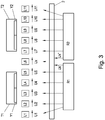
- a constellation is shown in which two transport units T1, T2 approach, or are already approximated, that none of the LLM coils L1, ..., Ln is overlapped by the drive magnets Y1, Y2 of both transport units T1, T2.
- the first transport unit T1 is again in a position in which the second LLM coil L2, the third LLM coil L3, the fourth LLM coil L3 and the fifth LLM coil L5 overlap with the first drive magnet Y1 of the first transport unit T1 ,
- the first transport controller R1 controls the second electrical quantity U2, the third electrical quantity U3, the fourth electrical quantity U4 and the fifth electrical quantity U5.
- the second transport unit T2 is closer than in Fig.
- the sixth LLM coil L6 overlaps neither with the first drive magnet Y1, nor with the second drive magnet Y2.
- the first transport controller R1 of the sixth LLM coil L6 wants to specify a first controlled variable Ux 'and the second transport controller R2 to the sixth LLM coil L6 specify a second controlled variable Ux ", with which the sixth LLM coil L6 is part of the first subset and the second subset, as is the case here by way of example, since the sixth LLM coil L6 adjoins the one with According to the invention, a further controlled variable Ux is supplied to the sixth LLM coil L6 by the control unit 2.
- the further predetermined controlled variable Ux corresponds to the mean value of first controlled variable Ux 'and the second controlled variable Ux ", but can also be one of the two controlled variables Ux', Ux" correspond, or it can be the coil terminals of the respective LLM coil L6 short-circuited, so no electrical variable active to the respective LLM coil (here L6) are given.
- a further controlled variable Ux can be preset by the control unit.
- the further controlled variable corresponds to an average of the first controlled variable Ux 'and the second controlled variable Ux ".
- it can also be, for example, equal to the first controlled variable Ux 'or equal to the second controlled variable Ux ".
- the first transport controller R1 would also control the controlled variable U1 of the first LLM coil L1, and the controlled variable U11 of the eleventh LLM coil L11 would be controlled by the second transport controller R2.
- the respective other transport controller R1, R2 does not want to regulate the electrical variable U1, U11 of the respective LLM coil L1, L11, whereby here too the respective electrical variables U1, U11 of the control unit 2 the respective LLM coils L1, L11 are ground.
- control unit 2 as in Fig. 2a or Fig. 3 indicated between all LLM coils L1, ..., Ln and the transport controllers R1, R2 must be placed. It could also be for individual LLM coils L1, ..., Ln individual control units 2 may be present (as in Fig. 2b or 2c indicated), or the control unit (s) be an integral part of the transport controller R1 R2 and further coil controller, amplifier circuits, etc. may be present.
Landscapes
- Engineering & Computer Science (AREA)
- Power Engineering (AREA)
- Physics & Mathematics (AREA)
- Electromagnetism (AREA)
- Chemical & Material Sciences (AREA)
- Combustion & Propulsion (AREA)
- Transportation (AREA)
- Mechanical Engineering (AREA)
- Linear Motors (AREA)
- Non-Mechanical Conveyors (AREA)
- Control Of Linear Motors (AREA)
Priority Applications (4)
| Application Number | Priority Date | Filing Date | Title |
|---|---|---|---|
| EP17187110.6A EP3447904B1 (fr) | 2017-08-21 | 2017-08-21 | Commande de bobines de moteur linéaire à stator déployé d'un stator de moteur linéaire à stator déployé |
| US16/105,366 US10594245B2 (en) | 2017-08-21 | 2018-08-20 | Controlling long-stator linear motor coils of a long-stator linear motor stator |
| CN201810945030.8A CN109428460B (zh) | 2017-08-21 | 2018-08-20 | 长定子线性电动机定子的长定子线性电动机线圈的控制 |
| CA3014807A CA3014807A1 (fr) | 2017-08-21 | 2018-08-21 | Controle de bobinages de moteur lineaire a long stator de stator de moteur lineaire a long stator |
Applications Claiming Priority (1)
| Application Number | Priority Date | Filing Date | Title |
|---|---|---|---|
| EP17187110.6A EP3447904B1 (fr) | 2017-08-21 | 2017-08-21 | Commande de bobines de moteur linéaire à stator déployé d'un stator de moteur linéaire à stator déployé |
Publications (2)
| Publication Number | Publication Date |
|---|---|
| EP3447904A1 true EP3447904A1 (fr) | 2019-02-27 |
| EP3447904B1 EP3447904B1 (fr) | 2024-03-20 |
Family
ID=59745712
Family Applications (1)
| Application Number | Title | Priority Date | Filing Date |
|---|---|---|---|
| EP17187110.6A Active EP3447904B1 (fr) | 2017-08-21 | 2017-08-21 | Commande de bobines de moteur linéaire à stator déployé d'un stator de moteur linéaire à stator déployé |
Country Status (4)
| Country | Link |
|---|---|
| US (1) | US10594245B2 (fr) |
| EP (1) | EP3447904B1 (fr) |
| CN (1) | CN109428460B (fr) |
| CA (1) | CA3014807A1 (fr) |
Families Citing this family (7)
| Publication number | Priority date | Publication date | Assignee | Title |
|---|---|---|---|---|
| AT520088B1 (de) | 2017-06-29 | 2019-01-15 | B & R Ind Automation Gmbh | Verfahren zum Betreiben einer Transporteinrichtung in Form eines Langstatorlinearmotors |
| US11165372B2 (en) * | 2017-09-13 | 2021-11-02 | Rockwell Automation Technologies, Inc. | Method and apparatus to characterize loads in a linear synchronous motor system |
| EP3599127B1 (fr) * | 2018-07-25 | 2022-10-05 | B&R Industrial Automation GmbH | Procédé de fonctionnement d'un moteur linéaire à stator long pourvu d'unités de transport et surveillance de collision |
| WO2020073118A1 (fr) | 2018-10-13 | 2020-04-16 | Planar Motor Incorporated | Systèmes et procédés d'identification d'un élément de déplacement magnétique |
| EP3706297A1 (fr) * | 2019-03-07 | 2020-09-09 | B&R Industrial Automation GmbH | Procédé de commande d'un moteur linéaire à stator long |
| CN114142709B (zh) * | 2021-12-02 | 2022-08-02 | 哈尔滨工业大学 | 独立绕组永磁同步直线电机拓扑结构及其驱动方法 |
| CA3248182A1 (fr) | 2022-04-13 | 2023-10-19 | Aprecia Pharmaceuticals LLC | Système et procédé de fabrication additive à l’aide d’un appareil de déplacement magnétique omnidirectionnel |
Citations (7)
| Publication number | Priority date | Publication date | Assignee | Title |
|---|---|---|---|---|
| WO2004103792A1 (fr) | 2003-05-21 | 2004-12-02 | Schierholz-Translift Schweiz Ag | Ensemble rail, aiguillage et dispositif de transport equipe de capteurs magnetostrictifs |
| US6876107B2 (en) | 2002-06-05 | 2005-04-05 | Jacobs Automation | Controlled motion system |
| WO2005110898A2 (fr) * | 2004-05-07 | 2005-11-24 | Magnemotion, Inc. | Mouvement tridimensionnel au moyen d'actionneurs base sur un trajet unique |
| WO2008005428A2 (fr) * | 2006-07-05 | 2008-01-10 | Magnemotion, Inc. | Système de commande de puissance pour moteur linéaire synchrone et procédés |
| US20130074724A1 (en) | 2009-01-23 | 2013-03-28 | Magnemotion, Inc. | Transport system powered by short block linear synchronous motors and switching mechanism |
| WO2013143783A1 (fr) | 2012-03-27 | 2013-10-03 | Beckhoff Automation Gmbh | Dispositif stator pour un moteur linéaire, et système de transport linéaire |
| US20170117829A1 (en) | 2015-10-22 | 2017-04-27 | Canon Kabushiki Kaisha | Moving-magnet type linear motor controlling system and manufacturing method of parts |
Family Cites Families (14)
| Publication number | Priority date | Publication date | Assignee | Title |
|---|---|---|---|---|
| JPH07161153A (ja) * | 1993-12-07 | 1995-06-23 | Matsushita Electric Ind Co Ltd | ヘッド駆動装置とその起動方式 |
| EP0726216B1 (fr) * | 1995-02-07 | 1998-09-09 | Hermann Kronseder | Roue de transport en forme d'étoile pour récipients |
| DE59702155D1 (de) * | 1996-05-13 | 2000-09-14 | Ipt Weinfelden Ag Weinfelden | Verfahren zur hängenden förderung von behältern und vorrichtung zur durchführung des verfahrens |
| CN100581046C (zh) * | 2004-10-01 | 2010-01-13 | 株式会社安川电机 | 线性电机系统 |
| JP4708992B2 (ja) * | 2005-12-12 | 2011-06-22 | 日立オートモティブシステムズ株式会社 | 位置検出装置及びこれを用いた同期モータ駆動装置 |
| EP2182627B1 (fr) * | 2008-10-31 | 2012-02-01 | Robert Bosch GmbH | Procédé et appareil de contrôle d'un système de mouvement linéaire |
| JP4941790B2 (ja) * | 2009-08-28 | 2012-05-30 | 村田機械株式会社 | 移動体システム |
| JP5421709B2 (ja) * | 2009-09-30 | 2014-02-19 | Thk株式会社 | リニアモータの駆動システム及び制御方法 |
| DE102010018153B4 (de) * | 2010-04-22 | 2023-11-02 | Krones Aktiengesellschaft | Transporteinrichtung und Transportverfahren für Behälterbehandlungsanlage sowie Behälterbehandlungsanlage mit solcher Transporteinrichtung |
| EP2634913A4 (fr) * | 2010-10-26 | 2017-02-22 | Murata Machinery, Ltd. | Système de moteur linéaire réparti |
| WO2012170636A1 (fr) * | 2011-06-07 | 2012-12-13 | Magnemotion, Inc. | Commande polyvalente d'un système de propulsion à moteur synchrone linéaire |
| US9030057B2 (en) * | 2011-06-24 | 2015-05-12 | Nikon Corporation | Method and apparatus to allow a plurality of stages to operate in close proximity |
| JP5753060B2 (ja) * | 2011-11-07 | 2015-07-22 | ヤマハ発動機株式会社 | リニアコンベア及びその駆動制御方法 |
| JP5628140B2 (ja) * | 2011-11-25 | 2014-11-19 | Thk株式会社 | リニアモータ制御装置、及び制御方法 |
-
2017
- 2017-08-21 EP EP17187110.6A patent/EP3447904B1/fr active Active
-
2018
- 2018-08-20 US US16/105,366 patent/US10594245B2/en active Active
- 2018-08-20 CN CN201810945030.8A patent/CN109428460B/zh active Active
- 2018-08-21 CA CA3014807A patent/CA3014807A1/fr not_active Abandoned
Patent Citations (7)
| Publication number | Priority date | Publication date | Assignee | Title |
|---|---|---|---|---|
| US6876107B2 (en) | 2002-06-05 | 2005-04-05 | Jacobs Automation | Controlled motion system |
| WO2004103792A1 (fr) | 2003-05-21 | 2004-12-02 | Schierholz-Translift Schweiz Ag | Ensemble rail, aiguillage et dispositif de transport equipe de capteurs magnetostrictifs |
| WO2005110898A2 (fr) * | 2004-05-07 | 2005-11-24 | Magnemotion, Inc. | Mouvement tridimensionnel au moyen d'actionneurs base sur un trajet unique |
| WO2008005428A2 (fr) * | 2006-07-05 | 2008-01-10 | Magnemotion, Inc. | Système de commande de puissance pour moteur linéaire synchrone et procédés |
| US20130074724A1 (en) | 2009-01-23 | 2013-03-28 | Magnemotion, Inc. | Transport system powered by short block linear synchronous motors and switching mechanism |
| WO2013143783A1 (fr) | 2012-03-27 | 2013-10-03 | Beckhoff Automation Gmbh | Dispositif stator pour un moteur linéaire, et système de transport linéaire |
| US20170117829A1 (en) | 2015-10-22 | 2017-04-27 | Canon Kabushiki Kaisha | Moving-magnet type linear motor controlling system and manufacturing method of parts |
Also Published As
| Publication number | Publication date |
|---|---|
| CN109428460A (zh) | 2019-03-05 |
| CN109428460B (zh) | 2022-05-10 |
| US10594245B2 (en) | 2020-03-17 |
| CA3014807A1 (fr) | 2019-02-21 |
| EP3447904B1 (fr) | 2024-03-20 |
| US20190058432A1 (en) | 2019-02-21 |
Similar Documents
| Publication | Publication Date | Title |
|---|---|---|
| EP3447904B1 (fr) | Commande de bobines de moteur linéaire à stator déployé d'un stator de moteur linéaire à stator déployé | |
| EP3379719B1 (fr) | Procédé destinés à transferer une unité de transport à une position de transmission | |
| EP3422562B1 (fr) | Procédé de fonctionnement d'un dispositif de transport en forme de moteur linéaire à stator long | |
| EP3363751B1 (fr) | Procédé de transfert d'une unité de transport d'un convoyeur à moteur linéaire à une position de transfert | |
| EP3599127B1 (fr) | Procédé de fonctionnement d'un moteur linéaire à stator long pourvu d'unités de transport et surveillance de collision | |
| EP3243772B1 (fr) | Système modulaire à partir d'une pluralité de modules d'itinéraire de transport d'un moteur linéaire à stator long | |
| DE102015102236B4 (de) | Steuerungssystem für einen elektrischen Motor | |
| DE102009013103B4 (de) | Anlage mit über den Boden bewegbaren Fahrzeugen | |
| DE102015115347A1 (de) | Magnetanordnung für einen elektrischen Motor | |
| EP3555998B1 (fr) | Rotor et circuit de rotor pour un moteur électrique | |
| EP1352778A2 (fr) | Dispositif de fonctionnement d'un véhicule magnétique | |
| DE102006056335A1 (de) | Magnetschwebefahrzeug mit wenigstens einem Magnetsystem | |
| EP3425780A1 (fr) | Dispositif de transport sous forme d'un moteur linéaire à stator long | |
| DE3331953C2 (de) | Elektromagnetischer Linearantrieb | |
| EP2115309A2 (fr) | Dispositif de palier magnétique | |
| DE102009059323A1 (de) | Linearmotor | |
| EP3487049A1 (fr) | Moteur linéaire á flux transversal | |
| EP2131052A1 (fr) | Procédé de support d'un corps avec un dispositif à palier magnétique | |
| EP1864370A1 (fr) | Moteur lineaire et procede pour faire fonctionner un moteur lineaire | |
| EP4208941B1 (fr) | Procédé de fonctionnement d'un moteur linéaire, et moteur linéaire | |
| DE2325596A1 (de) | Beschleunigungs-messwertwandler fuer aufzuganlagen | |
| EP0836022B1 (fr) | Palier magnétique et procédé de fonctionnement de celui-ci | |
| DE102019210392A1 (de) | Elektromagnetischer Linearaktuator | |
| DE102013208569A1 (de) | Schaltungsanordnung mit redundanten Halbbrücken zum Betreiben einer elektrischen Maschine | |
| DE2341877A1 (de) | Elektromagnetisches schwebesystem |
Legal Events
| Date | Code | Title | Description |
|---|---|---|---|
| PUAI | Public reference made under article 153(3) epc to a published international application that has entered the european phase |
Free format text: ORIGINAL CODE: 0009012 |
|
| STAA | Information on the status of an ep patent application or granted ep patent |
Free format text: STATUS: THE APPLICATION HAS BEEN PUBLISHED |
|
| AK | Designated contracting states |
Kind code of ref document: A1 Designated state(s): AL AT BE BG CH CY CZ DE DK EE ES FI FR GB GR HR HU IE IS IT LI LT LU LV MC MK MT NL NO PL PT RO RS SE SI SK SM TR |
|
| AX | Request for extension of the european patent |
Extension state: BA ME |
|
| STAA | Information on the status of an ep patent application or granted ep patent |
Free format text: STATUS: REQUEST FOR EXAMINATION WAS MADE |
|
| 17P | Request for examination filed |
Effective date: 20190826 |
|
| RBV | Designated contracting states (corrected) |
Designated state(s): AL AT BE BG CH CY CZ DE DK EE ES FI FR GB GR HR HU IE IS IT LI LT LU LV MC MK MT NL NO PL PT RO RS SE SI SK SM TR |
|
| STAA | Information on the status of an ep patent application or granted ep patent |
Free format text: STATUS: EXAMINATION IS IN PROGRESS |
|
| 17Q | First examination report despatched |
Effective date: 20210204 |
|
| GRAJ | Information related to disapproval of communication of intention to grant by the applicant or resumption of examination proceedings by the epo deleted |
Free format text: ORIGINAL CODE: EPIDOSDIGR1 |
|
| GRAP | Despatch of communication of intention to grant a patent |
Free format text: ORIGINAL CODE: EPIDOSNIGR1 |
|
| GRAP | Despatch of communication of intention to grant a patent |
Free format text: ORIGINAL CODE: EPIDOSNIGR1 |
|
| STAA | Information on the status of an ep patent application or granted ep patent |
Free format text: STATUS: GRANT OF PATENT IS INTENDED |
|
| RIC1 | Information provided on ipc code assigned before grant |
Ipc: H02K 41/03 20060101ALN20231120BHEP Ipc: B65G 54/02 20060101ALN20231120BHEP Ipc: B60L 13/03 20060101ALN20231120BHEP Ipc: H02P 25/062 20160101ALI20231120BHEP Ipc: H02P 25/064 20160101ALI20231120BHEP Ipc: H02P 6/00 20160101AFI20231120BHEP |
|
| RIC1 | Information provided on ipc code assigned before grant |
Ipc: H02K 41/03 20060101ALN20231130BHEP Ipc: B65G 54/02 20060101ALN20231130BHEP Ipc: B60L 13/03 20060101ALN20231130BHEP Ipc: H02P 25/062 20160101ALI20231130BHEP Ipc: H02P 25/064 20160101ALI20231130BHEP Ipc: H02P 6/00 20160101AFI20231130BHEP |
|
| INTG | Intention to grant announced |
Effective date: 20231220 |
|
| GRAS | Grant fee paid |
Free format text: ORIGINAL CODE: EPIDOSNIGR3 |
|
| GRAA | (expected) grant |
Free format text: ORIGINAL CODE: 0009210 |
|
| STAA | Information on the status of an ep patent application or granted ep patent |
Free format text: STATUS: THE PATENT HAS BEEN GRANTED |
|
| AK | Designated contracting states |
Kind code of ref document: B1 Designated state(s): AL AT BE BG CH CY CZ DE DK EE ES FI FR GB GR HR HU IE IS IT LI LT LU LV MC MK MT NL NO PL PT RO RS SE SI SK SM TR |
|
| REG | Reference to a national code |
Ref country code: GB Ref legal event code: FG4D Free format text: NOT ENGLISH |
|
| REG | Reference to a national code |
Ref country code: CH Ref legal event code: EP |
|
| REG | Reference to a national code |
Ref country code: DE Ref legal event code: R096 Ref document number: 502017015941 Country of ref document: DE |
|
| REG | Reference to a national code |
Ref country code: IE Ref legal event code: FG4D Free format text: LANGUAGE OF EP DOCUMENT: GERMAN |
|
| P01 | Opt-out of the competence of the unified patent court (upc) registered |
Effective date: 20240502 |
|
| PG25 | Lapsed in a contracting state [announced via postgrant information from national office to epo] |
Ref country code: LT Free format text: LAPSE BECAUSE OF FAILURE TO SUBMIT A TRANSLATION OF THE DESCRIPTION OR TO PAY THE FEE WITHIN THE PRESCRIBED TIME-LIMIT Effective date: 20240320 |
|
| REG | Reference to a national code |
Ref country code: LT Ref legal event code: MG9D |
|
| PG25 | Lapsed in a contracting state [announced via postgrant information from national office to epo] |
Ref country code: GR Free format text: LAPSE BECAUSE OF FAILURE TO SUBMIT A TRANSLATION OF THE DESCRIPTION OR TO PAY THE FEE WITHIN THE PRESCRIBED TIME-LIMIT Effective date: 20240621 |
|
| PG25 | Lapsed in a contracting state [announced via postgrant information from national office to epo] |
Ref country code: RS Free format text: LAPSE BECAUSE OF FAILURE TO SUBMIT A TRANSLATION OF THE DESCRIPTION OR TO PAY THE FEE WITHIN THE PRESCRIBED TIME-LIMIT Effective date: 20240620 Ref country code: HR Free format text: LAPSE BECAUSE OF FAILURE TO SUBMIT A TRANSLATION OF THE DESCRIPTION OR TO PAY THE FEE WITHIN THE PRESCRIBED TIME-LIMIT Effective date: 20240320 |
|
| REG | Reference to a national code |
Ref country code: NL Ref legal event code: MP Effective date: 20240320 |
|
| PG25 | Lapsed in a contracting state [announced via postgrant information from national office to epo] |
Ref country code: RS Free format text: LAPSE BECAUSE OF FAILURE TO SUBMIT A TRANSLATION OF THE DESCRIPTION OR TO PAY THE FEE WITHIN THE PRESCRIBED TIME-LIMIT Effective date: 20240620 Ref country code: NO Free format text: LAPSE BECAUSE OF FAILURE TO SUBMIT A TRANSLATION OF THE DESCRIPTION OR TO PAY THE FEE WITHIN THE PRESCRIBED TIME-LIMIT Effective date: 20240620 Ref country code: LT Free format text: LAPSE BECAUSE OF FAILURE TO SUBMIT A TRANSLATION OF THE DESCRIPTION OR TO PAY THE FEE WITHIN THE PRESCRIBED TIME-LIMIT Effective date: 20240320 Ref country code: HR Free format text: LAPSE BECAUSE OF FAILURE TO SUBMIT A TRANSLATION OF THE DESCRIPTION OR TO PAY THE FEE WITHIN THE PRESCRIBED TIME-LIMIT Effective date: 20240320 Ref country code: GR Free format text: LAPSE BECAUSE OF FAILURE TO SUBMIT A TRANSLATION OF THE DESCRIPTION OR TO PAY THE FEE WITHIN THE PRESCRIBED TIME-LIMIT Effective date: 20240621 Ref country code: FI Free format text: LAPSE BECAUSE OF FAILURE TO SUBMIT A TRANSLATION OF THE DESCRIPTION OR TO PAY THE FEE WITHIN THE PRESCRIBED TIME-LIMIT Effective date: 20240320 Ref country code: BG Free format text: LAPSE BECAUSE OF FAILURE TO SUBMIT A TRANSLATION OF THE DESCRIPTION OR TO PAY THE FEE WITHIN THE PRESCRIBED TIME-LIMIT Effective date: 20240320 |
|
| PG25 | Lapsed in a contracting state [announced via postgrant information from national office to epo] |
Ref country code: SE Free format text: LAPSE BECAUSE OF FAILURE TO SUBMIT A TRANSLATION OF THE DESCRIPTION OR TO PAY THE FEE WITHIN THE PRESCRIBED TIME-LIMIT Effective date: 20240320 Ref country code: LV Free format text: LAPSE BECAUSE OF FAILURE TO SUBMIT A TRANSLATION OF THE DESCRIPTION OR TO PAY THE FEE WITHIN THE PRESCRIBED TIME-LIMIT Effective date: 20240320 |
|
| PG25 | Lapsed in a contracting state [announced via postgrant information from national office to epo] |
Ref country code: NL Free format text: LAPSE BECAUSE OF FAILURE TO SUBMIT A TRANSLATION OF THE DESCRIPTION OR TO PAY THE FEE WITHIN THE PRESCRIBED TIME-LIMIT Effective date: 20240320 |
|
| PG25 | Lapsed in a contracting state [announced via postgrant information from national office to epo] |
Ref country code: NL Free format text: LAPSE BECAUSE OF FAILURE TO SUBMIT A TRANSLATION OF THE DESCRIPTION OR TO PAY THE FEE WITHIN THE PRESCRIBED TIME-LIMIT Effective date: 20240320 |
|
| PG25 | Lapsed in a contracting state [announced via postgrant information from national office to epo] |
Ref country code: IS Free format text: LAPSE BECAUSE OF FAILURE TO SUBMIT A TRANSLATION OF THE DESCRIPTION OR TO PAY THE FEE WITHIN THE PRESCRIBED TIME-LIMIT Effective date: 20240720 |
|
| PG25 | Lapsed in a contracting state [announced via postgrant information from national office to epo] |
Ref country code: PT Free format text: LAPSE BECAUSE OF FAILURE TO SUBMIT A TRANSLATION OF THE DESCRIPTION OR TO PAY THE FEE WITHIN THE PRESCRIBED TIME-LIMIT Effective date: 20240722 Ref country code: SM Free format text: LAPSE BECAUSE OF FAILURE TO SUBMIT A TRANSLATION OF THE DESCRIPTION OR TO PAY THE FEE WITHIN THE PRESCRIBED TIME-LIMIT Effective date: 20240320 |
|
| PG25 | Lapsed in a contracting state [announced via postgrant information from national office to epo] |
Ref country code: ES Free format text: LAPSE BECAUSE OF FAILURE TO SUBMIT A TRANSLATION OF THE DESCRIPTION OR TO PAY THE FEE WITHIN THE PRESCRIBED TIME-LIMIT Effective date: 20240320 |
|
| PG25 | Lapsed in a contracting state [announced via postgrant information from national office to epo] |
Ref country code: CZ Free format text: LAPSE BECAUSE OF FAILURE TO SUBMIT A TRANSLATION OF THE DESCRIPTION OR TO PAY THE FEE WITHIN THE PRESCRIBED TIME-LIMIT Effective date: 20240320 Ref country code: EE Free format text: LAPSE BECAUSE OF FAILURE TO SUBMIT A TRANSLATION OF THE DESCRIPTION OR TO PAY THE FEE WITHIN THE PRESCRIBED TIME-LIMIT Effective date: 20240320 |
|
| PG25 | Lapsed in a contracting state [announced via postgrant information from national office to epo] |
Ref country code: PL Free format text: LAPSE BECAUSE OF FAILURE TO SUBMIT A TRANSLATION OF THE DESCRIPTION OR TO PAY THE FEE WITHIN THE PRESCRIBED TIME-LIMIT Effective date: 20240320 |
|
| PG25 | Lapsed in a contracting state [announced via postgrant information from national office to epo] |
Ref country code: SK Free format text: LAPSE BECAUSE OF FAILURE TO SUBMIT A TRANSLATION OF THE DESCRIPTION OR TO PAY THE FEE WITHIN THE PRESCRIBED TIME-LIMIT Effective date: 20240320 |
|
| PG25 | Lapsed in a contracting state [announced via postgrant information from national office to epo] |
Ref country code: SM Free format text: LAPSE BECAUSE OF FAILURE TO SUBMIT A TRANSLATION OF THE DESCRIPTION OR TO PAY THE FEE WITHIN THE PRESCRIBED TIME-LIMIT Effective date: 20240320 Ref country code: SK Free format text: LAPSE BECAUSE OF FAILURE TO SUBMIT A TRANSLATION OF THE DESCRIPTION OR TO PAY THE FEE WITHIN THE PRESCRIBED TIME-LIMIT Effective date: 20240320 Ref country code: RO Free format text: LAPSE BECAUSE OF FAILURE TO SUBMIT A TRANSLATION OF THE DESCRIPTION OR TO PAY THE FEE WITHIN THE PRESCRIBED TIME-LIMIT Effective date: 20240320 Ref country code: PT Free format text: LAPSE BECAUSE OF FAILURE TO SUBMIT A TRANSLATION OF THE DESCRIPTION OR TO PAY THE FEE WITHIN THE PRESCRIBED TIME-LIMIT Effective date: 20240722 Ref country code: PL Free format text: LAPSE BECAUSE OF FAILURE TO SUBMIT A TRANSLATION OF THE DESCRIPTION OR TO PAY THE FEE WITHIN THE PRESCRIBED TIME-LIMIT Effective date: 20240320 Ref country code: IS Free format text: LAPSE BECAUSE OF FAILURE TO SUBMIT A TRANSLATION OF THE DESCRIPTION OR TO PAY THE FEE WITHIN THE PRESCRIBED TIME-LIMIT Effective date: 20240720 Ref country code: ES Free format text: LAPSE BECAUSE OF FAILURE TO SUBMIT A TRANSLATION OF THE DESCRIPTION OR TO PAY THE FEE WITHIN THE PRESCRIBED TIME-LIMIT Effective date: 20240320 Ref country code: EE Free format text: LAPSE BECAUSE OF FAILURE TO SUBMIT A TRANSLATION OF THE DESCRIPTION OR TO PAY THE FEE WITHIN THE PRESCRIBED TIME-LIMIT Effective date: 20240320 Ref country code: CZ Free format text: LAPSE BECAUSE OF FAILURE TO SUBMIT A TRANSLATION OF THE DESCRIPTION OR TO PAY THE FEE WITHIN THE PRESCRIBED TIME-LIMIT Effective date: 20240320 |
|
| REG | Reference to a national code |
Ref country code: DE Ref legal event code: R097 Ref document number: 502017015941 Country of ref document: DE |
|
| PG25 | Lapsed in a contracting state [announced via postgrant information from national office to epo] |
Ref country code: DK Free format text: LAPSE BECAUSE OF FAILURE TO SUBMIT A TRANSLATION OF THE DESCRIPTION OR TO PAY THE FEE WITHIN THE PRESCRIBED TIME-LIMIT Effective date: 20240320 |
|
| PLBE | No opposition filed within time limit |
Free format text: ORIGINAL CODE: 0009261 |
|
| STAA | Information on the status of an ep patent application or granted ep patent |
Free format text: STATUS: NO OPPOSITION FILED WITHIN TIME LIMIT |
|
| PG25 | Lapsed in a contracting state [announced via postgrant information from national office to epo] |
Ref country code: DK Free format text: LAPSE BECAUSE OF FAILURE TO SUBMIT A TRANSLATION OF THE DESCRIPTION OR TO PAY THE FEE WITHIN THE PRESCRIBED TIME-LIMIT Effective date: 20240320 |
|
| 26N | No opposition filed |
Effective date: 20241223 |
|
| REG | Reference to a national code |
Ref country code: CH Ref legal event code: PL |
|
| PG25 | Lapsed in a contracting state [announced via postgrant information from national office to epo] |
Ref country code: LU Free format text: LAPSE BECAUSE OF NON-PAYMENT OF DUE FEES Effective date: 20240821 |
|
| GBPC | Gb: european patent ceased through non-payment of renewal fee |
Effective date: 20240821 |
|
| PG25 | Lapsed in a contracting state [announced via postgrant information from national office to epo] |
Ref country code: SI Free format text: LAPSE BECAUSE OF FAILURE TO SUBMIT A TRANSLATION OF THE DESCRIPTION OR TO PAY THE FEE WITHIN THE PRESCRIBED TIME-LIMIT Effective date: 20240320 Ref country code: MC Free format text: LAPSE BECAUSE OF FAILURE TO SUBMIT A TRANSLATION OF THE DESCRIPTION OR TO PAY THE FEE WITHIN THE PRESCRIBED TIME-LIMIT Effective date: 20240320 Ref country code: CH Free format text: LAPSE BECAUSE OF NON-PAYMENT OF DUE FEES Effective date: 20240831 |
|
| REG | Reference to a national code |
Ref country code: DE Ref legal event code: R081 Ref document number: 502017015941 Country of ref document: DE Owner name: ABB SCHWEIZ AG, CH Free format text: FORMER OWNER: B&R INDUSTRIAL AUTOMATION GMBH, EGGELSBERG, AT |
|
| REG | Reference to a national code |
Ref country code: BE Ref legal event code: MM Effective date: 20240831 |
|
| PG25 | Lapsed in a contracting state [announced via postgrant information from national office to epo] |
Ref country code: GB Free format text: LAPSE BECAUSE OF NON-PAYMENT OF DUE FEES Effective date: 20240821 |
|
| PG25 | Lapsed in a contracting state [announced via postgrant information from national office to epo] |
Ref country code: BE Free format text: LAPSE BECAUSE OF NON-PAYMENT OF DUE FEES Effective date: 20240831 |
|
| PG25 | Lapsed in a contracting state [announced via postgrant information from national office to epo] |
Ref country code: IE Free format text: LAPSE BECAUSE OF NON-PAYMENT OF DUE FEES Effective date: 20240821 |
|
| PGFP | Annual fee paid to national office [announced via postgrant information from national office to epo] |
Ref country code: DE Payment date: 20250820 Year of fee payment: 9 |
|
| PGFP | Annual fee paid to national office [announced via postgrant information from national office to epo] |
Ref country code: IT Payment date: 20250825 Year of fee payment: 9 |
|
| REG | Reference to a national code |
Ref country code: AT Ref legal event code: MM01 Ref document number: 1668722 Country of ref document: AT Kind code of ref document: T Effective date: 20240821 |
|
| PG25 | Lapsed in a contracting state [announced via postgrant information from national office to epo] |
Ref country code: AT Free format text: LAPSE BECAUSE OF NON-PAYMENT OF DUE FEES Effective date: 20240821 |
|
| PGFP | Annual fee paid to national office [announced via postgrant information from national office to epo] |
Ref country code: FR Payment date: 20250828 Year of fee payment: 9 |
|
| PG25 | Lapsed in a contracting state [announced via postgrant information from national office to epo] |
Ref country code: CY Free format text: LAPSE BECAUSE OF FAILURE TO SUBMIT A TRANSLATION OF THE DESCRIPTION OR TO PAY THE FEE WITHIN THE PRESCRIBED TIME-LIMIT; INVALID AB INITIO Effective date: 20170821 |
|
| PG25 | Lapsed in a contracting state [announced via postgrant information from national office to epo] |
Ref country code: HU Free format text: LAPSE BECAUSE OF FAILURE TO SUBMIT A TRANSLATION OF THE DESCRIPTION OR TO PAY THE FEE WITHIN THE PRESCRIBED TIME-LIMIT; INVALID AB INITIO Effective date: 20170821 |