EP3451202A1 - Procédé de génération d'un modèle d'un système technique exécutable sur un appareil d'essai et appareil d'essai - Google Patents
Procédé de génération d'un modèle d'un système technique exécutable sur un appareil d'essai et appareil d'essai Download PDFInfo
- Publication number
- EP3451202A1 EP3451202A1 EP17188999.1A EP17188999A EP3451202A1 EP 3451202 A1 EP3451202 A1 EP 3451202A1 EP 17188999 A EP17188999 A EP 17188999A EP 3451202 A1 EP3451202 A1 EP 3451202A1
- Authority
- EP
- European Patent Office
- Prior art keywords
- executable
- communication
- submodels
- model
- submodel
- Prior art date
- Legal status (The legal status is an assumption and is not a legal conclusion. Google has not performed a legal analysis and makes no representation as to the accuracy of the status listed.)
- Granted
Links
Images

Classifications
-
- G—PHYSICS
- G05—CONTROLLING; REGULATING
- G05B—CONTROL OR REGULATING SYSTEMS IN GENERAL; FUNCTIONAL ELEMENTS OF SUCH SYSTEMS; MONITORING OR TESTING ARRANGEMENTS FOR SUCH SYSTEMS OR ELEMENTS
- G05B23/00—Testing or monitoring of control systems or parts thereof
- G05B23/02—Electric testing or monitoring
- G05B23/0205—Electric testing or monitoring by means of a monitoring system capable of detecting and responding to faults
- G05B23/0218—Electric testing or monitoring by means of a monitoring system capable of detecting and responding to faults characterised by the fault detection method dealing with either existing or incipient faults
- G05B23/0243—Electric testing or monitoring by means of a monitoring system capable of detecting and responding to faults characterised by the fault detection method dealing with either existing or incipient faults model based detection method, e.g. first-principles knowledge model
-
- G—PHYSICS
- G05—CONTROLLING; REGULATING
- G05B—CONTROL OR REGULATING SYSTEMS IN GENERAL; FUNCTIONAL ELEMENTS OF SUCH SYSTEMS; MONITORING OR TESTING ARRANGEMENTS FOR SUCH SYSTEMS OR ELEMENTS
- G05B17/00—Systems involving the use of models or simulators of said systems
-
- G—PHYSICS
- G05—CONTROLLING; REGULATING
- G05B—CONTROL OR REGULATING SYSTEMS IN GENERAL; FUNCTIONAL ELEMENTS OF SUCH SYSTEMS; MONITORING OR TESTING ARRANGEMENTS FOR SUCH SYSTEMS OR ELEMENTS
- G05B17/00—Systems involving the use of models or simulators of said systems
- G05B17/02—Systems involving the use of models or simulators of said systems electric
-
- G—PHYSICS
- G05—CONTROLLING; REGULATING
- G05B—CONTROL OR REGULATING SYSTEMS IN GENERAL; FUNCTIONAL ELEMENTS OF SUCH SYSTEMS; MONITORING OR TESTING ARRANGEMENTS FOR SUCH SYSTEMS OR ELEMENTS
- G05B23/00—Testing or monitoring of control systems or parts thereof
- G05B23/02—Electric testing or monitoring
- G05B23/0205—Electric testing or monitoring by means of a monitoring system capable of detecting and responding to faults
- G05B23/0208—Electric testing or monitoring by means of a monitoring system capable of detecting and responding to faults characterized by the configuration of the monitoring system
- G05B23/0213—Modular or universal configuration of the monitoring system, e.g. monitoring system having modules that may be combined to build monitoring program; monitoring system that can be applied to legacy systems; adaptable monitoring system; using different communication protocols
-
- G—PHYSICS
- G06—COMPUTING OR CALCULATING; COUNTING
- G06F—ELECTRIC DIGITAL DATA PROCESSING
- G06F30/00—Computer-aided design [CAD]
- G06F30/10—Geometric CAD
- G06F30/15—Vehicle, aircraft or watercraft design
-
- G—PHYSICS
- G06—COMPUTING OR CALCULATING; COUNTING
- G06F—ELECTRIC DIGITAL DATA PROCESSING
- G06F30/00—Computer-aided design [CAD]
- G06F30/20—Design optimisation, verification or simulation
-
- G—PHYSICS
- G06—COMPUTING OR CALCULATING; COUNTING
- G06F—ELECTRIC DIGITAL DATA PROCESSING
- G06F30/00—Computer-aided design [CAD]
- G06F30/30—Circuit design
- G06F30/36—Circuit design at the analogue level
- G06F30/367—Design verification, e.g. using simulation, simulation program with integrated circuit emphasis [SPICE], direct methods or relaxation methods
-
- G—PHYSICS
- G06—COMPUTING OR CALCULATING; COUNTING
- G06F—ELECTRIC DIGITAL DATA PROCESSING
- G06F8/00—Arrangements for software engineering
- G06F8/40—Transformation of program code
- G06F8/41—Compilation
- G06F8/48—Incremental compilation
-
- G—PHYSICS
- G06—COMPUTING OR CALCULATING; COUNTING
- G06F—ELECTRIC DIGITAL DATA PROCESSING
- G06F9/00—Arrangements for program control, e.g. control units
- G06F9/06—Arrangements for program control, e.g. control units using stored programs, i.e. using an internal store of processing equipment to receive or retain programs
- G06F9/46—Multiprogramming arrangements
- G06F9/54—Interprogram communication
-
- G—PHYSICS
- G05—CONTROLLING; REGULATING
- G05B—CONTROL OR REGULATING SYSTEMS IN GENERAL; FUNCTIONAL ELEMENTS OF SUCH SYSTEMS; MONITORING OR TESTING ARRANGEMENTS FOR SUCH SYSTEMS OR ELEMENTS
- G05B2219/00—Program-control systems
- G05B2219/20—Pc systems
- G05B2219/23—Pc programming
- G05B2219/23446—HIL hardware in the loop, simulates equipment to which a control module is fixed
-
- G—PHYSICS
- G05—CONTROLLING; REGULATING
- G05B—CONTROL OR REGULATING SYSTEMS IN GENERAL; FUNCTIONAL ELEMENTS OF SUCH SYSTEMS; MONITORING OR TESTING ARRANGEMENTS FOR SUCH SYSTEMS OR ELEMENTS
- G05B2219/00—Program-control systems
- G05B2219/20—Pc systems
- G05B2219/26—Pc applications
- G05B2219/2604—Test of external equipment
-
- G—PHYSICS
- G05—CONTROLLING; REGULATING
- G05B—CONTROL OR REGULATING SYSTEMS IN GENERAL; FUNCTIONAL ELEMENTS OF SUCH SYSTEMS; MONITORING OR TESTING ARRANGEMENTS FOR SUCH SYSTEMS OR ELEMENTS
- G05B2219/00—Program-control systems
- G05B2219/20—Pc systems
- G05B2219/26—Pc applications
- G05B2219/2637—Vehicle, car, auto, wheelchair
-
- G—PHYSICS
- G06—COMPUTING OR CALCULATING; COUNTING
- G06F—ELECTRIC DIGITAL DATA PROCESSING
- G06F2117/00—Details relating to the type or aim of the circuit design
- G06F2117/08—HW-SW co-design, e.g. HW-SW partitioning
Definitions
- the present invention relates to the development of controllers, e.g. in the automotive or aerospace industries for the control of technical systems, e.g. Engines or brakes, are used.
- the present invention relates to test devices used in the development process of the controller.
- HIL simulators hardware-in-the-loop simulators
- Such HIL simulators contain a model of the technical system to be controlled, the model being in software.
- the HIL simulator may include other models of technical systems located in the environment of the controller and the technical system to be controlled and interacting with the controller and / or the technical system to be controlled.
- the HIL simulator further includes an input / output interface to which the already well developed, already physically present in hardware control device, also referred to as a device implementation of the controller, can be connected.
- the functionality of the control unit can now be tested in different simulation runs, whereby the reactions of the model of the technical system to be controlled to the signals of the control unit and the reactions of the control unit to events predefined by the model of the technical system to be controlled can be observed.
- the behavior of other technical systems from the environment of the control unit and the technical system to be controlled can be observed.
- both the normal operation and errors in the technical system to be controlled as well as errors in the control unit as well as errors in the communication between the control unit and the system to be controlled, such as cable bridge, as well as errors in the power supply, such as short circuits become.
- the HIL simulator is an example of a test device set up for ECU development.
- the effort for preparing an HIL simulation is generally very high, especially when a plurality of submodels in the HIL simulator interacts.
- the communication between the submodels is configured.
- the control unit connected to the HIL simulator then has an integrated technical system with which the control unit can interact.
- the high cost of this process is particularly relevant or disturbing when different variants are to be tested or when individual parts of the model of the technical system to be replaced.
- Exemplary embodiments of the invention comprise a method for generating a model of a technical system executable on a test device, wherein the test device and the executable model are designed for real-time testing of a control device connected to the test device, and wherein the executable model consists of a plurality of executable partial models communicating with each other is constructed, wherein each of the executable submodels has a separate address space and / or is executed when performing a test of a connected to the test device controller on a separate processor or separate processor core.
- the method comprises the following steps, which are carried out after the compilation of high-level partial models into the executable submodels: (a) for each of the plurality of executable submodels, identifying communication characteristics of the respective executable submodel; (b) accessing communications definitions for communication between the executable submodels; (c) configuring communication interfaces of the plurality of executable submodels based on the communication properties of the executable submodels and the communication definitions for the communication between the executable submodels; and (d) establishing at least one real-time communication link between the executable submodels based on the communication properties of the executable submodels and the communication definitions for the inter-submodule communication.
- the method according to the invention makes it possible to set up communication links between the submodels after compiling the submodels, i. at a stage where the submodels are already in compiled form so that they can be executed on the test device.
- the inventive method eliminates the need to recompile the submodels with comparatively small changes to the overall simulation. For example, individual submodels can be replaced by similar submodels, or different variants can be tested for communication between the submodels without having to recompile the consistent submodels. An accelerated handling of different simulation variants or an accelerated exchange of partial models is thus made possible.
- Establishing communication links between the submodels relies on communication properties on the one hand and communication definitions on the other. Together, the communication properties and the communication definitions include sufficient information to establish communication between the executable submodels. It is not necessary beyond the communication properties to know the exact structure of the submodels to establish the communication links. Thus, it does not interfere with the establishment of the communication links that the submodels exist as executable compilations and are not first compiled with the knowledge of the desired communication links.
- the term communication properties refers to the constitution inherent in a submodel in terms of its communication capabilities.
- the term communication properties may include, for example, the properties of variables that are present in the respective submodel and are available for transmission to other submodels. To the communication properties This may include the accuracy of such a variable, eg determined by data type and data widths, as well as the frequency of creating a corresponding value of the variable.
- the communication properties can also include the communication direction, ie the suitability of the submodel as sender or receiver for a particular variable, as well as the assignment to internal processes within a submodel. This will be described in detail below.
- the term communication definitions refers to the linking of several submodels.
- the communication definitions may be a determination of the communication partners, i. a determination of two or more sub-models to be linked to a particular data exchange. It is also possible that further peculiarities of the communication are specified via the communication definitions, e.g. the bundling of data or the way in which transmitted data are taken into account on the receiver side. This too is described in detail below.
- the communication definitions may be set by the user for a desired simulation and / or determined by appropriate files / algorithms.
- communication interfaces are configured and communication connections established.
- the term communication interface describes a communication point of an executable submodel, via which the executable submodel can interact with other submodels at runtime of the simulation.
- the term communication connection relates to the data exchange between submodels during the runtime of the simulation. This data exchange takes place between separate address spaces and / or between separate processors or separate processor cores.
- the executable submodels may be in binary code. It is also possible that the executable submodels are in machine code, i. in assembler. The executable submodels are in a format that is executable directly on a processor. Compared to a description of the submodels in a high-level programming language, the executable submodels are compiled.
- the step of identifying the communication properties of the respective executable submodel includes Analyze a metafile associated with the respective executable submodel. Analyzing a metafile associated with the particular executable submodel and containing data regarding the communication properties of the submodel provides an efficient way of identifying the communication properties.
- the metafile may directly include the communication properties. It is also possible that the metafile contains data from which the communication properties can be deduced. Additionally / alternatively, it is also possible to analyze the respective executable submodel and to extract the communication properties therefrom. It is also possible to analyze the high-level language submodel that formed the basis for the executable submodel and to extract from it the communication properties of the executable submodel. It is also possible that the communication properties are at least partially determined by user inputs.
- the method further comprises the step of creating at least one executable sub-model by compiling and generating at least one metafile associated with the at least one executable sub-model in the course of compilation.
- the metafile associated with a given executable submodel has been created in the course of compiling the high level language submodel.
- the step of accessing communication definitions for communication between the executable submodels includes receiving at least one user input of communication definitions.
- the communication definitions can be user-defined.
- selected communication paths can be defined or specifications for specific communication paths can be made, whereby an efficient and meaningful later simulation can be promoted by the user's expertise and the corresponding communication definitions.
- the model of the technical system executable on the test device is a model of a technical system to be controlled.
- the model of the technical system is a model of a technical system that is controlled by a controller in later operation.
- the model as a whole can be controlled by the control device connected to the test device.
- the model of the technical system has a part to be controlled and has other parts that are not or not directly controlled by the connected control unit.
- the executable model of the technical system may be a model of a combination of an engine and a transmission.
- the controller connected to the tester for the simulation may be, for example, an engine control unit or a transmission control unit or a combined engine and transmission control unit.
- the executable submodels can correspond to subsystems of the technical system to be controlled. In the present example, one executable submodel may be a model of the engine while another executable submodel is a model of the transmission.
- the at least one real-time-capable communication connection between the executable submodels is set up for consistent data transmission by means of consistency buffers and communication packets.
- the term communication packet designates a data unit that is jointly directed to an executable submodel that is intended as a receiver or that is jointly directed to a subcomponent of the executable submodel intended as a receiver.
- This bundling as a communication package refers to a common transfer during the simulation.
- the term consistency buffer refers to a data unit that corresponds to the same time in the simulated time.
- the consistency buffer refers to data present in an executable submodel at the same simulated time.
- the communication properties of the respective executable submodel comprise at least one of the parameters communication direction, data type, data width, and assignment to a conditionally executable component of the submodel.
- Conditionally executable components of submodels are also called Conditional Execution Fragments (CEFs). They represent subcomponents of the submodels, as described in detail below.
- each communication interface of the plurality of executable submodels is configured with respect to at least one of the parameters communication direction, data type, data width, and allocation to a conditionally executable component of the submodel.
- a communication interface in a given executable sub-model may be configured to correspond to the communication properties of the particular executable sub-model.
- the configuration of communication interfaces is related to the communication definitions such that only for those communication properties of the executable submodels are communication interfaces configured that are desired according to the communication definitions for the targeted simulation.
- the communication definitions for at least one instance of a communication between the executable submodels comprise at least one of the following parameters: definition of at least two executable submodels communicating with each other, bundling of communication data and / or communication receivers in communication packets, and definition of the reception type, in particular discrimination between continuous and event-controlled reception.
- the term communication packet refers to a data unit which is transmitted jointly to one or more receivers.
- an efficient data flow between the submodels can be achieved via the communication definitions.
- Via the definition of the reception type it can be determined for the receiver submodel whether the calculations taking place in the submodel are carried out continuously or whether the submodel reacts only to changed conditions in the connected submodels.
- the computational load can be limited to a required level and an overall more efficient simulation can be achieved.
- steps (c) and (d) are carried out at runtime of a test of a control device connected to the test device.
- steps (c) and (d) comprise: creating an allocation file based on the communication properties of the executable submodels and the communication definitions for the communication between the executable submodels, wherein the allocation file includes submodel-internal information and information for the inter-submodel communication, and configuring the communication interfaces of the plurality of executable submodels and setting up the at least one real-time communication link between the executable submodels based on the mapping file.
- a mapping file also referred to as a mapping file, provides a good opportunity to link the communication properties and the communication definition and provide them in a well-defined format for configuring the communication interfaces and establishing the at least one real-time communication link.
- This mapping file also allows the time decoupling of steps (a) and (b) from steps (c) and (d) so that steps (c) and (d) are performed in a short and straightforward manner prior to the simulation being performed can.
- the assignment file for the executable executable submodels comprises a determination of the communication packets to be received.
- determination is understood to mean that the assignment file defines which communication packets are to be received by a specific submodel. It is not meant that the concrete content to be communicated can already be determined from the mapping file.
- the assignment file for the executable executable submodels has a determination of the data blocks to be transmitted together. It can be transmitted together Data blocks regarding real-time testing include consistent data. Such consistent data is also referred to as a consistency buffer.
- the data consistent with respect to real-time capable testing may belong to the same simulation step, ie belong to the same iteration step of the simulation of the model of the technical system.
- the mapping file can quite concretely describe the resulting communication between the executable submodels during the simulation. The implementation during the initialization of the simulation or during the simulation itself can then be done efficiently.
- Exemplary embodiments of the invention furthermore comprise a combination of an executable submodel of a test model executable model of a technical system to be controlled and a metafile associated with the executable submodel which contains communication properties of the executable submodel, wherein, in the presence of at least one further executable submodel and based on communication definitions for the communication between the executable sub-model and the further executable sub-model, a real-time communication link for the executable sub-model according to the communication properties of the metafile can be produced.
- such a combination of an executable submodel and a metafile associated with the executable submodel when coupled with other such combinations, provides an advantageous starting point for generating a test model executable model are described above with respect to the method for generating a model executable on a tester, apply to the said combination in an analogous manner.
- Exemplary embodiments of the invention further include a test device for real-time testing of a control device connected to the test device, comprising a plurality of combinations as described in the preceding paragraph.
- the modifications, other features, and effects described above with respect to the method for generating a model executable on a tester apply to the tester for real-time testing of a controller connected to the tester in an analogous manner.
- Rapid Control Prototyping is a development step that is more at the beginning of the development process.
- the RCP uses the test device on the controller side.
- the test device contains a model of the control unit to be tested or in the development process. Due to the early stage of development, the model of the ECU to be tested is still quite rudimentary compared to the later final ECU. Also, there is usually no hardware implementation of the controller, but the model of the controller under test in the tester is a software model.
- the test device can be connected via an input / output interface with the technical system to be controlled itself or with the previously existing control device for the technical system to be controlled.
- the control device to be tested in the form of a software model, and the objectively existing technical system to be controlled.
- the previously existing controller is the one to be controlled by the RCP tester technical system. This control of the previously existing control unit leads to a modification of the control method of the existing control unit, whereby new control functionality can be tested by means of the externally connected RCP test device.
- a device e.g. Sensors or actuators in question or more complex systems such. a complete engine or any technical system in a test bench.
- Both partial models, executable models and devices may be in the form of virtual electronic control units.
- a virtual control device is a (sub) program code or an algorithm that is to be implemented on a control device to be developed.
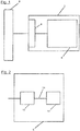
- Fig. 1 shows a test device 2, which is an HIL simulator 2 in the present case.
- the HIL simulator 2 has a physical interface 4, via which external devices can be connected to the HIL simulator 2.
- a control unit 8 is connected to the physical interface 4.
- Control unit 8 is an engine control unit that is set up to control the engine of a motor vehicle.
- the HIL simulator 2 is set up to test the engine control unit 8.
- the HIL simulator 2 includes a model 6 of a technical system.
- Model 6 is a model of a combination of an engine and a transmission.
- the model 6 is available as a software model and can exchange data with the physical interface 4. This results in a data connection between the controller 8 and the model 6, whereby the interaction of these two components can be simulated and tested.
- the physical interface 4 assumes the transition between the physical signals transmitted by and to the control unit and the logical, ie software-based, signals exchanged within the HIL simulator 2.
- the HIL simulator is real-time capable.
- the control unit 8 can be tested without further adaptation, that is to say in its configuration used later in operation.
- the HIL simulator 2 interacts in that speed with the control unit 8, which would have an objectively existing technical system, in the present case a combination of a real engine and transmission of a motor vehicle. This in turn means that the behavior of the model 6 is also calculated in at least this speed.
- Model 6 is an executable model, i. the model 6 is in a compiled form and can be executed on the hardware of the HIL simulator 2.
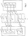
- Fig. 2 shows the model 6 of the technical system Fig. 1 in greater detail.
- the model 6 has two executable submodels 10 and 12, namely a first executable sub model 10 and a second executable sub model 12.
- the first Executable Part Model 10 is a model of the engine that is to be controlled by the engine control unit 8.
- the first executable model 10 is connected to the physical interface 4 and can communicate therewith with the control unit 8.
- the second executable sub-model 12 is a model of the transmission of the motor vehicle.
- the generation of the model 6 from the first executable sub-model 10 and the second executable sub-model 12 by establishing the real-time communication link 14 will be described in detail below.
- the first sub-model 10 and the second sub-model 12 are executed on separate processors during the simulation.
- the calculations for the first sub-model 10 and the second sub-model 12 can be carried out completely in parallel.
- the first sub-model 10 and the second sub-model 12 can be executed on the same processor but in separate processor cores.
- the first submodel 10 and the second submodel 12 can have different address spaces, executing on the same processor or on different processors.
- the model 6 is considered as a model of a technical system to be controlled. For this it is irrelevant that only the first executable sub-model 10 is controlled directly by the control unit 8.
- the control unit 8 has influence on the entirety of the combination of engine model and transmission model via the first executable partial model 10.
- the second executable submodel 12, i. the transmission model is a model of the environment of the engine and is therefore also referred to as environmental model. It is emphasized that the method described below for generating a model executable on a tester is applicable not only to technical systems to be controlled but to any type of executable models of technical systems running on a tester. It is irrelevant for the course of the process whether the executable models contain components to be controlled or not.
- Fig. 3 shows the first executable sub-model 10 and the second executable sub-model 12 in greater detail, with particular reference to the communication link 14 between the sub-models.
- the first executable sub-model 10 has a first conditionally executable component 100 and a second conditionally executable component 102.
- the first conditionally executable component 100 is a model of an internal combustion engine.
- the second conditionally executable component 102 is a model of an electric motor.
- the first executable sub-model 10 is a model of a hybrid engine.
- conditionally executable component refers to a subcomponent of an executable submodel.
- conditionally expresses that the model of the corresponding sub-component is executed only in certain operating situations, such as when the electric motor is switched on, or the behavior is calculated only for specific events or that the model otherwise depends on any conditions. In individual cases, it is also possible that a conditionally executed component is constantly executed. However, the term implies that the execution of the model of the respective components may be subject to one or more conditions.
- the first conditionally executable component 100 has a first variable 104 and a second variable 106.
- the first variable 104 is the speed of the internal combustion engine.
- the second variable 106 is the torque of the internal combustion engine.
- the second conditionally executable component 102 has a third variable 108.
- the third variable 108 is the additional torque of the electric motor.
- the first executable sub-model 10 has a first communication interface 110, a second communication interface 112 and a third communication interface 114. Via these communication interfaces, the first variable 104, the second variable 106 and the third variable 108 are transmitted to the second executable sub-model 12 during the simulation as described in detail below.
- the second executable submodel 12 has a third conditionally executable component 120.
- the third conditionally executable component 120 has a fourth variable 122, a fifth variable 124, and a sixth variable 126.
- the fourth variable 122 is the engine speed, which is the fifth variable 124 the torque of the engine, and the sixth variable 126 is the additional torque of the electric motor.
- the third constrained component 120 is a model of the transmission that models the behavior of the transmission based on the values for the variables obtained from the engine.
- the second executable submodel 12 has a fourth communication interface 128, a fifth communication interface 130, and a sixth communication interface 132 via which the data is received by the executable submodel 10 and forwarded to the third conditionally executable component 120.
- first data 146 is transmitted to the fourth communication interface 128, which is connected to the fourth variable 122.
- second data 148 are transmitted to the fifth communication interface 130, which is connected to the fifth variable 124.
- third data 150 are transmitted to the sixth communication interface 132, which is connected to the sixth variable 126.
- the first data 146 and the second data 148 come from the same conditionally executable component 100 and relate to the same time in the simulated time. Therefore, the first data 146 and the second data 148 are combined into a first consistency buffer 142.
- the third data 150 comes from another conditionally executable component, namely from the second conditionally executable component 102.
- the second conditionally executable component 102 which is a model of an electric motor, is executed only when the electric motor is engaged.
- third data 150 is not always available.
- the simulated time of the second conditionally executed constituent 102 is not exactly synchronized with the simulated time of the first conditionally executed constituent 100, or that the iteration steps of the constituent constituents 100, 102 are not performed equally often.
- the third data 150 is provided in its own second consistency buffer 144.
- This division into own consistency buffers expresses that perfect data consistency in the sense of real-time simulation between the two consistency buffers 142 and 144 is not necessarily present.
- consistency batches apply to data that is transmitted together and to the same Time of the simulated time belong.
- the first consistency buffer 142 and the second consistency buffer 144 are combined in a communication packet 140, which is transmitted from the first executable submodel 10 to the second executable submodel 12.
- the term communication packet refers to the transmission of a data unit which is transmitted by the first executable submodel 10 as a sender to the second executable submodel 12 as a receiver.
- the entirety of the formation of the data transmission is referred to as communication connection 14.
- the reception mode of the second executable submodel 12 is continuous, i. the second executable sub-model 12 receives all incoming data via the communication link 14.
- the third conditional component 120 processes the incoming data, whether or not they differ from previously received data. This makes sense in the present case, in particular, because it may be that no third data 150 is transmitted, but the first data 146 and the second data 148 change during the course of the simulation. Such a sustained reception is also described as "non-blocking" or asynchronously.
- there is also an event-driven receive mode in which the receiving executable sub-model responds only to changes in the transmitted data. Such a type of reception is also referred to as "blocking" or synchronous, because non-changing data is blocked by a conditionally executed component before being processed.
- the two executable submodels 10 and 12 can exchange many more data in addition to the data transfer described above. This data exchange can take place in both directions. Merely due to the clarity of the explanation of the communication link 14, the description has been limited to the three variables speed of the engine, torque of the engine and torque of the electric motor.
- FIG. 12 illustrates a method for generating the executable model 6 as described above according to an exemplary embodiment of the invention.
- Starting point of the method are the first executable submodel 10 and the second executable submodel 12.
- the two executable submodels are each associated with a metafile.
- the first executable sub-model 10 is associated with a first metafile 10a.
- the second executable submodel 12 is associated with a second metafile 12a.
- the first and the second metafile 10a, 12a contain descriptions of the communication properties of the first executable submodel 10 and of the second executable submodel 12.
- the first metafile 10a contains for each of the variables to be communicated the first executable submodel 10 the communication direction, the data type, the data width, and the assignment to a conditionally executable component of the first executable sub-model 10.
- the second meta-file 12a for each of the variables to be communicated includes the communication direction, the data type, the data width, and the assignment to a conditionally executable component of the second executable submodel 12.
- the metafiles 10a and 12a contain the information locally relevant to the submodels to provide communication between different submodels.
- the first metafile 10a and the second metafile 12a are coupled to communication definitions 16.
- the communication definitions 16 it is determined which submodels should communicate with each other, which data should be bundled in communication packets, and on which receive mode the data should be received.
- the communication definitions 16 are a file containing a description of the following information: the first executable sub-model 10 communicates with the second executable sub-model 12; all data to be transmitted from the first executable sub-model 10 to the second executable sub-model 12 is bundled in a communication packet; the second executable sub-model 12 continuously receives the data.
- mapping file 18 contains a description of the communication interfaces to be configured later and the communication connection to be established later between the submodels.
- the mapping file 18, also referred to as a mapping file, has a defined format that contains the entire information that will later be required for linking the two executable submodels 10, 12.
- a second processing step 22 from the first executable submodel 10, the second executable submodel 12, and the assignment file 18, the above-described model 6 is generated, which includes the first executable submodel 10, the second executable submodel 12, the respective communication interfaces, and the real-time communication link 14 contains.
- the information for configuring the communication interfaces and setting up the real-time communication link 14 comes from the mapping file 18.
- the communication between the first executable submodel 10 and the second executable submodel 12 proceeds as described above Fig. 3 described.
- the intermediate step via the mapping file 18 is optional. It is also possible that the model 6 is generated directly from the information of the first metafile 10a, the second metafile 12a and the communication definitions 16. Furthermore, the first metafile 10a and the second metafile 12a are but one of many ways in which the information regarding the variables to be communicated of the executable submodels may be provided. The combination of an executable submodel and a metafile associated therewith may be generated as part of compiling a high level language submodel.
- high-level sub-model here means that the sub-model is present in a high-level programming language.
- a high-level programming language - also known as a "higher-level programming language" - is a programming language for writing a computer program that is clearly removed from the level of machine languages in terms of abstraction and complexity. Examples of high-level programming languages are C, C ++, Java or even scripting languages such as Python, Javascript, M-Code (MATLAB-code) or graphical programming languages such as Simulink and Labview.
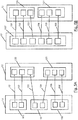
- Fig. 5 shows another example of the communication between two executable submodels.
- Fig. 5 illustrates how the late establishment of communication links between the submodels enables the exchange of already compiled, executable submodels. While Fig. 5A the situation before replacing an executable submodel is shown in Fig. 5B the situation after the replacement of the executable submodel shown.
- Fig. 5A 1 shows a first executable sub-model 10 and a second executable sub-model 12.
- the first executable sub-model 10 has a first conditionally-executable component 100, a second conditionally-executable component 101, and a third conditionally-executable component 102.
- the second executable sub-model 12 has a fourth conditionally-executable component Component 120 and a fifth conditionally executed component 121.
- first data 151 and second data 152 are transmitted to the fourth conditionally executed component 120.
- the first data 151 and the second data 152 are organized in a first consistency buffer.
- third data are transmitted to the fourth conditionally executed constituent 120.
- the third data 153 form a separate, second consistency buffer.
- the first consistency buffer and the second consistency buffer are transmitted together as a data packet.
- fourth data 154 are transmitted to the fifth conditionally executed component 121.
- the fourth data 154 form its own, third consistency buffer.
- fifth data 155 and sixth data 156 are transmitted to the fifth conditionally executed constituent 121.
- the fifth data 155 and sixth data 156 form a fourth consistency buffer.
- the third consistency buffer and the fourth consistency buffer are transmitted together in a second communication packet.
- the modified first executable submodel 10 ' is characterized in that it contains only a first conditionally executable component 100'.
- first data 151, the second data 152 and the third data 153 form a first consistency buffer
- fourth data 154, the fifth data 155 and the sixth data 156 form a second consistency buffer.
- the data of each consistency buffer is organized in a separate data package.
- the communication between the first executable sub-model 10 and the second executable sub-model 12, in particular the communication interfaces of the first executable sub-model 10 and the real-time communication link between the submodels, are constructed differently.
- the communication interfaces and the real-time-capable communication connection are adapted to the modified embodiment of the first executable sub-model 10.
- the method for generating an executable model according to exemplary embodiments of the invention allows the exchange of ready compiled, executable submodels, wherein the communication between different submodels is adapted thereto and a recompilation of the submodels is not required.
- the method of generating an executable model according to example embodiments of the invention enables a change in the desired communication using the communication definitions after compiling the partial models.
Landscapes
- Engineering & Computer Science (AREA)
- Physics & Mathematics (AREA)
- General Physics & Mathematics (AREA)
- Theoretical Computer Science (AREA)
- Geometry (AREA)
- General Engineering & Computer Science (AREA)
- Computer Hardware Design (AREA)
- Automation & Control Theory (AREA)
- Evolutionary Computation (AREA)
- Software Systems (AREA)
- Computational Mathematics (AREA)
- Mathematical Analysis (AREA)
- Mathematical Optimization (AREA)
- Pure & Applied Mathematics (AREA)
- Aviation & Aerospace Engineering (AREA)
- Microelectronics & Electronic Packaging (AREA)
- Debugging And Monitoring (AREA)
- Programmable Controllers (AREA)
Priority Applications (4)
| Application Number | Priority Date | Filing Date | Title |
|---|---|---|---|
| EP17188999.1A EP3451202B1 (fr) | 2017-09-01 | 2017-09-01 | Procédé de génération d'un modèle d'un système technique exécutable sur un appareil d'essai et appareil d'essai |
| DE102018110020.5A DE102018110020A1 (de) | 2017-09-01 | 2018-04-26 | Verfahren zum Erzeugen eines auf einem Testgerät ausführbaren Modells eines technischen Systems und Testgerät |
| US16/004,564 US11022967B2 (en) | 2017-09-01 | 2018-06-11 | Method for generating a technical system model, executable on a test unit, and the test unit |
| CN201810599858.2A CN109426158B (zh) | 2017-09-01 | 2018-06-12 | 用于生成在测试装置上可实施的模型的方法和测试装置 |
Applications Claiming Priority (1)
| Application Number | Priority Date | Filing Date | Title |
|---|---|---|---|
| EP17188999.1A EP3451202B1 (fr) | 2017-09-01 | 2017-09-01 | Procédé de génération d'un modèle d'un système technique exécutable sur un appareil d'essai et appareil d'essai |
Publications (2)
| Publication Number | Publication Date |
|---|---|
| EP3451202A1 true EP3451202A1 (fr) | 2019-03-06 |
| EP3451202B1 EP3451202B1 (fr) | 2021-02-24 |
Family
ID=59895042
Family Applications (1)
| Application Number | Title | Priority Date | Filing Date |
|---|---|---|---|
| EP17188999.1A Active EP3451202B1 (fr) | 2017-09-01 | 2017-09-01 | Procédé de génération d'un modèle d'un système technique exécutable sur un appareil d'essai et appareil d'essai |
Country Status (4)
| Country | Link |
|---|---|
| US (1) | US11022967B2 (fr) |
| EP (1) | EP3451202B1 (fr) |
| CN (1) | CN109426158B (fr) |
| DE (1) | DE102018110020A1 (fr) |
Cited By (1)
| Publication number | Priority date | Publication date | Assignee | Title |
|---|---|---|---|---|
| CN114035447A (zh) * | 2021-10-20 | 2022-02-11 | 华南师范大学 | 用于中小学人工智能教育图形化编程软件的硬件仿真器 |
Families Citing this family (5)
| Publication number | Priority date | Publication date | Assignee | Title |
|---|---|---|---|---|
| EP3502817A1 (fr) * | 2017-12-19 | 2019-06-26 | ABB Schweiz AG | Procédé pour faciliter les essais et la simulation de système de commande |
| CN110658739B (zh) * | 2019-10-09 | 2022-12-13 | 上海宽射科技有限公司 | 一种半实物仿真电机控制及电力电子实验装置及实验控制方法 |
| DE102020131260A1 (de) | 2020-11-25 | 2022-05-25 | AVL SET GmbH | Verfahren zur Durchführung eines Prüflaufs mit einem Prüfling |
| CN118234581A (zh) | 2021-11-25 | 2024-06-21 | 林德有限责任公司 | 用于制造部件的方法以及相应制造的部件 |
| WO2025190899A1 (fr) * | 2024-03-12 | 2025-09-18 | Dspace Gmbh | Procédé mis en œuvre par ordinateur pour tester un dispositif de commande électronique avec un simulateur et simulateur correspondant |
Citations (4)
| Publication number | Priority date | Publication date | Assignee | Title |
|---|---|---|---|---|
| US20040078180A1 (en) * | 2002-10-16 | 2004-04-22 | Allen Richard Craig | Method for automatically decomposing dynamic system models into submodels |
| EP1489531A1 (fr) * | 2003-06-20 | 2004-12-22 | Robert Bosch Gmbh | Système de simulation et mèthode assistée par ordinateur pour la simulation et la vèrification d'un système de commandes |
| DE102011101920A1 (de) * | 2010-05-24 | 2011-11-24 | Gm Global Technology Operations Llc (N.D.Ges.D. Staates Delaware) | Fahrzeugsystemmodellerstellungssysteme und -verfahren |
| DE102012108490A1 (de) * | 2012-09-11 | 2014-03-13 | SimX GmbH | Verfahren und Simulationsumgebung zur flexiblen automatisierten Verbindung von Teilmodellen |
Family Cites Families (13)
| Publication number | Priority date | Publication date | Assignee | Title |
|---|---|---|---|---|
| US20050028133A1 (en) * | 2003-08-02 | 2005-02-03 | Viswanath Ananth | System and method for rapid design, prototyping, and implementation of distributed scalable architecture for task control and automation |
| US8798972B2 (en) * | 2008-06-26 | 2014-08-05 | The Boeing Company | Apparatus and method for virtual assembly, integration and testing of an integrated system |
| CN101504690B (zh) * | 2009-03-26 | 2011-04-13 | 北京航空航天大学 | 用于通信系统集成电路设计的实时仿真验证系统及其方法 |
| US8321187B2 (en) * | 2009-04-24 | 2012-11-27 | Rockwell Automation Technologies, Inc. | Process simulation utilizing component-specific consumption data |
| US10037443B2 (en) * | 2011-03-07 | 2018-07-31 | Rockwell Automation Technologies, Inc. | Industrial simulation using redirected I/O module configurations |
| CN102520711B (zh) * | 2011-11-28 | 2014-07-02 | 联合汽车电子有限公司 | Amt控制器的硬件在环仿真系统及其自动测试方法 |
| US9529348B2 (en) * | 2012-01-24 | 2016-12-27 | Emerson Process Management Power & Water Solutions, Inc. | Method and apparatus for deploying industrial plant simulators using cloud computing technologies |
| EP2990892B1 (fr) * | 2014-09-01 | 2019-05-22 | dSPACE digital signal processing and control engineering GmbH | Procédé de liaison d'une interface d'entrée/de sortie d'un appareil d'essai destiné à l'essai d'un appareil de commande |
| EP3130970A1 (fr) * | 2015-08-12 | 2017-02-15 | dSPACE digital signal processing and control engineering GmbH | Procede de liaison d'une interface d'entree/de sortie d'un appareil d'essai destine a la mise au point d'appareil de commande |
| US10386806B2 (en) * | 2015-09-01 | 2019-08-20 | Dspace Digital Signal Processing And Control Engineering Gmbh | Method for connecting models of technical systems in a testing device equipped for control unit development |
| DE102016102920A1 (de) * | 2016-02-19 | 2017-08-24 | Dspace Digital Signal Processing And Control Engineering Gmbh | Verfahren zur Konfiguration eines zum Testen eines elektronischen Steuergeräts eingerichteten Testgeräts |
| US10315520B2 (en) * | 2017-04-04 | 2019-06-11 | Southwest University | Apparatuses and methods of an in-vehicle gateway system for monitoring and controling in-vehicle subsystems |
| US11216604B2 (en) * | 2017-06-02 | 2022-01-04 | The Mathworks, Inc. | Systems and methods for co-simulation |
-
2017
- 2017-09-01 EP EP17188999.1A patent/EP3451202B1/fr active Active
-
2018
- 2018-04-26 DE DE102018110020.5A patent/DE102018110020A1/de not_active Withdrawn
- 2018-06-11 US US16/004,564 patent/US11022967B2/en active Active
- 2018-06-12 CN CN201810599858.2A patent/CN109426158B/zh active Active
Patent Citations (4)
| Publication number | Priority date | Publication date | Assignee | Title |
|---|---|---|---|---|
| US20040078180A1 (en) * | 2002-10-16 | 2004-04-22 | Allen Richard Craig | Method for automatically decomposing dynamic system models into submodels |
| EP1489531A1 (fr) * | 2003-06-20 | 2004-12-22 | Robert Bosch Gmbh | Système de simulation et mèthode assistée par ordinateur pour la simulation et la vèrification d'un système de commandes |
| DE102011101920A1 (de) * | 2010-05-24 | 2011-11-24 | Gm Global Technology Operations Llc (N.D.Ges.D. Staates Delaware) | Fahrzeugsystemmodellerstellungssysteme und -verfahren |
| DE102012108490A1 (de) * | 2012-09-11 | 2014-03-13 | SimX GmbH | Verfahren und Simulationsumgebung zur flexiblen automatisierten Verbindung von Teilmodellen |
Cited By (2)
| Publication number | Priority date | Publication date | Assignee | Title |
|---|---|---|---|---|
| CN114035447A (zh) * | 2021-10-20 | 2022-02-11 | 华南师范大学 | 用于中小学人工智能教育图形化编程软件的硬件仿真器 |
| CN114035447B (zh) * | 2021-10-20 | 2022-05-31 | 华南师范大学 | 用于中小学人工智能教育图形化编程软件的硬件仿真器 |
Also Published As
| Publication number | Publication date |
|---|---|
| CN109426158A (zh) | 2019-03-05 |
| DE102018110020A1 (de) | 2019-03-07 |
| EP3451202B1 (fr) | 2021-02-24 |
| US11022967B2 (en) | 2021-06-01 |
| CN109426158B (zh) | 2023-10-13 |
| US20190072946A1 (en) | 2019-03-07 |
Similar Documents
| Publication | Publication Date | Title |
|---|---|---|
| EP3451202B1 (fr) | Procédé de génération d'un modèle d'un système technique exécutable sur un appareil d'essai et appareil d'essai | |
| EP2685382B1 (fr) | Procédé et dispositif de création et de test d'un programme d'appareil de commande | |
| DE102014110096A1 (de) | Testeinrichtung zum Echtzeittest eines virtuellen Steuergeräts | |
| EP3336730B1 (fr) | Procédé de réalisation d'un modèle compatible avec un simulateur | |
| EP3306295B1 (fr) | Procédé et dispositif d'essai de commandes électroniques, en particulier d'essai de commandes automobiles | |
| DE102015207656A1 (de) | Verfahren und System zum Testen von Steuersoftware eines gesteuerten Systems | |
| EP3001313A1 (fr) | Procédé de simulation d'un programme d'application d'un appareil de commande électronique sur un ordinateur | |
| DE102017120016A1 (de) | Verfahren zur Konfiguration eines zum Testen eines elektronischen Steuergeräts eingerichteten Testgeräts sowie Konfigurationssystem | |
| EP1906377A1 (fr) | Système et procédé d'intégration d'un système de contrôle de processus industriel dans un simulateur d'entraînement | |
| EP3130970A1 (fr) | Procede de liaison d'une interface d'entree/de sortie d'un appareil d'essai destine a la mise au point d'appareil de commande | |
| DE102016119320A1 (de) | Verfahren zum Konfigurieren eines realen oder virtuellen elektronischen Steuergerätes | |
| DE102005026040A1 (de) | Parametrierung eines Simulations-Arbeitsmodells | |
| EP3398092A1 (fr) | Procédé de configuration d'une cosimulation pour un système complet | |
| DE102018110018A1 (de) | Verfahren zum Bereitstellen eines integrierten Prozesses für die Steuergerätentwicklung und Simulationsvorrichtung für die Steuergerätentwicklung | |
| DE102020123506A1 (de) | Verfahren zur Erzeugung von Quellcode mit servicebasierter Kommunikation | |
| WO2025021439A1 (fr) | Plateforme de simulation et procédé de configuration de simulateurs en temps réel et non en temps réel pour mettre en œuvre différents programmes de simulation dans un environnement de simulation commun à l'aide de la plateforme de simulation | |
| DE10324594A1 (de) | Verfahren zum Bereitstellen einer verbesserten Simulationsfähigkeit eines dynamischen Systems außerhalb der ursprünglichen Modellierungsumgebung | |
| EP2083339A1 (fr) | Dispositif et procédé destinés à l'exécution de tests à l'aide de dispositifs de test et d'expérimentation cascadés fonctionnellement | |
| DE102010009994A1 (de) | Verfahren zur Optimierung eines Steuerungsprogramms für Aktuatoren | |
| DE102016101344A1 (de) | Verfahren zur Konfiguration eines für das Testen eines Steuergeräts eingerichteten Testgeräts | |
| DE102018206762A1 (de) | Feature-Development-Framework und Feature-Integration-Framework zum Implementieren physikalischer Funktionsfeatures in einem Zielgerät | |
| EP2672660B1 (fr) | Méthode pur influencer le communication de bus d'un bloc de contrôle électronique | |
| EP4199553A1 (fr) | Procédé et unité d'essai destiné à la mise en uvre d'essais virtuels | |
| EP1936452A1 (fr) | Procédé et dispositif destinés au traitement dynamique d'objets d'un modèle de simulation | |
| DE102009054137A1 (de) | Verfahren zum Testen einer Applikation hinsichtlich ihrer Performanz |
Legal Events
| Date | Code | Title | Description |
|---|---|---|---|
| PUAI | Public reference made under article 153(3) epc to a published international application that has entered the european phase |
Free format text: ORIGINAL CODE: 0009012 |
|
| STAA | Information on the status of an ep patent application or granted ep patent |
Free format text: STATUS: THE APPLICATION HAS BEEN PUBLISHED |
|
| AK | Designated contracting states |
Kind code of ref document: A1 Designated state(s): AL AT BE BG CH CY CZ DE DK EE ES FI FR GB GR HR HU IE IS IT LI LT LU LV MC MK MT NL NO PL PT RO RS SE SI SK SM TR |
|
| AX | Request for extension of the european patent |
Extension state: BA ME |
|
| STAA | Information on the status of an ep patent application or granted ep patent |
Free format text: STATUS: REQUEST FOR EXAMINATION WAS MADE |
|
| 17P | Request for examination filed |
Effective date: 20190906 |
|
| RBV | Designated contracting states (corrected) |
Designated state(s): AL AT BE BG CH CY CZ DE DK EE ES FI FR GB GR HR HU IE IS IT LI LT LU LV MC MK MT NL NO PL PT RO RS SE SI SK SM TR |
|
| REG | Reference to a national code |
Ref country code: DE Ref legal event code: R079 Ref document number: 502017009446 Country of ref document: DE Free format text: PREVIOUS MAIN CLASS: G06F0017500000 Ipc: G06F0008350000 |
|
| GRAP | Despatch of communication of intention to grant a patent |
Free format text: ORIGINAL CODE: EPIDOSNIGR1 |
|
| STAA | Information on the status of an ep patent application or granted ep patent |
Free format text: STATUS: GRANT OF PATENT IS INTENDED |
|
| RIC1 | Information provided on ipc code assigned before grant |
Ipc: G06F 30/20 20200101ALI20201020BHEP Ipc: G06F 9/54 20060101ALI20201020BHEP Ipc: G06F 8/41 20180101ALI20201020BHEP Ipc: G05B 17/02 20060101ALI20201020BHEP Ipc: G06F 30/15 20200101ALI20201020BHEP Ipc: G06F 117/08 20200101ALI20201020BHEP Ipc: G05B 17/00 20060101ALI20201020BHEP Ipc: G06F 8/35 20180101AFI20201020BHEP |
|
| INTG | Intention to grant announced |
Effective date: 20201106 |
|
| GRAS | Grant fee paid |
Free format text: ORIGINAL CODE: EPIDOSNIGR3 |
|
| GRAA | (expected) grant |
Free format text: ORIGINAL CODE: 0009210 |
|
| STAA | Information on the status of an ep patent application or granted ep patent |
Free format text: STATUS: THE PATENT HAS BEEN GRANTED |
|
| AK | Designated contracting states |
Kind code of ref document: B1 Designated state(s): AL AT BE BG CH CY CZ DE DK EE ES FI FR GB GR HR HU IE IS IT LI LT LU LV MC MK MT NL NO PL PT RO RS SE SI SK SM TR |
|
| REG | Reference to a national code |
Ref country code: CH Ref legal event code: EP |
|
| REG | Reference to a national code |
Ref country code: AT Ref legal event code: REF Ref document number: 1365329 Country of ref document: AT Kind code of ref document: T Effective date: 20210315 |
|
| REG | Reference to a national code |
Ref country code: IE Ref legal event code: FG4D Free format text: LANGUAGE OF EP DOCUMENT: GERMAN |
|
| REG | Reference to a national code |
Ref country code: DE Ref legal event code: R096 Ref document number: 502017009446 Country of ref document: DE |
|
| REG | Reference to a national code |
Ref country code: LT Ref legal event code: MG9D |
|
| REG | Reference to a national code |
Ref country code: NL Ref legal event code: MP Effective date: 20210224 |
|
| PG25 | Lapsed in a contracting state [announced via postgrant information from national office to epo] |
Ref country code: HR Free format text: LAPSE BECAUSE OF FAILURE TO SUBMIT A TRANSLATION OF THE DESCRIPTION OR TO PAY THE FEE WITHIN THE PRESCRIBED TIME-LIMIT Effective date: 20210224 Ref country code: FI Free format text: LAPSE BECAUSE OF FAILURE TO SUBMIT A TRANSLATION OF THE DESCRIPTION OR TO PAY THE FEE WITHIN THE PRESCRIBED TIME-LIMIT Effective date: 20210224 Ref country code: GR Free format text: LAPSE BECAUSE OF FAILURE TO SUBMIT A TRANSLATION OF THE DESCRIPTION OR TO PAY THE FEE WITHIN THE PRESCRIBED TIME-LIMIT Effective date: 20210525 Ref country code: PT Free format text: LAPSE BECAUSE OF FAILURE TO SUBMIT A TRANSLATION OF THE DESCRIPTION OR TO PAY THE FEE WITHIN THE PRESCRIBED TIME-LIMIT Effective date: 20210624 Ref country code: NO Free format text: LAPSE BECAUSE OF FAILURE TO SUBMIT A TRANSLATION OF THE DESCRIPTION OR TO PAY THE FEE WITHIN THE PRESCRIBED TIME-LIMIT Effective date: 20210524 Ref country code: LT Free format text: LAPSE BECAUSE OF FAILURE TO SUBMIT A TRANSLATION OF THE DESCRIPTION OR TO PAY THE FEE WITHIN THE PRESCRIBED TIME-LIMIT Effective date: 20210224 Ref country code: BG Free format text: LAPSE BECAUSE OF FAILURE TO SUBMIT A TRANSLATION OF THE DESCRIPTION OR TO PAY THE FEE WITHIN THE PRESCRIBED TIME-LIMIT Effective date: 20210524 |
|
| PG25 | Lapsed in a contracting state [announced via postgrant information from national office to epo] |
Ref country code: RS Free format text: LAPSE BECAUSE OF FAILURE TO SUBMIT A TRANSLATION OF THE DESCRIPTION OR TO PAY THE FEE WITHIN THE PRESCRIBED TIME-LIMIT Effective date: 20210224 Ref country code: LV Free format text: LAPSE BECAUSE OF FAILURE TO SUBMIT A TRANSLATION OF THE DESCRIPTION OR TO PAY THE FEE WITHIN THE PRESCRIBED TIME-LIMIT Effective date: 20210224 Ref country code: NL Free format text: LAPSE BECAUSE OF FAILURE TO SUBMIT A TRANSLATION OF THE DESCRIPTION OR TO PAY THE FEE WITHIN THE PRESCRIBED TIME-LIMIT Effective date: 20210224 Ref country code: PL Free format text: LAPSE BECAUSE OF FAILURE TO SUBMIT A TRANSLATION OF THE DESCRIPTION OR TO PAY THE FEE WITHIN THE PRESCRIBED TIME-LIMIT Effective date: 20210224 Ref country code: SE Free format text: LAPSE BECAUSE OF FAILURE TO SUBMIT A TRANSLATION OF THE DESCRIPTION OR TO PAY THE FEE WITHIN THE PRESCRIBED TIME-LIMIT Effective date: 20210224 |
|
| PG25 | Lapsed in a contracting state [announced via postgrant information from national office to epo] |
Ref country code: IS Free format text: LAPSE BECAUSE OF FAILURE TO SUBMIT A TRANSLATION OF THE DESCRIPTION OR TO PAY THE FEE WITHIN THE PRESCRIBED TIME-LIMIT Effective date: 20210624 |
|
| PG25 | Lapsed in a contracting state [announced via postgrant information from national office to epo] |
Ref country code: SM Free format text: LAPSE BECAUSE OF FAILURE TO SUBMIT A TRANSLATION OF THE DESCRIPTION OR TO PAY THE FEE WITHIN THE PRESCRIBED TIME-LIMIT Effective date: 20210224 Ref country code: CZ Free format text: LAPSE BECAUSE OF FAILURE TO SUBMIT A TRANSLATION OF THE DESCRIPTION OR TO PAY THE FEE WITHIN THE PRESCRIBED TIME-LIMIT Effective date: 20210224 Ref country code: EE Free format text: LAPSE BECAUSE OF FAILURE TO SUBMIT A TRANSLATION OF THE DESCRIPTION OR TO PAY THE FEE WITHIN THE PRESCRIBED TIME-LIMIT Effective date: 20210224 |
|
| REG | Reference to a national code |
Ref country code: DE Ref legal event code: R097 Ref document number: 502017009446 Country of ref document: DE |
|
| PG25 | Lapsed in a contracting state [announced via postgrant information from national office to epo] |
Ref country code: DK Free format text: LAPSE BECAUSE OF FAILURE TO SUBMIT A TRANSLATION OF THE DESCRIPTION OR TO PAY THE FEE WITHIN THE PRESCRIBED TIME-LIMIT Effective date: 20210224 Ref country code: RO Free format text: LAPSE BECAUSE OF FAILURE TO SUBMIT A TRANSLATION OF THE DESCRIPTION OR TO PAY THE FEE WITHIN THE PRESCRIBED TIME-LIMIT Effective date: 20210224 Ref country code: SK Free format text: LAPSE BECAUSE OF FAILURE TO SUBMIT A TRANSLATION OF THE DESCRIPTION OR TO PAY THE FEE WITHIN THE PRESCRIBED TIME-LIMIT Effective date: 20210224 |
|
| PLBE | No opposition filed within time limit |
Free format text: ORIGINAL CODE: 0009261 |
|
| STAA | Information on the status of an ep patent application or granted ep patent |
Free format text: STATUS: NO OPPOSITION FILED WITHIN TIME LIMIT |
|
| REG | Reference to a national code |
Ref country code: DE Ref legal event code: R081 Ref document number: 502017009446 Country of ref document: DE Owner name: DSPACE GMBH, DE Free format text: FORMER OWNER: DSPACE DIGITAL SIGNAL PROCESSING AND CONTROL ENGINEERING GMBH, 33102 PADERBORN, DE Ref country code: DE Ref legal event code: R081 Ref document number: 502017009446 Country of ref document: DE Owner name: DSPACE SE & CO KG, DE Free format text: FORMER OWNER: DSPACE DIGITAL SIGNAL PROCESSING AND CONTROL ENGINEERING GMBH, 33102 PADERBORN, DE |
|
| RAP4 | Party data changed (patent owner data changed or rights of a patent transferred) |
Owner name: DSPACE GMBH |
|
| PG25 | Lapsed in a contracting state [announced via postgrant information from national office to epo] |
Ref country code: AL Free format text: LAPSE BECAUSE OF FAILURE TO SUBMIT A TRANSLATION OF THE DESCRIPTION OR TO PAY THE FEE WITHIN THE PRESCRIBED TIME-LIMIT Effective date: 20210224 Ref country code: ES Free format text: LAPSE BECAUSE OF FAILURE TO SUBMIT A TRANSLATION OF THE DESCRIPTION OR TO PAY THE FEE WITHIN THE PRESCRIBED TIME-LIMIT Effective date: 20210224 |
|
| 26N | No opposition filed |
Effective date: 20211125 |
|
| PG25 | Lapsed in a contracting state [announced via postgrant information from national office to epo] |
Ref country code: SI Free format text: LAPSE BECAUSE OF FAILURE TO SUBMIT A TRANSLATION OF THE DESCRIPTION OR TO PAY THE FEE WITHIN THE PRESCRIBED TIME-LIMIT Effective date: 20210224 |
|
| PG25 | Lapsed in a contracting state [announced via postgrant information from national office to epo] |
Ref country code: IT Free format text: LAPSE BECAUSE OF FAILURE TO SUBMIT A TRANSLATION OF THE DESCRIPTION OR TO PAY THE FEE WITHIN THE PRESCRIBED TIME-LIMIT Effective date: 20210224 |
|
| REG | Reference to a national code |
Ref country code: CH Ref legal event code: PL |
|
| REG | Reference to a national code |
Ref country code: BE Ref legal event code: MM Effective date: 20210930 |
|
| GBPC | Gb: european patent ceased through non-payment of renewal fee |
Effective date: 20210901 |
|
| PG25 | Lapsed in a contracting state [announced via postgrant information from national office to epo] |
Ref country code: IS Free format text: LAPSE BECAUSE OF FAILURE TO SUBMIT A TRANSLATION OF THE DESCRIPTION OR TO PAY THE FEE WITHIN THE PRESCRIBED TIME-LIMIT Effective date: 20210624 Ref country code: MC Free format text: LAPSE BECAUSE OF FAILURE TO SUBMIT A TRANSLATION OF THE DESCRIPTION OR TO PAY THE FEE WITHIN THE PRESCRIBED TIME-LIMIT Effective date: 20210224 |
|
| PG25 | Lapsed in a contracting state [announced via postgrant information from national office to epo] |
Ref country code: LU Free format text: LAPSE BECAUSE OF NON-PAYMENT OF DUE FEES Effective date: 20210901 Ref country code: IE Free format text: LAPSE BECAUSE OF NON-PAYMENT OF DUE FEES Effective date: 20210901 Ref country code: GB Free format text: LAPSE BECAUSE OF NON-PAYMENT OF DUE FEES Effective date: 20210901 Ref country code: FR Free format text: LAPSE BECAUSE OF NON-PAYMENT OF DUE FEES Effective date: 20210930 Ref country code: BE Free format text: LAPSE BECAUSE OF NON-PAYMENT OF DUE FEES Effective date: 20210930 |
|
| PG25 | Lapsed in a contracting state [announced via postgrant information from national office to epo] |
Ref country code: LI Free format text: LAPSE BECAUSE OF NON-PAYMENT OF DUE FEES Effective date: 20210930 Ref country code: CH Free format text: LAPSE BECAUSE OF NON-PAYMENT OF DUE FEES Effective date: 20210930 |
|
| PG25 | Lapsed in a contracting state [announced via postgrant information from national office to epo] |
Ref country code: CY Free format text: LAPSE BECAUSE OF FAILURE TO SUBMIT A TRANSLATION OF THE DESCRIPTION OR TO PAY THE FEE WITHIN THE PRESCRIBED TIME-LIMIT Effective date: 20210224 |
|
| P01 | Opt-out of the competence of the unified patent court (upc) registered |
Effective date: 20230525 |
|
| PG25 | Lapsed in a contracting state [announced via postgrant information from national office to epo] |
Ref country code: HU Free format text: LAPSE BECAUSE OF FAILURE TO SUBMIT A TRANSLATION OF THE DESCRIPTION OR TO PAY THE FEE WITHIN THE PRESCRIBED TIME-LIMIT; INVALID AB INITIO Effective date: 20170901 |
|
| REG | Reference to a national code |
Ref country code: AT Ref legal event code: MM01 Ref document number: 1365329 Country of ref document: AT Kind code of ref document: T Effective date: 20220901 |
|
| PG25 | Lapsed in a contracting state [announced via postgrant information from national office to epo] |
Ref country code: AT Free format text: LAPSE BECAUSE OF NON-PAYMENT OF DUE FEES Effective date: 20220901 |
|
| PG25 | Lapsed in a contracting state [announced via postgrant information from national office to epo] |
Ref country code: MK Free format text: LAPSE BECAUSE OF FAILURE TO SUBMIT A TRANSLATION OF THE DESCRIPTION OR TO PAY THE FEE WITHIN THE PRESCRIBED TIME-LIMIT Effective date: 20210224 |
|
| PG25 | Lapsed in a contracting state [announced via postgrant information from national office to epo] |
Ref country code: MT Free format text: LAPSE BECAUSE OF FAILURE TO SUBMIT A TRANSLATION OF THE DESCRIPTION OR TO PAY THE FEE WITHIN THE PRESCRIBED TIME-LIMIT Effective date: 20210224 |
|
| PGFP | Annual fee paid to national office [announced via postgrant information from national office to epo] |
Ref country code: DE Payment date: 20250919 Year of fee payment: 9 |
|
| PG25 | Lapsed in a contracting state [announced via postgrant information from national office to epo] |
Ref country code: TR Free format text: LAPSE BECAUSE OF FAILURE TO SUBMIT A TRANSLATION OF THE DESCRIPTION OR TO PAY THE FEE WITHIN THE PRESCRIBED TIME-LIMIT Effective date: 20210224 |
|
| REG | Reference to a national code |
Ref country code: DE Ref legal event code: R081 Ref document number: 502017009446 Country of ref document: DE Owner name: DSPACE SE & CO KG, DE Free format text: FORMER OWNER: DSPACE GMBH, 33102 PADERBORN, DE |