EP3453602A1 - Dispositif de freinage à différence de temps de type hydraulique et ensemble associé - Google Patents
Dispositif de freinage à différence de temps de type hydraulique et ensemble associé Download PDFInfo
- Publication number
- EP3453602A1 EP3453602A1 EP16900802.6A EP16900802A EP3453602A1 EP 3453602 A1 EP3453602 A1 EP 3453602A1 EP 16900802 A EP16900802 A EP 16900802A EP 3453602 A1 EP3453602 A1 EP 3453602A1
- Authority
- EP
- European Patent Office
- Prior art keywords
- chamber
- piston
- pushing block
- brake
- time difference
- Prior art date
- Legal status (The legal status is an assumption and is not a legal conclusion. Google has not performed a legal analysis and makes no representation as to the accuracy of the status listed.)
- Granted
Links
Images


Classifications
-
- B—PERFORMING OPERATIONS; TRANSPORTING
- B60—VEHICLES IN GENERAL
- B60T—VEHICLE BRAKE CONTROL SYSTEMS OR PARTS THEREOF; BRAKE CONTROL SYSTEMS OR PARTS THEREOF, IN GENERAL; ARRANGEMENT OF BRAKING ELEMENTS ON VEHICLES IN GENERAL; PORTABLE DEVICES FOR PREVENTING UNWANTED MOVEMENT OF VEHICLES; VEHICLE MODIFICATIONS TO FACILITATE COOLING OF BRAKES
- B60T13/00—Transmitting braking action from initiating means to ultimate brake actuator with power assistance or drive; Brake systems incorporating such transmitting means, e.g. air-pressure brake systems
- B60T13/10—Transmitting braking action from initiating means to ultimate brake actuator with power assistance or drive; Brake systems incorporating such transmitting means, e.g. air-pressure brake systems with fluid assistance, drive, or release
- B60T13/12—Transmitting braking action from initiating means to ultimate brake actuator with power assistance or drive; Brake systems incorporating such transmitting means, e.g. air-pressure brake systems with fluid assistance, drive, or release the fluid being liquid
- B60T13/14—Transmitting braking action from initiating means to ultimate brake actuator with power assistance or drive; Brake systems incorporating such transmitting means, e.g. air-pressure brake systems with fluid assistance, drive, or release the fluid being liquid using accumulators or reservoirs fed by pumps
-
- B—PERFORMING OPERATIONS; TRANSPORTING
- B60—VEHICLES IN GENERAL
- B60T—VEHICLE BRAKE CONTROL SYSTEMS OR PARTS THEREOF; BRAKE CONTROL SYSTEMS OR PARTS THEREOF, IN GENERAL; ARRANGEMENT OF BRAKING ELEMENTS ON VEHICLES IN GENERAL; PORTABLE DEVICES FOR PREVENTING UNWANTED MOVEMENT OF VEHICLES; VEHICLE MODIFICATIONS TO FACILITATE COOLING OF BRAKES
- B60T11/00—Transmitting braking action from initiating means to ultimate brake actuator without power assistance or drive or where such assistance or drive is irrelevant
- B60T11/10—Transmitting braking action from initiating means to ultimate brake actuator without power assistance or drive or where such assistance or drive is irrelevant transmitting by fluid means, e.g. hydraulic
- B60T11/101—Transmitting braking action from initiating means to ultimate brake actuator without power assistance or drive or where such assistance or drive is irrelevant transmitting by fluid means, e.g. hydraulic equalising arrangements
-
- B—PERFORMING OPERATIONS; TRANSPORTING
- B60—VEHICLES IN GENERAL
- B60T—VEHICLE BRAKE CONTROL SYSTEMS OR PARTS THEREOF; BRAKE CONTROL SYSTEMS OR PARTS THEREOF, IN GENERAL; ARRANGEMENT OF BRAKING ELEMENTS ON VEHICLES IN GENERAL; PORTABLE DEVICES FOR PREVENTING UNWANTED MOVEMENT OF VEHICLES; VEHICLE MODIFICATIONS TO FACILITATE COOLING OF BRAKES
- B60T11/00—Transmitting braking action from initiating means to ultimate brake actuator without power assistance or drive or where such assistance or drive is irrelevant
- B60T11/04—Transmitting braking action from initiating means to ultimate brake actuator without power assistance or drive or where such assistance or drive is irrelevant transmitting mechanically
- B60T11/046—Using cables
-
- B—PERFORMING OPERATIONS; TRANSPORTING
- B60—VEHICLES IN GENERAL
- B60T—VEHICLE BRAKE CONTROL SYSTEMS OR PARTS THEREOF; BRAKE CONTROL SYSTEMS OR PARTS THEREOF, IN GENERAL; ARRANGEMENT OF BRAKING ELEMENTS ON VEHICLES IN GENERAL; PORTABLE DEVICES FOR PREVENTING UNWANTED MOVEMENT OF VEHICLES; VEHICLE MODIFICATIONS TO FACILITATE COOLING OF BRAKES
- B60T11/00—Transmitting braking action from initiating means to ultimate brake actuator without power assistance or drive or where such assistance or drive is irrelevant
- B60T11/10—Transmitting braking action from initiating means to ultimate brake actuator without power assistance or drive or where such assistance or drive is irrelevant transmitting by fluid means, e.g. hydraulic
- B60T11/16—Master control, e.g. master cylinders
- B60T11/224—Master control, e.g. master cylinders with pressure-varying means, e.g. with two stage operation provided by use of different piston diameters including continuous variation from one diameter to another
-
- B—PERFORMING OPERATIONS; TRANSPORTING
- B60—VEHICLES IN GENERAL
- B60T—VEHICLE BRAKE CONTROL SYSTEMS OR PARTS THEREOF; BRAKE CONTROL SYSTEMS OR PARTS THEREOF, IN GENERAL; ARRANGEMENT OF BRAKING ELEMENTS ON VEHICLES IN GENERAL; PORTABLE DEVICES FOR PREVENTING UNWANTED MOVEMENT OF VEHICLES; VEHICLE MODIFICATIONS TO FACILITATE COOLING OF BRAKES
- B60T13/00—Transmitting braking action from initiating means to ultimate brake actuator with power assistance or drive; Brake systems incorporating such transmitting means, e.g. air-pressure brake systems
- B60T13/10—Transmitting braking action from initiating means to ultimate brake actuator with power assistance or drive; Brake systems incorporating such transmitting means, e.g. air-pressure brake systems with fluid assistance, drive, or release
- B60T13/66—Electrical control in fluid-pressure brake systems
- B60T13/68—Electrical control in fluid-pressure brake systems by electrically-controlled valves
- B60T13/686—Electrical control in fluid-pressure brake systems by electrically-controlled valves in hydraulic systems or parts thereof
-
- B—PERFORMING OPERATIONS; TRANSPORTING
- B60—VEHICLES IN GENERAL
- B60T—VEHICLE BRAKE CONTROL SYSTEMS OR PARTS THEREOF; BRAKE CONTROL SYSTEMS OR PARTS THEREOF, IN GENERAL; ARRANGEMENT OF BRAKING ELEMENTS ON VEHICLES IN GENERAL; PORTABLE DEVICES FOR PREVENTING UNWANTED MOVEMENT OF VEHICLES; VEHICLE MODIFICATIONS TO FACILITATE COOLING OF BRAKES
- B60T17/00—Component parts, details, or accessories of power brake systems not covered by groups B60T8/00, B60T13/00 or B60T15/00, or presenting other characteristic features
- B60T17/02—Arrangements of pumps or compressors, or control devices therefor
-
- B—PERFORMING OPERATIONS; TRANSPORTING
- B60—VEHICLES IN GENERAL
- B60T—VEHICLE BRAKE CONTROL SYSTEMS OR PARTS THEREOF; BRAKE CONTROL SYSTEMS OR PARTS THEREOF, IN GENERAL; ARRANGEMENT OF BRAKING ELEMENTS ON VEHICLES IN GENERAL; PORTABLE DEVICES FOR PREVENTING UNWANTED MOVEMENT OF VEHICLES; VEHICLE MODIFICATIONS TO FACILITATE COOLING OF BRAKES
- B60T17/00—Component parts, details, or accessories of power brake systems not covered by groups B60T8/00, B60T13/00 or B60T15/00, or presenting other characteristic features
- B60T17/18—Safety devices; Monitoring
-
- B—PERFORMING OPERATIONS; TRANSPORTING
- B60—VEHICLES IN GENERAL
- B60T—VEHICLE BRAKE CONTROL SYSTEMS OR PARTS THEREOF; BRAKE CONTROL SYSTEMS OR PARTS THEREOF, IN GENERAL; ARRANGEMENT OF BRAKING ELEMENTS ON VEHICLES IN GENERAL; PORTABLE DEVICES FOR PREVENTING UNWANTED MOVEMENT OF VEHICLES; VEHICLE MODIFICATIONS TO FACILITATE COOLING OF BRAKES
- B60T7/00—Brake-action initiating means
- B60T7/02—Brake-action initiating means for personal initiation
- B60T7/08—Brake-action initiating means for personal initiation hand actuated
- B60T7/10—Disposition of hand control
- B60T7/102—Disposition of hand control by means of a tilting lever
-
- B—PERFORMING OPERATIONS; TRANSPORTING
- B60—VEHICLES IN GENERAL
- B60T—VEHICLE BRAKE CONTROL SYSTEMS OR PARTS THEREOF; BRAKE CONTROL SYSTEMS OR PARTS THEREOF, IN GENERAL; ARRANGEMENT OF BRAKING ELEMENTS ON VEHICLES IN GENERAL; PORTABLE DEVICES FOR PREVENTING UNWANTED MOVEMENT OF VEHICLES; VEHICLE MODIFICATIONS TO FACILITATE COOLING OF BRAKES
- B60T8/00—Arrangements for adjusting wheel-braking force to meet varying vehicular or ground-surface conditions, e.g. limiting or varying distribution of braking force
- B60T8/26—Arrangements for adjusting wheel-braking force to meet varying vehicular or ground-surface conditions, e.g. limiting or varying distribution of braking force characterised by producing differential braking between front and rear wheels
- B60T8/261—Arrangements for adjusting wheel-braking force to meet varying vehicular or ground-surface conditions, e.g. limiting or varying distribution of braking force characterised by producing differential braking between front and rear wheels specially adapted for use in motorcycles
-
- B—PERFORMING OPERATIONS; TRANSPORTING
- B62—LAND VEHICLES FOR TRAVELLING OTHERWISE THAN ON RAILS
- B62L—BRAKES SPECIALLY ADAPTED FOR CYCLES
- B62L3/00—Brake-actuating mechanisms; Arrangements thereof
- B62L3/02—Brake-actuating mechanisms; Arrangements thereof for control by a hand lever
- B62L3/023—Brake-actuating mechanisms; Arrangements thereof for control by a hand lever acting on fluid pressure systems
-
- B—PERFORMING OPERATIONS; TRANSPORTING
- B62—LAND VEHICLES FOR TRAVELLING OTHERWISE THAN ON RAILS
- B62L—BRAKES SPECIALLY ADAPTED FOR CYCLES
- B62L3/00—Brake-actuating mechanisms; Arrangements thereof
- B62L3/08—Mechanisms specially adapted for braking more than one wheel
-
- B—PERFORMING OPERATIONS; TRANSPORTING
- B60—VEHICLES IN GENERAL
- B60Y—INDEXING SCHEME RELATING TO ASPECTS CROSS-CUTTING VEHICLE TECHNOLOGY
- B60Y2200/00—Type of vehicle
- B60Y2200/10—Road Vehicles
- B60Y2200/12—Motorcycles, Trikes; Quads; Scooters
-
- B—PERFORMING OPERATIONS; TRANSPORTING
- B60—VEHICLES IN GENERAL
- B60Y—INDEXING SCHEME RELATING TO ASPECTS CROSS-CUTTING VEHICLE TECHNOLOGY
- B60Y2200/00—Type of vehicle
- B60Y2200/10—Road Vehicles
- B60Y2200/13—Bicycles; Tricycles
-
- B—PERFORMING OPERATIONS; TRANSPORTING
- B60—VEHICLES IN GENERAL
- B60Y—INDEXING SCHEME RELATING TO ASPECTS CROSS-CUTTING VEHICLE TECHNOLOGY
- B60Y2400/00—Special features of vehicle units
- B60Y2400/81—Braking systems
Definitions
- This invention relates to a brake device field, particularly to a time difference hydraulic brake device for vehicles.
- the brake systems of various vehicles are used a pump to simultaneously drive the oil pressure tubes of the front and rear wheel brakes. to generate braking force.
- the distance between the rear wheel and the pump will be greater than the distance between the front wheel and the pump.
- the rear wheel brakes will be slower than the front wheel brakes.
- the front wheel will generate braking force and the rear wheel will continue to output power, which will cause the automobile to slip.
- the brake operating components of the front and rear wheels of the rideable vehicle are respectively provided on both sides of the handle, and the braking action of the front and rear wheel is controlled by the rider.
- the rider drives the front wheel brake first, the rear wheel will continue to output power, so that an excessive speed difference between the front and rear wheels will be generated, this will easily lead to the accident of the rider spillover, resulting in irreparable results.
- the rear wheel brakes can be driven first when the brake is started, and then the front wheel brake will be driven later, so that the brake problem of the foregoing vehicles can be solved, and the safety of brakes in various vehicles can be improved.
- the objective of this invention is to offer a hydraulic brake device with a time difference, which can make the rear wheel brake and the front wheel brake device generate a time difference braking action, and can increase the braking force of the front wheel brake, this allows bicycles, motorcycles, electric scooters, automobiles and other vehicles to effectively improve braking performance and safety.
- the hydraulic brake device with a time difference in the present invention includes at least a driving device, a housing, a first pump mechanism and a second pump mechanism as main components combined together.
- Said driving device is provided with a pushing block, and the pushing block is located in the cavity room of the housing.
- Said first pump mechanism is mounted in the casing, the first pump mechanism is provided with a first piston and a first chamber below the push block, the first piston is arranged in the first chamber, an interval space is formed between the first chamber and the push block, the upper end of said first piston is extended out of the first chamber, and the upper end of said first piston is pressed against the lower end of the push block; said first chamber is internally filled with hydraulic fluid, a first elastic member is disposed in the first chamber, the first elastic member is located between the lower end of the first piston and the lower wall surface of the first chamber; the lower wall surface of said first chamber is provided with a first output duct, the first output pipe can output the hydraulic fluid inside the first chamber to the rear wheel brake, and to drive the rear wheel brake to generate a braking force.
- Said second pump mechanism is mounted in the casing, the second pump mechanism is provided with a second piston and a second chamber below the push block, the second piston is arranged in the second chamber, an interval space is formed between the second chamber and the push block, the upper end of said second piston is extended out of the second chamber, and the upper end of the second piston and the lower end of the push block have a separation distance;
- said second chamber is internally filled with hydraulic fluid, a second elastic member is disposed in the second chamber, the second elastic member is located between the lower end of the second piston and the lower wall surface of the second chamber;
- the lower wall surface of said second chamber is provided with a second output duct, the second output pipe can output the hydraulic fluid inside the second chamber to the front wheel brake, and to drive the front wheel brake to generate a braking force.
- the hydraulic brake device with a time difference in the present invention which may be consisted of at least two sets of interconnected time difference hydraulic brake devices, wherein the first output ducts of the first pump mechanisms of each set of time difference hydraulic brake device is connected together by a connection valve, the hydraulic fluid in each of the first chamber can be output to the rear wheel brake at the same time or separately; the second output ducts of the second pump mechanisms of each set of time difference hydraulic brake device is connected together by a connection valve, the hydraulic fluid in each of the second chamber can be output to the front wheel brake at the same time or separately.
- the hydraulic brake device with a time difference in the present invention among which said first piston of the first pump mechanism and the second piston of the second pump mechanism may be provided in different sizes to provide different braking forces.
- the size of said second piston is larger than the size of the first piston, the braking force of the front wheel brake is larger than the braking force of the rear wheel brake.
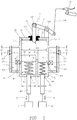
- a preferred embodiment of the hydraulic brake device with a time difference in the present invention includes at least a driving device 1, a housing 2, a first pump mechanism 3 and a second pump mechanism 4 as main components combined together.
- Said driving device 1 is connected to the brake operating element A1 of the vehicle, the driving device 1 is provided with a pushing block 10, and the pushing block 10 is located in the cavity room 20 of the housing 2, a coupling groove 100 is provided at an upper center position of said pushing block 10, and a driving rod 12 is mounted on the coupling groove 100.
- Said driving device 1 is provided with a lever 11 above said housing 2, a fulcrum 110 is arranged on the lever 11, one end of said lever 11 is connected with the cable wire A10 of the brake operating assembly A1, and the other end is coupled with said driving rod 12, an active fulcrum 120 is arranged between the lever 11 and the driving rod 12.
- the lever 11 can be used to drive the driving rod 12 to generate a downward pushing pressure, and push the pushing block 10 to generate a downward displacement.
- the distance at which the pushing block 10 is displaced is determined by the brake operating element A1, that is, the greater the force output by the brake operating element A1, the longer the distance move by the pushing block 10 (As shown in Fig. 2 and Fig. 3 ).
- the driving device 1 is provided with a rod holder 13 and a through hole 130 is formed on the rod holder 13.
- Said driving rod 12 is mounted in the through hole 130 of the rod holder 13
- the rod holder 13 can be made of a flexible material such as rubber or silicone, so that an optimum sealing effect can be achieved between the driving rod 12 and the casing 2.
- Said housing 2 is provided with a cavity room 20, a rod hole 22 is formed on the upper wall surface 21 of the housing 2, and said rod holder 13 is mounted in the rod hole 22.
- said first pump mechanism 3 is mounted in the casing 2, the first pump mechanism 3 is provided with a first piston 30 and a first chamber 31 below the push block 10, and the first piston 30 is arranged in the first chamber 31.
- An interval space is formed between the first chamber 31 and the push block 10, the upper end of said first piston 30 is extended out of the first chamber 31, and the upper end of said first piston 30 is pressed against the lower end of the push block 10.
- Said first chamber 31 is internally filled with hydraulic fluid, and the first piston 30 is provided with a sealing member, such as an oil seal or an O-ring (not shown in Figures).
- a first elastic member 32 such as a compression spring, is disposed in the first chamber 31, and the first elastic member 32 is located between the lower end of the first piston 30 and the lower wall surface 310 of the first chamber 31.
- the lower wall surface 310 of said first chamber 31 is formed a first hole 311, and the first hole 311 is provided with a first output duct 313, so that the first output pipe 313 can output the hydraulic fluid inside the first chamber 31 to the rear wheel brake 50, and to drive the rear wheel brake 50 to generate a braking force.
- said first chamber 31 is provided with a first replenishing device 33
- the first replenishing device 33 can be disposed on the outer side of the casing 2
- the first replenishing device 33 can be made of plastic or other light-transmissive material, so that the user can observe the amount of hydraulic fluid of the first replenishing device 33.
- Said first replenishing device 33 is provided with a first regulating valve 330, and a first connecting duct 314 is formed between the first chamber 31 and the first replenishing device 33, said first regulating valve 330 can adjust or supplement the hydraulic fluid in the first chamber 31.
- the first replenishing device 33 is provided with a first fluid storage tank 331.
- the first fluid storage tank 331 is provided with a first plug 332, and the hydraulic fluid in the first fluid storage tank 331 can be replenished or replaced through the first plug 332.
- a gas temporary storage space S1 is disposed in the first fluid storage tank 331, and said first connection duct 314 is formed at a highest water level of the hydraulic fluid of the first chamber 31. In this way, the air bubbles generated from the first chamber 31 can be transported to the gas temporary storage space S1 of the first fluid storage tank 330 through the first output duct 313 and the first regulating valve 330 to maintain the quality and temperature of the hydraulic fluid in the first chamber 31.
- said second pump mechanism 4 is mounted in the casing 2, the second pump mechanism 4 is provided with a second piston 40 and a second chamber 41 below the push block 10, and the second piston 40 is arranged in the second chamber 41.
- An interval space is formed between the second chamber 41 and the push block 10, the upper end of said second piston 40 is extended out of the second chamber 41, and the upper end of the second piston 40 and the lower end of the push block 10 have a separation distance d1.
- Said second chamber 41 is internally filled with hydraulic fluid, and the second piston 40 is provided with a sealing member, such as an oil seal or an O-ring (not shown in Figures).
- a second elastic member 42 such as a compression spring, is disposed in the second chamber 41, and the second elastic member 42 is located between the lower end of the second piston 40 and the lower wall surface 410 of the second chamber 41.
- the lower wall surface 410 of said second chamber 41 is formed a second hole 411, and the second hole 411 is provided with a second output duct 413, so that the second output pipe 413 can output the hydraulic fluid inside the second chamber 41 to the front wheel brake 51, and to drive the front wheel brake 51 to generate a braking force.
- said second chamber 41 is provided with a second replenishing device 43
- the second replenishing device 43 can be disposed on the outer side of the casing 2
- the second replenishing device 43 can be made of plastic or other light-transmissive material, so that the user can observe the amount of hydraulic fluid of the second replenishing device 43.
- Said second replenishing device 43 is provided with a second regulating valve 430, and a second connecting duct 414 is formed between the second chamber 41 and the second replenishing device 43, said second regulating valve 430 can adjust or supplement the hydraulic fluid in the second chamber 41.
- the second replenishing device 43 is provided with a second fluid storage tank 431.
- the second fluid storage tank 431 is provided with a second plug 432, and the hydraulic fluid in the second fluid storage tank 431 can be replenished or replaced through the second plug 432.
- a gas temporary storage space S2 is disposed in the second fluid storage tank 431, and said second connection duct 414 is formed at a highest water level of the hydraulic fluid of the second chamber 41. In this way, the air bubbles generated from the second chamber 41 can be transported to the gas temporary storage space S2 of the second fluid storage tank 430 through the second output duct 413 and the second regulating valve 430 to maintain the quality and temperature of the hydraulic fluid in the second chamber 41.
- the first piston 30 of the first pump mechanism 3 and the second piston 40 of the second pump mechanism 4 may be provided in different sizes to provide different braking forces. As shown in Figs. 1 to 3 , since the time for starting the front wheel brake 51 is later than the time for starting the rear wheel brake 50, in order to make the braking force of the front wheel brake 51 larger than the braking force of the rear wheel brake 50, the size D2 of said second piston 40 must be larger than the size D1 of the first piston 30, so that, when the pushing block 10 is pressed to the second piston 40, the second piston 40 can output more hydraulic fluid than the first piston 30, and the hydraulic brake force P2 of the second pump mechanism 4 can be greater than the hydraulic brake force P1 of the first pump mechanism 3
- said first replenishing device 33 of the first pump mechanism 3 and said second replenishing device 43 of the second pump mechanism 4 may be the same replenishing device, and the hydraulic fluid of the first chamber 31 of the first pump mechanism 3 and the hydraulic fluid of the second chamber 41 of the second pump mechanism 4 are simultaneously supplied by only one replenishing device.
- said first pump mechanism 3 may not be provided with the first replenishing device 33, and said second pump mechanism 4 may not be provided with the second replenishing device 43, as long as sufficient hydraulic fluid is stored in the first chamber 31 and the second chamber 41, the same effect can be obtained.
- the driving device 1 When the driver activates the brake operating element A1, the driving device 1 will drive the pushing block 10 to press the first piston 30 to move downward. At this time, the first elastic member 32 is compressed, and the first chamber 31 outputs the hydraulic brake force P1 downward to make the rear wheel brake 50 generate the braking force. As shown in Figs. 2 , after the pushing block 10 moves a separation distance d1, the second piston 40 will be synchronously pressed to move downward together. At this time, the second elastic member 42 is compressed, and the second chamber 41 outputs the hydraulic brake force P2 downward to make the front wheel brake 51 generates the braking force.
- a time difference between rear wheel brake 50 and front wheel brake 51 can be achieved by performing one braking action, and through the special size design of the first piston 30 and the second piston 40, the second piston 40 started later can instantaneously output a hydraulic brake force greater than the first piston 30, to let the front wheel braked later have a larger braking force than the rear wheel.
- the present invention can provide at least one set of time difference hydraulic brake device on the vehicle according to requirements.
- the present invention can be provided with two sets of time difference hydraulic brake devices B1, B2, which are respectively connected with two brake operating elements A1, A2.
- the first output ducts 313 of the first pump mechanisms 3 of the two time difference hydraulic brake devices B1, B2 are connected together by a connection valve 315, the hydraulic fluid in each of the first chamber 31 can be output to the rear wheel brake 50 at the same time or separately;
- the second output ducts 413 of the second pump mechanisms 4 of the two time difference hydraulic brake devices B1, B2 are connected together by a connection valve 415, the hydraulic fluid in each of the second chamber 41 can be output to the front wheel brake 51 at the same time or separately.
- the present invention utilizes an innovative brake structure to realize the time difference braking technique in which the rear wheel preferentially activates the braking action, to prevent the vehicles from slipping or spillover.
- this invention has tangible benefits and tallies with progressiveness and novelty demanded by patent laws.
Landscapes
- Engineering & Computer Science (AREA)
- Mechanical Engineering (AREA)
- Transportation (AREA)
- Physics & Mathematics (AREA)
- Fluid Mechanics (AREA)
- Regulating Braking Force (AREA)
- Hydraulic Control Valves For Brake Systems (AREA)
- Braking Systems And Boosters (AREA)
- Transmission Of Braking Force In Braking Systems (AREA)
- Braking Arrangements (AREA)
Applications Claiming Priority (1)
| Application Number | Priority Date | Filing Date | Title |
|---|---|---|---|
| PCT/CN2016/080936 WO2017190280A1 (fr) | 2016-05-04 | 2016-05-04 | Dispositif de freinage à différence de temps de type hydraulique et ensemble associé |
Publications (3)
| Publication Number | Publication Date |
|---|---|
| EP3453602A1 true EP3453602A1 (fr) | 2019-03-13 |
| EP3453602A4 EP3453602A4 (fr) | 2020-04-22 |
| EP3453602B1 EP3453602B1 (fr) | 2022-10-19 |
Family
ID=60202642
Family Applications (1)
| Application Number | Title | Priority Date | Filing Date |
|---|---|---|---|
| EP16900802.6A Active EP3453602B1 (fr) | 2016-05-04 | 2016-05-04 | Dispositif de freinage à différence de temps de type hydraulique et ensemble associé |
Country Status (9)
| Country | Link |
|---|---|
| US (1) | US10814850B2 (fr) |
| EP (1) | EP3453602B1 (fr) |
| JP (1) | JP6626222B2 (fr) |
| KR (1) | KR102133107B1 (fr) |
| AU (1) | AU2016405416B2 (fr) |
| CA (1) | CA3023021C (fr) |
| NZ (1) | NZ747295A (fr) |
| RU (1) | RU2705893C1 (fr) |
| WO (1) | WO2017190280A1 (fr) |
Cited By (1)
| Publication number | Priority date | Publication date | Assignee | Title |
|---|---|---|---|---|
| WO2024180265A1 (fr) * | 2023-02-28 | 2024-09-06 | Xiu Rdi, S.L. | Système de frein combiné pour motocyclettes |
Families Citing this family (6)
| Publication number | Priority date | Publication date | Assignee | Title |
|---|---|---|---|---|
| RU2710313C1 (ru) * | 2016-08-03 | 2019-12-25 | Гинда Нью-Тек Ко., Лтд. | Тормозное устройство гидравлического типа с разновременностью срабатывания |
| KR102233150B1 (ko) * | 2020-08-19 | 2021-03-29 | (주)한국원자력 엔지니어링 | 이륜차의 유압식 제동장치 |
| IT202100011621A1 (it) * | 2021-05-06 | 2022-11-06 | Brembo Spa | Impianto frenante di tipo brake-by-wire per motocicli |
| KR102479622B1 (ko) * | 2022-06-21 | 2022-12-23 | 이규용 | 순차 제동장치 |
| JP7601920B2 (ja) * | 2023-01-30 | 2024-12-17 | 本田技研工業株式会社 | 鞍乗型車両 |
| IT202300007437A1 (it) * | 2023-04-17 | 2024-10-17 | Safim S R L | Dispositivo di frenatura per veicoli |
Family Cites Families (62)
| Publication number | Priority date | Publication date | Assignee | Title |
|---|---|---|---|---|
| US3153328A (en) * | 1959-10-23 | 1964-10-20 | Raymond J Seethaler | Braking system for vehicles |
| FR1369404A (fr) * | 1963-05-25 | 1964-08-14 | Ferodo Sa | Frein à disque ou analogue |
| FR1489777A (fr) * | 1966-06-09 | 1967-07-28 | Ferodo Sa | Installation de freins hydrauliques notamment pour véhicules automobiles |
| DE1655334C3 (de) * | 1966-12-28 | 1974-10-17 | Alfred Teves Gmbh, 6000 Frankfurt | Mechanisch zu betätigende Teilbelagscheibenbremse als Feststellbremse |
| US3554334A (en) * | 1968-06-17 | 1971-01-12 | Keizo Shimano | Hydraulic bicycle brake system |
| GB1326367A (en) * | 1969-09-16 | 1973-08-08 | Girling Ltd | Master cylinder assemblies for hydraulic braking systems of vehicles |
| AU445435B2 (en) * | 1971-07-01 | 1974-02-06 | Improvements in hydraulic braking systems for vehicles | |
| US4326379A (en) * | 1979-11-06 | 1982-04-27 | Societe Anonyme Francaise Du Ferodo | Hydraulic control device for a motor vehicle braking circuit |
| DE3045814A1 (de) * | 1980-12-05 | 1982-07-08 | Alfred Teves Gmbh, 6000 Frankfurt | Zweikreis-hauptbremszylinder |
| US4443040A (en) * | 1981-04-23 | 1984-04-17 | Lucas Industries | Hydraulic boosters for vehicle braking systems |
| JPS5833560A (ja) * | 1981-08-24 | 1983-02-26 | Honda Motor Co Ltd | 車両の制動装置 |
| JPS5849590A (ja) * | 1981-09-19 | 1983-03-23 | 本田技研工業株式会社 | 自動二輪車の制動装置 |
| DE3240542C3 (de) * | 1982-11-03 | 1996-07-04 | Teves Gmbh Alfred | Tandemhauptzylinder |
| DE3321729A1 (de) * | 1983-06-16 | 1984-12-20 | Alfred Teves Gmbh, 6000 Frankfurt | Zweikreishauptzylinder |
| US4559781A (en) * | 1983-10-31 | 1985-12-24 | Allied Corporation | Master cylinder |
| DE3444829A1 (de) * | 1984-12-08 | 1986-06-12 | Robert Bosch Gmbh, 7000 Stuttgart | Bremskraftverstaerker |
| FR2577627B1 (fr) * | 1985-02-20 | 1988-10-14 | Bendix France | Dispositif de commande pour maitre cylindre double |
| DE3715209A1 (de) * | 1986-09-17 | 1988-04-07 | Lucas Ind Plc | Hauptbremszylinder fuer eine hydraulische dreikreis-bremsanlage |
| NO902057L (no) * | 1990-05-09 | 1991-11-11 | Kongsberg Automotive As | Kraftforsterkningsinnretning til inn- og utkobling av kjoeretoeyclutcher. |
| RU2032564C1 (ru) * | 1992-09-15 | 1995-04-10 | Салават Гумарович Султанов | Гидравлическая тормозная система автотранспортного средства |
| DE19534111A1 (de) * | 1995-09-14 | 1997-03-20 | Manfred Joos | Vorderradbremsanlage für Motorräder |
| JPH10236375A (ja) * | 1997-03-03 | 1998-09-08 | Honda Motor Co Ltd | 自動2輪車用制動装置 |
| US6082831A (en) * | 1998-04-22 | 2000-07-04 | General Motors Corporation | Electro-hydraulic brake apply system displacement augmentation |
| US6390566B1 (en) * | 1999-05-25 | 2002-05-21 | Nissin Kogyo Co., Ltd. | Vehicle braking system |
| US6209687B1 (en) * | 1999-07-02 | 2001-04-03 | Travis S. Hundley | Dual brake handle |
| DE19932670C2 (de) * | 1999-07-13 | 2002-11-07 | Lucas Ind Plc | Hauptzylinderanordnung |
| DE10034787A1 (de) * | 2000-07-18 | 2002-01-31 | Deere & Co | Zweistufiges Ventil |
| US6564553B2 (en) * | 2000-11-09 | 2003-05-20 | Bosch Braking Systems Co., Ltd. | Braking pressure intensifying master cylinder |
| CN1205084C (zh) * | 2000-11-10 | 2005-06-08 | 阮志成 | 油压同步平衡刹车装置 |
| US6606859B1 (en) * | 2002-02-01 | 2003-08-19 | Robert Bosch Corporation | Master cylinder |
| JP3992997B2 (ja) * | 2002-02-28 | 2007-10-17 | 株式会社日立製作所 | マスタシリンダ |
| GB2389157A (en) * | 2002-06-01 | 2003-12-03 | New Holland Belgium | Preventing toppling forward of an agricultural vehicle with a raised weight elevating the centre of gravity by limiting brake force |
| AU2002337622A1 (en) * | 2002-09-05 | 2004-03-29 | Freni Brembo S.P.A. | Vehicle braking system master cylinder |
| CN1206127C (zh) * | 2003-07-10 | 2005-06-15 | 周国兴 | 摩托车安全刹车系统 |
| CN2863626Y (zh) * | 2005-01-20 | 2007-01-31 | 屠炳录 | 双主缸同步制动装置 |
| DE102005037792B3 (de) * | 2005-08-10 | 2007-05-31 | Lucas Automotive Gmbh | Hauptbremszylinderanordnung für eine hydraulische Kraftfahrzeugbremsanlage und Kraftfahrzeugbremsanlage |
| EP1795420B1 (fr) * | 2005-12-08 | 2010-09-08 | Nissin Kogyo Co., Ltd. | Système de freinage verrouillé pour véhicule avec guidon |
| JP2007176340A (ja) | 2005-12-28 | 2007-07-12 | Nissin Kogyo Co Ltd | バーハンドル車両用連動ブレーキ機構 |
| DE102006021817B4 (de) * | 2006-05-10 | 2008-07-31 | Lucas Automotive Gmbh | Hauptbremszylinderanordnung für eine hydraulische Kraftfahrzeugsbremsanlage und Kraftfahrzeugbremsanlage |
| CA2586533A1 (fr) * | 2007-04-27 | 2008-10-27 | Eric Siegrist | Cylindre a maitre frein a deux phases |
| CN100503354C (zh) * | 2007-07-17 | 2009-06-24 | 捷安特(中国)有限公司 | 改善油压碟刹前后轮刹车作动时差的自行车 |
| JP4890378B2 (ja) * | 2007-07-31 | 2012-03-07 | 日立オートモティブシステムズ株式会社 | ブレーキ装置 |
| JP4934547B2 (ja) * | 2007-08-27 | 2012-05-16 | 本田技研工業株式会社 | 車両用クラッチ油圧システム |
| CN102256845A (zh) * | 2008-12-18 | 2011-11-23 | 罗伯特·博世有限公司 | 制动力放大器 |
| CN201472594U (zh) * | 2009-06-22 | 2010-05-19 | 徐盟贵 | 二轮车的前后刹车连动装置 |
| TWI433793B (zh) * | 2011-07-20 | 2014-04-11 | Univ Dayeh | Adjustable brake mechanism |
| TW201313541A (zh) * | 2011-09-23 | 2013-04-01 | Well Child Technology Co | 安全煞車裝置 |
| DE102011083873B4 (de) * | 2011-09-30 | 2026-02-12 | Robert Bosch Gmbh | Hauptbremszylinder für ein Bremssystem eines Fahrzeugs und Herstellungsverfahren für einen Hauptbremszylinder |
| WO2014073051A1 (fr) * | 2012-11-07 | 2014-05-15 | トヨタ自動車株式会社 | Maître-cylindre et dispositif de maître-cylindre |
| JP5733291B2 (ja) * | 2012-11-08 | 2015-06-10 | トヨタ自動車株式会社 | マスタシリンダ装置 |
| JP5831427B2 (ja) * | 2012-11-08 | 2015-12-09 | トヨタ自動車株式会社 | マスタシリンダ装置 |
| JP5692202B2 (ja) * | 2012-11-08 | 2015-04-01 | トヨタ自動車株式会社 | マスタシリンダおよびマスタシリンダ装置 |
| TWI478843B (zh) * | 2013-01-25 | 2015-04-01 | Jui Lung Chang | 齒輪式時差煞車裝置 |
| JP2014144739A (ja) * | 2013-01-30 | 2014-08-14 | Honda Motor Co Ltd | ブレーキキャリパ |
| DE102013216423A1 (de) * | 2013-03-05 | 2014-09-11 | Continental Teves Ag & Co. Ohg | Druckbereitstellungseinrichtung und Bremsanlage |
| DE102014205431A1 (de) * | 2013-03-28 | 2014-10-02 | Robert Bosch Gmbh | Bremssystem für ein Fahrzeug |
| FR3008667B1 (fr) * | 2013-07-19 | 2015-09-04 | Bosch Gmbh Robert | Unite de commande de freinage |
| JP6296349B2 (ja) * | 2014-06-25 | 2018-03-20 | 日立オートモティブシステムズ株式会社 | ブレーキ装置 |
| JP6327420B2 (ja) * | 2015-03-31 | 2018-05-23 | 本田技研工業株式会社 | クラッチ制御装置 |
| DE102015208876A1 (de) * | 2015-05-13 | 2016-11-17 | Robert Bosch Gmbh | Hydraulikaggregat und Bremssystem für ein Fahrzeug |
| CN106608252A (zh) * | 2015-10-26 | 2017-05-03 | 张瑞龙 | 油压式时差煞车装置 |
| RU2710313C1 (ru) * | 2016-08-03 | 2019-12-25 | Гинда Нью-Тек Ко., Лтд. | Тормозное устройство гидравлического типа с разновременностью срабатывания |
-
2016
- 2016-05-04 CA CA3023021A patent/CA3023021C/fr active Active
- 2016-05-04 US US16/094,459 patent/US10814850B2/en active Active
- 2016-05-04 EP EP16900802.6A patent/EP3453602B1/fr active Active
- 2016-05-04 NZ NZ747295A patent/NZ747295A/en not_active IP Right Cessation
- 2016-05-04 KR KR1020187030783A patent/KR102133107B1/ko not_active Expired - Fee Related
- 2016-05-04 JP JP2018557015A patent/JP6626222B2/ja not_active Expired - Fee Related
- 2016-05-04 WO PCT/CN2016/080936 patent/WO2017190280A1/fr not_active Ceased
- 2016-05-04 AU AU2016405416A patent/AU2016405416B2/en not_active Ceased
- 2016-05-04 RU RU2018141834A patent/RU2705893C1/ru active
Cited By (1)
| Publication number | Priority date | Publication date | Assignee | Title |
|---|---|---|---|---|
| WO2024180265A1 (fr) * | 2023-02-28 | 2024-09-06 | Xiu Rdi, S.L. | Système de frein combiné pour motocyclettes |
Also Published As
| Publication number | Publication date |
|---|---|
| EP3453602A4 (fr) | 2020-04-22 |
| AU2016405416A1 (en) | 2018-11-08 |
| CA3023021C (fr) | 2020-12-29 |
| EP3453602B1 (fr) | 2022-10-19 |
| JP2019518644A (ja) | 2019-07-04 |
| WO2017190280A1 (fr) | 2017-11-09 |
| JP6626222B2 (ja) | 2019-12-25 |
| NZ747295A (en) | 2020-01-31 |
| US10814850B2 (en) | 2020-10-27 |
| CA3023021A1 (fr) | 2017-11-09 |
| KR102133107B1 (ko) | 2020-07-20 |
| KR20180132087A (ko) | 2018-12-11 |
| US20190118787A1 (en) | 2019-04-25 |
| RU2705893C1 (ru) | 2019-11-12 |
| AU2016405416B2 (en) | 2020-05-14 |
Similar Documents
| Publication | Publication Date | Title |
|---|---|---|
| AU2016405416B2 (en) | Hydraulic-type time-difference brake apparatus and assembly thereof | |
| EP3495254B1 (fr) | Dispositif de freinage hydraulique reposant sur une différence de temps | |
| CN107645998A (zh) | 用于车辆的组合制动装置 | |
| JP6300894B2 (ja) | 油圧式時間差ブレーキ装置 | |
| CN205524219U (zh) | 变助力比真空助力器、制动系统和车辆 | |
| CN103171730B (zh) | 操纵手柄车辆用制动控制装置 | |
| CN107161131B (zh) | 一种机动车及其刹车系统 | |
| TWI607906B (zh) | 油壓式時差煞車裝置(一) | |
| CN107344590B (zh) | 油压式时差刹车装置及其总成 | |
| EP2896554B1 (fr) | Dispositif auxiliaire pour ensemble de frein hydraulique | |
| CN104249728A (zh) | 电子液压刹车装置 | |
| JP3121856U (ja) | 操作力補助装置 | |
| HK1240551A (en) | Hydraulic brake device with time lag function | |
| HK1240551A1 (en) | Hydraulic brake device with time lag function | |
| CN107685825B (zh) | 油压式时差煞车装置 | |
| JP6200867B2 (ja) | 車両用ブレーキシステムの入力装置 | |
| HK1240551B (zh) | 油压式时差刹车装置及其总成 | |
| JP6386870B2 (ja) | 車両用ブレーキシステムの入力装置 | |
| HK1245203A1 (zh) | 油压式时差刹车装置 | |
| JP2010052496A (ja) | タンデム式マスタシリンダ |
Legal Events
| Date | Code | Title | Description |
|---|---|---|---|
| STAA | Information on the status of an ep patent application or granted ep patent |
Free format text: STATUS: THE INTERNATIONAL PUBLICATION HAS BEEN MADE |
|
| PUAI | Public reference made under article 153(3) epc to a published international application that has entered the european phase |
Free format text: ORIGINAL CODE: 0009012 |
|
| STAA | Information on the status of an ep patent application or granted ep patent |
Free format text: STATUS: REQUEST FOR EXAMINATION WAS MADE |
|
| 17P | Request for examination filed |
Effective date: 20181023 |
|
| AK | Designated contracting states |
Kind code of ref document: A1 Designated state(s): AL AT BE BG CH CY CZ DE DK EE ES FI FR GB GR HR HU IE IS IT LI LT LU LV MC MK MT NL NO PL PT RO RS SE SI SK SM TR |
|
| AX | Request for extension of the european patent |
Extension state: BA ME |
|
| DAV | Request for validation of the european patent (deleted) | ||
| DAX | Request for extension of the european patent (deleted) | ||
| A4 | Supplementary search report drawn up and despatched |
Effective date: 20200323 |
|
| RIC1 | Information provided on ipc code assigned before grant |
Ipc: B62L 5/18 20060101ALI20200317BHEP Ipc: B62L 3/08 20060101AFI20200317BHEP Ipc: B62L 3/02 20060101ALI20200317BHEP Ipc: B62L 5/20 20060101ALI20200317BHEP Ipc: B60T 8/26 20060101ALI20200317BHEP |
|
| GRAP | Despatch of communication of intention to grant a patent |
Free format text: ORIGINAL CODE: EPIDOSNIGR1 |
|
| STAA | Information on the status of an ep patent application or granted ep patent |
Free format text: STATUS: GRANT OF PATENT IS INTENDED |
|
| INTG | Intention to grant announced |
Effective date: 20220509 |
|
| GRAS | Grant fee paid |
Free format text: ORIGINAL CODE: EPIDOSNIGR3 |
|
| GRAA | (expected) grant |
Free format text: ORIGINAL CODE: 0009210 |
|
| STAA | Information on the status of an ep patent application or granted ep patent |
Free format text: STATUS: THE PATENT HAS BEEN GRANTED |
|
| AK | Designated contracting states |
Kind code of ref document: B1 Designated state(s): AL AT BE BG CH CY CZ DE DK EE ES FI FR GB GR HR HU IE IS IT LI LT LU LV MC MK MT NL NO PL PT RO RS SE SI SK SM TR |
|
| REG | Reference to a national code |
Ref country code: GB Ref legal event code: FG4D |
|
| REG | Reference to a national code |
Ref country code: CH Ref legal event code: EP |
|
| REG | Reference to a national code |
Ref country code: IE Ref legal event code: FG4D |
|
| REG | Reference to a national code |
Ref country code: DE Ref legal event code: R096 Ref document number: 602016075820 Country of ref document: DE |
|
| REG | Reference to a national code |
Ref country code: AT Ref legal event code: REF Ref document number: 1525398 Country of ref document: AT Kind code of ref document: T Effective date: 20221115 |
|
| REG | Reference to a national code |
Ref country code: LT Ref legal event code: MG9D |
|
| REG | Reference to a national code |
Ref country code: NL Ref legal event code: MP Effective date: 20221019 |
|
| REG | Reference to a national code |
Ref country code: AT Ref legal event code: MK05 Ref document number: 1525398 Country of ref document: AT Kind code of ref document: T Effective date: 20221019 |
|
| PG25 | Lapsed in a contracting state [announced via postgrant information from national office to epo] |
Ref country code: NL Free format text: LAPSE BECAUSE OF FAILURE TO SUBMIT A TRANSLATION OF THE DESCRIPTION OR TO PAY THE FEE WITHIN THE PRESCRIBED TIME-LIMIT Effective date: 20221019 |
|
| PG25 | Lapsed in a contracting state [announced via postgrant information from national office to epo] |
Ref country code: SE Free format text: LAPSE BECAUSE OF FAILURE TO SUBMIT A TRANSLATION OF THE DESCRIPTION OR TO PAY THE FEE WITHIN THE PRESCRIBED TIME-LIMIT Effective date: 20221019 Ref country code: PT Free format text: LAPSE BECAUSE OF FAILURE TO SUBMIT A TRANSLATION OF THE DESCRIPTION OR TO PAY THE FEE WITHIN THE PRESCRIBED TIME-LIMIT Effective date: 20230220 Ref country code: NO Free format text: LAPSE BECAUSE OF FAILURE TO SUBMIT A TRANSLATION OF THE DESCRIPTION OR TO PAY THE FEE WITHIN THE PRESCRIBED TIME-LIMIT Effective date: 20230119 Ref country code: LT Free format text: LAPSE BECAUSE OF FAILURE TO SUBMIT A TRANSLATION OF THE DESCRIPTION OR TO PAY THE FEE WITHIN THE PRESCRIBED TIME-LIMIT Effective date: 20221019 Ref country code: FI Free format text: LAPSE BECAUSE OF FAILURE TO SUBMIT A TRANSLATION OF THE DESCRIPTION OR TO PAY THE FEE WITHIN THE PRESCRIBED TIME-LIMIT Effective date: 20221019 Ref country code: ES Free format text: LAPSE BECAUSE OF FAILURE TO SUBMIT A TRANSLATION OF THE DESCRIPTION OR TO PAY THE FEE WITHIN THE PRESCRIBED TIME-LIMIT Effective date: 20221019 Ref country code: AT Free format text: LAPSE BECAUSE OF FAILURE TO SUBMIT A TRANSLATION OF THE DESCRIPTION OR TO PAY THE FEE WITHIN THE PRESCRIBED TIME-LIMIT Effective date: 20221019 |
|
| PG25 | Lapsed in a contracting state [announced via postgrant information from national office to epo] |
Ref country code: RS Free format text: LAPSE BECAUSE OF FAILURE TO SUBMIT A TRANSLATION OF THE DESCRIPTION OR TO PAY THE FEE WITHIN THE PRESCRIBED TIME-LIMIT Effective date: 20221019 Ref country code: PL Free format text: LAPSE BECAUSE OF FAILURE TO SUBMIT A TRANSLATION OF THE DESCRIPTION OR TO PAY THE FEE WITHIN THE PRESCRIBED TIME-LIMIT Effective date: 20221019 Ref country code: LV Free format text: LAPSE BECAUSE OF FAILURE TO SUBMIT A TRANSLATION OF THE DESCRIPTION OR TO PAY THE FEE WITHIN THE PRESCRIBED TIME-LIMIT Effective date: 20221019 Ref country code: IS Free format text: LAPSE BECAUSE OF FAILURE TO SUBMIT A TRANSLATION OF THE DESCRIPTION OR TO PAY THE FEE WITHIN THE PRESCRIBED TIME-LIMIT Effective date: 20230219 Ref country code: HR Free format text: LAPSE BECAUSE OF FAILURE TO SUBMIT A TRANSLATION OF THE DESCRIPTION OR TO PAY THE FEE WITHIN THE PRESCRIBED TIME-LIMIT Effective date: 20221019 Ref country code: GR Free format text: LAPSE BECAUSE OF FAILURE TO SUBMIT A TRANSLATION OF THE DESCRIPTION OR TO PAY THE FEE WITHIN THE PRESCRIBED TIME-LIMIT Effective date: 20230120 |
|
| REG | Reference to a national code |
Ref country code: DE Ref legal event code: R097 Ref document number: 602016075820 Country of ref document: DE |
|
| PG25 | Lapsed in a contracting state [announced via postgrant information from national office to epo] |
Ref country code: SM Free format text: LAPSE BECAUSE OF FAILURE TO SUBMIT A TRANSLATION OF THE DESCRIPTION OR TO PAY THE FEE WITHIN THE PRESCRIBED TIME-LIMIT Effective date: 20221019 Ref country code: RO Free format text: LAPSE BECAUSE OF FAILURE TO SUBMIT A TRANSLATION OF THE DESCRIPTION OR TO PAY THE FEE WITHIN THE PRESCRIBED TIME-LIMIT Effective date: 20221019 Ref country code: EE Free format text: LAPSE BECAUSE OF FAILURE TO SUBMIT A TRANSLATION OF THE DESCRIPTION OR TO PAY THE FEE WITHIN THE PRESCRIBED TIME-LIMIT Effective date: 20221019 Ref country code: DK Free format text: LAPSE BECAUSE OF FAILURE TO SUBMIT A TRANSLATION OF THE DESCRIPTION OR TO PAY THE FEE WITHIN THE PRESCRIBED TIME-LIMIT Effective date: 20221019 Ref country code: CZ Free format text: LAPSE BECAUSE OF FAILURE TO SUBMIT A TRANSLATION OF THE DESCRIPTION OR TO PAY THE FEE WITHIN THE PRESCRIBED TIME-LIMIT Effective date: 20221019 |
|
| PGFP | Annual fee paid to national office [announced via postgrant information from national office to epo] |
Ref country code: IT Payment date: 20230531 Year of fee payment: 8 Ref country code: FR Payment date: 20230517 Year of fee payment: 8 Ref country code: DE Payment date: 20230505 Year of fee payment: 8 |
|
| PLBE | No opposition filed within time limit |
Free format text: ORIGINAL CODE: 0009261 |
|
| STAA | Information on the status of an ep patent application or granted ep patent |
Free format text: STATUS: NO OPPOSITION FILED WITHIN TIME LIMIT |
|
| PG25 | Lapsed in a contracting state [announced via postgrant information from national office to epo] |
Ref country code: SK Free format text: LAPSE BECAUSE OF FAILURE TO SUBMIT A TRANSLATION OF THE DESCRIPTION OR TO PAY THE FEE WITHIN THE PRESCRIBED TIME-LIMIT Effective date: 20221019 Ref country code: AL Free format text: LAPSE BECAUSE OF FAILURE TO SUBMIT A TRANSLATION OF THE DESCRIPTION OR TO PAY THE FEE WITHIN THE PRESCRIBED TIME-LIMIT Effective date: 20221019 |
|
| 26N | No opposition filed |
Effective date: 20230720 |
|
| PGFP | Annual fee paid to national office [announced via postgrant information from national office to epo] |
Ref country code: GB Payment date: 20230522 Year of fee payment: 8 |
|
| PG25 | Lapsed in a contracting state [announced via postgrant information from national office to epo] |
Ref country code: SI Free format text: LAPSE BECAUSE OF FAILURE TO SUBMIT A TRANSLATION OF THE DESCRIPTION OR TO PAY THE FEE WITHIN THE PRESCRIBED TIME-LIMIT Effective date: 20221019 |
|
| REG | Reference to a national code |
Ref country code: CH Ref legal event code: PL |
|
| PG25 | Lapsed in a contracting state [announced via postgrant information from national office to epo] |
Ref country code: MC Free format text: LAPSE BECAUSE OF FAILURE TO SUBMIT A TRANSLATION OF THE DESCRIPTION OR TO PAY THE FEE WITHIN THE PRESCRIBED TIME-LIMIT Effective date: 20221019 |
|
| REG | Reference to a national code |
Ref country code: BE Ref legal event code: MM Effective date: 20230531 |
|
| PG25 | Lapsed in a contracting state [announced via postgrant information from national office to epo] |
Ref country code: MC Free format text: LAPSE BECAUSE OF FAILURE TO SUBMIT A TRANSLATION OF THE DESCRIPTION OR TO PAY THE FEE WITHIN THE PRESCRIBED TIME-LIMIT Effective date: 20221019 Ref country code: LU Free format text: LAPSE BECAUSE OF NON-PAYMENT OF DUE FEES Effective date: 20230504 Ref country code: LI Free format text: LAPSE BECAUSE OF NON-PAYMENT OF DUE FEES Effective date: 20230531 Ref country code: CH Free format text: LAPSE BECAUSE OF NON-PAYMENT OF DUE FEES Effective date: 20230531 |
|
| REG | Reference to a national code |
Ref country code: IE Ref legal event code: MM4A |
|
| PG25 | Lapsed in a contracting state [announced via postgrant information from national office to epo] |
Ref country code: IE Free format text: LAPSE BECAUSE OF NON-PAYMENT OF DUE FEES Effective date: 20230504 |
|
| PG25 | Lapsed in a contracting state [announced via postgrant information from national office to epo] |
Ref country code: IE Free format text: LAPSE BECAUSE OF NON-PAYMENT OF DUE FEES Effective date: 20230504 |
|
| PG25 | Lapsed in a contracting state [announced via postgrant information from national office to epo] |
Ref country code: BE Free format text: LAPSE BECAUSE OF NON-PAYMENT OF DUE FEES Effective date: 20230531 |
|
| PG25 | Lapsed in a contracting state [announced via postgrant information from national office to epo] |
Ref country code: BG Free format text: LAPSE BECAUSE OF FAILURE TO SUBMIT A TRANSLATION OF THE DESCRIPTION OR TO PAY THE FEE WITHIN THE PRESCRIBED TIME-LIMIT Effective date: 20221019 |
|
| PG25 | Lapsed in a contracting state [announced via postgrant information from national office to epo] |
Ref country code: BG Free format text: LAPSE BECAUSE OF FAILURE TO SUBMIT A TRANSLATION OF THE DESCRIPTION OR TO PAY THE FEE WITHIN THE PRESCRIBED TIME-LIMIT Effective date: 20221019 |
|
| REG | Reference to a national code |
Ref country code: DE Ref legal event code: R119 Ref document number: 602016075820 Country of ref document: DE |
|
| GBPC | Gb: european patent ceased through non-payment of renewal fee |
Effective date: 20240504 |
|
| PG25 | Lapsed in a contracting state [announced via postgrant information from national office to epo] |
Ref country code: DE Free format text: LAPSE BECAUSE OF NON-PAYMENT OF DUE FEES Effective date: 20241203 |
|
| PG25 | Lapsed in a contracting state [announced via postgrant information from national office to epo] |
Ref country code: FR Free format text: LAPSE BECAUSE OF NON-PAYMENT OF DUE FEES Effective date: 20240531 |
|
| PG25 | Lapsed in a contracting state [announced via postgrant information from national office to epo] |
Ref country code: IT Free format text: LAPSE BECAUSE OF NON-PAYMENT OF DUE FEES Effective date: 20240504 Ref country code: GB Free format text: LAPSE BECAUSE OF NON-PAYMENT OF DUE FEES Effective date: 20240504 |
|
| PG25 | Lapsed in a contracting state [announced via postgrant information from national office to epo] |
Ref country code: CY Free format text: LAPSE BECAUSE OF FAILURE TO SUBMIT A TRANSLATION OF THE DESCRIPTION OR TO PAY THE FEE WITHIN THE PRESCRIBED TIME-LIMIT; INVALID AB INITIO Effective date: 20160504 |
|
| PG25 | Lapsed in a contracting state [announced via postgrant information from national office to epo] |
Ref country code: HU Free format text: LAPSE BECAUSE OF FAILURE TO SUBMIT A TRANSLATION OF THE DESCRIPTION OR TO PAY THE FEE WITHIN THE PRESCRIBED TIME-LIMIT; INVALID AB INITIO Effective date: 20160504 |
|
| PG25 | Lapsed in a contracting state [announced via postgrant information from national office to epo] |
Ref country code: TR Free format text: LAPSE BECAUSE OF FAILURE TO SUBMIT A TRANSLATION OF THE DESCRIPTION OR TO PAY THE FEE WITHIN THE PRESCRIBED TIME-LIMIT Effective date: 20221019 |