EP3453632B1 - Contenant en matière plastique et moule de soufflage pour sa fabrication - Google Patents
Contenant en matière plastique et moule de soufflage pour sa fabrication Download PDFInfo
- Publication number
- EP3453632B1 EP3453632B1 EP18199424.5A EP18199424A EP3453632B1 EP 3453632 B1 EP3453632 B1 EP 3453632B1 EP 18199424 A EP18199424 A EP 18199424A EP 3453632 B1 EP3453632 B1 EP 3453632B1
- Authority
- EP
- European Patent Office
- Prior art keywords
- stand
- container
- plastics material
- beverage container
- sections
- Prior art date
- Legal status (The legal status is an assumption and is not a legal conclusion. Google has not performed a legal analysis and makes no representation as to the accuracy of the status listed.)
- Active
Links
Images




Classifications
-
- B—PERFORMING OPERATIONS; TRANSPORTING
- B65—CONVEYING; PACKING; STORING; HANDLING THIN OR FILAMENTARY MATERIAL
- B65D—CONTAINERS FOR STORAGE OR TRANSPORT OF ARTICLES OR MATERIALS, e.g. BAGS, BARRELS, BOTTLES, BOXES, CANS, CARTONS, CRATES, DRUMS, JARS, TANKS, HOPPERS, FORWARDING CONTAINERS; ACCESSORIES, CLOSURES, OR FITTINGS THEREFOR; PACKAGING ELEMENTS; PACKAGES
- B65D1/00—Rigid or semi-rigid containers having bodies formed in one piece, e.g. by casting metallic material, by moulding plastics, by blowing vitreous material, by throwing ceramic material, by moulding pulped fibrous material or by deep-drawing operations performed on sheet material
- B65D1/02—Bottles or similar containers with necks or like restricted apertures, designed for pouring contents
- B65D1/0223—Bottles or similar containers with necks or like restricted apertures, designed for pouring contents characterised by shape
- B65D1/0261—Bottom construction
- B65D1/0284—Bottom construction having a discontinuous contact surface, e.g. discrete feet
-
- B—PERFORMING OPERATIONS; TRANSPORTING
- B29—WORKING OF PLASTICS; WORKING OF SUBSTANCES IN A PLASTIC STATE IN GENERAL
- B29C—SHAPING OR JOINING OF PLASTICS; SHAPING OF MATERIAL IN A PLASTIC STATE, NOT OTHERWISE PROVIDED FOR; AFTER-TREATMENT OF THE SHAPED PRODUCTS, e.g. REPAIRING
- B29C49/00—Blow-moulding, i.e. blowing a preform or parison to a desired shape within a mould; Apparatus therefor
- B29C49/42—Component parts, details or accessories; Auxiliary operations
- B29C49/48—Moulds
-
- B—PERFORMING OPERATIONS; TRANSPORTING
- B29—WORKING OF PLASTICS; WORKING OF SUBSTANCES IN A PLASTIC STATE IN GENERAL
- B29C—SHAPING OR JOINING OF PLASTICS; SHAPING OF MATERIAL IN A PLASTIC STATE, NOT OTHERWISE PROVIDED FOR; AFTER-TREATMENT OF THE SHAPED PRODUCTS, e.g. REPAIRING
- B29C49/00—Blow-moulding, i.e. blowing a preform or parison to a desired shape within a mould; Apparatus therefor
- B29C49/42—Component parts, details or accessories; Auxiliary operations
- B29C49/48—Moulds
- B29C2049/4879—Moulds characterised by mould configurations
- B29C2049/4882—Mould cavity geometry
-
- B—PERFORMING OPERATIONS; TRANSPORTING
- B29—WORKING OF PLASTICS; WORKING OF SUBSTANCES IN A PLASTIC STATE IN GENERAL
- B29L—INDEXING SCHEME ASSOCIATED WITH SUBCLASS B29C, RELATING TO PARTICULAR ARTICLES
- B29L2031/00—Other particular articles
- B29L2031/712—Containers; Packaging elements or accessories, Packages
- B29L2031/7158—Bottles
Definitions
- the present invention relates to a plastic container and in particular to a plastic container for holding liquids and especially beverages.
- plastic containers have long been known from the prior art. Recently, these containers are increasingly based on the task of reducing the cost of materials and at the same time, however, maintaining the stability of the container.
- This relates, for example, to stability in relation to internal pressures caused by the filling product, but also in relation to external stresses that can occur, for example, when the containers are stacked.
- the bottom of these containers is particularly critical in the design of such containers, since it also serves as a standing surface on the one hand and is also particularly exposed to the pressures caused by the liquid on the other.
- Different floor designs are known from the prior art.
- the invention is particularly directed to a container which is suitable for hot filling of beverages, for example for filling with iced teas.
- Such containers suitable for hot filling generally have several feet, in particular a six-foot base design with different diameters and base heights.
- customers usually want a low floor design, similar to that of a so-called still water floor.
- the implementation is very difficult or has disadvantages, such as an increased weight of the plastic preforms from which the containers are made,
- the present invention is therefore based on the object of developing a container or, in particular, a container base which allows a reduced base height even for higher loads, in particular due to pressures in the interior of the container.
- this bottom design should preferably be suitable for filling processes with hot or warm contents under internal pressure.
- feet are usually also provided, but these form a more punctiform base for the container.
- this circumferential angle very large, i. at least in such a way that along a circle the actual standing area takes up more than half of this circle.
- An angular width of the standing surface is preferably obtained from the opening angle of the incision or the groove and the number of incisions or grooves used.
- This The base is therefore preferably an interrupted full circle. In total, the segments of the stand area take up more than 50% of the full circle.
- a ring segment-shaped i.e. in particular a standing surface in the form of a partially interrupted ring.
- These respective interruptions originate from the grooves mentioned.
- the grooves are kept very narrow and thus the standing surface or the standing section is relatively slightly interrupted compared to containers known from the prior art.
- a sum of these circumferential angles is advantageously greater than 200 °, preferably greater than 220 °, preferably greater than 240 °, preferably greater than 270 ° and preferably greater than 300 °. This means that by far predominantly the feet form a standing surface with respect to a full circle.
- the individual stand sections are advantageously of the same size and are arranged one after the other in the circumferential direction. As mentioned above, these stand sections are each interrupted by the grooves.
- all of the grooves are essentially identical in terms of their geometric structure. In other words, only one type of grooves is preferably provided. However, it would also be conceivable that, in addition to the said first grooves, second grooves can also be arranged, which, for example, alternate with the above-mentioned first grooves.
- the container is advantageously a hot-fill container, ie a container which is intended and intended to be filled with a heated medium.
- the container design described here is preferably suitable for hot-filled products with an internal pressure of up to 4.0 bar, for pressureless hot and cold-filled products and also for cold-filled products with an internal pressure of up to 6.0 bar.
- the container is advantageously a PET container with a capacity of 100 ml to 5.0 l.
- a cross section of the mouth is smaller than a cross section of the base body.
- the base body preferably has a circular cross section.
- the base section also has a circular cross section.
- the groove base has a curved or at least partially curved profile in a projection in a radial direction of the container. A radius of curvature of this groove round is advantageously more than 5 mm, preferably more than 10 mm, preferably more than 20 mm. It would also be possible for the said groove base to run in a straight line, at least in sections.
- the groove base has a width in a circumferential direction which is between 0.1 mm and 10 mm, preferably between 1 mm and 8 mm and particularly preferably between 1 mm and 6 mm.
- the maximum width of this groove base is preferably one third of an outer diameter of the container.
- the groove base has a constant width.
- the groove base it would also be conceivable for the groove base to widen outwards, with the edges of this groove base preferably running in a straight line.
- a ratio between the width of the groove base and a distance between two standing sections delimiting this groove is between 1: 1 and 1:10, preferably between 1: 1.1 and 1: 8, preferably between 1: 1.5 and 1: 6.
- the container has an external thread.
- said groove base extends in a straight line at least in sections in a circumferential direction of the container.
- the containers known from the prior art usually have curved courses of these groove bottoms.
- the base contour on the inside or the contour in the region of the groove base is described, starting from a center of the base, by several successive sections with at least partially different curvatures.
- the first section can be a straight line starting from the center point of the bottom section.
- a first curved section with a predetermined (curvature) radius can connect to this straight line.
- the groove or the groove base does not extend into the center of the container bottom, that is to say as far as the injection point.
- This first curved section can be followed by a second curved section with a further (curvature) radius, and this second curved section can be followed by a third curved section with a third (final) (curvature) radius.
- This geometry can form the guide contour for the inner cross-sectional contour and preferably indicate the course of the incision or the groove.
- the mentioned (constant) (curvature) radii or curved sections, which adjoin the straight section, can also be replaced by a common spline of the nth degree.
- one of the curved sections could also be shown as a straight line.
- the variant with a spline it merges with a constant curvature, at least with a tangent constant, into a straight line that is parallel to the outer diameter.
- transitions of the radii or of the curved sections are advantageously at least partially and preferably all tangent-continuous.
- the transitions of the splines are preferably curvature-continuous, but at least tangent-continuous.
- this contour is that the pressure forces acting on the bottom center are diverted through these "cuts" in the side wall of the bottle. It is therefore advantageous that the starting point of the guide contour in the center of the container is lower than the end point of the guide contour.
- At least one groove starting from the groove base, has an opening angle that is smaller than 45 °, preferably smaller than 30 °, preferably smaller than 25 ° and particularly preferably smaller than 20 °.
- very narrow grooves are proposed. As mentioned above, these narrow grooves can increase the footprint of the container and at the same time enable a relatively flat bottom design. This angle is preferably formed between the bottom of the groove on the one hand and the ends of the two standing sections or feet that are adjacent to this groove and reach the groove.
- the ring segment-shaped standing sections span a standing plane of the container which is perpendicular to the longitudinal direction of the container.
- the standing surface itself is preferably ring-shaped or ring-segment-shaped, but a plane spanned by this extends perpendicular to the longitudinal axis of the container.
- at least one wall section extends at least in sections with respect to the standing plane at an angle that is greater than 45 °, preferably greater than 60 °, preferably greater than 75 °.
- the container has wall sections running very steeply in a standing state.
- the container has between three and twelve feet, preferably between four and eight feet and particularly preferably between four and seven feet.
- incision segments could be defined, an incision segment being composed of a continuous incision or the groove and part of the outer surface of the container.
- the bottom can advantageously contain a number of a minimum of 3 incision segments up to a maximum of 12 incision segments on the circumference.
- the outer dimensions of the floor are advantageously determined by the outer diameter and the floor height.
- the size of a standing circle diameter can be determined by a ratio to the outer diameter of the container. A relationship is advantageous between an outer diameter of the plastic container and a standing circle diameter between 0.5 and 0.99, preferably between 0.5 and 0.9 and particularly preferably between 0.6 and 0.8.
- At least one wall section or wall partial section of a groove extends at least in sections in a straight line in at least one predetermined direction.
- this wall section extends in a straight line in a direction which also has at least one component in the longitudinal direction of the container.
- such a wall section can be defined between a certain point of the groove, which is at a certain radial distance from the longitudinal direction, to a certain point of the base, which has the same radial distance from the longitudinal direction of the container.
- these wall sections are usually designed to be curved.
- the straight design makes it possible to increase the stability of the floor.
- An essentially straight course is understood to mean that the radius of curvature of this wall section is greater than 4 cm, preferably greater than 8 cm, preferably greater than 10 cm and preferably greater than 20 cm.
- this wall section extends, at least in sections, in a straight line in two predetermined mutually perpendicular directions. This wall section thus advantageously forms a flat surface.
- the base section advantageously has, at least in sections, a first dome-like structure extending in the direction of a center of the base section. This dome-like structure is directed towards an inner volume of the container. This means that in the case of an upright container, a center of the bottom section is spaced from a standing surface. In addition, however, it would also be possible for the container to have a second dome-like structure in which there is an injection point for the container.
- the center of the bottom section is arranged lower in the longitudinal direction of the plastic container than a predetermined further area of the bottom section and in particular than an area in which this bottom section merges into the base body.
- the bottom section has an injection point in its center and at least one groove base extends up to this injection point or is less than 5 mm away from this injection point.
- the grooves are preferably brought very close to the injection point or an area surrounding the injection point.
- at least one groove also extends in a circumferential section of the bottom section.
- a circumferential section is to be understood here in particular as that area which is visible from the side when the container is placed on a standing surface, or generally that section which is visible in a radial direction perpendicular to the longitudinal direction.
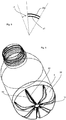
- Fig. 1 shows a side view of a container 1 according to the invention.
- This container has a mouth section 12, to which a base body 14 adjoins in a longitudinal direction L of the container 1.
- This base body 14 forms the essential receiving volume for receiving a liquid.
- a base section 2 adjoins this base body 14.
- the reference character R denotes a radial direction of the container.
- the container 1 preferably has a thread 22 and a support ring 24 located below this thread.
- the bottom section 2 has a plurality of grooves 6 here.
- Fig. 1 One already acknowledges Fig. 1 that these grooves are cut much deeper than grooves known from the prior art.
- These grooves 6 each have a wall section 64 which extends from a groove base (not shown) to the feet 4.
- the reference numeral 4a relates on an outer wall of these feet 4, which at the same time form stand sections 20a, 20b and 20c.
- the other booth sections are in Fig. 1 not visible.
- the reference character H denotes a height of the floor, which is designed to be variable here. It can be seen, however, that the floor height H is relatively low compared to the floor heights known from the prior art (in particular of containers that can be filled with hot water).
- Fig. 2 shows a detailed representation of a bottom section 2.
- the groove 6 and the groove base 62 can be seen here.
- the groove 6 is designed symmetrically with respect to this groove base 62.
- the reference character b denotes an opening angle of the groove 6, which, as mentioned above, is defined between the groove base and the ends of the standing sections 20a and 20b which reach up to the groove 6.
- the reference numeral 32 denotes a peripheral area of the base section 2, it being evident that the grooves 6 also extend into this peripheral area 32.
- Fig. 3 shows a detailed representation of a groove 6.
- the groove base 62 and the wall section 64 adjoining the groove base can be seen.
- This wall section 64 here forms a flat surface, as mentioned above.
- the reference symbol D1 shows a distance between the two stand sections 20a and 20b and the reference symbol D2 shows the width of the groove base 62.
- a ratio between these two lengths is preferably less than 10: 1, preferably less than 8: 1 and particularly preferred less than 5: 1.
- Fig. 3a shows a cross-sectional view of the container in the area of a groove and viewed in the radial direction of the container.
- the cross-sectional contour of the incision or the groove is described by two parallel straight lines, namely the groove base 62 on the one hand and the geometric distance 65 between two standing sections on the one hand and two straight lines symmetrical to the center line M, which are formed by the wall sections 64 on the other.
- the straight lines formed by the wall sections 64 can also be replaced by two symmetrical radii or splines.
- the wall sections do not extend in a straight line but in a curved manner.
- the straight lines or the wall sections 64 are controlled via a ratio that results from the length of the groove base 62 and the distance 65.
- the distance 65 (D2) is at least the same, but preferably greater than that in FIG Fig. 3a shown length D2 of the groove base.
- the length of the section 64 is preferably also greater than the length D2.
- the ratio of the length of the straight line or of the section is preferably between 8 times and 12 times, preferably between 9 and 11 times and particularly preferably approximately 10 times the distance D2.
- Figure 3b shows a further detailed representation of a groove 6. It can be seen here that the groove in the Fig. 2 shown points P1, P2 is flattened or trimmed.
- the reference symbol T denotes a tangent which is applied to this flattened or trimmed area.
- An angle d between this tangent T and the center line M is between 0 ° and 89 °, preferably between 10 ° and 80 °, preferably between 20 ° and 70 ° and particularly preferably between 30 ° and 60 °.
- the area in these points P1 and P2 can again be curved.
- Fig. 4 shows a view from below of the bottom section 2. In the center of the bottom section there is an injection point 18 here.
- the individual stand sections 20a, 20b, 20c, 20d, 20e, 20f and 20g are also shown here. These each enclose angles a1, a2 ..., in the circumferential direction. The individual circumferential angles are each the same size. The grooves are located between these stand sections, so that they do not form any stand areas.
- Fig. 5 shows an illustration of the stand areas.
- the standing section 20a in turn forms a standing surface which has a circumferential angle a1.
- the circumferential angle c1 relates to the angle formed by the groove, that is, no standing surface of the container is formed in this section.
- These angles are here in a ratio which is between 1: 1 and 10: 1, preferably between 1.5: 1 and 1: 8 and particularly preferred is between 1: 2 and 1: 6.
- This ratio is in turn also decisive for the proportion of the stand sections in a full circle, since, as mentioned above, the individual stands are preferably designed in the same way and also the grooves formed between the stands.
- Fig. 6 shows a perspective view of a container according to the invention.
- FIG. 14 shows a view along the line AA Fig. 2 .
- the reference symbol H2 denotes a difference in height between this standing surface 63 and a height level of the injection point. This height, which is also a measure of the ground clearance, can be chosen variably and is between 3mm and 15mm and preferably between 4mm and 10mm.
- the groove base 62 is only very slightly curved and, in other words, has very high radii of curvature.
- radii of curvature R1 / Fig. 3a
- R1 / Fig. 3a there are relatively small radii of curvature (R1 / Fig. 3a ), which are preferably between a radius of 0.001 mm and a radius of 15 mm, preferably between a radius of 0.1 mm and a radius of 10 mm, preferably between a radius of 0.2 mm and a radius of 5 mm. It would be possible that it is a constant radius of curvature. However, it would also be conceivable that this radius of curvature changes.
- the radius of curvature could thus decrease or increase from radially inside to radially outside. It would also be conceivable that the radius of curvature is initially increased and then decreased again or, conversely, initially decreased and then increased again. For example, the radius of curvature could change between 0.1 mm and 10 mm, such a change preferably taking place continuously.
- the reference symbol K1 relates to a radius of curvature of the groove base 62.
- Fig. 8 shows an outer surface of the container 1 or the base contour on the outside.
- essentially horizontal is understood to mean that an angle of inclination of this straight line relative to an exactly horizontal direction is by no more than 10 °, preferably by no more than 7 °, preferably by by no more than 5 °, particularly preferably by no more than 3 ° and particularly preferably by no more than 1 °.
- slight curvatures would also come into consideration here, for example curvatures with a radius of curvature of more than 10 cm, preferably of more than 20 cm.
- a second section 44 adjoins this horizontal straight line 42 or the first horizontal section 42.
- An angle of this second section 44 is between 0 ° - 45 ° with respect to the axis of rotation Z (10, Fig.1 ).
- This second section 44 is followed by a curved section or a spline 45.
- a curve of the radius of curvature of this curved section can be described by a polynomial of the nth degree (where n is preferably between 3 and 8).
- This curved section 45 also forms the dome-like structure of the container bottom 2.
- the reference symbol DA denotes an outer diameter of the container 1 or its bottom section and the reference symbol DS denotes a base "circle" diameter, ie the diameter or radius that would be taken up by a base area expanded to a full circle.
- the stand section 20 adjoins this curved section 45.
- This standing section 20 also extends here in the radial direction of the floor, preferably horizontally, so that an annular standing surface results.
- a curved section or spline 46 adjoins this stand section 20, and this is followed by a further curved section 48.
- the so-called outer surface of the floor geometry is generated from this contour by a rotation about the axis of rotation Z. This axis of rotation also determines the longitudinal direction of the container.
- transitions of the radii or of the straight sections are preferably at least partially and particularly preferably all tangent-continuous.
- the transitions of the curved sections 45, 46, 48 splines are preferably curvature-continuous, but particularly preferably at least tangent-continuous.
- the curved sections 45, 46, 48 can also be at least partially replaced by the geometry of a straight line or a (constant) radius.
- the curvature of the spline 45, 46, 48 can, as mentioned above, through a polynomial of the nth degree can be described.
- Fig. 9 shows a representation of the course of curvature in a region of a groove base or the base contour on the inside.
- a straight section 52 is initially provided, which preferably also runs in a substantially horizontal direction, whereby “substantially horizontal” is understood to mean that an angle of inclination with respect to this straight line an exactly horizontal direction deviates in amount by no more than 10 °, preferably by no more than 7 °, preferably by no more than 5 °, particularly preferably by no more than 3 ° and particularly preferably by no more than 1 °.
- a first curved section 54 and a second curved section 56 adjoin this rectilinear section. These two curved sections 54 and 56 together form the groove base 62. A further curved section 58 adjoins the curved section 56.
- Fig. 10 shows another perspective illustration of the container bottom 2 to illustrate the geometries.
- the entire incision or groove segment 70 is shown here, which is composed of a continuous groove 6 or the continuous incision 6 and part of the outer surface 74.
- the reference symbol 75 here denotes the angular width of the standing surface and the reference symbol 76 the opening angle of the groove 6.
Landscapes
- Engineering & Computer Science (AREA)
- Mechanical Engineering (AREA)
- Manufacturing & Machinery (AREA)
- Ceramic Engineering (AREA)
- Containers Having Bodies Formed In One Piece (AREA)
Claims (11)
- Récipient en matière plastique pour boisson avec une embouchure (12), par l'intermédiaire de laquelle un liquide peut être prélevé du récipient, avec un corps de base (14) se raccordant dans une direction longitudinale (L) à ladite embouchure (12) et une section de fond (2) se raccordant dans ladite direction longitudinale (L) audit corps de base (14), dans lequel la section de fond (2) présente au moins trois pieds d'appui (4), dans lequel des surfaces extérieures (4a) desdits pieds d'appui (4) réalisent respectivement une section d'appui (20a, 20b, 20c), s'étendant par endroits en forme de segment annulaire sur un angle périphérique (a1, a2, a3..) spécifié, du récipient en matière plastique pour boisson (1) et dans lequel au moins trois rainures (6) sont réalisées entre lesdits pieds d'appui, dans lequel lesdites rainures (6) s'étendent au moins également dans une direction (R) radiale perpendiculaire à la direction longitudinale (L) du récipient en matière plastique pour boisson, dans lequel lesdites rainures (6) présentent respectivement une base de rainure (62) s'étendant au moins également dans la direction radiale ainsi qu'une section de paroi (64), qui s'étend depuis ladite base de rainure (62) au moins également vers une section d'appui (20a, 20b, 20c) d'un pied d'appui adjacent à ladite base de rainure (62),
dans lequel une somme desdits angles périphériques (a1, a2, a3..) est supérieure à 180°, dans lequel les sections d'appui (20a, 20b, 20c) en forme de segment annulaire déploient un plan d'appui du récipient, qui est perpendiculaire à la direction longitudinale (L) du récipient, et dans lequel en outre la section de fond (1) présente en son centre un point d'injection (18),
caractérisé en ce que
au moins une base de rainure atteint ledit point d'injection (18) ou est espacée dudit point d'injection à une distance inférieure à 5 mm et en outre en ce qu'une différence de hauteur (H2) entre une surface d'appui (63) et un niveau de hauteur du point d'injection (18) est comprise entre 3 mm et 15 mm et cette hauteur, qui est aussi une mesure pour la garde au sol, peut être choisie de manière variable. - Récipient en matière plastique pour boisson (1) selon la revendication 1,
caractérisé en ce que
au moins une rainure (6) présente, en partant de sa base de rainure (62), un angle d'ouverture (b), qui est inférieur à 45°, de manière préférée inférieur à 30°, de manière préférée inférieur à 25°, de manière préférée inférieur à 20°. - Récipient en matière plastique pour boisson (1) selon au moins l'une des revendications précédentes,
caractérisé en ce que
au moins une section partielle de paroi (64) s'étend au moins par endroits par rapport au plan d'appui selon un angle (a), qui est supérieur à 45°, de manière préférée supérieur à 60°, de manière préférée supérieur à 75°. - Récipient en matière plastique pour boisson (1) selon au moins l'une des revendications précédentes,
caractérisé en ce que
le récipient présente entre 3 et 12 pieds d'appui, de manière préférée entre 4 et 8 pieds d'appui et de manière particulièrement préférée entre 4 et 7 pieds d'appui. - Récipient en matière plastique pour boisson (1) selon au moins l'une des revendications précédentes,
caractérisé en ce que
un rapport entre un diamètre extérieur du récipient en matière plastique (1) et un diamètre circulaire d'appui se situe entre 0,5 et 0,99, de manière préférée entre 0,5 et 0,9 et de manière particulièrement préférée entre 0,6 et 0,8. - Récipient en matière plastique pour boisson (1) selon au moins l'une des revendications précédentes,
caractérisé en ce que
au moins une section de paroi (64) s'étend au moins par endroits de manière rectiligne dans au moins une direction spécifiée. - Récipient en matière plastique pour boisson (1) selon la revendication 6,
caractérisé en ce que
ladite section de paroi (64) s'étend au moins par endroits de manière rectiligne dans deux directions spécifiées perpendiculaires l'une à l'autre. - Récipient en matière plastique pour boisson (1) selon au moins l'une quelconque des revendications précédentes,
caractérisé en ce que
la section de fond présente au moins par endroits une première structure en forme de dôme s'étendant en direction d'un centre de la section de fond (2). - Récipient en matière plastique pour boisson (1) selon la revendication 1,
caractérisé en ce que
le centre (18) de la section de fond (2) est disposé de manière plus basse dans la direction longitudinale du récipient en matière plastique qu'une autre section (58) de la section de fond. - Récipient en matière plastique pour boisson (1) selon au moins l'une quelconque des revendications précédentes,
caractérisé en ce que
au moins une rainure s'étend également dans une section périphérique (32) de la section de fond. - Moule de soufflage, dans lequel le moule de soufflage réalise un espace creux, à l'intérieur duquel une préforme en matière plastique peut être expansée du fait de l'action exercée par un milieu coulant contre une paroi intérieure du moule de soufflage,
caractérisé en ce que
le moule de soufflage présente un élément de fond, qui est adapté pour produire une section de fond (2) du récipient, dans lequel la section de fond (2) présente au moins trois pieds d'appui (4), dans lequel des surfaces extérieures (4a) desdits pieds d'appui (4) réalisent respectivement une section d'appui (20a, 20b, 20c) s'étendant par endroits en forme de segment annulaire sur un angle périphérique (a1, a2, a3..) spécifié du récipient en matière plastique pour boisson (1) et dans lequel au moins trois rainures (6) sont réalisées entre lesdits pieds d'appui, dans lequel lesdites rainures (6) s'étendent au moins également dans une direction (R) radiale perpendiculaire à la direction longitudinale (L) du récipient en matière plastique pour boisson, dans lequel lesdites rainures (6) présentent respectivement une base de rainure (62) s'étendant au moins également dans la direction radiale ainsi qu'une section de paroi (64), qui s'étend depuis ladite base de rainure (62) au moins également en direction d'une section d'appui (20a, 20b, 20c) d'un pied d'appui adjacent par rapport à la base de rainure (62) et dans lequel une somme desdits angles périphérique (a1, a2, a3..) est supérieure à 180°, caractérisé en ce qu'il est mis au point et prévu pour fabriquer un récipient en plastique de boisson selon au moins l'une quelconque des revendications précédentes.
Applications Claiming Priority (3)
| Application Number | Priority Date | Filing Date | Title |
|---|---|---|---|
| DE201310103777 DE102013103777A1 (de) | 2013-04-15 | 2013-04-15 | Kunststoffbehältnis |
| EP14714669.0A EP2986517B1 (fr) | 2013-04-15 | 2014-03-28 | Récipient de boisson en matière synthétique et moule de soufflage pour sa fabrication |
| PCT/EP2014/056276 WO2014170115A1 (fr) | 2013-04-15 | 2014-03-28 | Récipient en matière synthétique et moule de soufflage pour sa fabrication |
Related Parent Applications (1)
| Application Number | Title | Priority Date | Filing Date |
|---|---|---|---|
| EP14714669.0A Division EP2986517B1 (fr) | 2013-04-15 | 2014-03-28 | Récipient de boisson en matière synthétique et moule de soufflage pour sa fabrication |
Publications (2)
| Publication Number | Publication Date |
|---|---|
| EP3453632A1 EP3453632A1 (fr) | 2019-03-13 |
| EP3453632B1 true EP3453632B1 (fr) | 2020-09-09 |
Family
ID=50424232
Family Applications (2)
| Application Number | Title | Priority Date | Filing Date |
|---|---|---|---|
| EP18199424.5A Active EP3453632B1 (fr) | 2013-04-15 | 2014-03-28 | Contenant en matière plastique et moule de soufflage pour sa fabrication |
| EP14714669.0A Active EP2986517B1 (fr) | 2013-04-15 | 2014-03-28 | Récipient de boisson en matière synthétique et moule de soufflage pour sa fabrication |
Family Applications After (1)
| Application Number | Title | Priority Date | Filing Date |
|---|---|---|---|
| EP14714669.0A Active EP2986517B1 (fr) | 2013-04-15 | 2014-03-28 | Récipient de boisson en matière synthétique et moule de soufflage pour sa fabrication |
Country Status (5)
| Country | Link |
|---|---|
| US (2) | USD739245S1 (fr) |
| EP (2) | EP3453632B1 (fr) |
| CN (1) | CN204998900U (fr) |
| DE (1) | DE102013103777A1 (fr) |
| WO (1) | WO2014170115A1 (fr) |
Families Citing this family (26)
| Publication number | Priority date | Publication date | Assignee | Title |
|---|---|---|---|---|
| US10604296B2 (en) | 2010-04-19 | 2020-03-31 | Merrilee Kick | Container |
| PE20141925A1 (es) * | 2011-08-31 | 2014-12-05 | Amcor Ltd | Base de recipiente de peso ligero |
| CH707262A2 (de) * | 2012-11-30 | 2014-05-30 | Alpla Werke | Kunststoffbehälter. |
| FR3013335B1 (fr) * | 2013-11-15 | 2016-01-15 | Sidel Participations | Recipient en matiere thermoplastique a fond de type petaloide a soufflabilite augmentee |
| USD781712S1 (en) * | 2014-03-24 | 2017-03-21 | B. Braun Melsungen Ag | Bottle |
| USD760589S1 (en) * | 2015-04-03 | 2016-07-05 | Tsi Manufacturing, Llc | Bottle |
| US9677988B1 (en) | 2015-07-10 | 2017-06-13 | David E. Doggett | Integrating radiation collection and detection apparatus |
| US9366617B1 (en) * | 2015-07-10 | 2016-06-14 | David E. Doggett | Self-stirring container |
| USD807189S1 (en) * | 2015-09-18 | 2018-01-09 | Niagara Bottling, Llc | Bottle |
| USD818368S1 (en) * | 2015-10-23 | 2018-05-22 | Niagara Bottling, Llc | Plastic utility bottle with narrow neck |
| USD805393S1 (en) * | 2015-11-05 | 2017-12-19 | Pretium Packaging, L.L.C. | Container |
| FR3057246B1 (fr) * | 2016-10-06 | 2022-12-16 | Sidel Participations | Fond petaloide a vallee brisee |
| USD820683S1 (en) * | 2016-12-01 | 2018-06-19 | Govino, Llc | Bottle |
| EP3676188A1 (fr) * | 2017-08-31 | 2020-07-08 | The Procter and Gamble Company | Articles rigides comprenant un coin bien défini |
| USD860805S1 (en) * | 2018-04-16 | 2019-09-24 | Societe Des Eaux De Volvic | Bottle |
| MX2020011255A (es) * | 2018-04-26 | 2020-11-12 | Graham Packaging Co | Recipiente de relleno presurizado resistente al agrietamiento del anillo de pie. |
| USD856809S1 (en) * | 2018-05-23 | 2019-08-20 | Bibita Group Shpk | Beverage bottle |
| US10926911B2 (en) | 2018-10-15 | 2021-02-23 | Pepsico. Inc. | Plastic bottle with base |
| JP7454914B2 (ja) | 2019-03-29 | 2024-03-25 | サントリーホールディングス株式会社 | プラスチックボトル |
| USD1013512S1 (en) | 2019-10-10 | 2024-02-06 | Merrilee Kick | Container |
| JP7370248B2 (ja) * | 2019-12-27 | 2023-10-27 | 株式会社吉野工業所 | ボトル |
| AU2021202920A1 (en) * | 2020-05-08 | 2021-11-25 | Orora Packaging Australia Pty Ltd | A bottle, and an insert and a mould for making the bottle |
| USD959275S1 (en) * | 2020-11-25 | 2022-08-02 | Hint, Inc. | Bottle |
| USD1000274S1 (en) * | 2021-08-06 | 2023-10-03 | Logoplaste Innovation Lab, Lda. | Bottle base |
| US11975889B2 (en) | 2021-09-02 | 2024-05-07 | Merrilee Kick | Container apparatus |
| USD1085883S1 (en) * | 2023-09-28 | 2025-07-29 | Plastipak Packaging, Inc. | Container base |
Family Cites Families (22)
| Publication number | Priority date | Publication date | Assignee | Title |
|---|---|---|---|---|
| US3598270A (en) * | 1969-04-14 | 1971-08-10 | Continental Can Co | Bottom end structure for plastic containers |
| US5024340A (en) * | 1990-07-23 | 1991-06-18 | Sewell Plastics, Inc. | Wide stance footed bottle |
| US5133468A (en) * | 1991-06-14 | 1992-07-28 | Constar Plastics Inc. | Footed hot-fill container |
| GB9716422D0 (en) * | 1997-08-05 | 1997-10-08 | Constar International Uk Limit | Plastics bottle |
| US20040173565A1 (en) * | 1999-12-01 | 2004-09-09 | Frank Semersky | Pasteurizable wide-mouth container |
| JP4178531B2 (ja) * | 2002-09-30 | 2008-11-12 | 株式会社吉野工業所 | 合成樹脂製壜容器の底部構造 |
| US6971530B2 (en) * | 2003-12-12 | 2005-12-06 | Plastipak Packaging, Inc. | Plastic container having stepped neck finish |
| USD517918S1 (en) * | 2004-05-04 | 2006-03-28 | Compagnie Gervais Danone | Bottle |
| US7381559B2 (en) * | 2004-06-09 | 2008-06-03 | Scientific Plastic Products, Inc. | Fermentation flask for cultivating microorganisms |
| USD547196S1 (en) * | 2005-06-03 | 2007-07-24 | Sidel | Bottle |
| JP4826379B2 (ja) * | 2006-07-31 | 2011-11-30 | 東洋製罐株式会社 | 合成樹脂製容器 |
| FR2904808B1 (fr) * | 2006-08-08 | 2011-03-04 | Sidel Participations | Fond de corps creux obtenu par soufflage ou etirage soufflage d'une preforme en materiau thermoplastique, corps creux conprenant un tel fond |
| USD592066S1 (en) * | 2007-10-12 | 2009-05-12 | Sidel Participations | Bottle |
| USD601901S1 (en) * | 2008-02-15 | 2009-10-13 | Sidel Participations | Bottle |
| USD602367S1 (en) * | 2008-02-15 | 2009-10-20 | Sidel Participations | Bottle |
| JP5024168B2 (ja) * | 2008-03-25 | 2012-09-12 | 東洋製罐株式会社 | 合成樹脂製容器 |
| FR2932458B1 (fr) * | 2008-06-13 | 2010-08-20 | Sidel Participations | Recipient, notamment bouteille, en matiere thermoplastique equipe d'un fond renforce |
| USD607733S1 (en) * | 2008-07-23 | 2010-01-12 | Industries Lassonde Inc. | Plastic bottle |
| USD626851S1 (en) * | 2009-02-27 | 2010-11-09 | Pepsico, Inc. | Bottle |
| USD629304S1 (en) * | 2009-02-27 | 2010-12-21 | Pepsico, Inc. | Bottle |
| DE102010009926A1 (de) * | 2010-02-25 | 2011-08-25 | KHS Corpoplast GmbH, 22145 | Verfahren zur Herstellung von blasgeformten Behältern sowie blasgeformter Behälter |
| FR2959214B1 (fr) * | 2010-04-21 | 2012-06-29 | Sidel Participations | Fond de recipient petaloide renforce |
-
2013
- 2013-04-15 DE DE201310103777 patent/DE102013103777A1/de not_active Withdrawn
- 2013-05-30 US US29/456,356 patent/USD739245S1/en active Active
-
2014
- 2014-03-28 US US14/651,464 patent/US20160167825A1/en not_active Abandoned
- 2014-03-28 CN CN201490000296.0U patent/CN204998900U/zh not_active Expired - Lifetime
- 2014-03-28 EP EP18199424.5A patent/EP3453632B1/fr active Active
- 2014-03-28 WO PCT/EP2014/056276 patent/WO2014170115A1/fr not_active Ceased
- 2014-03-28 EP EP14714669.0A patent/EP2986517B1/fr active Active
Non-Patent Citations (1)
| Title |
|---|
| None * |
Also Published As
| Publication number | Publication date |
|---|---|
| CN204998900U (zh) | 2016-01-27 |
| USD739245S1 (en) | 2015-09-22 |
| US20160167825A1 (en) | 2016-06-16 |
| EP3453632A1 (fr) | 2019-03-13 |
| EP2986517A1 (fr) | 2016-02-24 |
| EP2986517B1 (fr) | 2018-10-10 |
| WO2014170115A1 (fr) | 2014-10-23 |
| DE102013103777A1 (de) | 2014-10-16 |
Similar Documents
| Publication | Publication Date | Title |
|---|---|---|
| EP3453632B1 (fr) | Contenant en matière plastique et moule de soufflage pour sa fabrication | |
| EP2735517B1 (fr) | Récipient en plastique avec un fond base renforcé | |
| EP2764979B1 (fr) | Récipient en matière plastique | |
| AT395573B (de) | Behaelter aus kunststoff mit kreisfoermigem querschnitt | |
| DE3874558T2 (de) | Blasgeformter kunststoffbehaelter. | |
| DE102012003219B4 (de) | Kunststoffbehältnis | |
| EP3458370B1 (fr) | Bouteille en matière plastique munie de bandes de tension en intersection | |
| EP2925615B1 (fr) | Récipient en matière plastique | |
| EP3048059B1 (fr) | Récipient en matière plastique muni de portions de col rectilignes et procédé de remplissage | |
| EP3770073A1 (fr) | Récipient en matière plastique à géométrie à bande de traction dans la zone de fond | |
| EP2036820B1 (fr) | Bouteille en plastique | |
| DE68913263T2 (de) | Behälter. | |
| DE102009044896B3 (de) | Verschlusskappe zum Verschließen eines Behältnisses | |
| DE102012100075A1 (de) | Behältnis mit Gewinde sowie Formwerkzeug zur Herstellung eines solchen | |
| DE102013110139B4 (de) | Kunststoffbehältnis mit wärmestabilem Boden | |
| EP2468645A1 (fr) | Récipient en matériau thermoplastique | |
| DD300086A5 (de) | Vorrichtung und Verfahren in Verbindung mit einem Vorformling mit geodätischen Verstärkungsring | |
| EP3601072B1 (fr) | Contenant en matière plastique à partie fond pivotante | |
| EP4169840A1 (fr) | Récipient en matière plastique pour boissons à stabilité améliorée | |
| DE102019105005A1 (de) | Kunststoffbehältnis mit Rillengeometrie | |
| EP4159629A1 (fr) | Récipient en matière plastique à conception stable de fond | |
| EP3359363A1 (fr) | Préforme pour la fabrication d'un récipient en matériau synthétique dans un procédé d'étirage-soufflage | |
| EP4450410A1 (fr) | Récipient en matière plastique avec pieds aplatis et dispositif de moulage par soufflage | |
| EP4321447A1 (fr) | Récipient en matière plastique avec géométrie de bande de traction au niveau du fond | |
| DE102016118495A1 (de) | Kunststoffbehältnis und Boden für ein Kunststoffbehältnis |
Legal Events
| Date | Code | Title | Description |
|---|---|---|---|
| PUAI | Public reference made under article 153(3) epc to a published international application that has entered the european phase |
Free format text: ORIGINAL CODE: 0009012 |
|
| STAA | Information on the status of an ep patent application or granted ep patent |
Free format text: STATUS: THE APPLICATION HAS BEEN PUBLISHED |
|
| AC | Divisional application: reference to earlier application |
Ref document number: 2986517 Country of ref document: EP Kind code of ref document: P |
|
| AK | Designated contracting states |
Kind code of ref document: A1 Designated state(s): AL AT BE BG CH CY CZ DE DK EE ES FI FR GB GR HR HU IE IS IT LI LT LU LV MC MK MT NL NO PL PT RO RS SE SI SK SM TR |
|
| STAA | Information on the status of an ep patent application or granted ep patent |
Free format text: STATUS: REQUEST FOR EXAMINATION WAS MADE |
|
| 17P | Request for examination filed |
Effective date: 20190912 |
|
| RBV | Designated contracting states (corrected) |
Designated state(s): AL AT BE BG CH CY CZ DE DK EE ES FI FR GB GR HR HU IE IS IT LI LT LU LV MC MK MT NL NO PL PT RO RS SE SI SK SM TR |
|
| GRAP | Despatch of communication of intention to grant a patent |
Free format text: ORIGINAL CODE: EPIDOSNIGR1 |
|
| STAA | Information on the status of an ep patent application or granted ep patent |
Free format text: STATUS: GRANT OF PATENT IS INTENDED |
|
| INTG | Intention to grant announced |
Effective date: 20200318 |
|
| GRAS | Grant fee paid |
Free format text: ORIGINAL CODE: EPIDOSNIGR3 |
|
| GRAA | (expected) grant |
Free format text: ORIGINAL CODE: 0009210 |
|
| STAA | Information on the status of an ep patent application or granted ep patent |
Free format text: STATUS: THE PATENT HAS BEEN GRANTED |
|
| RIN1 | Information on inventor provided before grant (corrected) |
Inventor name: DACHS, ALEXANDER Inventor name: LAPPE, ULRICH Inventor name: KNAPP, PETER Inventor name: WUNDERLICH, STEPHANIE |
|
| AC | Divisional application: reference to earlier application |
Ref document number: 2986517 Country of ref document: EP Kind code of ref document: P |
|
| AK | Designated contracting states |
Kind code of ref document: B1 Designated state(s): AL AT BE BG CH CY CZ DE DK EE ES FI FR GB GR HR HU IE IS IT LI LT LU LV MC MK MT NL NO PL PT RO RS SE SI SK SM TR |
|
| REG | Reference to a national code |
Ref country code: GB Ref legal event code: FG4D Free format text: NOT ENGLISH |
|
| REG | Reference to a national code |
Ref country code: AT Ref legal event code: REF Ref document number: 1311296 Country of ref document: AT Kind code of ref document: T Effective date: 20200915 Ref country code: CH Ref legal event code: EP |
|
| REG | Reference to a national code |
Ref country code: IE Ref legal event code: FG4D Free format text: LANGUAGE OF EP DOCUMENT: GERMAN |
|
| REG | Reference to a national code |
Ref country code: DE Ref legal event code: R096 Ref document number: 502014014749 Country of ref document: DE |
|
| REG | Reference to a national code |
Ref country code: LT Ref legal event code: MG4D |
|
| PG25 | Lapsed in a contracting state [announced via postgrant information from national office to epo] |
Ref country code: GR Free format text: LAPSE BECAUSE OF FAILURE TO SUBMIT A TRANSLATION OF THE DESCRIPTION OR TO PAY THE FEE WITHIN THE PRESCRIBED TIME-LIMIT Effective date: 20201210 Ref country code: FI Free format text: LAPSE BECAUSE OF FAILURE TO SUBMIT A TRANSLATION OF THE DESCRIPTION OR TO PAY THE FEE WITHIN THE PRESCRIBED TIME-LIMIT Effective date: 20200909 Ref country code: LT Free format text: LAPSE BECAUSE OF FAILURE TO SUBMIT A TRANSLATION OF THE DESCRIPTION OR TO PAY THE FEE WITHIN THE PRESCRIBED TIME-LIMIT Effective date: 20200909 Ref country code: SE Free format text: LAPSE BECAUSE OF FAILURE TO SUBMIT A TRANSLATION OF THE DESCRIPTION OR TO PAY THE FEE WITHIN THE PRESCRIBED TIME-LIMIT Effective date: 20200909 Ref country code: HR Free format text: LAPSE BECAUSE OF FAILURE TO SUBMIT A TRANSLATION OF THE DESCRIPTION OR TO PAY THE FEE WITHIN THE PRESCRIBED TIME-LIMIT Effective date: 20200909 Ref country code: NO Free format text: LAPSE BECAUSE OF FAILURE TO SUBMIT A TRANSLATION OF THE DESCRIPTION OR TO PAY THE FEE WITHIN THE PRESCRIBED TIME-LIMIT Effective date: 20201209 Ref country code: BG Free format text: LAPSE BECAUSE OF FAILURE TO SUBMIT A TRANSLATION OF THE DESCRIPTION OR TO PAY THE FEE WITHIN THE PRESCRIBED TIME-LIMIT Effective date: 20201209 |
|
| REG | Reference to a national code |
Ref country code: NL Ref legal event code: MP Effective date: 20200909 |
|
| PG25 | Lapsed in a contracting state [announced via postgrant information from national office to epo] |
Ref country code: PL Free format text: LAPSE BECAUSE OF FAILURE TO SUBMIT A TRANSLATION OF THE DESCRIPTION OR TO PAY THE FEE WITHIN THE PRESCRIBED TIME-LIMIT Effective date: 20200909 Ref country code: RS Free format text: LAPSE BECAUSE OF FAILURE TO SUBMIT A TRANSLATION OF THE DESCRIPTION OR TO PAY THE FEE WITHIN THE PRESCRIBED TIME-LIMIT Effective date: 20200909 Ref country code: LV Free format text: LAPSE BECAUSE OF FAILURE TO SUBMIT A TRANSLATION OF THE DESCRIPTION OR TO PAY THE FEE WITHIN THE PRESCRIBED TIME-LIMIT Effective date: 20200909 |
|
| PG25 | Lapsed in a contracting state [announced via postgrant information from national office to epo] |
Ref country code: EE Free format text: LAPSE BECAUSE OF FAILURE TO SUBMIT A TRANSLATION OF THE DESCRIPTION OR TO PAY THE FEE WITHIN THE PRESCRIBED TIME-LIMIT Effective date: 20200909 Ref country code: PT Free format text: LAPSE BECAUSE OF FAILURE TO SUBMIT A TRANSLATION OF THE DESCRIPTION OR TO PAY THE FEE WITHIN THE PRESCRIBED TIME-LIMIT Effective date: 20210111 Ref country code: RO Free format text: LAPSE BECAUSE OF FAILURE TO SUBMIT A TRANSLATION OF THE DESCRIPTION OR TO PAY THE FEE WITHIN THE PRESCRIBED TIME-LIMIT Effective date: 20200909 Ref country code: CZ Free format text: LAPSE BECAUSE OF FAILURE TO SUBMIT A TRANSLATION OF THE DESCRIPTION OR TO PAY THE FEE WITHIN THE PRESCRIBED TIME-LIMIT Effective date: 20200909 Ref country code: SM Free format text: LAPSE BECAUSE OF FAILURE TO SUBMIT A TRANSLATION OF THE DESCRIPTION OR TO PAY THE FEE WITHIN THE PRESCRIBED TIME-LIMIT Effective date: 20200909 |
|
| PG25 | Lapsed in a contracting state [announced via postgrant information from national office to epo] |
Ref country code: AL Free format text: LAPSE BECAUSE OF FAILURE TO SUBMIT A TRANSLATION OF THE DESCRIPTION OR TO PAY THE FEE WITHIN THE PRESCRIBED TIME-LIMIT Effective date: 20200909 Ref country code: ES Free format text: LAPSE BECAUSE OF FAILURE TO SUBMIT A TRANSLATION OF THE DESCRIPTION OR TO PAY THE FEE WITHIN THE PRESCRIBED TIME-LIMIT Effective date: 20200909 Ref country code: IS Free format text: LAPSE BECAUSE OF FAILURE TO SUBMIT A TRANSLATION OF THE DESCRIPTION OR TO PAY THE FEE WITHIN THE PRESCRIBED TIME-LIMIT Effective date: 20210109 |
|
| REG | Reference to a national code |
Ref country code: DE Ref legal event code: R097 Ref document number: 502014014749 Country of ref document: DE |
|
| PG25 | Lapsed in a contracting state [announced via postgrant information from national office to epo] |
Ref country code: SK Free format text: LAPSE BECAUSE OF FAILURE TO SUBMIT A TRANSLATION OF THE DESCRIPTION OR TO PAY THE FEE WITHIN THE PRESCRIBED TIME-LIMIT Effective date: 20200909 |
|
| PLBE | No opposition filed within time limit |
Free format text: ORIGINAL CODE: 0009261 |
|
| STAA | Information on the status of an ep patent application or granted ep patent |
Free format text: STATUS: NO OPPOSITION FILED WITHIN TIME LIMIT |
|
| 26N | No opposition filed |
Effective date: 20210610 |
|
| PG25 | Lapsed in a contracting state [announced via postgrant information from national office to epo] |
Ref country code: DK Free format text: LAPSE BECAUSE OF FAILURE TO SUBMIT A TRANSLATION OF THE DESCRIPTION OR TO PAY THE FEE WITHIN THE PRESCRIBED TIME-LIMIT Effective date: 20200909 Ref country code: SI Free format text: LAPSE BECAUSE OF FAILURE TO SUBMIT A TRANSLATION OF THE DESCRIPTION OR TO PAY THE FEE WITHIN THE PRESCRIBED TIME-LIMIT Effective date: 20200909 |
|
| PG25 | Lapsed in a contracting state [announced via postgrant information from national office to epo] |
Ref country code: MC Free format text: LAPSE BECAUSE OF FAILURE TO SUBMIT A TRANSLATION OF THE DESCRIPTION OR TO PAY THE FEE WITHIN THE PRESCRIBED TIME-LIMIT Effective date: 20200909 |
|
| REG | Reference to a national code |
Ref country code: CH Ref legal event code: PL |
|
| GBPC | Gb: european patent ceased through non-payment of renewal fee |
Effective date: 20210328 |
|
| REG | Reference to a national code |
Ref country code: BE Ref legal event code: MM Effective date: 20210331 |
|
| PG25 | Lapsed in a contracting state [announced via postgrant information from national office to epo] |
Ref country code: GB Free format text: LAPSE BECAUSE OF NON-PAYMENT OF DUE FEES Effective date: 20210328 Ref country code: LU Free format text: LAPSE BECAUSE OF NON-PAYMENT OF DUE FEES Effective date: 20210328 Ref country code: LI Free format text: LAPSE BECAUSE OF NON-PAYMENT OF DUE FEES Effective date: 20210331 Ref country code: IE Free format text: LAPSE BECAUSE OF NON-PAYMENT OF DUE FEES Effective date: 20210328 Ref country code: CH Free format text: LAPSE BECAUSE OF NON-PAYMENT OF DUE FEES Effective date: 20210331 |
|
| REG | Reference to a national code |
Ref country code: AT Ref legal event code: MM01 Ref document number: 1311296 Country of ref document: AT Kind code of ref document: T Effective date: 20210328 |
|
| PG25 | Lapsed in a contracting state [announced via postgrant information from national office to epo] |
Ref country code: BE Free format text: LAPSE BECAUSE OF NON-PAYMENT OF DUE FEES Effective date: 20210331 |
|
| PG25 | Lapsed in a contracting state [announced via postgrant information from national office to epo] |
Ref country code: AT Free format text: LAPSE BECAUSE OF NON-PAYMENT OF DUE FEES Effective date: 20210328 |
|
| PG25 | Lapsed in a contracting state [announced via postgrant information from national office to epo] |
Ref country code: NL Free format text: LAPSE BECAUSE OF NON-PAYMENT OF DUE FEES Effective date: 20200923 Ref country code: CY Free format text: LAPSE BECAUSE OF FAILURE TO SUBMIT A TRANSLATION OF THE DESCRIPTION OR TO PAY THE FEE WITHIN THE PRESCRIBED TIME-LIMIT Effective date: 20200909 |
|
| PG25 | Lapsed in a contracting state [announced via postgrant information from national office to epo] |
Ref country code: HU Free format text: LAPSE BECAUSE OF FAILURE TO SUBMIT A TRANSLATION OF THE DESCRIPTION OR TO PAY THE FEE WITHIN THE PRESCRIBED TIME-LIMIT; INVALID AB INITIO Effective date: 20140328 |
|
| PG25 | Lapsed in a contracting state [announced via postgrant information from national office to epo] |
Ref country code: MK Free format text: LAPSE BECAUSE OF FAILURE TO SUBMIT A TRANSLATION OF THE DESCRIPTION OR TO PAY THE FEE WITHIN THE PRESCRIBED TIME-LIMIT Effective date: 20200909 |
|
| PG25 | Lapsed in a contracting state [announced via postgrant information from national office to epo] |
Ref country code: TR Free format text: LAPSE BECAUSE OF FAILURE TO SUBMIT A TRANSLATION OF THE DESCRIPTION OR TO PAY THE FEE WITHIN THE PRESCRIBED TIME-LIMIT Effective date: 20200909 |
|
| PG25 | Lapsed in a contracting state [announced via postgrant information from national office to epo] |
Ref country code: MT Free format text: LAPSE BECAUSE OF FAILURE TO SUBMIT A TRANSLATION OF THE DESCRIPTION OR TO PAY THE FEE WITHIN THE PRESCRIBED TIME-LIMIT Effective date: 20200909 |
|
| PGFP | Annual fee paid to national office [announced via postgrant information from national office to epo] |
Ref country code: DE Payment date: 20260204 Year of fee payment: 13 |
|
| PGFP | Annual fee paid to national office [announced via postgrant information from national office to epo] |
Ref country code: IT Payment date: 20260220 Year of fee payment: 13 |
|
| PGFP | Annual fee paid to national office [announced via postgrant information from national office to epo] |
Ref country code: FR Payment date: 20260209 Year of fee payment: 13 |