EP3456470A2 - Système de changement et d'insertion ou de fourniture d'outils à une machine-outil et machine-outil dotée d'un tel système - Google Patents
Système de changement et d'insertion ou de fourniture d'outils à une machine-outil et machine-outil dotée d'un tel système Download PDFInfo
- Publication number
- EP3456470A2 EP3456470A2 EP18194739.1A EP18194739A EP3456470A2 EP 3456470 A2 EP3456470 A2 EP 3456470A2 EP 18194739 A EP18194739 A EP 18194739A EP 3456470 A2 EP3456470 A2 EP 3456470A2
- Authority
- EP
- European Patent Office
- Prior art keywords
- tool
- diameter
- radius
- loaded
- measuring device
- Prior art date
- Legal status (The legal status is an assumption and is not a legal conclusion. Google has not performed a legal analysis and makes no representation as to the accuracy of the status listed.)
- Pending
Links
Images

Classifications
-
- B—PERFORMING OPERATIONS; TRANSPORTING
- B23—MACHINE TOOLS; METAL-WORKING NOT OTHERWISE PROVIDED FOR
- B23Q—DETAILS, COMPONENTS, OR ACCESSORIES FOR MACHINE TOOLS, e.g. ARRANGEMENTS FOR COPYING OR CONTROLLING; MACHINE TOOLS IN GENERAL CHARACTERISED BY THE CONSTRUCTION OF PARTICULAR DETAILS OR COMPONENTS; COMBINATIONS OR ASSOCIATIONS OF METAL-WORKING MACHINES, NOT DIRECTED TO A PARTICULAR RESULT
- B23Q3/00—Devices holding, supporting, or positioning work or tools, of a kind normally removable from the machine
- B23Q3/155—Arrangements for automatic insertion or removal of tools, e.g. combined with manual handling
- B23Q3/157—Arrangements for automatic insertion or removal of tools, e.g. combined with manual handling of rotary tools
- B23Q3/15713—Arrangements for automatic insertion or removal of tools, e.g. combined with manual handling of rotary tools a transfer device taking a single tool from a storage device and inserting it in a spindle
- B23Q3/1572—Arrangements for automatic insertion or removal of tools, e.g. combined with manual handling of rotary tools a transfer device taking a single tool from a storage device and inserting it in a spindle the storage device comprising rotating or circulating storing means
- B23Q3/15753—Arrangements for automatic insertion or removal of tools, e.g. combined with manual handling of rotary tools a transfer device taking a single tool from a storage device and inserting it in a spindle the storage device comprising rotating or circulating storing means the storage means rotating or circulating in a plane perpendicular to the axis of the spindle
-
- B—PERFORMING OPERATIONS; TRANSPORTING
- B23—MACHINE TOOLS; METAL-WORKING NOT OTHERWISE PROVIDED FOR
- B23Q—DETAILS, COMPONENTS, OR ACCESSORIES FOR MACHINE TOOLS, e.g. ARRANGEMENTS FOR COPYING OR CONTROLLING; MACHINE TOOLS IN GENERAL CHARACTERISED BY THE CONSTRUCTION OF PARTICULAR DETAILS OR COMPONENTS; COMBINATIONS OR ASSOCIATIONS OF METAL-WORKING MACHINES, NOT DIRECTED TO A PARTICULAR RESULT
- B23Q3/00—Devices holding, supporting, or positioning work or tools, of a kind normally removable from the machine
- B23Q3/155—Arrangements for automatic insertion or removal of tools, e.g. combined with manual handling
- B23Q3/157—Arrangements for automatic insertion or removal of tools, e.g. combined with manual handling of rotary tools
- B23Q3/15713—Arrangements for automatic insertion or removal of tools, e.g. combined with manual handling of rotary tools a transfer device taking a single tool from a storage device and inserting it in a spindle
-
- B—PERFORMING OPERATIONS; TRANSPORTING
- B23—MACHINE TOOLS; METAL-WORKING NOT OTHERWISE PROVIDED FOR
- B23Q—DETAILS, COMPONENTS, OR ACCESSORIES FOR MACHINE TOOLS, e.g. ARRANGEMENTS FOR COPYING OR CONTROLLING; MACHINE TOOLS IN GENERAL CHARACTERISED BY THE CONSTRUCTION OF PARTICULAR DETAILS OR COMPONENTS; COMBINATIONS OR ASSOCIATIONS OF METAL-WORKING MACHINES, NOT DIRECTED TO A PARTICULAR RESULT
- B23Q3/00—Devices holding, supporting, or positioning work or tools, of a kind normally removable from the machine
- B23Q3/155—Arrangements for automatic insertion or removal of tools, e.g. combined with manual handling
- B23Q3/15503—Processes characterized by special sequencing of operations or the like, e.g. for optimizing tool changing time or capacity in tool storage
-
- B—PERFORMING OPERATIONS; TRANSPORTING
- B23—MACHINE TOOLS; METAL-WORKING NOT OTHERWISE PROVIDED FOR
- B23Q—DETAILS, COMPONENTS, OR ACCESSORIES FOR MACHINE TOOLS, e.g. ARRANGEMENTS FOR COPYING OR CONTROLLING; MACHINE TOOLS IN GENERAL CHARACTERISED BY THE CONSTRUCTION OF PARTICULAR DETAILS OR COMPONENTS; COMBINATIONS OR ASSOCIATIONS OF METAL-WORKING MACHINES, NOT DIRECTED TO A PARTICULAR RESULT
- B23Q15/00—Automatic control or regulation of feed movement, cutting velocity or position of tool or work
- B23Q15/007—Automatic control or regulation of feed movement, cutting velocity or position of tool or work while the tool acts upon the workpiece
- B23Q15/08—Control or regulation of cutting velocity
-
- B—PERFORMING OPERATIONS; TRANSPORTING
- B23—MACHINE TOOLS; METAL-WORKING NOT OTHERWISE PROVIDED FOR
- B23Q—DETAILS, COMPONENTS, OR ACCESSORIES FOR MACHINE TOOLS, e.g. ARRANGEMENTS FOR COPYING OR CONTROLLING; MACHINE TOOLS IN GENERAL CHARACTERISED BY THE CONSTRUCTION OF PARTICULAR DETAILS OR COMPONENTS; COMBINATIONS OR ASSOCIATIONS OF METAL-WORKING MACHINES, NOT DIRECTED TO A PARTICULAR RESULT
- B23Q17/00—Arrangements for observing, indicating or measuring on machine tools
- B23Q17/24—Arrangements for observing, indicating or measuring on machine tools using optics or electromagnetic waves
- B23Q17/2452—Arrangements for observing, indicating or measuring on machine tools using optics or electromagnetic waves for measuring features or for detecting a condition of machine parts, tools or workpieces
- B23Q17/2457—Arrangements for observing, indicating or measuring on machine tools using optics or electromagnetic waves for measuring features or for detecting a condition of machine parts, tools or workpieces of tools
- B23Q17/2466—Diameter
-
- B—PERFORMING OPERATIONS; TRANSPORTING
- B23—MACHINE TOOLS; METAL-WORKING NOT OTHERWISE PROVIDED FOR
- B23Q—DETAILS, COMPONENTS, OR ACCESSORIES FOR MACHINE TOOLS, e.g. ARRANGEMENTS FOR COPYING OR CONTROLLING; MACHINE TOOLS IN GENERAL CHARACTERISED BY THE CONSTRUCTION OF PARTICULAR DETAILS OR COMPONENTS; COMBINATIONS OR ASSOCIATIONS OF METAL-WORKING MACHINES, NOT DIRECTED TO A PARTICULAR RESULT
- B23Q3/00—Devices holding, supporting, or positioning work or tools, of a kind normally removable from the machine
- B23Q3/155—Arrangements for automatic insertion or removal of tools, e.g. combined with manual handling
- B23Q3/1552—Arrangements for automatic insertion or removal of tools, e.g. combined with manual handling parts of devices for automatically inserting or removing tools
- B23Q3/15526—Storage devices; Drive mechanisms therefor
- B23Q3/15534—Magazines mounted on the spindle
-
- B—PERFORMING OPERATIONS; TRANSPORTING
- B23—MACHINE TOOLS; METAL-WORKING NOT OTHERWISE PROVIDED FOR
- B23Q—DETAILS, COMPONENTS, OR ACCESSORIES FOR MACHINE TOOLS, e.g. ARRANGEMENTS FOR COPYING OR CONTROLLING; MACHINE TOOLS IN GENERAL CHARACTERISED BY THE CONSTRUCTION OF PARTICULAR DETAILS OR COMPONENTS; COMBINATIONS OR ASSOCIATIONS OF METAL-WORKING MACHINES, NOT DIRECTED TO A PARTICULAR RESULT
- B23Q3/00—Devices holding, supporting, or positioning work or tools, of a kind normally removable from the machine
- B23Q3/155—Arrangements for automatic insertion or removal of tools, e.g. combined with manual handling
- B23Q3/1552—Arrangements for automatic insertion or removal of tools, e.g. combined with manual handling parts of devices for automatically inserting or removing tools
- B23Q3/15526—Storage devices; Drive mechanisms therefor
- B23Q3/15539—Plural magazines, e.g. involving tool transfer from one magazine to another
-
- B—PERFORMING OPERATIONS; TRANSPORTING
- B23—MACHINE TOOLS; METAL-WORKING NOT OTHERWISE PROVIDED FOR
- B23Q—DETAILS, COMPONENTS, OR ACCESSORIES FOR MACHINE TOOLS, e.g. ARRANGEMENTS FOR COPYING OR CONTROLLING; MACHINE TOOLS IN GENERAL CHARACTERISED BY THE CONSTRUCTION OF PARTICULAR DETAILS OR COMPONENTS; COMBINATIONS OR ASSOCIATIONS OF METAL-WORKING MACHINES, NOT DIRECTED TO A PARTICULAR RESULT
- B23Q3/00—Devices holding, supporting, or positioning work or tools, of a kind normally removable from the machine
- B23Q3/155—Arrangements for automatic insertion or removal of tools, e.g. combined with manual handling
- B23Q3/1552—Arrangements for automatic insertion or removal of tools, e.g. combined with manual handling parts of devices for automatically inserting or removing tools
- B23Q3/1554—Transfer mechanisms, e.g. tool gripping arms; Drive mechanisms therefore
-
- B—PERFORMING OPERATIONS; TRANSPORTING
- B23—MACHINE TOOLS; METAL-WORKING NOT OTHERWISE PROVIDED FOR
- B23Q—DETAILS, COMPONENTS, OR ACCESSORIES FOR MACHINE TOOLS, e.g. ARRANGEMENTS FOR COPYING OR CONTROLLING; MACHINE TOOLS IN GENERAL CHARACTERISED BY THE CONSTRUCTION OF PARTICULAR DETAILS OR COMPONENTS; COMBINATIONS OR ASSOCIATIONS OF METAL-WORKING MACHINES, NOT DIRECTED TO A PARTICULAR RESULT
- B23Q3/00—Devices holding, supporting, or positioning work or tools, of a kind normally removable from the machine
- B23Q3/155—Arrangements for automatic insertion or removal of tools, e.g. combined with manual handling
- B23Q3/1552—Arrangements for automatic insertion or removal of tools, e.g. combined with manual handling parts of devices for automatically inserting or removing tools
- B23Q3/15546—Devices for recognizing tools in a storage device, e.g. coding devices
-
- B—PERFORMING OPERATIONS; TRANSPORTING
- B23—MACHINE TOOLS; METAL-WORKING NOT OTHERWISE PROVIDED FOR
- B23Q—DETAILS, COMPONENTS, OR ACCESSORIES FOR MACHINE TOOLS, e.g. ARRANGEMENTS FOR COPYING OR CONTROLLING; MACHINE TOOLS IN GENERAL CHARACTERISED BY THE CONSTRUCTION OF PARTICULAR DETAILS OR COMPONENTS; COMBINATIONS OR ASSOCIATIONS OF METAL-WORKING MACHINES, NOT DIRECTED TO A PARTICULAR RESULT
- B23Q3/00—Devices holding, supporting, or positioning work or tools, of a kind normally removable from the machine
- B23Q3/16—Devices holding, supporting, or positioning work or tools, of a kind normally removable from the machine controlled in conjunction with the operation of the tool
-
- G—PHYSICS
- G05—CONTROLLING; REGULATING
- G05B—CONTROL OR REGULATING SYSTEMS IN GENERAL; FUNCTIONAL ELEMENTS OF SUCH SYSTEMS; MONITORING OR TESTING ARRANGEMENTS FOR SUCH SYSTEMS OR ELEMENTS
- G05B19/00—Program-control systems
- G05B19/02—Program-control systems electric
- G05B19/18—Numerical control [NC], i.e. automatically operating machines, in particular machine tools, e.g. in a manufacturing environment, so as to execute positioning, movement or co-ordinated operations by means of program data in numerical form
- G05B19/406—Numerical control [NC], i.e. automatically operating machines, in particular machine tools, e.g. in a manufacturing environment, so as to execute positioning, movement or co-ordinated operations by means of program data in numerical form characterised by monitoring or safety
-
- G—PHYSICS
- G05—CONTROLLING; REGULATING
- G05B—CONTROL OR REGULATING SYSTEMS IN GENERAL; FUNCTIONAL ELEMENTS OF SUCH SYSTEMS; MONITORING OR TESTING ARRANGEMENTS FOR SUCH SYSTEMS OR ELEMENTS
- G05B19/00—Program-control systems
- G05B19/02—Program-control systems electric
- G05B19/18—Numerical control [NC], i.e. automatically operating machines, in particular machine tools, e.g. in a manufacturing environment, so as to execute positioning, movement or co-ordinated operations by means of program data in numerical form
- G05B19/406—Numerical control [NC], i.e. automatically operating machines, in particular machine tools, e.g. in a manufacturing environment, so as to execute positioning, movement or co-ordinated operations by means of program data in numerical form characterised by monitoring or safety
- G05B19/4065—Monitoring tool breakage, life or condition
-
- B—PERFORMING OPERATIONS; TRANSPORTING
- B23—MACHINE TOOLS; METAL-WORKING NOT OTHERWISE PROVIDED FOR
- B23Q—DETAILS, COMPONENTS, OR ACCESSORIES FOR MACHINE TOOLS, e.g. ARRANGEMENTS FOR COPYING OR CONTROLLING; MACHINE TOOLS IN GENERAL CHARACTERISED BY THE CONSTRUCTION OF PARTICULAR DETAILS OR COMPONENTS; COMBINATIONS OR ASSOCIATIONS OF METAL-WORKING MACHINES, NOT DIRECTED TO A PARTICULAR RESULT
- B23Q3/00—Devices holding, supporting, or positioning work or tools, of a kind normally removable from the machine
- B23Q3/155—Arrangements for automatic insertion or removal of tools, e.g. combined with manual handling
- B23Q3/1552—Arrangements for automatic insertion or removal of tools, e.g. combined with manual handling parts of devices for automatically inserting or removing tools
- B23Q3/1554—Transfer mechanisms, e.g. tool gripping arms; Drive mechanisms therefore
- B23Q2003/155404—Transfer mechanisms, e.g. tool gripping arms; Drive mechanisms therefore the transfer mechanism comprising a single gripper
- B23Q2003/155411—Transfer mechanisms, e.g. tool gripping arms; Drive mechanisms therefore the transfer mechanism comprising a single gripper pivotable
-
- B—PERFORMING OPERATIONS; TRANSPORTING
- B23—MACHINE TOOLS; METAL-WORKING NOT OTHERWISE PROVIDED FOR
- B23Q—DETAILS, COMPONENTS, OR ACCESSORIES FOR MACHINE TOOLS, e.g. ARRANGEMENTS FOR COPYING OR CONTROLLING; MACHINE TOOLS IN GENERAL CHARACTERISED BY THE CONSTRUCTION OF PARTICULAR DETAILS OR COMPONENTS; COMBINATIONS OR ASSOCIATIONS OF METAL-WORKING MACHINES, NOT DIRECTED TO A PARTICULAR RESULT
- B23Q3/00—Devices holding, supporting, or positioning work or tools, of a kind normally removable from the machine
- B23Q3/155—Arrangements for automatic insertion or removal of tools, e.g. combined with manual handling
- B23Q3/1552—Arrangements for automatic insertion or removal of tools, e.g. combined with manual handling parts of devices for automatically inserting or removing tools
- B23Q3/1554—Transfer mechanisms, e.g. tool gripping arms; Drive mechanisms therefore
- B23Q2003/155414—Transfer mechanisms, e.g. tool gripping arms; Drive mechanisms therefore the transfer mechanism comprising two or more grippers
- B23Q2003/155418—Transfer mechanisms, e.g. tool gripping arms; Drive mechanisms therefore the transfer mechanism comprising two or more grippers the grippers moving together
-
- B—PERFORMING OPERATIONS; TRANSPORTING
- B23—MACHINE TOOLS; METAL-WORKING NOT OTHERWISE PROVIDED FOR
- B23Q—DETAILS, COMPONENTS, OR ACCESSORIES FOR MACHINE TOOLS, e.g. ARRANGEMENTS FOR COPYING OR CONTROLLING; MACHINE TOOLS IN GENERAL CHARACTERISED BY THE CONSTRUCTION OF PARTICULAR DETAILS OR COMPONENTS; COMBINATIONS OR ASSOCIATIONS OF METAL-WORKING MACHINES, NOT DIRECTED TO A PARTICULAR RESULT
- B23Q3/00—Devices holding, supporting, or positioning work or tools, of a kind normally removable from the machine
- B23Q3/155—Arrangements for automatic insertion or removal of tools, e.g. combined with manual handling
- B23Q3/1552—Arrangements for automatic insertion or removal of tools, e.g. combined with manual handling parts of devices for automatically inserting or removing tools
- B23Q3/1554—Transfer mechanisms, e.g. tool gripping arms; Drive mechanisms therefore
- B23Q2003/155414—Transfer mechanisms, e.g. tool gripping arms; Drive mechanisms therefore the transfer mechanism comprising two or more grippers
- B23Q2003/155425—Transfer mechanisms, e.g. tool gripping arms; Drive mechanisms therefore the transfer mechanism comprising two or more grippers pivotable
- B23Q2003/155428—Transfer mechanisms, e.g. tool gripping arms; Drive mechanisms therefore the transfer mechanism comprising two or more grippers pivotable about a common axis
-
- B—PERFORMING OPERATIONS; TRANSPORTING
- B23—MACHINE TOOLS; METAL-WORKING NOT OTHERWISE PROVIDED FOR
- B23Q—DETAILS, COMPONENTS, OR ACCESSORIES FOR MACHINE TOOLS, e.g. ARRANGEMENTS FOR COPYING OR CONTROLLING; MACHINE TOOLS IN GENERAL CHARACTERISED BY THE CONSTRUCTION OF PARTICULAR DETAILS OR COMPONENTS; COMBINATIONS OR ASSOCIATIONS OF METAL-WORKING MACHINES, NOT DIRECTED TO A PARTICULAR RESULT
- B23Q2717/00—Arrangements for indicating or measuring
-
- G—PHYSICS
- G05—CONTROLLING; REGULATING
- G05B—CONTROL OR REGULATING SYSTEMS IN GENERAL; FUNCTIONAL ELEMENTS OF SUCH SYSTEMS; MONITORING OR TESTING ARRANGEMENTS FOR SUCH SYSTEMS OR ELEMENTS
- G05B2219/00—Program-control systems
- G05B2219/30—Nc systems
- G05B2219/37—Measurements
- G05B2219/37335—Diameter tool
-
- G—PHYSICS
- G05—CONTROLLING; REGULATING
- G05B—CONTROL OR REGULATING SYSTEMS IN GENERAL; FUNCTIONAL ELEMENTS OF SUCH SYSTEMS; MONITORING OR TESTING ARRANGEMENTS FOR SUCH SYSTEMS OR ELEMENTS
- G05B2219/00—Program-control systems
- G05B2219/30—Nc systems
- G05B2219/50—Machine tool, machine tool null till machine tool work handling
- G05B2219/50194—Before restarting machine, enter allowable, maximum speed corresponding to tool
-
- G—PHYSICS
- G05—CONTROLLING; REGULATING
- G05B—CONTROL OR REGULATING SYSTEMS IN GENERAL; FUNCTIONAL ELEMENTS OF SUCH SYSTEMS; MONITORING OR TESTING ARRANGEMENTS FOR SUCH SYSTEMS OR ELEMENTS
- G05B2219/00—Program-control systems
- G05B2219/30—Nc systems
- G05B2219/50—Machine tool, machine tool null till machine tool work handling
- G05B2219/50257—Kind of revolver magazine
-
- G—PHYSICS
- G05—CONTROLLING; REGULATING
- G05B—CONTROL OR REGULATING SYSTEMS IN GENERAL; FUNCTIONAL ELEMENTS OF SUCH SYSTEMS; MONITORING OR TESTING ARRANGEMENTS FOR SUCH SYSTEMS OR ELEMENTS
- G05B2219/00—Program-control systems
- G05B2219/30—Nc systems
- G05B2219/50—Machine tool, machine tool null till machine tool work handling
- G05B2219/50274—Measure new tool inserted by operator, compare with diameter needed to accept
-
- G—PHYSICS
- G05—CONTROLLING; REGULATING
- G05B—CONTROL OR REGULATING SYSTEMS IN GENERAL; FUNCTIONAL ELEMENTS OF SUCH SYSTEMS; MONITORING OR TESTING ARRANGEMENTS FOR SUCH SYSTEMS OR ELEMENTS
- G05B2219/00—Program-control systems
- G05B2219/30—Nc systems
- G05B2219/50—Machine tool, machine tool null till machine tool work handling
- G05B2219/50362—Load unload with robot
Definitions
- the present invention relates to a system for changing and loading tools on a machine tool and a machine tool with such a system.
- a system for changing and loading tools on a machine tool and a machine tool with such a system is known.
- This is a system comprising a tool magazine for receiving a plurality of tools for use on a machine tool, in particular a numerically controlled machine tool.
- the machine tool includes e.g. a plurality of linear and / or pivoting or rotary axes for controlling a relative movement of a tool received on the work spindle of the machine tool relative to a workpiece clamped on the machine tool.
- the underlying object is to provide a system for changing and inserting or presenting tools on a machine tool and a machine tool with such a system, which allows efficient, without downtime and with the required safety, on the machine tool both milling and and drilling tools as well as grinding tools.
- a system for changing and inserting or presenting tools on a machine tool comprising a tool changing device with a manipulator, which is adapted to remove in an automatic tool changing operation a tool to be loaded from a tool magazine of the machine tool at a removal position and a work spindle of the machine tool at a tool change position, and a tool diameter measuring device adapted to to determine a tool diameter or tool radius of the tool to be loaded, which has been removed from the tool magazine of the machine tool by the manipulator.
- the manipulator is set up to move between the removal position of the tool magazine of the machine tool and the tool change position.
- the tool diameter measuring device is configured to determine the tool diameter or tool radius of the tool to be loaded, which has been removed from the tool magazine of the machine tool, at a measuring position arranged between the removal position and the tool changing position.
- the manipulator has a tool gripper for gripping the tool to be loaded.
- the tool diameter measuring device is set up to determine the tool diameter or tool radius of the tool held by the manipulator on the tool gripper.
- the tool diameter measuring device has an optical measuring device for optically measuring the tool to be loaded, in particular comprising a camera and / or a light grid.
- the tool diameter measuring device has a light grating receiver and a light grating transmitter.
- the light grid receiver or the light grid transmitter is arranged on the manipulator of the tool changing device.
- the light grid transmitter and / or the light grid receiver are / is arranged on a frame holding the tool magazine.
- the light grid transmitter and / or the light grid receiver is / are arranged in a respective transparent housing, in particular made of plastic or glass.
- the system includes a position sensor configured to detect when the manipulator is at a measurement position, and the tool diameter measuring device is preferably configured to adjust the tool diameter of the manipulator from the tool magazine of the machine tool to be determined when the position sensor detects that the manipulator is at the measuring position.
- the system comprises a safety device which is set up to determine a maximum permissible spindle rotational speed of the work spindle for the tool to be loaded on the basis of a tool diameter or tool radius determined by the tool diameter measuring device.
- the safety device is set up to determine a maximum permissible spindle rotational speed of the work spindle for the tool to be loaded on the basis of the tool diameter or tool radius determined by the tool diameter measuring device and the tool type.
- the safety device is configured to monitor the spindle speed of the work spindle when machining a workpiece with the tool to be loaded and to perform a machining stop and / or issue a warning to an operator if the monitored spindle speed exceeds the set maximum spindle speed of the work spindle for the tool to be loaded.
- the safety device is set up to compare the tool diameter or tool radius of the tool to be loaded with a set diameter or setpoint radius and / or a set diameter range or setpoint radius range, and to perform a machining stop and / or a warning output to an operator when the tool diameter or tool radius of the tool to be loaded determined by the tool diameter measuring device deviates from the nominal diameter or nominal radius and / or the nominal diameter range or nominal radius range.
- a machine tool comprising a tool-carrying work spindle, a tool magazine, and a system according to one of the preceding aspects.
- a control device of the machine tool is connected to the tool diameter measuring device and adapted to set a maximum permissible spindle speed of the work spindle for the tool to be loaded on the basis of a tool diameter or tool radius determined by the tool diameter measuring device.
- control device of the machine tool is set up to set a maximum permissible spindle speed of the work spindle for the tool to be loaded on the basis of the tool diameter or tool radius determined by the tool diameter measuring device and the tool type.
- control device of the machine tool is set up to monitor the spindle speed of the work spindle when machining a workpiece with the tool to be loaded and to perform a processing stop and / or to issue a warning to an operator if the monitored spindle speed exceeds the set maximum permissible spindle speed exceeds the working spindle for the tool to be loaded.
- control device is set up to compare the tool diameter or tool radius of the tool to be loaded with the tool diameter measuring device with a desired diameter and / or a desired diameter range or target radius range, and to perform a machining stop and / or a warning output to an operator when the tool diameter or tool radius of the tool to be loaded determined by the tool diameter measuring device deviates from the nominal diameter or nominal radius and / or the nominal diameter range or nominal radius range.
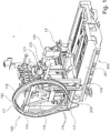
- Fig. 1 shows by way of example a system 1 for changing and inserting or presenting tools in a machine tool 200 in which the tool magazine 110 is configured by way of example as a wheel magazine.
- the machine tool 200 is equipped, for example, with a tool-carrying work spindle 202.
- the machine tool 200 has a machine bed 201 on which a workpiece clamping table can be arranged.
- the machine tool 200 may comprise one or more linear axes, preferably three linear axes (X, Y, and Z axes), in each case for driving a relative translational movement of a tool clamped on the workpiece clamping table relative to a tool clamped to the work spindle 202.
- the machine tool 200 may comprise one or more rotary or swiveling axes, preferably two or three rotary and / or swivel axes, in each case for driving a rotational relative movement of the tool clamped on the workpiece clamping table relative to the tool clamped on the work spindle 202.
- the system 1 comprises a tool magazine 100, which in the embodiment shown here has an annular wheel magazine 110 in which a plurality of tools 101 can be stored for tool storage.
- the tools 101 are supported at an end point 102 along the circumference 111 of the wheel magazine 110.
- the wheel magazine is designed as a ring-shaped hollow cylinder educated.
- tool holders 112 which can form a detachable connection with the tools 101.
- Fig. 1 are the tool holders 112 are arranged as a hole structure along the outer surface of the wheel magazine, which allows a particularly lightweight design.
- the tools are locked in the seats 112 due to centrifugal and gravitational forces.
- an active locking is realized by latching connection with the tools, in which the tools are forcibly locked in a positive connection.
- a self-holding hollow shank cone with face contact HSK
- a steep taper or Morse taper can be used.
- the tools are thus attached only at one of their longitudinal ends on the outer circumference of the wheel magazine 110, so that the tools protrude radially in the radial direction from the outer periphery of the wheel magazine to the outside.
- the longitudinal axes of the tools lie in one plane.
- the tools can be arranged extremely compact and close to each other along the circumference 111 of the wheel magazine 110.
- the wheel magazine 110 can be equipped with all common tools for chipless and cutting production.
- Fig. 1 shows to illustrate the design principle only one assembly with a tool 101.
- the wheel magazine 110 on the one hand, for example, with milling tools and on the other hand with abrasive tools (eg grinding wheels) to be equipped.
- the wheel magazine is mounted by way of example by means of a triangular frame 115, at the three end points of which an impeller 116 is arranged in each case.
- a four- or multi-point bearing is possible.
- the wheel magazine can also be supported by a central axis.
- the rotation of the wheel magazine 110 via a chain drive wherein in Fig. 1 only the drive chain 117 is shown.
- the wheel magazine 110 can also be driven directly via a pinion or via frictional engagement.
- the system 1 further comprises an exemplary horizontally movable manipulator 120 for removing the tools 101 from the tool magazine 100 so that they can be supplied to the tool spindle 202 of the machine tool 200.
- the manipulator 120 can be moved, for example, horizontally between the work spindle 202 and the wheel magazine 110.
- the manipulator 120 illustratively includes a dual gripper 121 having two gripper portions for gripping a tool interface 102 of a tool 101 (e.g., on a gripper groove).
- the machine tool 200 may be a known from the prior art machine tool for cutting or non-cutting production. Particularly advantageous is the system 1 for changing and inserting or presenting tools for universal machining centers, since they must be flexibly equipped with many different tools.
- An arrangement which is as compact as possible is achieved when the tool magazine 100 is attached laterally to the bed 201 and frame 203 in an upright position in order to allow short feed paths of the manipulator 120 to the spindle 202. Due to the possibility of an upright positioning of the wheel magazines 110, the tool changing system can almost always be positioned as close as possible to the spindle, even with different frames and bed shapes.
- the manipulator 120 from the tool magazine 100 is arranged on the outside, ie outside the circumference of the wheel magazine 110 with respect to the unloaded wheel magazine 110, so that it the tools 101 in the direction of the rotary axis of the wheel magazine and / or in the radial direction from the wheel magazine 110 to the outside can take.
- the manipulator schematically shown here comprises a first linear axis, which is adapted to move the manipulator in the direction of the rotary axis of the wheel magazine, that is in the lateral direction to the wheel magazine to perform a horizontal movement between the spindle 202 and wheel magazine 110.
- the manipulator 120 may also have a second linear axis, which is adapted to move the manipulator in the change position on the wheel magazine in the radial direction.
- the manipulator 120 is designed to remove the tools 101 in the illustrated embodiment as a sword changer with double gripper 121, with a left-side and a right-side recording.
- the double gripper 121 allows simultaneous recording of the last used tool and the subsequently required tool, so that a tool exchange with only one horizontal movement of the manipulator 120 between the spindle 202 and tool magazine 110 is possible.
- the tool magazine 100 can optionally be equipped with one or more wheel magazines 110.
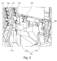
- Fig. 2 schematically shows a detail view of a system for changing and inserting or tools on a machine tool according to an exemplary embodiment of a machine tool.
- Fig. 2 shows, by way of example, two wheel magazines 110 arranged in parallel, at the circumferential tool locations of which tool interfaces 102 (for example, without tools) are held, and the manipulator 120 with the exemplary double gripper 121 (tool gripper).
- a light grid receiver 141 of a tool diameter measuring device 140 which is arranged between the work spindle 202 and the wheel magazine or magazines 110, is arranged on the frame 119 holding the wheel magazines 110.
- a light grating transmitter 142 of the tool diameter measuring device 140 is arranged on the horizontally movable manipulator 120.
- the light grating receiver 141 is exemplarily arranged stationarily on the frame 119 holding the wheel magazines 110 and the light grating transmitter 142 of the tool diameter measuring device 140 is arranged on the movable manipulator 120 by way of example, however, in other embodiments the light grating transmitter 142 the tool diameter measuring device 140 may also be arranged stationarily on the frame 119 holding the wheel magazines 110 and the light grating receiver 141 may be arranged on the movable manipulator 120. In other embodiments, too Light grating receiver 141 and light grid transmitter 142 may be arranged stationarily opposite, such that the manipulator 120 with the tool gripper 121 between light grating receiver 141 and light grating transmitter 142 is movable through.
- the light grating transmitter 142 may emit visible or invisible light (e.g., in the infrared region, and the light grating receiver 141 is configured to detect the light of the grating transmitter 142.
- Fig. 3 schematically shows a front view of a system for changing and inserting tools on a machine tool according to an exemplary embodiment of a machine tool.
- Fig. 3 is on the tool gripper 121 of the manipulator 120 by way of example held a grinding wheel as a tool 101.
- the surface covered in plan view of the light grating receiver 141 and light grating transmitter 142 of the tool diameter measuring device 140 is exemplary in the horizontal direction of the tool magazines 110 to the work spindle 202 of the machine tool 202 in the horizontal direction is traversed by a lower portion of the tool 101 and the grinding wheel.
- a measurement of the tool diameter measuring device 140 takes place at a predetermined position, in particular when the movable part (ie in FIG Fig. 2 eg the light grid transmitter 142) directly to the stationary part (ie in Fig. 2 Eg the light grid receiver 141) is opposite.
- the measuring position is exemplified by a position sensor 143, e.g. can be configured as an induction sensor, determined, and via a movable sensor portion 144, which is arranged on the manipulator 120 and is moved with the manipulator 120, can be detected when the manipulator 120 is positioned at the measuring position.
- a position sensor 143 e.g. can be configured as an induction sensor, determined, and via a movable sensor portion 144, which is arranged on the manipulator 120 and is moved with the manipulator 120, can be detected when the manipulator 120 is positioned at the measuring position.
- the diameter measurement of the tool 110 can be carried out at the measuring position when the manipulator 120 passes through, exactly at a time when it is detected via the movable sensor part 144 and the position sensor 143, that the manipulator is positioned at the measuring position or the manipulator 120 can be stopped when it is detected via the movable sensor part 144 and the position sensor 143 that the manipulator is positioned at the measuring position to the diameter measurement of the tool 110 at the measuring position perform with stopped manipulator 120.
- the diameter measurement of the tool 110 can be performed during replacement of a tool 101 on the work spindle 202, so that additional tool life on the machine tool can advantageously be avoided, as is described, for example. the case would be if the diameter measurement were performed at a designated location in the workspace or on the work spindle. In addition, it is advantageously possible to avoid additional sensors or cameras in the working space of the machine tool 200.
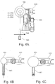
- Figs. 4A, 4B and 4C schematically illustrate a diameter measurement of a tool on a system for changing and loading tools on a machine tool according to an exemplary embodiment on a machine tool.
- the manipulator 120 in the Fig. 4A positioned in the measuring position and thus the movable sensor part 144 is positioned on the position sensor 143 and the position sensor 143 detects that the manipulator 120 is positioned at the measuring position.
- the tool 101 removed from the tool magazine 110 is held on the gripper section of the tool gripper 121 in such a way that the tool 101 (grinding wheels of different diameters are shown) on the measuring surface between the light grating receiver 141 and the light grating transmitter 142 is the tool diameter -Messvorraum 140 is positioned.
- the tool diameter measuring device 140 can thus be activated at this measuring position and the diameter of the tool 101 measured, for example by determining the degree of overlap of the tool 101 with the measuring surface between the light grating receiver 141 and the light grating transmitter 142 of the tool diameter measuring device 140.
- Fig. 4B shows a lower degree of coverage of the tool 101 with the measuring surface between the light grating receiver 141 and the light grating transmitter 142 of the tool diameter measuring device 140 due to a smaller tool diameter of a smaller grinding wheel
- Fig. 4C shows a greater degree of coverage of the tool 101 with the measuring surface between the light grating receiver 141 and the light grating transmitter 142 of the tool diameter measuring device 140 due to a larger tool diameter of a larger grinding wheel.
- light grating receivers 141 and / or light grating transmitters 142 of the tool diameter measuring device 140 can be arranged in a respective transparent housing (eg made of plastic or glass), the advantage being that they are then protected from spray water (eg cooling fluid ) are protected.
- a respective transparent housing eg made of plastic or glass
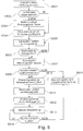
- Fig. 5 shows an exemplary flowchart of a tool change according to an embodiment.
- a tool change is instructed. This can be done on the basis of an NC program running or being executed by the machine control, or on the basis of a command from an operator at the control panel or at the machine control of the machine tool.
- a step S502 it is checked whether a tool type and / or a tool diameter is pre-stored for the tool to be removed. If this is not the case, the operator may be prompted in a step S503 to enter a diameter and / or tool type on the control panel or on the machine control of the machine tool (operator inquiry tool diameter). This is particularly advantageous in grinding tools or grinding wheels.
- a step S504 the manipulator 120 moves to the tool magazine, which holds the tool to be removed and removes the tool to be loaded.
- This may be a milling or drilling tool, or it may also be a grinding tool, such as eg be a grinding wheel.
- the manipulator 120 moves with the tool held in the tool gripper 121 of the manipulator 120 in the direction of the work spindle 202 to the measuring position between the tool magazine and work spindle; Step S505.
- the tool diameter measurement can be carried out at the measuring position between the tool magazine and work spindle in the tool changing process, so that additional service life can be avoided.
- the tool diameter measurement is advantageously carried out in the already scheduled non-productive time of the tool change.
- step S506 is YES
- the measuring device 140 is activated.
- the manipulator 120 can stop briefly or drive through the measuring point when the measuring device 140 is activated.
- step S507 the measurement or determination of the tool diameter of the tool 101 to be loaded takes place at the measuring position by means of the tool diameter measuring device 140, in particular by way of example the light grating receiver 141 and the light grating transmitter 142 of the tool diameter measuring device 140; see in particular Figs. 4A to 4C ,
- step S508 it is determined whether the measured tool diameter (actual diameter) corresponds to the predetermined preset, pre-stored or operator input diameter (target diameter). Alternatively, it may be determined whether the measured or determined tool diameter (actual diameter) falls within a predetermined, pre-set, pre-stored or operator-entered, permissible diameter range.
- step S508 If the check in step S508 is negative, a machining stop on the machine tool can be carried out in a step S509 and / or a warning can be issued to the operator.
- step S508 If the check in step S508 is positive and the measured tool diameter is equal to the predetermined preset, pre-stored or operator entered diameter or diameter range, machining with the workpiece may be enabled.
- an allowable maximum speed S_MAX be set in step S510 on the basis of the tool diameter measured or determined in step S507.
- permissible maximum speeds may be pre-stored in the machine control on the basis of tool diameters and / or tool diameter ranges, wherein larger tool diameters are preferably associated with smaller permissible maximum speeds and smaller tool diameters are preferably associated with larger permissible maximum speeds.
- allowable maximum speeds may be set based on a tool type such that e.g. Grinding tools are associated with smaller allowable maximum speeds than tools with certain cutting edge, such. Milling or drilling tools.
- step S511 the manipulator 120 then moves to the work spindle 202 and performs on the work spindle 202 the tool change in step S512, wherein the measured in step S507 tool 101 on the work spindle 202 is replaced (and optionally there is taken there previously recorded tool to again supplied to the tool magazine).
- step S513 the workpiece machining can be carried out with the substitute tool, wherein in a step S514 it is always checked whether the spindle rotational speed remains below the maximum permissible rotational speed S_MAX, which was set in step S510.
- a machining stop is effected in step S509 and a warning is issued to the operator.
- the checking of the steps S508 and / or S514, which can each lead to a processing stop and / or to a warning to the operator, can be carried out by two redundantly side-by-side devices. So it is e.g. Advantageously possible that the control device or in particular PLC (Program Logic Control, or PLC, programmable logic controller) of the machine tool 200 performs steps S508 and / or S514 and also performs a second, independent safety device steps S508 and / or S514.
- PLC Program Logic Control
- a tool diameter measuring apparatus having a light grid transmitter and a light grid receiver has been proposed.
- the present invention is not limited to tool diameter measuring devices utilizing light curtain transmitters and light curtain receivers. Rather, other optical tool diameter measuring devices may be proposed, e.g. with one or more light barriers or with one or more cameras for the analysis of the tool diameter by optical measurement.
- a system for changing and inserting tools on a machine tool and a machine tool with such a system can be proposed, which efficiently, without downtime and with the required safety allows to use both milling and drilling tools as well as grinding tools on the machine tool.
Landscapes
- Engineering & Computer Science (AREA)
- Mechanical Engineering (AREA)
- Physics & Mathematics (AREA)
- Optics & Photonics (AREA)
- Human Computer Interaction (AREA)
- Manufacturing & Machinery (AREA)
- General Physics & Mathematics (AREA)
- Automation & Control Theory (AREA)
- Automatic Tool Replacement In Machine Tools (AREA)
- Machine Tool Sensing Apparatuses (AREA)
- Numerical Control (AREA)
Applications Claiming Priority (1)
| Application Number | Priority Date | Filing Date | Title |
|---|---|---|---|
| DE102017216447.6A DE102017216447A1 (de) | 2017-09-18 | 2017-09-18 | System zum Wechseln und Einlegen bzw. Vorlegen von Werkzeugen an einer Werkzeugmaschine, und Werkzeugmaschine mit einem derartigen System |
Publications (2)
| Publication Number | Publication Date |
|---|---|
| EP3456470A2 true EP3456470A2 (fr) | 2019-03-20 |
| EP3456470A3 EP3456470A3 (fr) | 2019-05-15 |
Family
ID=63637700
Family Applications (1)
| Application Number | Title | Priority Date | Filing Date |
|---|---|---|---|
| EP18194739.1A Pending EP3456470A3 (fr) | 2017-09-18 | 2018-09-17 | Système de changement et d'insertion ou de fourniture d'outils à une machine-outil et machine-outil dotée d'un tel système |
Country Status (6)
| Country | Link |
|---|---|
| US (1) | US20190084106A1 (fr) |
| EP (1) | EP3456470A3 (fr) |
| JP (1) | JP2019051587A (fr) |
| KR (1) | KR20190032235A (fr) |
| CN (1) | CN109514317A (fr) |
| DE (1) | DE102017216447A1 (fr) |
Cited By (1)
| Publication number | Priority date | Publication date | Assignee | Title |
|---|---|---|---|---|
| EP4474102A1 (fr) * | 2023-06-08 | 2024-12-11 | Pisek - Vitli Krpan, d.o.o. | Machine de coupe ou de séparation avec un ensemble de sécurité pour empêcher une utilisation incorrecte |
Families Citing this family (3)
| Publication number | Priority date | Publication date | Assignee | Title |
|---|---|---|---|---|
| DE102019127052A1 (de) * | 2019-10-08 | 2021-04-08 | Grob-Werke Gmbh & Co. Kg | Verfahren zum Bestimmen von zumindest einer Übergabeposition in einer Werkzeugmaschine und Werkzeugmaschine |
| CN114603638B (zh) * | 2022-04-21 | 2024-01-30 | 深圳市金洲精工科技股份有限公司 | 一种自动化配刀设备及配刀方法 |
| EP4407140B1 (fr) * | 2023-01-26 | 2025-11-12 | Sandvik Mining and Construction Oy | Commande de remplacement d'un outil d'exploitation minière d'un véhicule d'exploitation minière |
Citations (9)
| Publication number | Priority date | Publication date | Assignee | Title |
|---|---|---|---|---|
| JPH0985584A (ja) * | 1995-09-20 | 1997-03-31 | Toshiba Mach Co Ltd | ツールの許容運動速度検出方法および装置およびプログラム機械装置における使用ツール対応運動速度確認方法および装置 |
| JP2000024880A (ja) * | 1998-07-07 | 2000-01-25 | Toshiba Mach Co Ltd | 工具画像の外形認識方法、工具径測定方法及び工具チップの飛散防止方法並びにこれらの装置 |
| EP1087274A2 (fr) * | 1999-09-22 | 2001-03-28 | DECKEL MAHO Pfronten GmbH | Procédé et dispositif de surveillance pour machines-outils à commande numérique |
| DE102005003220A1 (de) * | 2005-01-24 | 2006-08-03 | Gebr. Heller Maschinenfabrik Gmbh | Werkzeugwechseleinrichtung und -verfahren |
| DE102007026517A1 (de) * | 2007-06-08 | 2008-04-24 | Siemens Ag | Schnelldrehende Bearbeitungsmaschine |
| WO2013030373A1 (fr) | 2011-09-02 | 2013-03-07 | Deckel Maho Pfronten Gmbh | Système de changement d'outil sur une machine-outil |
| DE102014205346A1 (de) * | 2013-03-22 | 2014-09-25 | Dmg Mori Seiki Co., Ltd. | Werkzeugwechselsystem und -verfahren |
| DE202017000560U1 (de) | 2017-02-02 | 2017-02-13 | Deckel Maho Pfronten Gmbh | Werkzeughalter zur Aufnahme eines Schleifwerkzeugs zur schleifenden Bearbeitung eines Werkstücks an einer numerisch gesteuerten Werkzeugmaschine mit werkzeugtragender Arbeitsspindel |
| EP3203333A1 (fr) * | 2014-09-30 | 2017-08-09 | Makino Milling Machine Co., Ltd. | Dispositif de commande pour machine-outil et machine-outil |
Family Cites Families (4)
| Publication number | Priority date | Publication date | Assignee | Title |
|---|---|---|---|---|
| JPH0523943A (ja) * | 1991-06-10 | 1993-02-02 | O M Ltd | 工具自動配給装置 |
| JP2003136372A (ja) * | 2001-08-20 | 2003-05-14 | Okuma Corp | 工具寸法の自動計測方法及び装置 |
| US7266420B2 (en) * | 2004-04-03 | 2007-09-04 | Gerald Walter Budd | Automatic detection system for broken tools in CNC machining centers using advanced machine vision techniques |
| JP4970761B2 (ja) * | 2004-10-08 | 2012-07-11 | オークマ株式会社 | 工具交換装置及びこれを備えた工作機械 |
-
2017
- 2017-09-18 DE DE102017216447.6A patent/DE102017216447A1/de active Pending
-
2018
- 2018-09-13 JP JP2018171383A patent/JP2019051587A/ja not_active Ceased
- 2018-09-17 EP EP18194739.1A patent/EP3456470A3/fr active Pending
- 2018-09-18 KR KR1020180111524A patent/KR20190032235A/ko not_active Withdrawn
- 2018-09-18 CN CN201811089711.5A patent/CN109514317A/zh active Pending
- 2018-09-18 US US16/134,182 patent/US20190084106A1/en not_active Abandoned
Patent Citations (9)
| Publication number | Priority date | Publication date | Assignee | Title |
|---|---|---|---|---|
| JPH0985584A (ja) * | 1995-09-20 | 1997-03-31 | Toshiba Mach Co Ltd | ツールの許容運動速度検出方法および装置およびプログラム機械装置における使用ツール対応運動速度確認方法および装置 |
| JP2000024880A (ja) * | 1998-07-07 | 2000-01-25 | Toshiba Mach Co Ltd | 工具画像の外形認識方法、工具径測定方法及び工具チップの飛散防止方法並びにこれらの装置 |
| EP1087274A2 (fr) * | 1999-09-22 | 2001-03-28 | DECKEL MAHO Pfronten GmbH | Procédé et dispositif de surveillance pour machines-outils à commande numérique |
| DE102005003220A1 (de) * | 2005-01-24 | 2006-08-03 | Gebr. Heller Maschinenfabrik Gmbh | Werkzeugwechseleinrichtung und -verfahren |
| DE102007026517A1 (de) * | 2007-06-08 | 2008-04-24 | Siemens Ag | Schnelldrehende Bearbeitungsmaschine |
| WO2013030373A1 (fr) | 2011-09-02 | 2013-03-07 | Deckel Maho Pfronten Gmbh | Système de changement d'outil sur une machine-outil |
| DE102014205346A1 (de) * | 2013-03-22 | 2014-09-25 | Dmg Mori Seiki Co., Ltd. | Werkzeugwechselsystem und -verfahren |
| EP3203333A1 (fr) * | 2014-09-30 | 2017-08-09 | Makino Milling Machine Co., Ltd. | Dispositif de commande pour machine-outil et machine-outil |
| DE202017000560U1 (de) | 2017-02-02 | 2017-02-13 | Deckel Maho Pfronten Gmbh | Werkzeughalter zur Aufnahme eines Schleifwerkzeugs zur schleifenden Bearbeitung eines Werkstücks an einer numerisch gesteuerten Werkzeugmaschine mit werkzeugtragender Arbeitsspindel |
Cited By (1)
| Publication number | Priority date | Publication date | Assignee | Title |
|---|---|---|---|---|
| EP4474102A1 (fr) * | 2023-06-08 | 2024-12-11 | Pisek - Vitli Krpan, d.o.o. | Machine de coupe ou de séparation avec un ensemble de sécurité pour empêcher une utilisation incorrecte |
Also Published As
| Publication number | Publication date |
|---|---|
| CN109514317A (zh) | 2019-03-26 |
| DE102017216447A8 (de) | 2019-06-27 |
| JP2019051587A (ja) | 2019-04-04 |
| EP3456470A3 (fr) | 2019-05-15 |
| DE102017216447A1 (de) | 2019-03-21 |
| US20190084106A1 (en) | 2019-03-21 |
| KR20190032235A (ko) | 2019-03-27 |
Similar Documents
| Publication | Publication Date | Title |
|---|---|---|
| EP3456470A2 (fr) | Système de changement et d'insertion ou de fourniture d'outils à une machine-outil et machine-outil dotée d'un tel système | |
| AT506365B1 (de) | Kuppeleinrichtung und verfahren zum automatisierten ankuppeln eines werkzeughalters an einen werkzeugaufnehmer auf einer handhabungseinrichtung | |
| DE102018104378B4 (de) | Werkzeugmaschine | |
| DE69627204T2 (de) | Indexierapparat und verfahren zu seinem antrieb | |
| DE102017008151A1 (de) | Flüssigkeitsausstoss-Vorrichtung | |
| DE102017110035A1 (de) | Werkzeugmaschine | |
| EP3453486A1 (fr) | Dispositif d'usinage d'une pièce à usiner à l'aide d'un outil | |
| EP0804983B1 (fr) | Outil avec capteur | |
| DE102020105752A1 (de) | Werkzeugmaschine, Bearbeitungssystem und Verwaltungssystem | |
| DE102008004851A1 (de) | Vorrichtung zum Bearbeiten, insbesondere Erodieren und Schleifen, von mit Schneiden versehenen Rotationsstücken | |
| DE3941756C2 (fr) | ||
| DE3702424C2 (fr) | ||
| DE3247586C2 (fr) | ||
| EP2216697A1 (fr) | Machine outil et procédé pour éviter une collision dans une machine outil | |
| EP0268622A1 (fr) | Procede, appareil de mesure, porte-outil reglable avec precision et dispositif compensateur pour le controle de qualite en cours d'operation de machines-outils d'usinage | |
| DE1602774C3 (de) | Vorrichtung zur wahlweisen Befestigung eines Spannfutters an der Spindel einer Werkzeugmaschine oder an einer Futterwechselscheibe und Spannfutter hierzu | |
| EP3933526B1 (fr) | Procédé de surveillance et de commande d'une machine-outil et machine-outil | |
| DE3634018C2 (fr) | ||
| DE102017001297A1 (de) | Vorrichtung zum Indexieren einer Spindelphase für eine Werkzeugmaschine | |
| DE102008004849B4 (de) | Vorrichtung und Verfahren zum Bearbeiten von Werkstücken | |
| DE2610185C3 (de) | Maschine mit mehreren Bearbeitungsköpfen, insbesondere zur spanabhebenden Bearbeitung eines Werkstückes | |
| DE102014221725B3 (de) | Verfahren zur Herstellung einer Schrägfläche mittels einer Drehmaschine und Drehmaschine | |
| DE69627896T2 (de) | Indexierapparat und verfahren zu seiner steuerung | |
| DE3108071C2 (fr) | ||
| EP4501505A2 (fr) | Machine-outil avec un porte-outil mobile, porte-outil et porte-outil pour cette machine-outil |
Legal Events
| Date | Code | Title | Description |
|---|---|---|---|
| PUAI | Public reference made under article 153(3) epc to a published international application that has entered the european phase |
Free format text: ORIGINAL CODE: 0009012 |
|
| STAA | Information on the status of an ep patent application or granted ep patent |
Free format text: STATUS: THE APPLICATION HAS BEEN PUBLISHED |
|
| AK | Designated contracting states |
Kind code of ref document: A2 Designated state(s): AL AT BE BG CH CY CZ DE DK EE ES FI FR GB GR HR HU IE IS IT LI LT LU LV MC MK MT NL NO PL PT RO RS SE SI SK SM TR |
|
| AX | Request for extension of the european patent |
Extension state: BA ME |
|
| PUAL | Search report despatched |
Free format text: ORIGINAL CODE: 0009013 |
|
| AK | Designated contracting states |
Kind code of ref document: A3 Designated state(s): AL AT BE BG CH CY CZ DE DK EE ES FI FR GB GR HR HU IE IS IT LI LT LU LV MC MK MT NL NO PL PT RO RS SE SI SK SM TR |
|
| AX | Request for extension of the european patent |
Extension state: BA ME |
|
| RIC1 | Information provided on ipc code assigned before grant |
Ipc: G05B 19/406 20060101ALI20190411BHEP Ipc: B23Q 17/24 20060101AFI20190411BHEP Ipc: B23Q 3/155 20060101ALI20190411BHEP |
|
| STAA | Information on the status of an ep patent application or granted ep patent |
Free format text: STATUS: REQUEST FOR EXAMINATION WAS MADE |
|
| 17P | Request for examination filed |
Effective date: 20191115 |
|
| RBV | Designated contracting states (corrected) |
Designated state(s): AL AT BE BG CH CY CZ DE DK EE ES FI FR GB GR HR HU IE IS IT LI LT LU LV MC MK MT NL NO PL PT RO RS SE SI SK SM TR |
|
| STAA | Information on the status of an ep patent application or granted ep patent |
Free format text: STATUS: EXAMINATION IS IN PROGRESS |
|
| 17Q | First examination report despatched |
Effective date: 20200529 |
|
| RAP3 | Party data changed (applicant data changed or rights of an application transferred) |
Owner name: DMG MORI PFRONTEN GMBH |