EP3462251A1 - Stellmechanismus für uhrwerk - Google Patents
Stellmechanismus für uhrwerk Download PDFInfo
- Publication number
- EP3462251A1 EP3462251A1 EP17193963.0A EP17193963A EP3462251A1 EP 3462251 A1 EP3462251 A1 EP 3462251A1 EP 17193963 A EP17193963 A EP 17193963A EP 3462251 A1 EP3462251 A1 EP 3462251A1
- Authority
- EP
- European Patent Office
- Prior art keywords
- locking
- wheel
- setting
- sliding pinion
- time
- Prior art date
- Legal status (The legal status is an assumption and is not a legal conclusion. Google has not performed a legal analysis and makes no representation as to the accuracy of the status listed.)
- Granted
Links
Images

Classifications
-
- G—PHYSICS
- G04—HOROLOGY
- G04B—MECHANICALLY-DRIVEN CLOCKS OR WATCHES; MECHANICAL PARTS OF CLOCKS OR WATCHES IN GENERAL; TIME PIECES USING THE POSITION OF THE SUN, MOON OR STARS
- G04B27/00—Mechanical devices for setting the time indicating means
- G04B27/02—Mechanical devices for setting the time indicating means by making use of the winding means
-
- G—PHYSICS
- G04—HOROLOGY
- G04B—MECHANICALLY-DRIVEN CLOCKS OR WATCHES; MECHANICAL PARTS OF CLOCKS OR WATCHES IN GENERAL; TIME PIECES USING THE POSITION OF THE SUN, MOON OR STARS
- G04B27/00—Mechanical devices for setting the time indicating means
-
- G—PHYSICS
- G04—HOROLOGY
- G04B—MECHANICALLY-DRIVEN CLOCKS OR WATCHES; MECHANICAL PARTS OF CLOCKS OR WATCHES IN GENERAL; TIME PIECES USING THE POSITION OF THE SUN, MOON OR STARS
- G04B27/00—Mechanical devices for setting the time indicating means
- G04B27/02—Mechanical devices for setting the time indicating means by making use of the winding means
- G04B27/04—Mechanical devices for setting the time indicating means by making use of the winding means with clutch wheel
- G04B27/045—Changing the winding position to the setting position and vice versa is done with an independant part of the winding or setting mechanism
-
- G—PHYSICS
- G04—HOROLOGY
- G04B—MECHANICALLY-DRIVEN CLOCKS OR WATCHES; MECHANICAL PARTS OF CLOCKS OR WATCHES IN GENERAL; TIME PIECES USING THE POSITION OF THE SUN, MOON OR STARS
- G04B13/00—Gearwork
-
- G—PHYSICS
- G04—HOROLOGY
- G04B—MECHANICALLY-DRIVEN CLOCKS OR WATCHES; MECHANICAL PARTS OF CLOCKS OR WATCHES IN GENERAL; TIME PIECES USING THE POSITION OF THE SUN, MOON OR STARS
- G04B27/00—Mechanical devices for setting the time indicating means
- G04B27/02—Mechanical devices for setting the time indicating means by making use of the winding means
- G04B27/04—Mechanical devices for setting the time indicating means by making use of the winding means with clutch wheel
-
- G—PHYSICS
- G04—HOROLOGY
- G04B—MECHANICALLY-DRIVEN CLOCKS OR WATCHES; MECHANICAL PARTS OF CLOCKS OR WATCHES IN GENERAL; TIME PIECES USING THE POSITION OF THE SUN, MOON OR STARS
- G04B3/00—Normal winding of clockworks by hand or mechanically; Winding up several mainsprings or driving weights simultaneously
- G04B3/04—Rigidly-mounted keys, knobs or crowns
-
- G—PHYSICS
- G04—HOROLOGY
- G04B—MECHANICALLY-DRIVEN CLOCKS OR WATCHES; MECHANICAL PARTS OF CLOCKS OR WATCHES IN GENERAL; TIME PIECES USING THE POSITION OF THE SUN, MOON OR STARS
- G04B37/00—Cases
- G04B37/06—Forming the passage for the winding stem through the case; Divided winding stems
- G04B37/062—Means for preventing the winding stem from being pulled out too far
- G04B37/064—Means for preventing the winding stem from being pulled out too far by a tirette
Definitions
- the present invention relates to a time-setting mechanism for a clockwork movement of a watch comprising a locking device of the time setting wheel in order to avoid a movement of the needles in the event of shocks.
- a friction system is generally provided for this purpose in order to guarantee an easy adjustment of the time while ensuring a reliable drive of the needles by the finishing gear during the running of the watch.
- a well-known friction system is the skylight which consists of adjusting the roadway on the center pinion shaft in order to obtain a "greasy friction" to allow time setting without causing the finishing gear.
- the thickness of the roadway is reduced in the middle and is pinched by means of a dedicated tool for this purpose so as to form a projection which press against a conical cut of the pinion shaft of the center.
- Lanterning is a delicate operation that requires careful control to ensure that the torque value generated by friction between the roadway and the center pinion shaft is optimal. Indeed, a low friction torque can cause, during shocks, a displacement of the needles due to their unbalance. By the way, a couple too strong may cause the deterioration of the time-setting train (idle-sprint-timer-gear) or the work train (center-medium-second-exhaust) during the time setting.
- the object of the present invention is to provide a time-setting mechanism in order, in particular, to overcome the disadvantages of the prior art mentioned above and to avoid any drift in the display of the time during shocks. important to the watch.
- the time setting mechanism further comprises a locking device of the time setting wheel.
- This locking device comprises a first and second locking arm and a locking wheel engaged with the time setting train.
- the first and second locking arms are arranged, on the one hand, to engage with the locking wheel in a so-called locked configuration in which the time setting gear is locked and, on the other hand, to be released from the locking wheel in a so-called unlocked configuration in which the sliding pinion is free to mesh with the time setting wheel.
- the blocking device comprises a latching / unlocking lever engaged with the sliding pinion and arranged to cooperate with the first and second locking arms in order to effect a transition from the locked configuration to the unlocked configuration and vice versa when the winding stem is brought from a running position to a setting position and vice versa.
- the locking wheel comprises a toothing whose apex of each tooth has a curved profile.
- the first and second locking arms each comprise a portion having a curved edge provided with a micro-tooth.
- the radius of curvature of the curved edge of the first and second locking arms substantially corresponds to the radius of the head circle of the locking wheel.
- These micro teeth are intended to come into contact with the toothing of the locking wheel in the locked configuration of the locking device.
- the particular profile of the toothing of the locking wheel and micro-teeth has the advantage of allowing an angular precision of locking of the wheel so that the deviation of the needles is negligible after correction of the time when the rod of winder is brought back into the walking position.
- the micro teeth of the first and second locking arms are symmetrical relative to each other so as to prevent rotation of the locking wheel in both directions.
- first and second locking arms are superposed and pivotally mounted relative to one another about a common axis.
- the curved edge of the lower or upper locking arm is respectively intended to come into contact with a lower or upper portion of the toothing of the locking wheel.
- one or both arms of blocking may include an extra thickness in the portion comprising the micro teeth arranged so as to provide support of the two arms of the same height on the locking wheel.
- the latching / unlocking latch is arranged to pivot about a pivot when the winding stem is brought from a running position to a setting position and vice versa.
- This latch / unlocking latch has two arms extending on either side of the pivot. One end of one of the two arms is engaged with the sliding pinion while the other of the two arms has a distal portion intended to cooperate with the upper locking arm and a proximal portion intended to cooperate with the lower locking arm.
- the distal portion bears against a straight flank of the upper locking arm.
- the proximal portion for its part, bears or is intended to bear against an actuating element, preferably a pin, of the lower locking arm in order to disengage the locking arms from the toothing of the locking wheel.
- an actuating element preferably a pin
- the locking wheel is the timer wheel of the time setting wheel.
- the locking wheel is mounted integral with the axis of a standard timer wheel of the time setting wheel.
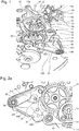
- the time setting mechanism comprises, in a conventional manner, a pull tab 12 comprising a pin 12a housed in a recess of the winding stem 10, a rocker 14 arranged to cooperate with the pull tab 12, and a sliding pinion 16. It is fitted on a segment 17a of square cross section of a secondary rod 17 so as to be able to move along this segment 17a of a first axial position, in which the sliding pinion 16 is a socket with a pinion 18, at a second axial position, in which the sliding pinion 16 is engaged with a return 19 of the time-setting train as illustrated in FIG. figure 2b .
- the latch 14 has an end 14a arranged in a circular groove 16a of the sliding pinion 16.
- the pull tab 12 pivots and pushes back the rocker 14 which slides the sliding pinion 16 along the segment 17a of the secondary rod 17.
- the sliding pinion 16 thus disengages the pinion winding 18 to engage with the reference 19 of the time setting train for the control of the needles.
- the time setting mechanism further comprises a blocking device time setting.
- This device comprises a locking wheel 20 configured to cooperate on the one hand with the time setting train and secondly with a first and second locking arm 22, 30.
- the locking wheel 20 has a toothing whose apex of each tooth has a curved profile.
- This particular profile of the toothing of the blocking wheel 20 makes it possible, on the one hand, to maintain a toothing allowing meshing with the sliding pinion 16 via the returns for setting the time, in order to fulfill the function of a standard timer wheel, and on the other hand, to increase the angular accuracy of the locking by the first and second locking arms 22, 30.
- these latter each comprise a portion 28, 32 having a curved edge extending in an arc of an angle preferably between 30 ° and 40 °, whose radius of curvature essentially corresponds to the radius of the head circle of the locking wheel 20.
- the curved edges of the locking arms 22, 30 are provided with micro-teeth to increase the points of contact with the toothing of the locking wheel 20 when the curved edges are in contact with the latter. . This has the advantage of increasing the angular accuracy of the blockage.
- the first and second locking arms 22, 30 are also superimposed and pivotally mounted relative to each other around a post 36.
- the micro teeth of the upper locking arm 22 and the lower locking arm 30 are held against an upper portion, respectively lower of the toothing of the locking wheel 20 by a spring (220 and 300), when the locking device is in a locked configuration.
- These two micro-teeth have a symmetry with respect to an axis passing through the center of the locking wheel 20 and by the pivot axis of the two locking arms 22, 30. The two micro-teeth are therefore oriented in an opposite direction.
- the first locking arm 22 has a spout 26 provided with a straight blank 24 from the tip of the spout 26 to a corner 25 forming an obtuse angle.
- the second locking arm 30 comprises, meanwhile, a pin 34 extending vertically relative to the plane in which the second arm is arranged to pivot
- the blocking device of the time-setting train furthermore comprises a latch / unlocking latch 40 intended to lock and unlock the locking wheel 20.
- this latch / unlocking latch 40 is arranged to pivot around it.
- a post 46 and comprises two arms 42, 44 extending on either side of the post 46.
- One end of one of the two arms 42 is housed in the circular groove 16a of the sliding pinion 16 facing the end. 14a of the latch 14.
- the end of the arm 42 of the latch latch / unlocking 40 and the end 14a of the latch 14 are arranged on either side of a rod connecting the part sliding pinion 16 intended to mesh with the reference 19 and the part of the sliding pinion 16 intended to mesh with the winding pinion 18.
- the other of the two arms 44 of the latch / unlock latch 40 is similar to an angled arm having a distal portion 44a and a proximal portion 44b ( figure 2a ).
- the distal portion 44a has a pointed end located in the corner 45 of the first locking arm 22 when the locking device of the time-setting train is in a locked configuration.
- the proximal portion 44b is intended to abut against the pin 34 of the second locking arm 30 when the winding stem 10 is brought into a setting position.
- the blocking device of the time-setting train is in a locked configuration, that is to say the blocking wheel 20 is locked by the first and second locking arms 22, thus guaranteeing the blocking of the locking mechanism.
- clocking mechanism in case of big shocks on the watch and this during the normal running of the watch.
- the winding stem 10 When it is necessary to perform a time setting, the winding stem 10 is brought from a first axial position corresponding to a running position of the watch to a second axial position corresponding to a setting position. time of the watch.
- the axial displacement of the winding stem 10 actuates the pull rod 12 in rotation, which in turn actuates the rocker 14 so that its end 14a moves the sliding pinion 16 along the segment 17a of the secondary rod 17 of a first position axial, in which it is engaged with the winding pinion 18 at a second axial position, in which it is engaged with the reference 19 of the gear train time setting.
- the arms 42, 44 of the latch / unlock latch 40 pivot about the pin 46 counterclockwise under the action of the sliding pinion 16 on the end of the arm 42 when it moves from its position. first position at its second axial position.
- the pointed end of the distal portion 44a of the arm 44 will exert a stress on the rectilinear flank 24 of the first arm 22, while moving along this side 24 so that the first arm 22 pivots around the pin 36 so as to release the first micro gear of the locking wheel 20.
- the proximal portion 44b abuts against the pin 34 of the second locking arm 30 to release the second micro-teeth of the locking wheel 20.
- the locking device as illustrated in figure 2b is in an unlocked configuration and the time setting has the advantage of being able to be done without risk of damaging the finishing gear because, as mentioned above, the roadway is simply adjusted to the barrel of the minute wheel without any "Greasy friction".
- the winding stem 10 is returned to the first axial position, and the latch / unlocking lever 40 pivots around its peg 46 in a clockwise direction, which brings the arm 44 back into position. position illustrated in the figure 2a .
- the first and second coupling arms 22, 30 pivot about the pin 36 under the action of their respective return spring in order to bring and maintain their respective micro teeth against the toothing of the locking wheel 20 thus locking the locking device so that the watch is insensitive to any significant shocks.
- the locking wheel 20 could only perform the blocking function of the time setting wheel without fulfilling the function of the timer wheel. It could therefore have a locking wheel mounted to the axis of a standard timer wheel, and blocked by the two locking arms. The toothing of the locking wheel will then be solely dedicated to cooperate with the teeth of the locking arms and the number of teeth may be increased to improve the angular accuracy of the locking.
- the sliding pinion is adjusted to move on a segment of a secondary rod off-set relative to the winding stem.
- this construction is dictated by the constraints of a particular watchmaking movement.
Landscapes
- Physics & Mathematics (AREA)
- General Physics & Mathematics (AREA)
- Electromechanical Clocks (AREA)
- Measurement Of Predetermined Time Intervals (AREA)
- Transmission Devices (AREA)
- Mechanical Operated Clutches (AREA)
- Telephone Set Structure (AREA)
Priority Applications (4)
| Application Number | Priority Date | Filing Date | Title |
|---|---|---|---|
| EP17193963.0A EP3462251B1 (de) | 2017-09-29 | 2017-09-29 | Stellmechanismus für uhrwerk |
| US16/104,180 US10955799B2 (en) | 2017-09-29 | 2018-08-17 | Setting mechanism for timepiece movement |
| JP2018173313A JP6547048B2 (ja) | 2017-09-29 | 2018-09-18 | 計時器用ムーブメントのためのセッティング機構 |
| CN201811139626.5A CN109581852B (zh) | 2017-09-29 | 2018-09-28 | 用于钟表机芯的拨针机构 |
Applications Claiming Priority (1)
| Application Number | Priority Date | Filing Date | Title |
|---|---|---|---|
| EP17193963.0A EP3462251B1 (de) | 2017-09-29 | 2017-09-29 | Stellmechanismus für uhrwerk |
Publications (2)
| Publication Number | Publication Date |
|---|---|
| EP3462251A1 true EP3462251A1 (de) | 2019-04-03 |
| EP3462251B1 EP3462251B1 (de) | 2020-06-10 |
Family
ID=59997218
Family Applications (1)
| Application Number | Title | Priority Date | Filing Date |
|---|---|---|---|
| EP17193963.0A Active EP3462251B1 (de) | 2017-09-29 | 2017-09-29 | Stellmechanismus für uhrwerk |
Country Status (4)
| Country | Link |
|---|---|
| US (1) | US10955799B2 (de) |
| EP (1) | EP3462251B1 (de) |
| JP (1) | JP6547048B2 (de) |
| CN (1) | CN109581852B (de) |
Cited By (1)
| Publication number | Priority date | Publication date | Assignee | Title |
|---|---|---|---|---|
| EP4538804A1 (de) * | 2023-10-10 | 2025-04-16 | Montres Breguet S.A. | Komponente einer uhrwerk, die ein verriegelbares gelenk umfasst |
Families Citing this family (2)
| Publication number | Priority date | Publication date | Assignee | Title |
|---|---|---|---|---|
| CN113653799B (zh) * | 2021-09-01 | 2022-08-12 | 西安轻工业钟表研究所有限公司 | 一种可自保险的解锁机构 |
| CN114488756B (zh) * | 2022-03-03 | 2025-06-20 | 天津精诚拓飞科技有限公司 | 一种机芯倒拨针脱开机构 |
Citations (7)
| Publication number | Priority date | Publication date | Assignee | Title |
|---|---|---|---|---|
| CH237215A (fr) * | 1943-12-20 | 1945-04-15 | Sa A Schild | Mouvement de montre à remontoir. |
| JPS4962457U (de) * | 1972-09-13 | 1974-05-31 | ||
| GB2071364A (en) * | 1980-02-12 | 1981-09-16 | Citizen Watch Co Ltd | Correction system for electronic timepiece with both analog and digital displays |
| JPH02683U (de) * | 1988-06-10 | 1990-01-05 | ||
| EP1367462A1 (de) * | 2002-05-28 | 2003-12-03 | Ulysse Nardin S.A. | Hemmung für Uhren |
| WO2007115984A2 (fr) * | 2006-04-07 | 2007-10-18 | Frederic Piguet S.A. | Piece d'horlogerie comprenant un mecanisme a deux fuseaux horaires |
| CH704331A1 (fr) * | 2011-01-13 | 2012-07-13 | Greubel Forsey S A | Pièce d'horlogerie. |
Family Cites Families (12)
| Publication number | Priority date | Publication date | Assignee | Title |
|---|---|---|---|---|
| CH640686B (fr) * | 1980-10-23 | Ebauchesfabrik Eta Ag | Dispositif de commande coulissant pour montre. | |
| FR2750513B1 (fr) * | 1996-06-26 | 1998-08-07 | Ebauchesfabrik Eta Ag | Piece d'horlogerie avec mecanisme de mise a l'heure par action directe de la tirette |
| CN2610371Y (zh) * | 2003-03-31 | 2004-04-07 | 陈毅力 | 一种钟表拨针机构 |
| DE602006001298D1 (de) * | 2006-05-31 | 2008-07-03 | Montres Breguet Sa | Uhr, die eine verbesserte Vorrichtung zur Zeiteinstellung umfasst |
| DE602007003075D1 (de) * | 2007-04-18 | 2009-12-17 | Eta Sa Mft Horlogere Suisse | Ankerhemmung, die zwei Hemmungszahnräder umfasst |
| DE602007003445D1 (de) * | 2007-04-18 | 2010-01-07 | Eta Sa Mft Horlogere Suisse | Hemmung, die zwei Hemmungsräder umfasst |
| CN102262390B (zh) * | 2010-05-28 | 2012-11-21 | 天津海鸥表业集团有限公司 | 一种手表上条拨针转换机构 |
| EP2487546B1 (de) * | 2011-02-11 | 2021-06-30 | Montres Journe S.A. | Zweiachsige Hochleistungshemmung |
| EP2565728B1 (de) * | 2011-08-29 | 2018-05-09 | ETA SA Manufacture Horlogère Suisse | Autonomer Steuermechanismus für ein Uhrenteil |
| CN103048911B (zh) * | 2011-10-13 | 2014-12-17 | 天津海鸥表业集团有限公司 | 一种机械钟表的上条与拨针机构 |
| JP5961753B2 (ja) * | 2012-06-07 | 2016-08-02 | デトラ ソシエテ アノニム | 時計用脱進装置 |
| CN202995270U (zh) * | 2012-12-12 | 2013-06-12 | 天王电子(深圳)有限公司 | 一种机械手表及机械手表的上条拨针机构 |
-
2017
- 2017-09-29 EP EP17193963.0A patent/EP3462251B1/de active Active
-
2018
- 2018-08-17 US US16/104,180 patent/US10955799B2/en active Active
- 2018-09-18 JP JP2018173313A patent/JP6547048B2/ja active Active
- 2018-09-28 CN CN201811139626.5A patent/CN109581852B/zh active Active
Patent Citations (7)
| Publication number | Priority date | Publication date | Assignee | Title |
|---|---|---|---|---|
| CH237215A (fr) * | 1943-12-20 | 1945-04-15 | Sa A Schild | Mouvement de montre à remontoir. |
| JPS4962457U (de) * | 1972-09-13 | 1974-05-31 | ||
| GB2071364A (en) * | 1980-02-12 | 1981-09-16 | Citizen Watch Co Ltd | Correction system for electronic timepiece with both analog and digital displays |
| JPH02683U (de) * | 1988-06-10 | 1990-01-05 | ||
| EP1367462A1 (de) * | 2002-05-28 | 2003-12-03 | Ulysse Nardin S.A. | Hemmung für Uhren |
| WO2007115984A2 (fr) * | 2006-04-07 | 2007-10-18 | Frederic Piguet S.A. | Piece d'horlogerie comprenant un mecanisme a deux fuseaux horaires |
| CH704331A1 (fr) * | 2011-01-13 | 2012-07-13 | Greubel Forsey S A | Pièce d'horlogerie. |
Cited By (1)
| Publication number | Priority date | Publication date | Assignee | Title |
|---|---|---|---|---|
| EP4538804A1 (de) * | 2023-10-10 | 2025-04-16 | Montres Breguet S.A. | Komponente einer uhrwerk, die ein verriegelbares gelenk umfasst |
Also Published As
| Publication number | Publication date |
|---|---|
| JP6547048B2 (ja) | 2019-07-17 |
| JP2019066469A (ja) | 2019-04-25 |
| US20190101867A1 (en) | 2019-04-04 |
| CN109581852B (zh) | 2020-12-11 |
| CN109581852A (zh) | 2019-04-05 |
| EP3462251B1 (de) | 2020-06-10 |
| US10955799B2 (en) | 2021-03-23 |
Similar Documents
| Publication | Publication Date | Title |
|---|---|---|
| EP1983389B1 (de) | Hemmung, die zwei Hemmungsräder umfasst | |
| EP3059643B1 (de) | Uhrmechanismus | |
| EP1152303B1 (de) | Uhr mit Aufzugsmechanismus und mit Korrekturmechanismus für mindestens zwei anzeigende Organe | |
| EP3483663B1 (de) | Antriebsvorrichtung für kalendersystem einer uhr | |
| EP3462251B1 (de) | Stellmechanismus für uhrwerk | |
| EP2503412B1 (de) | Timepiece movement comprising a device with running time equation | |
| EP3070537A1 (de) | Zeitbasiseinheit, die eine hemmung mit direktimpuls und konstanter kraft umfasst | |
| EP3059642B1 (de) | Uhrmechanismus | |
| EP3430481A1 (de) | Uhrwerk mit einer rückläufigen anzeige und einem sprungstundenring | |
| EP3489766B1 (de) | Mechanismus zur korrektur einer bewegungsfunktion einer uhr | |
| EP3955066B1 (de) | Armbanduhr, die einen steuermechanismus mit aufzugswelle und stellhebel umfasst | |
| CH714199A2 (fr) | Mécanisme de mise à l'heure pour mouvement horloger. | |
| EP2884345B1 (de) | Hebelfeder für uhrwerk | |
| EP1801671A1 (de) | Mit Arretierungsmitteln versehene Kalenderuhr | |
| EP3206088A1 (de) | Hemmungsmechanismus | |
| EP4053639B1 (de) | Vorrichtung zur auswahl von uhrfunktionen | |
| EP2241945B1 (de) | Chronographenmechanismus und mit diesem Mechanismus ausgerüstete Uhr | |
| EP2339414B1 (de) | Chronograph mit einem einzigen Drücker | |
| EP3408712B1 (de) | Datumsmechanismus | |
| EP0871095B1 (de) | Anzeigevorrichtung mit springendem Sekundenzeiger | |
| EP4053640B1 (de) | Vorrichtung zur auswahl von uhrfunktionen | |
| EP3786724A1 (de) | Stossdämpfungs- und/oder anti-doppelsprung-mechanismus für uhrwerk einer uhr | |
| EP4312088B1 (de) | Vorrichtung mit versenkbarem finger zum betätigen eines uhrwerkmechanismus | |
| EP4325303A1 (de) | Mechanismus eines immerwährenden kalenders mit konzentrischen nocken | |
| EP3800512B1 (de) | On-demand-anzeigevorrichtung für uhr |
Legal Events
| Date | Code | Title | Description |
|---|---|---|---|
| PUAI | Public reference made under article 153(3) epc to a published international application that has entered the european phase |
Free format text: ORIGINAL CODE: 0009012 |
|
| STAA | Information on the status of an ep patent application or granted ep patent |
Free format text: STATUS: THE APPLICATION HAS BEEN PUBLISHED |
|
| AK | Designated contracting states |
Kind code of ref document: A1 Designated state(s): AL AT BE BG CH CY CZ DE DK EE ES FI FR GB GR HR HU IE IS IT LI LT LU LV MC MK MT NL NO PL PT RO RS SE SI SK SM TR |
|
| AX | Request for extension of the european patent |
Extension state: BA ME |
|
| STAA | Information on the status of an ep patent application or granted ep patent |
Free format text: STATUS: REQUEST FOR EXAMINATION WAS MADE |
|
| 17P | Request for examination filed |
Effective date: 20191004 |
|
| RBV | Designated contracting states (corrected) |
Designated state(s): AL AT BE BG CH CY CZ DE DK EE ES FI FR GB GR HR HU IE IS IT LI LT LU LV MC MK MT NL NO PL PT RO RS SE SI SK SM TR |
|
| GRAP | Despatch of communication of intention to grant a patent |
Free format text: ORIGINAL CODE: EPIDOSNIGR1 |
|
| STAA | Information on the status of an ep patent application or granted ep patent |
Free format text: STATUS: GRANT OF PATENT IS INTENDED |
|
| INTG | Intention to grant announced |
Effective date: 20200114 |
|
| GRAS | Grant fee paid |
Free format text: ORIGINAL CODE: EPIDOSNIGR3 |
|
| GRAA | (expected) grant |
Free format text: ORIGINAL CODE: 0009210 |
|
| STAA | Information on the status of an ep patent application or granted ep patent |
Free format text: STATUS: THE PATENT HAS BEEN GRANTED |
|
| AK | Designated contracting states |
Kind code of ref document: B1 Designated state(s): AL AT BE BG CH CY CZ DE DK EE ES FI FR GB GR HR HU IE IS IT LI LT LU LV MC MK MT NL NO PL PT RO RS SE SI SK SM TR |
|
| REG | Reference to a national code |
Ref country code: GB Ref legal event code: FG4D Free format text: NOT ENGLISH |
|
| REG | Reference to a national code |
Ref country code: CH Ref legal event code: EP Ref country code: AT Ref legal event code: REF Ref document number: 1279677 Country of ref document: AT Kind code of ref document: T Effective date: 20200615 |
|
| REG | Reference to a national code |
Ref country code: DE Ref legal event code: R096 Ref document number: 602017017913 Country of ref document: DE |
|
| REG | Reference to a national code |
Ref country code: IE Ref legal event code: FG4D Free format text: LANGUAGE OF EP DOCUMENT: FRENCH |
|
| REG | Reference to a national code |
Ref country code: CH Ref legal event code: NV Representative=s name: ICB INGENIEURS CONSEILS EN BREVETS SA, CH |
|
| REG | Reference to a national code |
Ref country code: LT Ref legal event code: MG4D |
|
| PG25 | Lapsed in a contracting state [announced via postgrant information from national office to epo] |
Ref country code: LT Free format text: LAPSE BECAUSE OF FAILURE TO SUBMIT A TRANSLATION OF THE DESCRIPTION OR TO PAY THE FEE WITHIN THE PRESCRIBED TIME-LIMIT Effective date: 20200610 Ref country code: GR Free format text: LAPSE BECAUSE OF FAILURE TO SUBMIT A TRANSLATION OF THE DESCRIPTION OR TO PAY THE FEE WITHIN THE PRESCRIBED TIME-LIMIT Effective date: 20200911 Ref country code: NO Free format text: LAPSE BECAUSE OF FAILURE TO SUBMIT A TRANSLATION OF THE DESCRIPTION OR TO PAY THE FEE WITHIN THE PRESCRIBED TIME-LIMIT Effective date: 20200910 Ref country code: FI Free format text: LAPSE BECAUSE OF FAILURE TO SUBMIT A TRANSLATION OF THE DESCRIPTION OR TO PAY THE FEE WITHIN THE PRESCRIBED TIME-LIMIT Effective date: 20200610 Ref country code: SE Free format text: LAPSE BECAUSE OF FAILURE TO SUBMIT A TRANSLATION OF THE DESCRIPTION OR TO PAY THE FEE WITHIN THE PRESCRIBED TIME-LIMIT Effective date: 20200610 |
|
| REG | Reference to a national code |
Ref country code: NL Ref legal event code: MP Effective date: 20200610 |
|
| PG25 | Lapsed in a contracting state [announced via postgrant information from national office to epo] |
Ref country code: BG Free format text: LAPSE BECAUSE OF FAILURE TO SUBMIT A TRANSLATION OF THE DESCRIPTION OR TO PAY THE FEE WITHIN THE PRESCRIBED TIME-LIMIT Effective date: 20200910 Ref country code: LV Free format text: LAPSE BECAUSE OF FAILURE TO SUBMIT A TRANSLATION OF THE DESCRIPTION OR TO PAY THE FEE WITHIN THE PRESCRIBED TIME-LIMIT Effective date: 20200610 Ref country code: HR Free format text: LAPSE BECAUSE OF FAILURE TO SUBMIT A TRANSLATION OF THE DESCRIPTION OR TO PAY THE FEE WITHIN THE PRESCRIBED TIME-LIMIT Effective date: 20200610 Ref country code: RS Free format text: LAPSE BECAUSE OF FAILURE TO SUBMIT A TRANSLATION OF THE DESCRIPTION OR TO PAY THE FEE WITHIN THE PRESCRIBED TIME-LIMIT Effective date: 20200610 |
|
| REG | Reference to a national code |
Ref country code: AT Ref legal event code: MK05 Ref document number: 1279677 Country of ref document: AT Kind code of ref document: T Effective date: 20200610 |
|
| PG25 | Lapsed in a contracting state [announced via postgrant information from national office to epo] |
Ref country code: AL Free format text: LAPSE BECAUSE OF FAILURE TO SUBMIT A TRANSLATION OF THE DESCRIPTION OR TO PAY THE FEE WITHIN THE PRESCRIBED TIME-LIMIT Effective date: 20200610 Ref country code: NL Free format text: LAPSE BECAUSE OF FAILURE TO SUBMIT A TRANSLATION OF THE DESCRIPTION OR TO PAY THE FEE WITHIN THE PRESCRIBED TIME-LIMIT Effective date: 20200610 |
|
| PG25 | Lapsed in a contracting state [announced via postgrant information from national office to epo] |
Ref country code: EE Free format text: LAPSE BECAUSE OF FAILURE TO SUBMIT A TRANSLATION OF THE DESCRIPTION OR TO PAY THE FEE WITHIN THE PRESCRIBED TIME-LIMIT Effective date: 20200610 Ref country code: SM Free format text: LAPSE BECAUSE OF FAILURE TO SUBMIT A TRANSLATION OF THE DESCRIPTION OR TO PAY THE FEE WITHIN THE PRESCRIBED TIME-LIMIT Effective date: 20200610 Ref country code: AT Free format text: LAPSE BECAUSE OF FAILURE TO SUBMIT A TRANSLATION OF THE DESCRIPTION OR TO PAY THE FEE WITHIN THE PRESCRIBED TIME-LIMIT Effective date: 20200610 Ref country code: PT Free format text: LAPSE BECAUSE OF FAILURE TO SUBMIT A TRANSLATION OF THE DESCRIPTION OR TO PAY THE FEE WITHIN THE PRESCRIBED TIME-LIMIT Effective date: 20201012 Ref country code: ES Free format text: LAPSE BECAUSE OF FAILURE TO SUBMIT A TRANSLATION OF THE DESCRIPTION OR TO PAY THE FEE WITHIN THE PRESCRIBED TIME-LIMIT Effective date: 20200610 Ref country code: CZ Free format text: LAPSE BECAUSE OF FAILURE TO SUBMIT A TRANSLATION OF THE DESCRIPTION OR TO PAY THE FEE WITHIN THE PRESCRIBED TIME-LIMIT Effective date: 20200610 Ref country code: IT Free format text: LAPSE BECAUSE OF FAILURE TO SUBMIT A TRANSLATION OF THE DESCRIPTION OR TO PAY THE FEE WITHIN THE PRESCRIBED TIME-LIMIT Effective date: 20200610 Ref country code: RO Free format text: LAPSE BECAUSE OF FAILURE TO SUBMIT A TRANSLATION OF THE DESCRIPTION OR TO PAY THE FEE WITHIN THE PRESCRIBED TIME-LIMIT Effective date: 20200610 |
|
| PG25 | Lapsed in a contracting state [announced via postgrant information from national office to epo] |
Ref country code: SK Free format text: LAPSE BECAUSE OF FAILURE TO SUBMIT A TRANSLATION OF THE DESCRIPTION OR TO PAY THE FEE WITHIN THE PRESCRIBED TIME-LIMIT Effective date: 20200610 Ref country code: PL Free format text: LAPSE BECAUSE OF FAILURE TO SUBMIT A TRANSLATION OF THE DESCRIPTION OR TO PAY THE FEE WITHIN THE PRESCRIBED TIME-LIMIT Effective date: 20200610 Ref country code: IS Free format text: LAPSE BECAUSE OF FAILURE TO SUBMIT A TRANSLATION OF THE DESCRIPTION OR TO PAY THE FEE WITHIN THE PRESCRIBED TIME-LIMIT Effective date: 20201010 |
|
| REG | Reference to a national code |
Ref country code: DE Ref legal event code: R097 Ref document number: 602017017913 Country of ref document: DE |
|
| PLBE | No opposition filed within time limit |
Free format text: ORIGINAL CODE: 0009261 |
|
| STAA | Information on the status of an ep patent application or granted ep patent |
Free format text: STATUS: NO OPPOSITION FILED WITHIN TIME LIMIT |
|
| PG25 | Lapsed in a contracting state [announced via postgrant information from national office to epo] |
Ref country code: DK Free format text: LAPSE BECAUSE OF FAILURE TO SUBMIT A TRANSLATION OF THE DESCRIPTION OR TO PAY THE FEE WITHIN THE PRESCRIBED TIME-LIMIT Effective date: 20200610 |
|
| 26N | No opposition filed |
Effective date: 20210311 |
|
| PG25 | Lapsed in a contracting state [announced via postgrant information from national office to epo] |
Ref country code: SI Free format text: LAPSE BECAUSE OF FAILURE TO SUBMIT A TRANSLATION OF THE DESCRIPTION OR TO PAY THE FEE WITHIN THE PRESCRIBED TIME-LIMIT Effective date: 20200610 |
|
| REG | Reference to a national code |
Ref country code: BE Ref legal event code: MM Effective date: 20200930 |
|
| PG25 | Lapsed in a contracting state [announced via postgrant information from national office to epo] |
Ref country code: LU Free format text: LAPSE BECAUSE OF NON-PAYMENT OF DUE FEES Effective date: 20200929 |
|
| PG25 | Lapsed in a contracting state [announced via postgrant information from national office to epo] |
Ref country code: IE Free format text: LAPSE BECAUSE OF NON-PAYMENT OF DUE FEES Effective date: 20200929 Ref country code: BE Free format text: LAPSE BECAUSE OF NON-PAYMENT OF DUE FEES Effective date: 20200930 |
|
| PG25 | Lapsed in a contracting state [announced via postgrant information from national office to epo] |
Ref country code: TR Free format text: LAPSE BECAUSE OF FAILURE TO SUBMIT A TRANSLATION OF THE DESCRIPTION OR TO PAY THE FEE WITHIN THE PRESCRIBED TIME-LIMIT Effective date: 20200610 Ref country code: MT Free format text: LAPSE BECAUSE OF FAILURE TO SUBMIT A TRANSLATION OF THE DESCRIPTION OR TO PAY THE FEE WITHIN THE PRESCRIBED TIME-LIMIT Effective date: 20200610 Ref country code: CY Free format text: LAPSE BECAUSE OF FAILURE TO SUBMIT A TRANSLATION OF THE DESCRIPTION OR TO PAY THE FEE WITHIN THE PRESCRIBED TIME-LIMIT Effective date: 20200610 |
|
| PG25 | Lapsed in a contracting state [announced via postgrant information from national office to epo] |
Ref country code: MK Free format text: LAPSE BECAUSE OF FAILURE TO SUBMIT A TRANSLATION OF THE DESCRIPTION OR TO PAY THE FEE WITHIN THE PRESCRIBED TIME-LIMIT Effective date: 20200610 Ref country code: MC Free format text: LAPSE BECAUSE OF FAILURE TO SUBMIT A TRANSLATION OF THE DESCRIPTION OR TO PAY THE FEE WITHIN THE PRESCRIBED TIME-LIMIT Effective date: 20200610 |
|
| P01 | Opt-out of the competence of the unified patent court (upc) registered |
Effective date: 20230611 |
|
| REG | Reference to a national code |
Ref country code: CH Ref legal event code: U11 Free format text: ST27 STATUS EVENT CODE: U-0-0-U10-U11 (AS PROVIDED BY THE NATIONAL OFFICE) Effective date: 20251001 |
|
| PGFP | Annual fee paid to national office [announced via postgrant information from national office to epo] |
Ref country code: DE Payment date: 20250820 Year of fee payment: 9 |
|
| PGFP | Annual fee paid to national office [announced via postgrant information from national office to epo] |
Ref country code: GB Payment date: 20250827 Year of fee payment: 9 |
|
| PGFP | Annual fee paid to national office [announced via postgrant information from national office to epo] |
Ref country code: FR Payment date: 20250820 Year of fee payment: 9 |
|
| PGFP | Annual fee paid to national office [announced via postgrant information from national office to epo] |
Ref country code: CH Payment date: 20251001 Year of fee payment: 9 |