EP3465396B1 - Verbundglas-scheibe mit einer sensoranordnung und verfahren zur herstellung einer verbundglas-scheibe mit einer sensoranordnung - Google Patents
Verbundglas-scheibe mit einer sensoranordnung und verfahren zur herstellung einer verbundglas-scheibe mit einer sensoranordnung Download PDFInfo
- Publication number
- EP3465396B1 EP3465396B1 EP17711212.5A EP17711212A EP3465396B1 EP 3465396 B1 EP3465396 B1 EP 3465396B1 EP 17711212 A EP17711212 A EP 17711212A EP 3465396 B1 EP3465396 B1 EP 3465396B1
- Authority
- EP
- European Patent Office
- Prior art keywords
- glass pane
- laminated glass
- hologram
- touch
- sensor arrangement
- Prior art date
- Legal status (The legal status is an assumption and is not a legal conclusion. Google has not performed a legal analysis and makes no representation as to the accuracy of the status listed.)
- Active
Links
Images



Classifications
-
- B—PERFORMING OPERATIONS; TRANSPORTING
- B32—LAYERED PRODUCTS
- B32B—LAYERED PRODUCTS, i.e. PRODUCTS BUILT-UP OF STRATA OF FLAT OR NON-FLAT, e.g. CELLULAR OR HONEYCOMB, FORM
- B32B17/00—Layered products essentially comprising sheet glass, or glass, slag, or like fibres
- B32B17/06—Layered products essentially comprising sheet glass, or glass, slag, or like fibres comprising glass as the main or only constituent of a layer, next to another layer of a specific material
- B32B17/10—Layered products essentially comprising sheet glass, or glass, slag, or like fibres comprising glass as the main or only constituent of a layer, next to another layer of a specific material of synthetic resin
-
- B—PERFORMING OPERATIONS; TRANSPORTING
- B32—LAYERED PRODUCTS
- B32B—LAYERED PRODUCTS, i.e. PRODUCTS BUILT-UP OF STRATA OF FLAT OR NON-FLAT, e.g. CELLULAR OR HONEYCOMB, FORM
- B32B17/00—Layered products essentially comprising sheet glass, or glass, slag, or like fibres
- B32B17/06—Layered products essentially comprising sheet glass, or glass, slag, or like fibres comprising glass as the main or only constituent of a layer, next to another layer of a specific material
- B32B17/10—Layered products essentially comprising sheet glass, or glass, slag, or like fibres comprising glass as the main or only constituent of a layer, next to another layer of a specific material of synthetic resin
- B32B17/10005—Layered products essentially comprising sheet glass, or glass, slag, or like fibres comprising glass as the main or only constituent of a layer, next to another layer of a specific material of synthetic resin laminated safety glass or glazing
- B32B17/10009—Layered products essentially comprising sheet glass, or glass, slag, or like fibres comprising glass as the main or only constituent of a layer, next to another layer of a specific material of synthetic resin laminated safety glass or glazing characterized by the number, the constitution or treatment of glass sheets
- B32B17/10036—Layered products essentially comprising sheet glass, or glass, slag, or like fibres comprising glass as the main or only constituent of a layer, next to another layer of a specific material of synthetic resin laminated safety glass or glazing characterized by the number, the constitution or treatment of glass sheets comprising two outer glass sheets
-
- B—PERFORMING OPERATIONS; TRANSPORTING
- B32—LAYERED PRODUCTS
- B32B—LAYERED PRODUCTS, i.e. PRODUCTS BUILT-UP OF STRATA OF FLAT OR NON-FLAT, e.g. CELLULAR OR HONEYCOMB, FORM
- B32B17/00—Layered products essentially comprising sheet glass, or glass, slag, or like fibres
- B32B17/06—Layered products essentially comprising sheet glass, or glass, slag, or like fibres comprising glass as the main or only constituent of a layer, next to another layer of a specific material
- B32B17/10—Layered products essentially comprising sheet glass, or glass, slag, or like fibres comprising glass as the main or only constituent of a layer, next to another layer of a specific material of synthetic resin
- B32B17/10005—Layered products essentially comprising sheet glass, or glass, slag, or like fibres comprising glass as the main or only constituent of a layer, next to another layer of a specific material of synthetic resin laminated safety glass or glazing
- B32B17/10165—Functional features of the laminated safety glass or glazing
- B32B17/10174—Coatings of a metallic or dielectric material on a constituent layer of glass or polymer
- B32B17/10183—Coatings of a metallic or dielectric material on a constituent layer of glass or polymer being not continuous, e.g. in edge regions
- B32B17/10192—Coatings of a metallic or dielectric material on a constituent layer of glass or polymer being not continuous, e.g. in edge regions patterned in the form of columns or grids
-
- B—PERFORMING OPERATIONS; TRANSPORTING
- B32—LAYERED PRODUCTS
- B32B—LAYERED PRODUCTS, i.e. PRODUCTS BUILT-UP OF STRATA OF FLAT OR NON-FLAT, e.g. CELLULAR OR HONEYCOMB, FORM
- B32B17/00—Layered products essentially comprising sheet glass, or glass, slag, or like fibres
- B32B17/06—Layered products essentially comprising sheet glass, or glass, slag, or like fibres comprising glass as the main or only constituent of a layer, next to another layer of a specific material
- B32B17/10—Layered products essentially comprising sheet glass, or glass, slag, or like fibres comprising glass as the main or only constituent of a layer, next to another layer of a specific material of synthetic resin
- B32B17/10005—Layered products essentially comprising sheet glass, or glass, slag, or like fibres comprising glass as the main or only constituent of a layer, next to another layer of a specific material of synthetic resin laminated safety glass or glazing
- B32B17/10165—Functional features of the laminated safety glass or glazing
- B32B17/10174—Coatings of a metallic or dielectric material on a constituent layer of glass or polymer
- B32B17/1022—Metallic coatings
-
- B—PERFORMING OPERATIONS; TRANSPORTING
- B32—LAYERED PRODUCTS
- B32B—LAYERED PRODUCTS, i.e. PRODUCTS BUILT-UP OF STRATA OF FLAT OR NON-FLAT, e.g. CELLULAR OR HONEYCOMB, FORM
- B32B17/00—Layered products essentially comprising sheet glass, or glass, slag, or like fibres
- B32B17/06—Layered products essentially comprising sheet glass, or glass, slag, or like fibres comprising glass as the main or only constituent of a layer, next to another layer of a specific material
- B32B17/10—Layered products essentially comprising sheet glass, or glass, slag, or like fibres comprising glass as the main or only constituent of a layer, next to another layer of a specific material of synthetic resin
- B32B17/10005—Layered products essentially comprising sheet glass, or glass, slag, or like fibres comprising glass as the main or only constituent of a layer, next to another layer of a specific material of synthetic resin laminated safety glass or glazing
- B32B17/10165—Functional features of the laminated safety glass or glazing
- B32B17/10376—Laminated safety glass or glazing containing metal wires
-
- B—PERFORMING OPERATIONS; TRANSPORTING
- B32—LAYERED PRODUCTS
- B32B—LAYERED PRODUCTS, i.e. PRODUCTS BUILT-UP OF STRATA OF FLAT OR NON-FLAT, e.g. CELLULAR OR HONEYCOMB, FORM
- B32B17/00—Layered products essentially comprising sheet glass, or glass, slag, or like fibres
- B32B17/06—Layered products essentially comprising sheet glass, or glass, slag, or like fibres comprising glass as the main or only constituent of a layer, next to another layer of a specific material
- B32B17/10—Layered products essentially comprising sheet glass, or glass, slag, or like fibres comprising glass as the main or only constituent of a layer, next to another layer of a specific material of synthetic resin
- B32B17/10005—Layered products essentially comprising sheet glass, or glass, slag, or like fibres comprising glass as the main or only constituent of a layer, next to another layer of a specific material of synthetic resin laminated safety glass or glazing
- B32B17/10165—Functional features of the laminated safety glass or glazing
- B32B17/10541—Functional features of the laminated safety glass or glazing comprising a light source or a light guide
-
- B—PERFORMING OPERATIONS; TRANSPORTING
- B60—VEHICLES IN GENERAL
- B60R—VEHICLES, VEHICLE FITTINGS, OR VEHICLE PARTS, NOT OTHERWISE PROVIDED FOR
- B60R11/00—Arrangements for holding or mounting articles, not otherwise provided for
-
- E—FIXED CONSTRUCTIONS
- E06—DOORS, WINDOWS, SHUTTERS, OR ROLLER BLINDS IN GENERAL; LADDERS
- E06B—FIXED OR MOVABLE CLOSURES FOR OPENINGS IN BUILDINGS, VEHICLES, FENCES OR LIKE ENCLOSURES IN GENERAL, e.g. DOORS, WINDOWS, BLINDS, GATES
- E06B3/00—Window sashes, door leaves, or like elements for closing wall or like openings; Layout of fixed or moving closures, e.g. windows in wall or like openings; Features of rigidly-mounted outer frames relating to the mounting of wing frames
- E06B3/66—Units comprising two or more parallel glass or like panes permanently secured together
- E06B3/6608—Units comprising two or more parallel glass or like panes permanently secured together without separate spacing elements
-
- E—FIXED CONSTRUCTIONS
- E06—DOORS, WINDOWS, SHUTTERS, OR ROLLER BLINDS IN GENERAL; LADDERS
- E06B—FIXED OR MOVABLE CLOSURES FOR OPENINGS IN BUILDINGS, VEHICLES, FENCES OR LIKE ENCLOSURES IN GENERAL, e.g. DOORS, WINDOWS, BLINDS, GATES
- E06B5/00—Doors, windows, or like closures for special purposes; Border constructions therefor
-
- G—PHYSICS
- G03—PHOTOGRAPHY; CINEMATOGRAPHY; ANALOGOUS TECHNIQUES USING WAVES OTHER THAN OPTICAL WAVES; ELECTROGRAPHY; HOLOGRAPHY
- G03H—HOLOGRAPHIC PROCESSES OR APPARATUS
- G03H1/00—Holographic processes or apparatus using light, infrared or ultraviolet waves for obtaining holograms or for obtaining an image from them; Details peculiar thereto
- G03H1/02—Details of features involved during the holographic process; Replication of holograms without interference recording
- G03H1/0252—Laminate comprising a hologram layer
-
- G—PHYSICS
- G03—PHOTOGRAPHY; CINEMATOGRAPHY; ANALOGOUS TECHNIQUES USING WAVES OTHER THAN OPTICAL WAVES; ELECTROGRAPHY; HOLOGRAPHY
- G03H—HOLOGRAPHIC PROCESSES OR APPARATUS
- G03H1/00—Holographic processes or apparatus using light, infrared or ultraviolet waves for obtaining holograms or for obtaining an image from them; Details peculiar thereto
- G03H1/22—Processes or apparatus for obtaining an optical image from holograms
- G03H1/2286—Particular reconstruction light ; Beam properties
-
- G—PHYSICS
- G06—COMPUTING OR CALCULATING; COUNTING
- G06F—ELECTRIC DIGITAL DATA PROCESSING
- G06F3/00—Input arrangements for transferring data to be processed into a form capable of being handled by the computer; Output arrangements for transferring data from processing unit to output unit, e.g. interface arrangements
- G06F3/01—Input arrangements or combined input and output arrangements for interaction between user and computer
- G06F3/03—Arrangements for converting the position or the displacement of a member into a coded form
- G06F3/041—Digitisers, e.g. for touch screens or touch pads, characterised by the transducing means
-
- G—PHYSICS
- G09—EDUCATION; CRYPTOGRAPHY; DISPLAY; ADVERTISING; SEALS
- G09F—DISPLAYING; ADVERTISING; SIGNS; LABELS OR NAME-PLATES; SEALS
- G09F19/00—Advertising or display means not otherwise provided for
- G09F19/12—Advertising or display means not otherwise provided for using special optical effects
- G09F19/125—Stereoscopic displays; 3D displays
-
- B—PERFORMING OPERATIONS; TRANSPORTING
- B32—LAYERED PRODUCTS
- B32B—LAYERED PRODUCTS, i.e. PRODUCTS BUILT-UP OF STRATA OF FLAT OR NON-FLAT, e.g. CELLULAR OR HONEYCOMB, FORM
- B32B2605/00—Vehicles
- B32B2605/006—Transparent parts other than made from inorganic glass, e.g. polycarbonate glazings
-
- B—PERFORMING OPERATIONS; TRANSPORTING
- B60—VEHICLES IN GENERAL
- B60R—VEHICLES, VEHICLE FITTINGS, OR VEHICLE PARTS, NOT OTHERWISE PROVIDED FOR
- B60R11/00—Arrangements for holding or mounting articles, not otherwise provided for
- B60R11/02—Arrangements for holding or mounting articles, not otherwise provided for for radio sets, television sets, telephones, or the like; Arrangement of controls thereof
- B60R11/0229—Arrangements for holding or mounting articles, not otherwise provided for for radio sets, television sets, telephones, or the like; Arrangement of controls thereof for displays, e.g. cathodic tubes
-
- B—PERFORMING OPERATIONS; TRANSPORTING
- B60—VEHICLES IN GENERAL
- B60R—VEHICLES, VEHICLE FITTINGS, OR VEHICLE PARTS, NOT OTHERWISE PROVIDED FOR
- B60R11/00—Arrangements for holding or mounting articles, not otherwise provided for
- B60R2011/0001—Arrangements for holding or mounting articles, not otherwise provided for characterised by position
- B60R2011/0003—Arrangements for holding or mounting articles, not otherwise provided for characterised by position inside the vehicle
- B60R2011/0026—Windows, e.g. windscreen
-
- E—FIXED CONSTRUCTIONS
- E06—DOORS, WINDOWS, SHUTTERS, OR ROLLER BLINDS IN GENERAL; LADDERS
- E06B—FIXED OR MOVABLE CLOSURES FOR OPENINGS IN BUILDINGS, VEHICLES, FENCES OR LIKE ENCLOSURES IN GENERAL, e.g. DOORS, WINDOWS, BLINDS, GATES
- E06B3/00—Window sashes, door leaves, or like elements for closing wall or like openings; Layout of fixed or moving closures, e.g. windows in wall or like openings; Features of rigidly-mounted outer frames relating to the mounting of wing frames
- E06B3/66—Units comprising two or more parallel glass or like panes permanently secured together
- E06B3/67—Units comprising two or more parallel glass or like panes permanently secured together characterised by additional arrangements or devices for heat or sound insulation or for controlled passage of light
- E06B3/6715—Units comprising two or more parallel glass or like panes permanently secured together characterised by additional arrangements or devices for heat or sound insulation or for controlled passage of light specially adapted for increased thermal insulation or for controlled passage of light
-
- G—PHYSICS
- G06—COMPUTING OR CALCULATING; COUNTING
- G06F—ELECTRIC DIGITAL DATA PROCESSING
- G06F3/00—Input arrangements for transferring data to be processed into a form capable of being handled by the computer; Output arrangements for transferring data from processing unit to output unit, e.g. interface arrangements
- G06F3/01—Input arrangements or combined input and output arrangements for interaction between user and computer
- G06F3/03—Arrangements for converting the position or the displacement of a member into a coded form
- G06F3/041—Digitisers, e.g. for touch screens or touch pads, characterised by the transducing means
- G06F3/042—Digitisers, e.g. for touch screens or touch pads, characterised by the transducing means by opto-electronic means
-
- G—PHYSICS
- G06—COMPUTING OR CALCULATING; COUNTING
- G06F—ELECTRIC DIGITAL DATA PROCESSING
- G06F3/00—Input arrangements for transferring data to be processed into a form capable of being handled by the computer; Output arrangements for transferring data from processing unit to output unit, e.g. interface arrangements
- G06F3/01—Input arrangements or combined input and output arrangements for interaction between user and computer
- G06F3/03—Arrangements for converting the position or the displacement of a member into a coded form
- G06F3/041—Digitisers, e.g. for touch screens or touch pads, characterised by the transducing means
- G06F3/044—Digitisers, e.g. for touch screens or touch pads, characterised by the transducing means by capacitive means
Definitions
- the invention relates to a laminated glass pane with a sensor arrangement and a method for producing a laminated glass pane with a sensor arrangement.
- switching areas can be formed by a flat electrode or by an arrangement of two coupled electrodes, for example as capacitive switching areas. If an object, for example a finger, approaches the switching area, the capacitance of the flat electrode to earth or the capacitance of the capacitor formed by the two coupled electrodes changes.
- Such switching areas are, for example, off US 2010/179725 A1 , US 6 654 070 B1 , WO 2013/091961 A1 and US 2006/275599 A1 known.
- the change in capacitance is measured via a circuit arrangement or sensor electronics and a switching signal is triggered when a threshold value is exceeded.
- Circuit arrangements for capacitive switches are for example from DE 20 2006 006 192 U1 , EP 0 899 882 A1 , US 6,452,514 B1 and EP 1 515 211 A1 known.
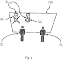
- FIG. 1 an exemplary situation is shown schematically in relation to a user B 1 and a user B 2 .
- the object is achieved by a laminated glass pane with a sensor arrangement according to claim 1.
- the laminated glass pane has a first glass layer and a second glass layer, connected by a combination film, the sensor arrangement being suitable for the approach of a finger to recognize.
- a hologram is arranged at the location of the sensor arrangement, which is optically perceptible to a viewer when illuminated, the hologram being arranged between the first glass layer and the second glass layer.
- the sensor arrangement has a capacitive sensor or an optical sensor.
- a capacitive sensor or an optical sensor.
- the hologram is applied to the combination film.
- the combination film By attaching it to the combination film, production can be simplified and, on the other hand, the hologram can be reliably protected from negative production influences as well as from damage caused by external influences.
- the combination film contains at least one substance selected from the group comprising polybutylene terephthalate (PBT), polycarbonate (PC), polyethylene terephthalate (PET) and polyethylene naphthalate (PEN), Polyvinyl chloride (PVC), polyvinyl fluoride (PVF), polyvinyl butyral (PVB), ethylene vinyl acetate (EVA), polyacrylate (PA), polymethyl methacrylate (PMMA), polyurethane (PUR), and / or mixtures and copolymers thereof.
- PBT polybutylene terephthalate
- PC polycarbonate
- PET polyethylene terephthalate
- PEN polyethylene naphthalate
- PVC Polyvinyl chloride
- PVF polyvinyl fluoride
- PVB polyvinyl butyral
- EVA ethylene vinyl acetate
- PA polyacrylate
- PMMA polymethyl methacrylate
- PUR polyurethane
- At least parts of the sensor arrangement are applied or introduced as wires on or in the combination film.
- the sensor arrangement has a flat, transparent, electrically conductive layer or a plurality of flat, transparent, electrically conductive layers, which are delimited by insulating dividing lines.
- the sensor arrangement and the hologram are arranged on a common section of the combination film or on a carrier within the laminated glass pane. With the joint provision on a common section, the production costs can be reduced.
- the hologram is designed in such a way that a representation of the hologram appears with illumination that is reflective in relation to the viewer.
- the appearance / disappearance of a hologram can be controlled through targeted lighting, so that, for example, only active sensor arrangements can be recognized as such, while inactive sensor arrangements remain hidden.
- different lighting e.g. different angles / different light, to generate the representation of different holograms in relation to the viewer.
- the hologram is designed in such a way that a representation of the hologram appears with illumination that is transmissive with respect to the viewer.
- the appearance / disappearance of a hologram can be controlled by external lighting, so that e.g. only certain sensor arrangements can be recognized as such, while inactive sensor arrangements remain hidden.
- a laminated glass pane arrangement according to the invention has a laminated glass pane and an illumination source which illuminates the hologram in a controllable manner so that it appears to the user.
- the laminated glass pane according to the invention can be used in vehicles or buildings or as an information display. That is, the range of applications is very wide, so that the laminated glass pane according to the invention can be produced inexpensively.
- the laminated glass pane according to the invention can be produced in a simple, cost-effective process that includes obtaining a hologram which includes the introduction of the hologram onto a combination film of the laminated glass pane, the introduction step being selected from lamination or gluing on the combination film, and which has the finishing of the laminated glass pane.
- the hologram is at least partially transparent.
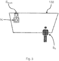
- FIG. 13 is an exemplary situation according to embodiments of the invention schematically in relation to a user B 1 and FIG Figure 3 shown in relation to another person B 2 .
- the laminated glass pane 100 has a sensor arrangement S touch or several sensor arrangements S touch , the laminated glass pane 100 having a first glass layer GS 1 and a second glass layer GS 2 , connected by at least one combination film F or a plurality of combination films F 1 , F 2 .
- the sensor arrangement (s) S touch is / are suitable for detecting the approach of a finger.
- the sensor area itself is identified by the fact that a hologram H is arranged at the location of the sensor arrangement, which is optically perceptible to a viewer B 1 when illuminated, the hologram H being between the first glass layer GS 1 and the second glass layer GS 2 is arranged.
- a sensor arrangement S touch is shown, which is located on the upper edge of a laminated glass pane 100. So that this sensor arrangement S touch can be recognized, a hologram H is provided in relation to the sensor arrangement S touch.
- the hologram H can appear to the user B 1 in a manner similar to the markings M 1 and M 2 .
- the hologram H is designed in such a way that it is partially transparent or even invisible to person B 2 who is not within range of the sensor arrangement S touch and cannot operate the sensor arrangement S touch. That is to say, the hologram H does not restrict the field of view of the person B 2.
- the sensor arrangement S touch can, for example, only be visible to the driver B1, for example to switch certain vehicle elements, while the passenger B2 cannot see the corresponding markings in the form of the hologram H.
- a sensor surface S touch is suitably attached within reach of the passenger B2 - e.g. to control an air conditioning / window / multimedia system - it can be advantageous that it is only visible to the passenger B 2 , while it is partially visible to the driver B 1. remains transparent or even invisible and does not restrict its field of vision.
- hologram H it is possible to provide position-selective markings, e.g. to identify sensor arrangements. This makes use of the fact that a user of a sensor arrangement is located in a certain angular range relative to the laminated glass pane 100, while another observer who is outside the range of the sensor arrangement assumes a different angle relative to the sensor range.
- the laminated glass pane 100 according to the invention is not restricted to a specific sensor technology. Rather, the sensor arrangement S touch can be used together with the most varied of sensor technologies.
- the sensor arrangement has a capacitive sensor or an optical sensor.
- the sensor arrangement (s) S touch is suitable for detecting the approach of a finger.
- the approximation can, for example, in In the case of a capacitive sensor, this can be detected by changing charges on a capacitor.
- detection is possible, for example, on the basis of a shadow cast by means of a light-sensitive resistor or a photoelectric cell, or by means of a camera outside the laminated glass pane 100, which observes the sensor arrangement.
- a shadow cast by means of a light-sensitive resistor or a photoelectric cell
- a camera or by means of a camera outside the laminated glass pane 100, which observes the sensor arrangement.
- not only the approach but also the direct placing of a finger on the sensor area can be recognized.
- the hologram H is on the combination film F; F 1 , F 2 applied.
- FIG. 14 is an exemplary section through a laminated glass pane 100 along the line AA ′ in FIG Figure 2 shown.
- a glass panel 1 and a GS GS glass panel 2 by way of example two combined films F 1 and f 2.
- the hologram at a suitable location can now, for example, on one of the films F 1 or F 2 may be applied, or a carrier T is introduced into a section of the combination film F 1, F 2, or - as shown - between the combination of film F 1, F 2 introduced.
- the cut is in Figure 4 to be understood only as an example and further layers can be provided between the glass pane GS 1 and a glass pane GS 2 .
- the glass pane GS 1 and / or the glass pane GS 2 preferably contain glass, particularly preferably flat glass, float glass, quartz glass, borosilicate glass, soda-lime glass, or clear plastics, preferably rigid clear plastics, in particular polyethylene, polypropylene, polycarbonate , Polymethyl methacrylate, polystyrene, polyamide, polyester, polyvinyl chloride and / or mixtures thereof.
- the glass pane GS 1 and the glass pane GS 2 are transparent, in particular for the use of the laminated glass pane 100 as a windshield or rear window of a vehicle or other uses in which a high light transmission is desired.
- transparent is understood to be a laminated glass pane 100 which has a transmission in the visible spectral range of greater than 70%.
- laminated glass panes 100 that are not relevant to traffic The driver's field of vision, for example for roof windows, but the transmission can also be much smaller, for example greater than 5%.
- the thickness of the glass pane GS 1 and / or the glass pane GS 2 can vary widely and thus be perfectly adapted to the requirements of the individual case. Standard thicknesses from 1.0 mm to 25 mm, preferably from 1.4 mm to 2.5 mm for vehicle glass and preferably from 4 mm to 25 mm for furniture, appliances and buildings, in particular for electric radiators, are preferably used.
- the size of the laminated glass pane 100 can vary widely and depends on the size of the use according to the invention.
- the substrate and, if appropriate, the cover pane have areas of 200 cm 2 to 20 m 2 , which are customary in vehicle construction and the architectural field, for example.
- the laminated glass pane 100 can have any three-dimensional shape.
- the three-dimensional shape preferably has no shadow zone, so that it can be coated, for example, by cathode sputtering.
- the substrates are preferably planar or slightly or strongly curved in one direction or in several directions of space.
- planar glass panes GS 1 and GS 2 are used.
- the glass pane GS 1 and / or GS 2 can be colorless or colored.
- the glass pane GS 1 and / or the glass pane GS 2 preferably have a relative permittivity ⁇ r, 1/4 of 2 to 8 and particularly preferably of 6 to 8. With such relative permittivities, it was possible to achieve a particularly good differentiation between a contact of the contact surface via the outside surface of the substrate and the outside surface of the cover disk.
- the combination film F; F 1 , F 2 at least one substance selected from the group comprising polybutylene terephthalate (PBT), polycarbonate (PC), polyethylene terephthalate (PET) and polyethylene naphthalate (PEN), polyvinyl chloride (PVC), polyvinyl fluoride (PVF), polyvinyl butyral (PVB), ethylene vinyl acetate ( EVA), polypropylene (PP), polyvinyl chloride (PVC), polyacrylate (PA), polymethyl methacrylate (PMMA), polyurethane (PUR), polyacetate resin, casting resins, acrylates, fluorinated ethylene-propylenes, polyvinyl fluoride and / or ethylene-tetrafluoroethylene and / or mixtures and copolymers thereof.
- the combination film F; F 1 , F 2 is transparent.
- the intermediate layer between the first glass pane GS 1 and the second glass pane GS 2 can be made up of one or more combination films F; F 1 , F 2 are formed, the thickness of a combination film F; F 1 , F 2 preferably from Is 0.025mm to 1mm, typically 0.38mm or 0.76mm.
- the intermediate layers are preferably thermoplastic and, after lamination , can glue the glass pane GS 1 , the glass pane GS 2 and any further intermediate layers to one another.
- the intermediate layer preferably has a relative permittivity of 2 to 4 and particularly preferably from 2.1 to 2.9. With such relative permittivities, it was possible to achieve a particularly good differentiation between a contact between the contact surface via the outside surface of the glass pane GS 2 and the outside surface of the glass pane GS 1 .
- the carrier T is preferably a transparent film.
- the carrier T preferably contains or consists of a polyethylene terephthalate (PET) film.
- PET polyethylene terephthalate
- the thickness of the carrier T is preferably from 0.025 mm to 0.1 mm.
- the carrier preferably has a relative permittivity of 2 to 4 and particularly preferably of 2.7 to 3.3.
- parts of the sensor arrangement S touch as wires on or in the combination film F; F 1 , F 2 or on the carrier T are applied or introduced.
- Electrically conductive layers L according to the invention are composed, for example, of DE 20 2008 017 611 U1 , EP 0 847 965 B1 or WO2012 / 052315 A1 known. They typically contain one or more, for example two, three or four, electrically conductive, functional layers.
- the functional layers preferably contain at least one metal, for example silver, gold, copper, nickel and / or chromium, or a metal alloy.
- the functional layers particularly preferably contain at least 90% by weight of the metal, in particular at least 99.9% by weight of the metal.
- the functional layers can be made from consist of the metal or metal alloy.
- the functional layers particularly preferably contain silver or an alloy containing silver. Such functional layers have a particularly advantageous electrical conductivity with simultaneous high transmission in the visible spectral range.
- the thickness of a functional layer is preferably from 5 nm to 50 nm, particularly preferably from 8 nm to 25 nm. In this range for the thickness of the functional layer, an advantageously high transmission in the visible spectral range and a particularly advantageous electrical conductivity are achieved.
- At least one dielectric layer is typically arranged between two adjacent functional layers.
- a further dielectric layer is preferably arranged below the first and / or above the last functional layer.
- a dielectric layer contains at least one single layer made of a dielectric material, for example containing a nitride such as silicon nitride or an oxide such as aluminum oxide.
- the dielectric layer can also comprise a plurality of individual layers, for example individual layers made of a dielectric material, smoothing layers, adaptation layers, blocker layers and / or antireflection layers.
- the thickness of a dielectric layer is, for example, from 10 nm to 200 nm.
- This layer structure is generally obtained through a sequence of deposition processes, which is carried out using a vacuum process such as magnetic field-assisted cathode sputtering.
- Such electrically conductive layers L preferably contain indium tin oxide (ITO), fluorine-doped tin oxide (SnO 2 : F) or aluminum-doped zinc oxide (ZnO: Al).
- ITO indium tin oxide
- SnO 2 : F fluorine-doped tin oxide
- ZnO aluminum-doped zinc oxide
- the electrically conductive layer L can in principle be any coating that can be electrically contacted. If the laminated glass pane 100 according to the invention is intended to enable transparency, as is the case, for example, with panes in the window area, the electrically conductive layer L is preferably transparent. In an advantageous embodiment, the electrically conductive layer L is a layer or a layer structure of several individual layers with a total thickness of less than or equal to 2 ⁇ m, particularly preferably less than or equal to 1 ⁇ m.
- the structure and coordination of sensor electronics is coordinated such that when the outside pane surface IV of the glass pane GS 1 is touched, a switching signal is triggered above the contact area 11 of the capacitive switching area outside pane surface I of the glass pane GS 2 above the capacitive switching range no switching signal is triggered.
- the thicknesses and the materials of the composite pane 100 according to the invention are selected according to the invention in such a way that the area capacitance layer c I between the contact area 11 and the outside surface IV of the glass pane GS 1 is greater than the area capacity layer c A between the contact area 11 and the outside surface I. the glass pane GS 2 is.
- the laminated glass pane can also have a low-E coating on the inside surface IV of the laminated glass pane 100, at least one capacitive switching area being electrically separated from the low-E coating by at least one coating-free dividing line U.
- the outer surface of the laminated glass pane 100 here means the surface of the pane that faces outwards, that is to say away from the (vehicle) interior.
- Inner surface accordingly means the surface of the laminated glass pane 100 which faces the (vehicle) interior.
- This low-E coating contains at least one functional layer and optionally one or more adhesive layers, barrier layers and / or anti-reflective layers.
- the low-E coating is preferably a layer system of at least one in each case Adhesive layer, a functional layer, a barrier layer, an anti-reflective layer and a further barrier layer.
- Particularly suitable low-E coatings contain a functional layer of at least one electrically conductive oxide (TCO), preferably indium tin oxide (ITO ), fluorine-doped tin oxide (SnO 2 : F), antimony-doped tin oxide (SnO 2 : Sb), aluminum-doped Zinc oxide (ZnO: AI) and / or gallium-doped zinc oxide (ZnO: Ga).
- TCO electrically conductive oxide
- ITO indium tin oxide
- F fluorine-doped tin oxide
- SnO 2 : F fluorine-doped tin oxide
- SnO 2 antimony-doped tin oxide
- ZnO aluminum-doped Zinc oxide
- ZnO: Ga gallium-doped zinc oxide
- Particularly advantageous low-E coatings have an interior emissivity of the laminated glass pane 100 according to the invention of less than or equal to 60%, preferably less than or equal to 45%, particularly preferably less than or equal to 30% and in particular less than or equal to 20%.
- Emissivity on the inside is the measure that indicates how much heat radiation the pane emits in the installed position compared to an ideal heat radiator (a black body) in an interior, for example a building or a vehicle.
- Emissivity is understood to mean the normal total emissivity at 283 K according to the EN 12898 standard.
- the sheet resistance of such an exemplary Low-E coating is from 10 ohms / square to 200 ohms / square and preferably from 10 ohms / square to 100 ohms / square, particularly preferably from 15 ohms / square to 50 ohms / square and especially from 20 ohms / square to 35 ohms / square.
- the absorption of the Low-E coating in the visible spectral range is preferably from about 1% to about 15%, particularly preferably from about 1% to about 7%.
- the absorption of the coating can be determined by measuring the absorption of a coated pane and subtracting the absorption of the uncoated pane.
- the pane preferably has a color value a * from -15 to +5 and a color value b * from -15 to +5, viewed from the side provided with the low-E coating according to the invention.
- the details a * and b * relate to the color coordinates according to the colorimetric model (L * a * b * color space).
- An advantageous low-E coating has a low absorption and a low reflection and therefore a high transmission in the visible spectral range.
- the Low-E coating can therefore also be used on windows where a significant reduction in transmission is not desired, for example window panes in buildings, or is prohibited by law, for example windshields or front side windows in motor vehicles.
- Another advantageous transparent electrically conductive layer L can also have a sheet resistance of 0.4 ohm / square to 200 ohm / square.
- the electrically conductive layer according to the invention has a sheet resistance of 0.5 ohm / square to 20 ohm / square.
- Coatings with such surface resistances are suitable, among other things, for heating vehicle windows with typical on-board voltages of 12 V to 48 volts or in electric vehicles with typical on-board voltages of up to 500 V.
- the sensor arrangement S touch has at least one flat, transparent, electrically conductive layer L which is delimited by insulating dividing lines U.
- a corresponding capacitive sensor is formed there on a carrier T which has an electrically conductive coating L.
- This has two comparatively large areas A 1 and A 2 , which are arranged at the upper end shown.
- the surfaces are connected to exemplary connections AN 1 and AN 2 via connections V 1 and V 2 .
- the connections AN 1 and AN 1 are connected to exemplary sensor evaluation electronics via two flat ribbon connections K 1 and K 2 attached by means of solder LOT.
- Other forms of sensor construction, in particular wireless connected sensors, are hereby explicitly not excluded.
- the plate A 2 and the connections V 2 and the connection A 2 are formed from the electrically conductive layer L by means of the dividing line U.
- the plate A 1 and the connections V 1 and the connection A 1 are formed from the electrically conductive layer L by means of a further dividing line U.
- These dividing line (s) U can be structured, for example, by means of a laser (ablation).
- a holographic structure (structure having different thickness profiles and / or refractive index profiles) is produced by (hot) embossing a, for example, embossable lacquer on an exemplary PET film, for example 19 ⁇ m-50 ⁇ m thick.
- this PET film can also serve as a carrier T for electrical layers L of the sensor arrangement S touch .
- such a PET film has a tensile strength of approximately 24 kgf / mm 2 , the elongation at break being 120% - 150% and the heat shrinkage at 150 ° / 30min being 1% and less.
- such PET films have a haze of 1% with a transmission of 90%.
- Such a carrier T can, for example, be coated with a highly reflective metallization M, it also being possible for further layers to be provided for application.
- the metallization M can e.g. be produced on the basis of ZnS, which has a refractive index of 2.3 - 2.4 with a 35% reflectivity.
- a coating C 1 can be located on the side facing away from the viewer, as required. This coating C 1 can, for example, allow printing with non-holographic elements.
- a separating layer RC can be located on the side facing the viewer as required. Furthermore, a second coating C 2 can optionally be provided, which, for example, carries the embossable lacquer PL.
- the hologram H is designed in such a way that it is illuminated by ambient light and also by targeted lighting, be it by means of an illumination that is integrated into the pane / sensor arrangement Illumination by means of suitable (organic) light-emitting diodes (p) LEDs, be it by an illumination source arranged outside the laminated glass pane 100, is illuminated in such a way that the user of the sensor arrangement S touch can localize the sensor arrangement.
- suitable (organic) light-emitting diodes (p) LEDs be it by an illumination source arranged outside the laminated glass pane 100, is illuminated in such a way that the user of the sensor arrangement S touch can localize the sensor arrangement.
- the hologram H can be designed, for example, in such a way that a representation of the hologram H appears with illumination that is reflective in relation to the viewer.
- a hologram can be controlled through targeted lighting so that, for example, only active sensor arrangements can be recognized as such, while inactive sensor arrangements remain hidden.
- different illuminations e.g. different angles / different light in relation to the laminated glass pane 100 or an embossing of the hologram H, to produce the representation of different holograms in relation to the viewer.
- a representation of the hologram H appears in the case of illumination that is transmissive with respect to the viewer.
- the hologram H can also have several superimposed representations which, depending on the lighting (e.g. the angle of the lighting), are displayed in relation to the user.
- One embodiment of the invention shows a laminated glass pane arrangement which has a laminated glass pane 100 and an illumination source, the illumination source controllably illuminating the hologram H so that it appears to the user.
- the illumination source preferably has an LED or OLED.
- the particular advantage lies in the small dimensions and the low power consumption.
- the wavelength range emitted by the illumination source can be freely selected in the range of visible light, for example according to practical and / or aesthetic aspects.
- the light irradiation means can comprise optical elements, in particular for directing the light, preferably a reflector and / or an optical waveguide, for example a glass fiber or a polymer optical fiber.
- the illumination source can be at any point (relative to) the glass pane GS 1 or the glass pane GS 2 be arranged, in particular on the side edge of the glass pane GS 1 or the glass pane GS 2 or in a small recess in the middle of the glass pane GS 1 or the glass pane GS 2 .
- the light deflecting means preferably has particles, point grids, stickers, deposits, notches, incisions, line grids, prints and / or screen prints and is suitable for decoupling the light transported in the glass pane GS 1 or the glass pane GS 2 from the same.
- the light deflection means can be arranged at any desired position on the plane of the glass pane GS 1 or the glass pane GS 2 . It is particularly advantageous if the light deflection means is arranged in the area or in the immediate vicinity of the contact area and thus enables the otherwise barely visible contact area of the sensor arrangement S touch to be found quickly. This is particularly advantageous at night or in the dark.
- light can be guided to the contact area of the sensor arrangement S touch through a light guide arranged on the glass pane GS 1 or the glass pane GS 2 , or an intermediate layer (e.g. the combination film F, F 1 , F 2) and mark it.
- a light guide arranged on the glass pane GS 1 or the glass pane GS 2 , or an intermediate layer (e.g. the combination film F, F 1 , F 2) and mark it.
- the light irradiation means together with the light deflection means can visualize information on the pane, for example reproduce the switching state of the capacitive switching area or indicate whether, for example, an electrical function is switched on or off.
- the laminated glass pane 100 according to the invention can be used in vehicles or buildings or as an information display.
- the range of applications is very wide, so that the laminated glass panes 100 according to the invention can be produced inexpensively.
- a hologram H is first obtained.
- This hologram H can be part of the sensor arrangement S touch or it can be an independent hologram H (for example on a carrier T).
- the hologram H obtained is introduced into a preliminary product of the laminated glass pane 100, the introduction step being selected from lamination, gluing, Hang up. After the introduction and any further intermediate steps with regard to the sensor arrangement, the laminated glass pane 100 is completed.
- the sensor arrangement S touch is represented in a position-sensitive manner.
- the invention makes it its own that a user B 1 is at a typical distance (approximately 60 cm) in front of the laminated glass pane 100 so that he is able to operate the sensor of the sensor arrangement S touch.
- the hologram H is designed in such a way that, given the appropriate incidence of light, it can be seen well essentially at this distance and when viewed from a certain angular range, while it becomes partially transparent or even completely invisible for "viewers" from other distances and / or angular ranges.
- the ambient light is generally sufficient during the day to make a hologram H visible to the viewer B 1 , it may be necessary to provide external lighting in the dark so that the hologram H is visible again.
- This source of illumination can in turn be suitably placed. For example, this can be arranged in a vehicle on the roof lining, the dashboard or an A-pillar, in a rear-view mirror holder, etc., so that the light from the illumination source does not disturb the viewer B 1.
- holograms H Another advantage of holograms H is that these holograms cannot be seen on the side facing away from the user.
- a sensor arrangement S touch and the hologram H are arranged for this purpose in such a way that they can be seen on the inside of a vehicle.
- the hologram H cannot be seen on the outside. The localization of the sensor arrangement S touch cannot therefore be found, or cannot be found easily, so that incorrect operation from the outside is made more difficult.
Landscapes
- Engineering & Computer Science (AREA)
- Theoretical Computer Science (AREA)
- Physics & Mathematics (AREA)
- General Physics & Mathematics (AREA)
- General Engineering & Computer Science (AREA)
- Business, Economics & Management (AREA)
- Marketing (AREA)
- Accounting & Taxation (AREA)
- Human Computer Interaction (AREA)
- Civil Engineering (AREA)
- Structural Engineering (AREA)
- Mechanical Engineering (AREA)
- Joining Of Glass To Other Materials (AREA)
- Laminated Bodies (AREA)
- Holo Graphy (AREA)
Description
- Die Erfindung betrifft eine Verbundglas-Scheibe mit einer Sensoranordnung und ein Verfahren zur Herstellung einer Verbundglas-Scheibe mit einer Sensoranordnung.
- Es ist bekannt, dass Schaltbereiche durch eine Flächenelektrode oder durch eine Anordnung von zwei gekoppelten Elektroden ausgebildet werden können, beispielsweise als kapazitive Schaltbereiche. Nähert sich ein Objekt, z.B. ein Finger, dem Schaltbereich an, so ändert sich die Kapazität der Flächenelektrode gegen Erde oder die Kapazität des von den zwei gekoppelten Elektroden gebildeten Kondensators. Derartige Schaltbereiche sind beispielsweise aus
US 2010/179725 A1 ,US 6 654 070 B1 ,WO 2013/091961 A1 undUS 2006/275599 A1 bekannt. - Die Kapazitätsänderung wird über eine Schaltungsanordnung oder Sensorelektronik gemessen und bei Überschreiten eines Schwellwertes wird ein Schaltsignal ausgelöst. Schaltungsanordnungen für kapazitive Schalter sind beispielsweise aus
DE 20 2006 006 192 U1 ,EP 0 899 882 A1 ,US 6,452,514 B1 undEP 1 515 211 A1 bekannt. - Aus
WO 2013 / 053 611 A1 ist eine elektrochrome Isolierverglasung mit Sensorfläche bekannt. - Weiterhin ist aus
DE 35 32 120 A1 eine Windschutzscheibe mit einer reflektierenden - Einrichtung zur Einspiegelung von optischen Informations- bzw. Warn-Signalen in das Gesichtsfeld des Fahrers mittels eines Reflexionshologrammes mit Spiegeleigenschaften bekannt.
- Insbesondere bei durchsichtigen oder kleinflächigen Sensorflächen kann es jedoch problematisch sein, die Sensorfläche als solche durch einen Benutzer erkennen zu können.
- In
Figur 1 ist eine beispielhafte Situation schematisch in Bezug auf einen Benutzer B1 und einen Benutzer B2 dargestellt. - Dargestellt sind schematisch 2 Sensoranordnungen Stouch, welche sich am oberen Rand einer Verbundglasscheibe 100 befinden. Damit diese erkennbar werden, ist in Bezug auf die linke Sensoranordnung eine erste Markierung M1 aufgebracht, die beispielsweise den sensitiven Bereich mittels Pfeilen signalisiert, und in Bezug auf die rechte Sensoranordnung ist eine zweite Markierung M2 aufgebracht, die beispielsweise den Bereich mittels eines Kreises signalisiert. Dabei ist zu bemerken, dass die dauerhafte Anbringung von Markierungen sich als störend darstellen kann, insbesondere jedoch, wenn eine Sensoranordnung nicht von einer Person, die nicht in Reichweite der Sensoranordnung ist, bedient werden kann. Beispielsweise ist die linke Sensoranordnung durch Person B2 nicht erreichbar, sodass die Markierung M1 das Sichtfeld der Person B2 einschränkt.Solche Situationen sind insbesondere bei Fahrzeugscheiben nachteilig, da hier bestimmte Anforderungen an das Sichtfeld gestellt werden.
- Es wäre daher wünschenswert, Verbundglas-Scheiben mit Sensoranordnungen bereitstellen zu können, die Sensoranordnungen positions-selektiv wahrnehmbar machen.
- Die Aufgabe wird gelöst durch eine Verbundglas-Scheibe mit einer Sensoranordnung nach Patentanspruch 1. Die Verbundglas-Scheibe weist eine erste Glas-Schicht und eine zweite Glas-Schicht, verbunden durch eine Kombinationsfolie, auf, wobei die Sensoranordnung geeignet ist, die Annäherung eines Fingers zu erkennen. Dabei ist am Ort der Sensoranordnung ein Hologramm angeordnet, welches bei Beleuchtung für einen Betrachter optisch wahrnehmbar wird, wobei das Hologramm zwischen der ersten Glas-Schicht und der zweiten Glas-Schicht angeordnet ist.
- Mit der erfindungsgemäßen Anordnung wird erreicht, dass eine Sensoranordnung positions-selektiv wahrnehmbar wird, sodass eine Person, die auch die Sensoranordnung bedienen kann, die Position der Sensoranordnung erkennen kann, während für andere Personen, die die Sensoranordnung nicht bedienen können, Störungen des Sichtfeldes vermindert werden.
- In einer Ausgestaltung der Erfindung weist die Sensoranordnung einen kapazitiven Sensor oder einen optischen Sensor auf.D.h. mittels der Erfindung können unterschiedliche Arten von Sensoren kenntlich gemacht werden, wodurch ein hohe Einsatzbandbreite ermöglich wird.
- In einer weiteren Ausgestaltung der Erfindung ist das Hologramm auf der Kombinationsfolie aufgebracht. Mit der Anbringung auf der Kombinationsfolie kann die Produktion vereinfacht werden und zum anderen das Hologramm zuverlässig vor negativen Produktionseinflüssen als auch vor Beschädigungen durch äußere Einwirkungen geschützt werden.
- Gemäß einer weiteren Ausgestaltung der Erfindung enthält die Kombinationsfolie zumindest einen Stoff ausgewählt aus der Gruppe aufweisend Polybutylenterephthalat (PBT), Polycarbonat (PC), Polyethylenterephthalat (PET) und Polyethylennaphthalat (PEN), Polyvinylchlorid (PVC), Polyvinylfluoride (PVF), Polyvinylbutyral (PVB), Ethylenvinylacetat (EVA), Polyacrylat (PA), Polymethylmethacrylat (PMMA), Polyurethan (PUR), und/oder Gemische und Copolymere davon.D.h. die Erfindung erlaubt die vielseitige Anpassung an unterschiedliche optische und mechanische Gegebenheiten.
- Gemäß einer weiteren Ausgestaltung der Erfindung sind zumindest Teile der Sensoranordnung als Drähte auf oder in der Kombinationsfolie aufgebracht bzw. eingebracht. Mit der Aufbringung bzw. Einbringung von Teilen der Sensoranordnung auf der Kombinationsfolie wird erreicht, dass die Produktionskosten reduziert werden können und die Scheibendicke gering gehalten werden kann.
- In einer weiteren Ausgestaltung der Erfindung weist die Sensoranordnung eine flächige, transparente, elektrisch leitfähige Schicht oder mehrere flächige, transparente, elektrisch leitfähige Schichten auf, welche durch isolierende Trennlinien begrenzt sind.
- Gemäß einer weiteren Ausgestaltung der Erfindung sind die Sensoranordnung und das Hologramm auf einem gemeinsamen Abschnitt der Kombinationsfolie oder einem Träger innerhalb der Verbundglasscheibe angeordnet. Mit der gemeinsamen Bereitstellung auf einen gemeinsamen Abschnitt können die Produktionskosten reduziert werden.
- In einer weiteren Ausgestaltung ist das Hologramm so gestaltet, dass eine Darstellung des Hologramms bei einer in Bezug auf den Betrachter reflektiven Beleuchtung erscheint.D.h. durch gezielte Beleuchtung kann das Erscheinen / Verschwinden eines Hologramms gesteuert werden, sodass z.B. nur aktive Sensoranordnungen als solche erkennbar sind, während inaktive Sensoranordnungen verborgen bleiben. Zudem ist es möglich über unterschiedliche Beleuchtungen, z.B. unterschiedliche Winkel / unterschiedliches Licht, die Darstellung unterschiedlicher Hologramme in Bezug auf den Betrachter zu erzeugen.
- Erfindungsgemäß ist das Hologramm so gestaltet, dass eine Darstellung des Hologramms bei einer in Bezug auf den Betrachter transmissiven Beleuchtung erscheint.D.h. durch äußere Beleuchtung kann das Erscheinen / Verschwinden eines Hologramms gesteuert werden, sodass z.B. nur bestimmte Sensoranordnungen als solche erkennbar sind, während inaktive Sensoranordnungen verborgen bleiben.
- Gemäß einer weiteren Ausgestaltung der Erfindung weist eine erfindungsgemäße Verbundglasscheiben-Anordnung eine Verbundglasscheibe und eine Beleuchtungsquelle auf, welche kontrollierbar das Hologramm beleuchtet, sodass es dem Benutzer erscheint. Gemäß einer weiteren Ausgestaltung der Erfindung kann die erfindungsgemäße Verbundglas-Scheibe in Fahrzeugen oder Gebäuden oder als Informationsdisplay verwendet werden.D.h. die Anwendungsbreite ist sehr hoch, sodass die erfindungsgemäße Verbundglas-Scheibe kostengünstig hergestellt werden kann.
- Gemäß einer weiteren Ausgestaltung der Erfindung kann die erfindungsgemäße Verbundglas-Scheibe in einem einfachen kostengünstigen Verfahren hergestellt werden, das das Erhalten eines Hologramms aufweist, das das Einbringen des Hologramms auf eine Kombinationsfolie der Verbundglasscheibe aufweist, wobei der Schritt des Einbringens ausgewählt ist aus Laminieren oder Kleben auf die Kombinationsfolie, und das das Fertigstellen der Verbundglasscheibe aufweist.
- Gemäß der Erfindung ist das Hologramm zumindest teil-transparent.
- Ausführungsformen der vorliegenden Erfindung werden in exemplarischer Weise mit Bezug auf die angehängten Zeichnungen beschrieben, welche zeigen:
-
Fig. 1 eine schematische Übersichtsdarstellung einer Verbundglas-Scheibe mit einer Sensoranordnung aus dem Stand der Technik, -
Fig. 2 eine schematische Übersichtsdarstellung einer erfindungsgemäßen Verbundglas-Scheibe mit einer Sensoranordnung in Bezug auf eine erste Benutzer-Position, -
Fig. 3 eine schematische Übersichtsdarstellung einer erfindungsgemäßen Verbundglas-Scheibe mit einer Sensoranordnung in Bezug auf eine zweite Benutzer-Position, -
Fig. 4 einen schematischen Querschnitt durch eine erfindungsgemäße Sensoranordnung, -
Fig. 5 eine schematische Übersichtsdarstellung einer erfindungsgemäßen Sensoranordnung, und -
Fig. 6 einen schematischen Querschnitt durch ein Hologramm. - In
Figur 2 ist eine beispielhafte Situation gemäß Ausführungsformen der Erfindung schematisch in Bezug auf einen Benutzer B1 und inFigur 3 in Bezug auf eine weitere Person B2 dargestellt. - Die erfindungsgemäße Verbundglas-Scheibe 100 weist eine Sensoranordnung Stouch oder mehrere Sensoranordnungen Stouch auf, wobei die Verbundglas-Scheibe 100 eine erste Glas-Schicht GS1 und eine zweite Glas-Schicht GS2, verbunden durch zumindest einer Kombinationsfolie F bzw. eine Vielzahl von Kombinationsfolien F1, F2, aufweist. Die Sensoranordnung(en) Stouch ist/sind geeignet, die Annäherung eines Fingers zu erkennen. Der Sensorbereich selbst ist dadurch kenntlich gemacht, dass am Ort der Sensoranordnung ein Hologramm H angeordnet ist, welches bei Beleuchtung für einen Betrachter B1 optisch wahrnehmbar wird, wobei das Hologramm H zwischen der ersten Glas-Schicht GS1 und der zweiten Glas-Schicht GS2 angeordnet ist.
- D.h. analog zur
Figur 1 ist inFigur 2 eine Sensoranordnung Stouch dargestellt, welche sich am oberen Rand einer Verbundglasscheibe 100 befindet. Damit diese Sensoranordnung Stouch erkennbar wird, ist in Bezug auf die Sensoranordnung Stouch ein Hologramm H vorgesehen. Das Hologramm H kann dem Benutzer B1 ähnlich wie die Markierungen M1 und M2 erscheinen. Hingegen ist das Hologramm H so gestaltet, dass es für Person B2, die nicht in Reichweite der Sensoranordnung Stouch ist und die Sensoranordnung Stouch nicht bedienen kann, teiltransparent oder sogar unsichtbar ist. D.h., das Hologramm H schränkt das Sichtfeld der Person B2 nicht ein. - Eine solche Situation ist insbesondere bei Fahrzeugscheiben von Vorteil, da hier bestimmte Anforderungen an das Sichtfeld gestellt werden. So kann z.B. die Sensoranordnung Stouch beispielsweise nur für den Fahrer B1 sichtbar sein, z.B. zum Schalten von bestimmten Fahrzeugelementen, während der Beifahrer B2 die entsprechenden Markierungen in Form des Hologramms H nicht sehen kann. Umgekehrt kann es aber auch bei geeigneter Anbringung einer Sensorfläche Stouch in Reichweite des Beifahrers B2 - z.B. zur Steuerung einer Klimatiersierung / Fenster / Multimediaanlage - vorteilhaft sein, dass diese nur dem Beifahrer B2 sichtbar ist, während sie für den Fahrer B1 teil-transparent oder sogar unsichtbar bleibt und so sein Sichtfeld nicht einschränkt.
- D.h. mittels des Hologramms H ist es möglich, positions-selektive Markierungen, z.B. zur Kenntlichmachung von Sensoranordnungen, bereitzustellen. Dabei wird ausgenutzt, dass sich ein Benutzer einer Sensoranordnung in einem bestimmten Winkelbereich relativ zur Verbundglas-Scheibe 100 befindet, während ein anderer Betrachter, der sich außerhalb der Reichweite der Sensoranordnung befindet, einen anderen Winkel relativ zum Sensorbereich einnimmt.
- Dabei ist die erfindungsgemäße Verbundglas-Scheibe 100 nicht auf eine bestimmte Sensortechnik festgelegt. Vielmehr kann die Sensoranordnung Stouch mit verschiedensten Sensortechniken zusammen verwendet werden. Beispielsweise weist die Sensoranordnung einen kapazitiven Sensor oder einen optischen Sensor auf. Die Sensoranordnung(en) Stouch ist geeignet, die Annäherung eines Fingers zu erkennen. Die Annäherung kann z.B. im Falle eines kapazitiven Sensors durch Änderung von Ladungen auf einem Kondensator erkannt werden. Im Falle eines optischen Sensors ist die Erkennung z.B. anhand eines Schattenwurfes mittels eines lichtempfindlichen Widerstandes oder einer photoelektrischen Zelle oder aber mittels einer Kamera außerhalb der Verbundglas-Scheibe 100 möglich, die die Sensoranordnung beobachtet. Natürlich kann nicht nur die Annäherung sondern auch das direkte Auflegen eines Fingers auf den Sensorbereich erkannt werden.
- In der nachfolgenden Beschreibung werden insbesondere kapazitive Sensoren zur Erkennung der Annäherung beschrieben werden. Die Erfindung ist jedoch hierauf nicht beschränkt.
- In einer Ausgestaltung der Erfindung ist das Hologramm H auf der Kombinationsfolie F; F1, F2 aufgebracht.
- In
Figur 4 ist ein beispielhafter Schnitt durch eine Verbundglas-Scheibe 100 entlang der Linie A-A' inFigur 2 gezeigt. - Dort befinden sich zwischen einer Glas-Scheibe GS1 und einer Glas-Scheibe GS2 beispielhaft zwei Kombinationsfolien F1 und F2. Hier kann nun beispielsweise auf eine der Folien F1 oder F2 das Hologramm an geeigneter Stelle aufgebracht sein, oder aber ein Träger T wird in einen Ausschnitt der Kombinationsfolie F1, F2 eingebracht oder - wie dargestellt - zwischen der Kombinationsfolie F1, F2 eingebracht. Dabei ist der Schnitt in
Figur 4 nur beispielhaft zu verstehen und es können weitere Schichten zwischen der Glas-Scheibe GS1 und einer Glas-Scheibe GS2 vorgesehen sein. - Die Glas-Scheibe GS1 und/oder die Glas-Scheibe GS2 enthalten bevorzugt Glas, besonders bevorzugt Flachglas, Floatglas, Quarzglas, Borosilikatglas, Kalk-Natron-Glas, oder klare Kunststoffe, vorzugsweise starre klare Kunststoffe, insbesondere Polyethylen, Polypropylen, Polycarbonat, Polymethylmethacrylat, Polystyrol, Polyamid, Polyester, Polyvinylchlorid und/oder Gemische davon.
- Die Glas-Scheibe GS1 und die Glas-Scheibe GS2 sind transparent, insbesondere für die Verwendung der Verbundglas-Scheibe 100 als Windschutzscheibe oder Rückscheibe eines Fahrzeugs oder anderen Verwendungen, bei denen eine hohe Lichttransmission erwünscht ist. Als transparent im Sinne der Erfindung wird eine Verbundglas-Scheibe 100 verstanden, die eine Transmission im sichtbaren Spektralbereich von größer als 70 % aufweist. Für Verbundglas-Scheiben 100, die nicht im verkehrsrelevanten Sichtfeld des Fahrers liegen, beispielsweise für Dachscheiben, kann die Transmission aber auch viel geringer sein, beispielsweise größer als 5 %.
- Die Dicke von Glas-Scheibe GS1 und/oder Glas-Scheibe GS2 kann breit variieren und so hervorragend den Erfordernissen des Einzelfalls angepasst werden. Vorzugsweise werden Standardstärken von 1,0 mm bis 25 mm, bevorzugt von 1,4 mm bis 2,5 mm für Fahrzeugglas und bevorzugt von 4 mm bis 25 mm für Möbel, Geräte und Gebäude, insbesondere für elektrische Heizkörper, verwendet. Die Größe der Verbundglas-Scheibe 100 kann breit variieren und richtet sich nach der Größe der erfindungsgemäßen Verwendung. Das Substrat und gegebenenfalls die Deckscheibe weisen beispielsweise im Fahrzeugbau und Architekturbereich übliche Flächen von 200 cm2 bis zu 20 m2 auf.
- Die Verbundglas-Scheibe 100 kann eine beliebige dreidimensionale Form aufweisen. Vorzugsweise hat die dreidimensionale Form keine Schattenzone, sodass sie beispielsweise durch Kathodenzerstäubung beschichtet werden kann. Bevorzugt sind die Substrate planar oder leicht oder stark in einer Richtung oder in mehreren Richtungen des Raumes gebogen. Insbesondere werden planare Glas-Scheiben GS1 und GS2 verwendet. Die Glas-Scheibe GS1 und/oder GS2 können farblos oder gefärbt sein.
- Die Glas-Scheibe GS1 und/oder die Glas-Scheibe GS2 weisen bevorzugt eine relative Permittivität εr,1/4 von 2 bis 8 und besonders bevorzugt von 6 bis 8 auf. Bei derartigen relativen Permittivitäten konnte eine besonders gute Unterscheidung zwischen einer Berührung der Berührungsfläche über die außenseitige Oberfläche des Substrats von gegenüber der außenseitigen Oberfläche der Deckscheibe erzielt werden.
- Besonders vorteilhaft ist es, wenn die Kombinationsfolie F; F1, F2 zumindest einen Stoff ausgewählt aus der Gruppe aufweisend Polybutylenterephthalat (PBT), Polycarbonat (PC), Polyethylenterephthalat (PET) und Polyethylennaphthalat (PEN), Polyvinylchlorid (PVC), Polyvinylfluoride (PVF), Polyvinylbutyral (PVB), Ethylenvinylacetat (EVA), Polypropylen (PP), Polyvinylchlorid (PVC), Polyacrylat (PA), Polymethylmethacrylat (PMMA), Polyurethan (PUR), Polyacetatharz, Gießharze, Acrylate, fluorinierte Ethylen-Propylene, Polyvinylfluorid und/oder Ethylen-Tetrafluorethylen und/oder Gemische und Copolymere davon enthält. Die Kombinationsfolie F; F1, F2 ist transparent.
- Die Zwischenschicht zwischen der ersten Glas-Scheibe GS1 und der zweiten Glas-Scheibe GS2 kann durch eine oder auch durch mehrere übereinander angeordnete Kombinationsfolien F; F1, F2 ausgebildet werden, wobei die Dicke einer Kombinationsfolie F; F1, F2 bevorzugt von 0,025 mm bis 1 mm beträgt, typischerweise 0,38 mm oder 0,76 mm. Die Zwischenschichten sind bevorzugt thermoplastisch und können nach der Lamination die Glas-Scheibe GS1, die Glas-Scheibe GS2 und eventuelle weitere Zwischenschichten miteinander verkleben. Die Zwischenschicht hat bevorzugt eine relative Permittivität von 2 bis 4 und besonders bevorzugt von 2,1 bis 2,9. Bei derartigen relativen Permittivitäten konnte eine besonders gute Unterscheidung zwischen einer Berührung der Berührungsfläche über die außenseitige Oberfläche der Glas-Scheibe GS2 von gegenüber der außenseitigen Oberfläche der Glas-Scheibe GS1 erzielt werden.
- Der Träger T ist bevorzugt eine transparente Folie. Der Träger T enthält bevorzugt eine Polyethylenterepthalat (PET)-Folie oder besteht daraus. Die Dicke des Trägers T beträgt bevorzugt von 0,025 mm bis 0,1 mm. Der Träger hat bevorzugt eine relative Permittivität von 2 bis 4 und besonders bevorzugt von 2,7 bis 3,3. Mit einem derartigen Träger T lassen sich besonders gute Verbundglas-Scheiben 100 herstellen, da derart dünne Träger T auch bei nur abschnittsweiser Anordnung gut und optisch unauffällig in der Verbundglas-Scheibe 100 integrierbar sind. Gleichzeit lassen sich gute und selektive Schaltsignale erzeugen.
- Weiterhin vorteilhaft ist es, wenn z.B. Teile der Sensoranordnung Stouch als Drähte auf oder in der Kombinationsfolie F; F1, F2 bzw. auf dem Träger T aufgebracht bzw. eingebracht sind.
- Dies wird nachfolgend am Beispiel eines kapazitiven Sensors in Bezug auf
Figur 4 und5 erläutert. - Beispielhaft kann auf dem Träger T eine elektrisch leitfähige Schicht L angeordnet sein. Die elektrisch leitfähige Schicht L enthält bevorzugt eine transparente, elektrisch leitfähige Beschichtung. Transparent bedeutet hier durchlässig für elektromagnetische Strahlung, vorzugsweise elektromagnetische Strahlung einer Wellenlänge von 300 nm bis 1.300 nm und insbesondere für sichtbares Licht.
- Erfindungsgemäße elektrisch leitfähige Schichten L sind beispielsweise aus
DE 20 2008 017 611 U1 ,EP 0 847 965 B1 oderWO2012/052315 A1 bekannt. Sie enthalten typischerweise eine oder mehrere, beispielsweise zwei, drei oder vier elektrisch leitfähige, funktionelle Schichten. Die funktionellen Schichten enthalten bevorzugt zumindest ein Metall, beispielsweise Silber, Gold, Kupfer, Nickel und/oder Chrom, oder eine Metalllegierung. Die funktionellen Schichten enthalten besonders bevorzugt mindestens 90 Gew. % des Metalls, insbesondere mindestens 99,9 Gew. % des Metalls. Die funktionellen Schichten können aus dem Metall oder der Metalllegierung bestehen. Die funktionellen Schichten enthalten besonders bevorzugt Silber oder eine silberhaltige Legierung. Solche funktionelle Schichten weisen eine besonders vorteilhafte elektrische Leitfähigkeit bei gleichzeitiger hoher Transmission im sichtbaren Spektralbereich auf. Die Dicke einer funktionellen Schicht beträgt bevorzugt von 5 nm bis 50 nm, besonders bevorzugt von 8 nm bis 25 nm. In diesem Bereich für die Dicke der funktionellen Schicht wird eine vorteilhaft hohe Transmission im sichtbaren Spektralbereich und eine besonders vorteilhafte elektrische Leitfähigkeit erreicht. - Typischerweise ist jeweils zwischen zwei benachbarten funktionellen Schichten zumindest eine dielektrische Schicht angeordnet. Bevorzugt ist unterhalb der ersten und/oder oberhalb der letzten funktionellen Schicht eine weitere dielektrische Schicht angeordnet. Eine dielektrische Schicht enthält zumindest eine Einzelschicht aus einem dielektrischen Material, beispielsweise enthaltend ein Nitrid wie Siliziumnitrid oder ein Oxid wie Aluminiumoxid. Die dielektrische Schicht kann aber auch mehrere Einzelschichten umfassen, beispielsweise Einzelschichten aus einem dielektrischen Material, Glättungsschichten, Anpassungsschichten, Blockerschichten und / oder Antireflexionsschichten. Die Dicke einer dielektrischen Schicht beträgt beispielsweise von 10 nm bis 200 nm.
- Dieser Schichtaufbau wird im Allgemeinen durch eine Folge von Abscheidevorgängen erhalten, die durch ein Vakuumverfahren wie die magnetfeldgestützte Kathodenzerstäubung durchgeführt wird.
- Weitere geeignete elektrisch leitfähige Schichten L enthalten bevorzugt Indium-Zinnoxid (ITO), fluordotiertes Zinnoxid (SnO2:F) oder aluminiumdotiertes Zinkoxid (ZnO:Al).
- Die elektrisch leitfähige Schicht L kann prinzipiell jede Beschichtung sein, die elektrisch kontaktiert werden kann. Soll die erfindungsgemäße Verbundglas-Scheibe 100 die Durchsicht ermöglichen, wie es beispielsweise bei Scheiben im Fensterbereich der Fall ist, so ist die elektrisch leitfähige Schicht L bevorzugt transparent. In einer vorteilhaften Ausgestaltung ist die elektrisch leitfähige Schicht L eine Schicht oder ein Schichtaufbau mehrerer Einzelschichten mit einer Gesamtdicke von kleiner oder gleich 2 µm, besonders bevorzugt kleiner oder gleich 1 µm.
- Im dargestellten Ausgestaltungsbeispiel ist der Aufbau und die Abstimmung einer Sensorelektronik derart abgestimmt, dass bei Berührung der außenseitigen Scheibenoberfläche IV der Glas-Scheibe GS1 über dem Berührungsbereich 11 des kapazitiven Schaltbereichs ein Schaltsignal ausgelöst wird, wobei bei Berührung der außenseitigen Scheibenoberfläche I der Glas-Scheibe GS2 über dem kapazitiven Schaltbereich kein Schaltsignal ausgelöst wird. Dazu werden die Dicken und die Materialien der erfindungsgemäßen Verbundscheibe 100 erfindungsgemäß so gewählt, dass der Flächenkapazitätsbelag cI zwischen dem Berührungsbereich 11 und der außenseitigen Oberfläche IV der Glas-Scheibe GS1 größer als der Flächenkapazitätsbelag cA zwischen dem Berührungsbereich 11 und der außenseitigen Oberfläche I der Glas-Scheibe GS2 ist.
- Der Flächenkapazitätsbelag cI beziehungsweise cA ist im Rahmen der vorliegenden Erfindung definiert als die Kapazität eines Plattenkondensators desjenigen Bereichs der Verbundglas-Scheibe 100, der sich durch orthogonale Projektion des Berührungsbereichs 11 zwischen dem Berührungsbereich 11 und der außenseitigen Oberfläche IV der Glas-Scheibe GS1 beziehungsweise der außenseitigen Oberfläche I der Glas-Scheibe GS2 ergibt, wobei die sich ergebende Kapazität auf die Fläche des Berührungsbereichs normiert wird.
- Im in
Figur 4 detailliert dargestellten Beispiel ergibt sich der Flächenkapazitätsbelag CI zwischen dem Berührungsbereich 11 und der außenseitigen Oberfläche IV der Glas-Scheibe GS1 als die Serienschaltung der Einzelkapazitätsbeläge

- Weiterhin kann die Verbundglas-Scheibe auch eine Low-E-Beschichtung auf der innenseitigen Oberfläche IV der Verbundglas-Scheibe 100 aufweisen, wobei mindestens ein kapazitiver Schaltbereich durch mindestens eine beschichtungsfreie Trennlinie U aus der Low-E-Beschichtung elektrisch abgetrennt ist.
- Außenseitige Oberfläche der Verbundglas-Scheibe 100 bedeutet bei einer Fahrzeugverglasung / Architekturscheibe / Bauverglasung hierbei die Oberfläche der Scheibe, die nach außen, also von dem (Fahrzeug-) Innenraum weg weist. Innenseitige Oberfläche bedeutet demnach die Oberfläche der Verbundglas-Scheibe 100, die zum (Fahrzeug-) Innenraum hin weist.
- Diese Low-E Beschichtung enthält mindestens eine funktionelle Schicht und optional jeweils eine oder mehrere Haftschichten, Barriereschichten und/oder Antireflexionsschichten. Die Low-E-Beschichtung ist bevorzugt ein Schichtsystem aus jeweils mindestens einer Haftschicht, einer funktionellen Schicht, einer Barriereschicht, einer Antireflexionsschicht und einer weiteren Barriereschicht.
- Besonders geeignete Low-E-Beschichtungen enthalten eine funktionelle Schicht aus mindestens einem elektrisch leitfähigen Oxid (TCO), bevorzugt Indium-Zinnoxid (ITO), fluordotiertes Zinnoxid (SnO2:F), antimon-dotiertes Zinnoxid (SnO2:Sb), aluminiumdotiertes Zinkoxid (ZnO:AI) und/oder galliumdortiertes Zinkoxid (ZnO:Ga).
- Besonders vorteilhafte Low-E-Beschichtungen haben eine innenraumseitige Emissivität der erfindungsgemäßen Verbundglas-Scheibe 100 von kleiner oder gleich 60%, bevorzugt kleiner oder gleich 45%, besonders bevorzugt kleiner oder gleich 30% und insbesondere kleiner oder gleich 20%. Mit innenraumseitiger Emissivität wird dabei das Maß bezeichnet, welches angibt, wie viel Wärmestrahlung die Scheibe in Einbaulage im Vergleich zu einem idealen Wärmestrahler (einem schwarzen Körper) in einen Innenraum, beispielsweise eines Gebäudes oder eines Fahrzeugs abgibt. Unter Emissivität wird der normale Gesamtemissionsgrad bei 283 K nach der Norm EN 12898 verstanden.
- In einer vorteilhaften Ausgestaltung beträgt der Flächenwiderstand einer solchen beispielhaften Low-E-Beschichtung von 10 Ohm/Quadrat bis 200 Ohm/Quadrat und bevorzugt von 10 Ohm/Quadrat bis 100 Ohm/Quadrat, besonders bevorzugt von 15 Ohm/Quadrat bis 50 Ohm/Quadrat und insbesondere von 20 Ohm/Quadrat bis 35 Ohm/Quadrat.
- Die Absorption der Low-E-Beschichtung im sichtbaren Spektralbereich beträgt bevorzugt von etwa 1% bis etwa 15%, besonders bevorzugt von etwa 1 % bis etwa 7%. Die Absorption der Beschichtung kann dabei bestimmt werden, indem die Absorption einer beschichteten Scheibe gemessen und die Absorption der unbeschichteten Scheibe subtrahiert wird. Die Scheibe weist beispielsweise bei Reflexion bevorzugt einen Farbwert a* von -15 bis +5 und einen Farbwert b* von -15 bis +5 auf, betrachtet von der mit der erfindungsgemäßen Low-E-Beschichtung versehenen Seite aus. Die Angaben a* und b* beziehen sich auf die Farbkoordinaten gemäß dem kolorimetrischen Modell (L*a*b*-Farbraum).
- Eine vorteilhafte Low-E-Beschichtung weist im sichtbaren Spektralbereich eine geringe Absorption und eine geringe Reflexion und daher eine hohe Transmission auf. Die Low-E-Beschichtung kann daher auch auf Scheiben verwendet werden, bei denen eine deutliche Verringerung der Transmission nicht gewünscht ist, beispielsweise bei Fensterscheiben in Gebäuden, oder gesetzlich verboten ist, beispielsweise bei Windschutzscheiben oder vorderen Seitenscheiben in Kraftfahrzeugen.
- Eine andere vorteilhafte transparente elektrisch leitfähige Schicht L kann auch einen Flächenwiderstand von 0,4 Ohm/Quadrat bis 200 Ohm/Quadrat aufweisen. In einer besonders bevorzugten Ausgestaltung weist die erfindungsgemäße elektrisch leitfähige Schicht einen Flächenwiderstand von 0,5 Ohm/Quadrat bis 20 Ohm/Quadrat auf.
- Beschichtungen mit derartigen Flächenwiderständen eignen sich unter anderem zur Beheizung von Fahrzeugscheiben bei typischen Bordspannungen von 12 V bis 48 Volt oder bei Elektrofahrzeugen mit typischen Bordspannungen von bis zu 500 V.
- Transparente, elektrisch leitfähige Schichten L können beispielsweise elektrisch beheizt werden, IR-reflektierende Eigenschaften oder Low-E-Eigenschaften aufweisen.
- In einer Ausgestaltung der Erfindung weist die Sensoranordnung Stouch zumindest eine flächige, transparente, elektrisch leitfähige Schicht L auf, welche durch isolierende Trennlinien U begrenzt ist.
- Dies ist beispielhaft in
Figur 5 gezeigt. Dort ist auf einem Träger T, der eine elektrische leitfähige Beschichtung L aufweist, ein entsprechender kapazitiver Sensor ausgeformt. Dieser weist zwei vergleichsweise große Flächen A1 und A2 auf, die am dargestellt oberen Ende angeordnet sind. Die Flächen sind über Verbindungen V1 und V2 mit beispielhaften Anschlüssen AN1 und AN2 verbunden. Dabei sind die Anschlüsse AN1 Und AN1 über zwei mittels Lot LOT angebrachte Flachbandanschlüsse K1 und K2 an eine beispielhafte Sensorauswerteelektronik angeschlossen. Andere Formen des Sensoraufbaues, insbesondere kabellose verbundene Sensoren, sind hiermit explizit nicht ausgeschlossen. Mittels der Strukturierung U, die beispielsweise durch Maskierungen im Beschichtungsprozess oder durch Abtragung nach der Beschichtung hergestellt werden können, können nun ähnlich der Erstellung von Platinen Leitungen und Kapazitätsplatten gebildet werden. Beispielhaft sind z.B. mittels der Trennlinie U aus der elektrisch leitfähigen Schicht L die Platte A2 und die Verbindungen V2 und der Anschluss A2 geformt. Mittels einer weiteren Trennlinie U sind aus der elektrisch leitfähigen Schicht L die Platte A1 und die Verbindungen V1 und der Anschluss A1 geformt. Diese Trennlinie(n) U können z.B. mittels Laser (-Ablation) strukturiert werden. - Ohne weiteres ist es möglich sowohl Teile der Sensoranordnung Stouch als auch das Hologramm H auf einem gemeinsamen Abschnitt der Kombinationsfolie F; F1, F2 oder einem Träger T innerhalb der Verbundglasscheibe 100 anzuordnen.
- Dazu wird im Folgenden unter Bezug auf
Figur 6 kurz der typische Aufbau von herkömmlichen Hologrammen H erläutert, die z.B. zur Produktsicherung (Herkunftskennung etc.) eingesetzt werden, und die auch in Verbundglas-Scheiben 100 gemäß der Erfindung verwendet werden können. - Typischerweise wird eine holographische Struktur (Struktur aufweisend unterschiedliches Dickenprofil und/oder Brechungsindexprofil) durch (Heiß-) Prägen eines beispielsweise prägbaren Lacks auf einem beispielhaften PET-Film von beispielhaft 19 µm - 50 µm Dicke hergestellt.
- Offensichtlich kann dieser PET-Film zugleich auch als Träger T für elektrische Schichten L der Sensoranordnung Stouch dienen.
- Typischerweise weist ein solcher PET-Film eine Zugfestigkeit von circa 24 kgf/mm2 auf, wobei die Reißdehnung 120 % - 150 % beträgt und der Wärmschrumpf bei 150°/30min 1 % und weniger beträgt. Typischerweise weisen solche PET-Filme eine Trübung von 1 % bei einer Transmission von 90 % auf.
- Ein solcher Träger T kann z.B. mit einer hoch-reflektiven Metallisierung M beschichtet sein, wobei auch weitere Schichten zur Aufbringung vorgesehen sein können. Die Metallisierung M kann z.B. auf Basis von ZnS hergestellt werden, die einen Brechungsindex von 2,3 - 2,4 bei einem 35 % Reflexionsvermögen aufweist.
- Auf der dem Betrachter abgewandten Seite kann sich je nach Bedarf eine Beschichtung C1 befinden. Diese Beschichtung C1 kann beispielsweise ein Bedrucken mit nicht holgrafischen Elementen erlauben.
- Auf der dem Betrachter zugewandten Seite kann sich je nach Bedarf eine Trennschicht RC befinden. Weiterhin kann eine zweite Beschichtung C2 optional vorgesehen sein, die z.B. den prägbaren Lack PL trägt.
- In der bisherigen Darstellung wurde bewusst auf die Art des Hologramms H nicht eingegangen.
- Wesentlich ist, dass das Hologramm sensitiv zur Position eines Betrachters ist. D.h., das Hologramm H ist so gestaltet, dass es durch Umgebungslicht und auch durch gezielte Beleuchtung, sei es durch eine in die Scheibe / Sensoranordnung integrierte Beleuchtung mittels geeigneter (organischer) Leuchtdioden (p)LEDs, sei es durch eine außerhalb des Verbundglas-Scheibe 100 angeordneten Beleuchtungsquelle, so beleuchtet wird, dass der Benutzer der Sensoranordnung Stouch die Sensoranordnung lokalisieren kann.
- D.h. das Hologramm H kann z.B. so gestaltet sein, dass eine Darstellung des Hologramms H bei einer in Bezug auf den Betrachter reflektiven Beleuchtung erscheint.
- D.h. durch gezielte Beleuchtung kann das Erscheinen / Verschwinden eines Hologramms gesteuert werden, sodass z.B. nur aktive Sensoranordnungen als solche erkennbar sind, während inaktive Sensoranordnungen verborgen bleiben. Zudem ist es möglich über unterschiedliche Beleuchtungen, z.B. unterschiedliche Winkel / unterschiedliches Licht in Bezug auf die Verbundglas-Scheibe 100 oder eine Prägung des Hologramms H, die Darstellung unterschiedlicher Hologramme in Bezug auf den Betrachter zu erzeugen.
- Erfindungsgemäß ist vorgesehen, dass eine Darstellung des Hologramms H bei einer in Bezug auf den Betrachter transmissiven Beleuchtung erscheint.
- D.h. durch äußere Beleuchtung kann das Erscheinen / Verschwinden eines Hologramms gesteuert werden, sodass z.B. nur bestimmte Sensoranordnungen als solche erkennbar sind, während inaktive Sensoranordnungen verborgen bleiben.
- Somit kann das Hologramm H auch mehrere überlagerte Darstellungen aufweisen, die abhängig von der Beleuchtung (z.B. dem Winkel der Beleuchtung) zur Darstellung in Bezug auf den Benutzer gelangen.
- Eine Ausgestaltung der Erfindung zeigt eine Verbundglasscheiben-Anordnung, die eine Verbundglas-Scheibe 100 und eine Beleuchtungsquelle aufweist, wobei die Beleuchtungsquelle kontrollierbar das Hologramm H beleuchtet, so dass es dem Benutzer erscheint.
- Die Beleuchtungsquelle weist bevorzugt eine LED oder OLED auf. Der besondere Vorteil liegt in den kleinen Abmessungen und der geringen Leistungsaufnahme. Der von der Beleuchtungsquelle emittierte Wellenlängenbereich kann im Bereich des sichtbaren Lichtes frei gewählt werden, beispielsweise nach praktischen und / oder ästhetischen Gesichtspunkten. Das Lichteinstrahlmittel kann optische Elemente umfassen, insbesondere zur Lenkung des Lichts, bevorzugt einen Reflektor und / oder einen Lichtwellenleiter, beispielsweise eine Glasfaser oder eine polymere optische Faser. Die Beleuchtungsquelle kann an einer beliebigen Stelle (relativ zu) der Glas-Scheibe GS1 oder der Glas-Scheibe GS2 angeordnet sein, insbesondere am Seitenrand der Glas-Scheibe GS1 oder der Glas-Scheibe GS2 oder in einer kleinen Ausnehmung inmitten der Glas-Scheibe GS1 oder der Glas-Scheibe GS2.
- Das Lichtablenkmittel weist bevorzugt Partikel, Punktraster, Aufkleber, Anlagerungen, Einkerbungen, Einritzungen, Strichraster, Aufdrucke und / oder Siebdrucke auf und ist dazu geeignet, das in der Glas-Scheibe GS1 oder der Glas-Scheibe GS2 transportierte Licht aus derselben auszukoppeln.
- Das Lichtablenkmittel kann an jeder beliebigen Position auf der Ebene der Glas-Scheibe GS1 oder der Glas-Scheibe GS2 angeordnet sein. Besonders vorteilhaft ist es, wenn das Lichtablenkmittel im Bereich oder in der unmittelbaren Umgebung des Berührungsbereichs angeordnet ist und so ein schnelles Auffinden des ansonsten kaum sichtbaren Berührungsbereichs der Sensoranordnung Stouch ermöglicht. Dies ist insbesondere bei Nacht oder Dunkelheit besonders vorteilhaft.
- Alternativ kann Licht durch einen Lichtleiter, der auf der Glas-Scheibe GS1 oder der Glas-Scheibe GS2, oder einer Zwischenschicht (z.B. der Kombinationsfolie F, F1, F2) angeordnet ist, an den Berührungsbereich der Sensoranordnung Stouch herangeführt werden und diesen markieren.
- Alternativ oder in Kombination kann das Lichteinstrahlmittel zusammen mit dem Lichtablenkmittel eine Information auf der Scheibe visualisieren, beispielsweise den Schaltzustand des kapazitiven Schaltbereichs wiedergeben oder anzeigen, ob beispielsweise eine elektrische Funktion eingeschaltet oder ausgeschaltet ist.
- Gemäß einer weiteren Ausgestaltung der Erfindung kann die erfindungsgemäße Verbundglas-Scheibe 100 in Fahrzeugen oder Gebäuden oder als Informationsdisplay verwendet werden.
- D.h. die Anwendungsbreite ist sehr hoch, sodass die erfindungsgemäße Verbundglas-Scheiben 100 kostengünstig hergestellt werden können.
- In einem beispielhaften Verfahren zur Herstellung einer Verbundglas-Scheibe 100 wird zunächst ein Hologramm H erhalten. Dieses Hologramm H kann Bestandteil der Sensoranordnung Stouch sein oder aber ein eigenständiges Hologramm H (z.B. auf einem träger T) sein. Das erhaltene Hologramm H wird in ein Vorprodukt der Verbundglasscheibe 100 eingebracht, wobei der Schritt des Einbringens ausgewählt ist aus Laminieren, Kleben, Auflegen. Nach dem Einbringen und eventuellen weiteren Zwischenschritten in Bezug auf die Sensoranordnung wird die Verbundglas-Scheibe 100 fertiggestellt.
- Durch die Verwendung von Hologrammen H wird die Sensoranordnung Stouch positionssensitiv dargestellt. Dabei macht sich die Erfindung zu eigen, dass ein Benutzer B1 in einem typischen Abstand (circa 60 cm) sich vor der Verbundglas-Scheibe 100 befindet, sodass er in der Lage ist, den Sensor der Sensoranordnung Stouch zu bedienen. Dabei wird das Hologramm H so ausgelegt, dass es bei entsprechendem Lichteinfall im Wesentlichen in diesem Abstand und bei Betrachtung aus einem bestimmten Winkelbereich gut zu erkennen ist während es für "Betrachter" aus anderen Abständen und/oder Winkelbereichen teiltransparent wird oder sogar ganz unsichtbar wird.
- Während bei Tag das Umgebungslicht in aller Regel ausreicht, um ein Hologramm H für den Betrachter B1 sichtbar zu machen kann es erforderlich sein bei Dunkelheit für eine äußere Beleuchtung zu sorgen, sodass das Hologramm H wieder sichtbar wird. Diese Beleuchtungsquelle kann wiederum geeignet platziert sein. Z.B. kann diese in einem Fahrzeug am Dachhimmel, dem Armaturenbrett oder einer A-Säule, in einer Rückspiegelhalterung, etc. angeordnet sein, sodass das Licht der Beleuchtungsquelle den Betrachter B1 nicht stört.
- Ein weiterer Vorteil von Hologrammen H ist, dass diese Hologramme nicht auf der dem Benutzer abgewandten Seite zu sehen sind. Beispielsweise sind eine Sensoranordnung Stouch und das Hologramm H hierzu so angeordnet, dass sie auf der Innenseite eines Fahrzeuges zu sehen sind. Auf der Außenseite hingegen ist das Hologramm H nicht zu sehen. Somit ist auch die Lokalisierung der Sensoranordnung Stouch nicht oder nicht ohne weiteres auffindbar, sodass eine fehlerhafte Bedienung von außen erschwert wird.
- Zusätzlich kann mittels der Hologramme H auch noch weitere Funktionalität bereitgestellt werden. So ist es auch möglich, die Herstellerfirma zu präsentieren und/oder ein Echtheitszertifikat bereitzustellen. Dies ist bei sicherheitskritischen Elementen häufig von Vorteil.
Claims (10)
- Verbundglas-Scheibe (100) mit einer Sensoranordnung (Stouch), wobei die Verbundglas-Scheibe eine transparente erste Glas-Schicht (GS1) und eine transparente zweite Glas-Schicht (GS2) verbunden durch eine transparente Kombinationsfolie (F; F1, F2) aufweist, wobei die Sensoranordnung (Stouch) geeignet ist die Annäherung eines Fingers zu erkennen, dadurch gekennzeichnet, dass,- am Ort der Sensoranordnung ein zumindest teil-transparentes Hologramm (H) angeordnet ist, welches bei Beleuchtung für einen Betrachter optisch wahrnehmbar wird,- das Hologramm (H) zwischen der ersten Glas-Schicht (GS1) und der zweiten Glas-Schicht (GS2) angeordnet ist, und- eine Darstellung des Hologramms (H) bei einer in Bezug auf den Betrachter transmissiven Beleuchtung durch Umgebungslicht erscheint.
- Verbundglas-Scheibe (100) nach Anspruch 1, wobei eine weitere Darstellung des Hologramms (H) durch gezielte Beleuchtung bei einer in Bezug auf den Betrachter reflektiven Beleuchtung erscheint.
- Verbundglas-Scheibe (100) nach Anspruch 1 oder 2, wobei die Sensoranordnung (Stouch) einen kapazitiven Sensor oder einen optischen Sensor aufweist.
- Verbundglas-Scheibe (100) nach einem der Ansprüche 1 bis 3, wobei das Hologramm (H) auf der Kombinationsfolie (F) aufgebracht ist.
- Verbundglas-Scheibe (100) nach einem der Ansprüche 1 bis 4, wobei die Kombinationsfolie (F; F1, F2) zumindest einen Stoff ausgewählt aus der Gruppe aufweisend Polybutylenterephthalat (PBT), Polycarbonat (PC), Polyethylenterephthalat (PET) und Polyethylennaphthalat (PEN), Polyvinylchlorid (PVC), Polyvinylfluoride (PVF), Polyvinylbutyral (PVB), Ethylenvinylacetat (EVA), Polyacrylat (PA), Polymethylmethacrylat (PMMA), Polyurethan (PUR), und/oder Gemische und Copolymere davon enthält.
- Verbundglas-Scheibe (100) nach einem der Ansprüche 1 bis 5, wobei zumindest Teile der Sensoranordnung (Stouch) als Drähte auf oder in der Kombinationsfolie (F; F1, F2) aufgebracht bzw. eingebracht sind.
- Verbundglas-Scheibe (100) nach einem der Ansprüche 1 bis 6, wobei die Sensoranordnung (Stouch) zumindest eine flächige, transparente, elektrisch leitfähige Schicht (TES) aufweist, welche durch isolierende Trennlinien (U) begrenzt ist.
- Verbundglas-Scheibe (100) nach einem der Ansprüche 1 bis 7, wobei zumindest Teile der Sensoranordnung (Stouch) und das Hologramm (H) auf einem gemeinsamen Abschnitt der Kombinationsfolie (F; F1, F2) oder einem Träger (T) innerhalb der Verbundglasscheibe (100) angeordnet sind.
- Verwendung einer Verbundglas-Scheibe (100) nach einem der Ansprüche 1 bis 8 in Fahrzeugen oder Gebäuden oder als Informationsdisplay.
- Verfahren zur Herstellung einer Verbundglas-Scheibe (100) nach einem der Ansprüche 1 bis 8, aufweisend die Schritte:- Erhalten eines Hologramms (H),- Einbringen des Hologramms (H) auf eine Kombinationsfolie (F; F1, F2) der Verbundglasscheibe, wobei der Schritt des Einbringens ausgewählt ist aus Laminieren oder Kleben auf die Kombinationsfolie (F; F1, F2),- Fertigstellen der Verbundglasscheibe (1).
Priority Applications (1)
| Application Number | Priority Date | Filing Date | Title |
|---|---|---|---|
| PL17711212T PL3465396T3 (pl) | 2016-05-23 | 2017-03-20 | Szyba laminowana z układem czujnikowym i sposób wytwarzania szyby laminowanej z układem czujnikowym |
Applications Claiming Priority (2)
| Application Number | Priority Date | Filing Date | Title |
|---|---|---|---|
| EP16170773 | 2016-05-23 | ||
| PCT/EP2017/056478 WO2017202517A1 (de) | 2016-05-23 | 2017-03-20 | Verbundglas-scheibe mit einer sensoranordnung und verfahren zur herstellung einer verbundglas-scheibe mit einer sensoranordnung |
Publications (2)
| Publication Number | Publication Date |
|---|---|
| EP3465396A1 EP3465396A1 (de) | 2019-04-10 |
| EP3465396B1 true EP3465396B1 (de) | 2021-10-27 |
Family
ID=56203101
Family Applications (1)
| Application Number | Title | Priority Date | Filing Date |
|---|---|---|---|
| EP17711212.5A Active EP3465396B1 (de) | 2016-05-23 | 2017-03-20 | Verbundglas-scheibe mit einer sensoranordnung und verfahren zur herstellung einer verbundglas-scheibe mit einer sensoranordnung |
Country Status (12)
| Country | Link |
|---|---|
| US (1) | US20190018366A1 (de) |
| EP (1) | EP3465396B1 (de) |
| JP (1) | JP6791980B2 (de) |
| KR (1) | KR20180100061A (de) |
| CN (1) | CN108027690B (de) |
| BR (1) | BR112018013787A2 (de) |
| CA (1) | CA3015171A1 (de) |
| ES (1) | ES2901893T3 (de) |
| HU (1) | HUE057645T2 (de) |
| MA (1) | MA45082B1 (de) |
| PL (1) | PL3465396T3 (de) |
| WO (1) | WO2017202517A1 (de) |
Families Citing this family (8)
| Publication number | Priority date | Publication date | Assignee | Title |
|---|---|---|---|---|
| US10743375B2 (en) * | 2015-11-06 | 2020-08-11 | Saint-Gobain Glass France | Pane assembly having a heatable composite pane having a capacitive switching region |
| HUE051236T2 (hu) * | 2015-11-06 | 2021-03-01 | Saint Gobain | Villamosan fûthetõ kompozit ablaktábla kapacitív kapcsolótartománnyal |
| CO2018006043A1 (es) * | 2018-03-30 | 2018-08-31 | Agp America Sa | Laminado automotriz con cámara embebida |
| DE102018007108A1 (de) * | 2018-09-07 | 2020-03-12 | Giesecke+Devrient Currency Technology Gmbh | Verbundglas mit betrachtungswinkelabhängig farbvariabler Zwischenfolie |
| US20220176682A1 (en) * | 2019-03-20 | 2022-06-09 | Sekisui Chemical Co., Ltd. | Intermediate film for laminated glass and laminated glass |
| US20210252835A1 (en) * | 2020-02-18 | 2021-08-19 | GM Global Technology Operations LLC | Vehicle glass with integrated sensor chip |
| WO2021180471A1 (de) | 2020-03-13 | 2021-09-16 | Saint-Gobain Glass France | Verbundscheibe mit photopolymerschicht und pdlc-element |
| US20240270074A1 (en) * | 2023-02-14 | 2024-08-15 | Clarion Corporation of America | Display panel for a vehicle |
Family Cites Families (32)
| Publication number | Priority date | Publication date | Assignee | Title |
|---|---|---|---|---|
| DE3532120A1 (de) * | 1985-09-10 | 1987-03-19 | Ver Glaswerke Gmbh | Windschutzscheibe mit einer reflektierenden einrichtung zur einspiegelung von optischen signalen in das gesichtsfeld des fahrers |
| JPH06336126A (ja) * | 1993-05-27 | 1994-12-06 | Isuzu Motors Ltd | 車両用表示装置 |
| KR960016721B1 (ko) * | 1993-12-23 | 1996-12-20 | 현대전자산업 주식회사 | 홀로그램 광학 소자를 이용한 자동차용 헤드 엎 디스플레이장치 |
| JPH08169257A (ja) * | 1994-12-19 | 1996-07-02 | Asahi Glass Co Ltd | ヘッドアップディスプレイシステム |
| DE19512864C1 (de) * | 1995-04-06 | 1996-08-22 | Sekurit Saint Gobain Deutsch | Autoglasscheibe für einen Regensensor |
| JP4417440B2 (ja) * | 1996-02-16 | 2010-02-17 | 大日本印刷株式会社 | 拡散ホログラムタッチパネル |
| FR2757151B1 (fr) | 1996-12-12 | 1999-01-08 | Saint Gobain Vitrage | Vitrage comprenant un substrat muni d'un empilement de couches minces pour la protection solaire et/ou l'isolation thermique |
| DE19727220C2 (de) | 1997-06-26 | 1999-08-26 | Captron Elect Gmbh | Schaltungsanordnung für einen kapazitiven Schalter |
| JPH11161215A (ja) * | 1997-11-28 | 1999-06-18 | Asahi Glass Co Ltd | 光装飾フィルム付き車両用窓ガラス |
| WO2000044018A1 (en) | 1999-01-26 | 2000-07-27 | Harald Philipp | Capacitive sensor and array |
| JP2002040560A (ja) * | 2000-07-31 | 2002-02-06 | Denso Corp | ホログラムディスプレイ装置 |
| JP2003005617A (ja) * | 2001-02-23 | 2003-01-08 | Denso Corp | ホログラムディスプレイ装置及びテレビ電話 |
| US6654070B1 (en) | 2001-03-23 | 2003-11-25 | Michael Edward Rofe | Interactive heads up display (IHUD) |
| DE10155273B4 (de) * | 2001-11-09 | 2006-03-23 | Guardian Flachglas Gmbh | Verwendung einer Verglasungseinheit als Brandschutzglas |
| BE1015302A3 (fr) | 2003-01-10 | 2005-01-11 | Glaverbel | Vitrage comportant des composants electroniques. |
| FR2859525B1 (fr) | 2003-09-09 | 2006-06-02 | Delphi Tech Inc | Commutateur capacitif glissant |
| DE202006006192U1 (de) | 2006-04-18 | 2006-07-27 | Captron Electronic Gmbh | Türbetätigungstaster |
| US7936489B2 (en) * | 2007-02-09 | 2011-05-03 | GM Global Technology Operations LLC | Holographic information display |
| GB0705120D0 (en) * | 2007-03-16 | 2007-04-25 | Pilkington Group Ltd | Vehicle glazing |
| DE202008017611U1 (de) | 2008-12-20 | 2010-04-22 | Saint-Gobain Sekurit Deutschland Gmbh & Co. Kg | Scheibenförmiges, transparentes, elektrisch beheizbares Verbundmaterial |
| EP2409833A1 (de) * | 2010-07-23 | 2012-01-25 | Saint-Gobain Glass France | Verbundglasscheibe als Head-Up-Display |
| US9285588B2 (en) * | 2010-10-01 | 2016-03-15 | Panasonic Intellectual Property Management Co., Ltd. | See-through display device and vehicle having see-through display device mounted thereon |
| EP2444381A1 (de) | 2010-10-19 | 2012-04-25 | Saint-Gobain Glass France | Transparente Scheibe |
| EP2766774B1 (de) | 2011-10-10 | 2019-01-16 | Saint-Gobain Glass France | Elektrochrome isolierverglasung mit kapazitiver sensorschaltfläche |
| WO2013091961A1 (de) | 2011-12-20 | 2013-06-27 | Saint-Gobain Glass France | Verbundscheibe mit antennenstruktur und integrierter schaltfläche |
| FR2985042B1 (fr) * | 2011-12-22 | 2014-01-17 | Saint Gobain | Dispositif de visualisation d'une image sur un support feuillete |
| JP6038191B2 (ja) * | 2012-03-05 | 2016-12-07 | サン−ゴバン グラス フランスSaint−Gobain Glass France | センサ窓を備えた合わせガラスの製造方法 |
| JP2013186737A (ja) * | 2012-03-08 | 2013-09-19 | Stanley Electric Co Ltd | タッチパネル式操作装置 |
| CN203063693U (zh) * | 2012-12-19 | 2013-07-17 | 浙江吉利汽车研究院有限公司杭州分公司 | 一种汽车全息组合仪表装置 |
| MX379198B (es) * | 2014-04-24 | 2025-03-10 | Saint Gobain | Cristal calentable electricamente con region de conmutacion. |
| PT3135076T (pt) * | 2014-04-24 | 2019-11-21 | Saint Gobain | Painel de vidro com comutador iluminado e função de aquecimento |
| EA034011B1 (ru) * | 2015-01-20 | 2019-12-18 | Сэн-Гобэн Гласс Франс | Многослойное стекло с емкостной зоной коммутации |
-
2017
- 2017-03-20 US US16/070,258 patent/US20190018366A1/en not_active Abandoned
- 2017-03-20 MA MA45082A patent/MA45082B1/fr unknown
- 2017-03-20 HU HUE17711212A patent/HUE057645T2/hu unknown
- 2017-03-20 PL PL17711212T patent/PL3465396T3/pl unknown
- 2017-03-20 WO PCT/EP2017/056478 patent/WO2017202517A1/de not_active Ceased
- 2017-03-20 KR KR1020187021802A patent/KR20180100061A/ko not_active Ceased
- 2017-03-20 CN CN201780000406.1A patent/CN108027690B/zh active Active
- 2017-03-20 EP EP17711212.5A patent/EP3465396B1/de active Active
- 2017-03-20 ES ES17711212T patent/ES2901893T3/es active Active
- 2017-03-20 JP JP2018550745A patent/JP6791980B2/ja active Active
- 2017-03-20 CA CA3015171A patent/CA3015171A1/en not_active Abandoned
- 2017-03-20 BR BR112018013787A patent/BR112018013787A2/pt not_active IP Right Cessation
Non-Patent Citations (1)
| Title |
|---|
| None * |
Also Published As
| Publication number | Publication date |
|---|---|
| HUE057645T2 (hu) | 2022-05-28 |
| CN108027690B (zh) | 2022-03-25 |
| EP3465396A1 (de) | 2019-04-10 |
| PL3465396T3 (pl) | 2022-01-31 |
| ES2901893T3 (es) | 2022-03-24 |
| MA45082A (fr) | 2021-04-28 |
| JP6791980B2 (ja) | 2020-11-25 |
| MA45082B1 (fr) | 2021-12-31 |
| CN108027690A (zh) | 2018-05-11 |
| KR20180100061A (ko) | 2018-09-06 |
| CA3015171A1 (en) | 2017-11-30 |
| US20190018366A1 (en) | 2019-01-17 |
| WO2017202517A1 (de) | 2017-11-30 |
| BR112018013787A2 (pt) | 2018-12-11 |
| JP2019512747A (ja) | 2019-05-16 |
Similar Documents
| Publication | Publication Date | Title |
|---|---|---|
| EP3465396B1 (de) | Verbundglas-scheibe mit einer sensoranordnung und verfahren zur herstellung einer verbundglas-scheibe mit einer sensoranordnung | |
| EP3372052B1 (de) | Scheibenanordnung mit beheizbarer verbundscheibe mit kapazitivem schaltbereich | |
| EP3247558B1 (de) | Verbundscheibe mit kapazitivem schaltbereich | |
| EP3487720B1 (de) | Fensterscheibe mit kapazitivem schaltbereich zur berührungslosen steuerung einer funktion | |
| EP3386748B1 (de) | Fahrzeug-verbundscheibe mit integriertem lichtsensor | |
| EP3535847B1 (de) | Scheibenanordnung mit einer verbundscheibe mit erweitertem kapazitivem schaltbereich | |
| EP3338367B1 (de) | Scheibenanordnung mit scheibe mit low-e-beschichtung und kapazitivem schaltbereich | |
| WO2015162108A1 (de) | Elektrisch beheizbare scheibe mit schaltbereich | |
| EP3372051A1 (de) | Elektrisch beheizbare verbundscheibe mit kapazitivem schaltbereich | |
| DE202021004291U1 (de) | Verglasung mit Lichtquelle | |
| EP4320475A1 (de) | Beheizbare verbundscheibe für eine projektionsanordnung | |
| EP3784490A1 (de) | Verbundscheibe mit elektrisch schaltbarem funktionselement in thermoplastischer zwischenschicht | |
| EP4021722B1 (de) | Verbundscheibe mit integrierter sonnenblende und verfahren zu deren herstellung | |
| WO2024002696A1 (de) | Anordnung für ein fahrerassistenzsystem | |
| WO2021156143A1 (de) | Verbundscheibenanordnung mit touch-bedienelement zur steuerung einer funktion | |
| EP4281285A1 (de) | Verbundscheibe mit elektrisch steuerbaren optischen eigenschaften und steuereinheit | |
| DE202022106921U1 (de) | Verglasungselement mit einer lichtleitenden transparenten Schicht | |
| DE202024002550U1 (de) | Verglasungseinheit mit elektronischer Komponente | |
| WO2025067838A1 (de) | FAHRZEUGDACHSCHEIBE MIT INTEGRIERTEM UNSICHTBAREN SCHALTELEMENT ZUM ÖFFNEN UND SCHLIEßEN DER TÜR | |
| WO2024179876A1 (de) | Verglasungseinheit mit elektronischer komponente | |
| EP4326549A1 (de) | Verfahren zur steuerung einer verglasungseinheit mit elektrisch steuerbaren optischen eigenschaften | |
| WO2024056340A1 (de) | Verbundscheibe mit bereichsweise aufgebrachter beheizbarer reflexionsschicht | |
| WO2026061851A1 (de) | Verbundscheibe mit einem elektrisch schaltbarem spiegelelement und einem photovoltaischen bauteil |
Legal Events
| Date | Code | Title | Description |
|---|---|---|---|
| STAA | Information on the status of an ep patent application or granted ep patent |
Free format text: STATUS: UNKNOWN |
|
| STAA | Information on the status of an ep patent application or granted ep patent |
Free format text: STATUS: THE INTERNATIONAL PUBLICATION HAS BEEN MADE |
|
| PUAI | Public reference made under article 153(3) epc to a published international application that has entered the european phase |
Free format text: ORIGINAL CODE: 0009012 |
|
| STAA | Information on the status of an ep patent application or granted ep patent |
Free format text: STATUS: REQUEST FOR EXAMINATION WAS MADE |
|
| 17P | Request for examination filed |
Effective date: 20181112 |
|
| AK | Designated contracting states |
Kind code of ref document: A1 Designated state(s): AL AT BE BG CH CY CZ DE DK EE ES FI FR GB GR HR HU IE IS IT LI LT LU LV MC MK MT NL NO PL PT RO RS SE SI SK SM TR |
|
| AX | Request for extension of the european patent |
Extension state: BA ME |
|
| DAX | Request for extension of the european patent (deleted) | ||
| RAV | Requested validation state of the european patent: fee paid |
Extension state: MA Effective date: 20181112 |
|
| RAP1 | Party data changed (applicant data changed or rights of an application transferred) |
Owner name: SAINT-GOBAIN GLASS FRANCE |
|
| GRAP | Despatch of communication of intention to grant a patent |
Free format text: ORIGINAL CODE: EPIDOSNIGR1 |
|
| STAA | Information on the status of an ep patent application or granted ep patent |
Free format text: STATUS: GRANT OF PATENT IS INTENDED |
|
| INTG | Intention to grant announced |
Effective date: 20201111 |
|
| GRAJ | Information related to disapproval of communication of intention to grant by the applicant or resumption of examination proceedings by the epo deleted |
Free format text: ORIGINAL CODE: EPIDOSDIGR1 |
|
| STAA | Information on the status of an ep patent application or granted ep patent |
Free format text: STATUS: REQUEST FOR EXAMINATION WAS MADE |
|
| INTC | Intention to grant announced (deleted) | ||
| GRAJ | Information related to disapproval of communication of intention to grant by the applicant or resumption of examination proceedings by the epo deleted |
Free format text: ORIGINAL CODE: EPIDOSDIGR1 |
|
| GRAP | Despatch of communication of intention to grant a patent |
Free format text: ORIGINAL CODE: EPIDOSNIGR1 |
|
| GRAP | Despatch of communication of intention to grant a patent |
Free format text: ORIGINAL CODE: EPIDOSNIGR1 |
|
| STAA | Information on the status of an ep patent application or granted ep patent |
Free format text: STATUS: GRANT OF PATENT IS INTENDED |
|
| INTG | Intention to grant announced |
Effective date: 20210528 |
|
| INTG | Intention to grant announced |
Effective date: 20210607 |
|
| GRAS | Grant fee paid |
Free format text: ORIGINAL CODE: EPIDOSNIGR3 |
|
| GRAA | (expected) grant |
Free format text: ORIGINAL CODE: 0009210 |
|
| STAA | Information on the status of an ep patent application or granted ep patent |
Free format text: STATUS: THE PATENT HAS BEEN GRANTED |
|
| AK | Designated contracting states |
Kind code of ref document: B1 Designated state(s): AL AT BE BG CH CY CZ DE DK EE ES FI FR GB GR HR HU IE IS IT LI LT LU LV MC MK MT NL NO PL PT RO RS SE SI SK SM TR |
|
| REG | Reference to a national code |
Ref country code: GB Ref legal event code: FG4D Free format text: NOT ENGLISH |
|
| REG | Reference to a national code |
Ref country code: CH Ref legal event code: EP |
|
| REG | Reference to a national code |
Ref country code: AT Ref legal event code: REF Ref document number: 1442370 Country of ref document: AT Kind code of ref document: T Effective date: 20211115 |
|
| REG | Reference to a national code |
Ref country code: DE Ref legal event code: R096 Ref document number: 502017011825 Country of ref document: DE |
|
| REG | Reference to a national code |
Ref country code: IE Ref legal event code: FG4D Free format text: LANGUAGE OF EP DOCUMENT: GERMAN |
|
| REG | Reference to a national code |
Ref country code: MA Ref legal event code: VAGR Ref document number: 45082 Country of ref document: MA Kind code of ref document: B1 |
|
| REG | Reference to a national code |
Ref country code: NL Ref legal event code: FP |
|
| REG | Reference to a national code |
Ref country code: LT Ref legal event code: MG9D |
|
| REG | Reference to a national code |
Ref country code: SK Ref legal event code: T3 Ref document number: E 38966 Country of ref document: SK |
|
| REG | Reference to a national code |
Ref country code: ES Ref legal event code: FG2A Ref document number: 2901893 Country of ref document: ES Kind code of ref document: T3 Effective date: 20220324 |
|
| PG25 | Lapsed in a contracting state [announced via postgrant information from national office to epo] |
Ref country code: RS Free format text: LAPSE BECAUSE OF FAILURE TO SUBMIT A TRANSLATION OF THE DESCRIPTION OR TO PAY THE FEE WITHIN THE PRESCRIBED TIME-LIMIT Effective date: 20211027 Ref country code: LT Free format text: LAPSE BECAUSE OF FAILURE TO SUBMIT A TRANSLATION OF THE DESCRIPTION OR TO PAY THE FEE WITHIN THE PRESCRIBED TIME-LIMIT Effective date: 20211027 Ref country code: FI Free format text: LAPSE BECAUSE OF FAILURE TO SUBMIT A TRANSLATION OF THE DESCRIPTION OR TO PAY THE FEE WITHIN THE PRESCRIBED TIME-LIMIT Effective date: 20211027 Ref country code: BG Free format text: LAPSE BECAUSE OF FAILURE TO SUBMIT A TRANSLATION OF THE DESCRIPTION OR TO PAY THE FEE WITHIN THE PRESCRIBED TIME-LIMIT Effective date: 20220127 |
|
| PGFP | Annual fee paid to national office [announced via postgrant information from national office to epo] |
Ref country code: HU Payment date: 20220212 Year of fee payment: 6 |
|
| REG | Reference to a national code |
Ref country code: HU Ref legal event code: AG4A Ref document number: E057645 Country of ref document: HU |
|
| PG25 | Lapsed in a contracting state [announced via postgrant information from national office to epo] |
Ref country code: IS Free format text: LAPSE BECAUSE OF FAILURE TO SUBMIT A TRANSLATION OF THE DESCRIPTION OR TO PAY THE FEE WITHIN THE PRESCRIBED TIME-LIMIT Effective date: 20220227 Ref country code: SE Free format text: LAPSE BECAUSE OF FAILURE TO SUBMIT A TRANSLATION OF THE DESCRIPTION OR TO PAY THE FEE WITHIN THE PRESCRIBED TIME-LIMIT Effective date: 20211027 Ref country code: PT Free format text: LAPSE BECAUSE OF FAILURE TO SUBMIT A TRANSLATION OF THE DESCRIPTION OR TO PAY THE FEE WITHIN THE PRESCRIBED TIME-LIMIT Effective date: 20220228 Ref country code: NO Free format text: LAPSE BECAUSE OF FAILURE TO SUBMIT A TRANSLATION OF THE DESCRIPTION OR TO PAY THE FEE WITHIN THE PRESCRIBED TIME-LIMIT Effective date: 20220127 Ref country code: LV Free format text: LAPSE BECAUSE OF FAILURE TO SUBMIT A TRANSLATION OF THE DESCRIPTION OR TO PAY THE FEE WITHIN THE PRESCRIBED TIME-LIMIT Effective date: 20211027 Ref country code: HR Free format text: LAPSE BECAUSE OF FAILURE TO SUBMIT A TRANSLATION OF THE DESCRIPTION OR TO PAY THE FEE WITHIN THE PRESCRIBED TIME-LIMIT Effective date: 20211027 Ref country code: GR Free format text: LAPSE BECAUSE OF FAILURE TO SUBMIT A TRANSLATION OF THE DESCRIPTION OR TO PAY THE FEE WITHIN THE PRESCRIBED TIME-LIMIT Effective date: 20220128 |
|
| PGFP | Annual fee paid to national office [announced via postgrant information from national office to epo] |
Ref country code: TR Payment date: 20220316 Year of fee payment: 6 Ref country code: SK Payment date: 20220215 Year of fee payment: 6 Ref country code: RO Payment date: 20220301 Year of fee payment: 6 Ref country code: PL Payment date: 20220214 Year of fee payment: 6 Ref country code: NL Payment date: 20220215 Year of fee payment: 6 Ref country code: LU Payment date: 20220314 Year of fee payment: 6 Ref country code: IT Payment date: 20220210 Year of fee payment: 6 Ref country code: CZ Payment date: 20220228 Year of fee payment: 6 Ref country code: BE Payment date: 20220221 Year of fee payment: 6 |
|
| REG | Reference to a national code |
Ref country code: DE Ref legal event code: R097 Ref document number: 502017011825 Country of ref document: DE |
|
| PG25 | Lapsed in a contracting state [announced via postgrant information from national office to epo] |
Ref country code: SM Free format text: LAPSE BECAUSE OF FAILURE TO SUBMIT A TRANSLATION OF THE DESCRIPTION OR TO PAY THE FEE WITHIN THE PRESCRIBED TIME-LIMIT Effective date: 20211027 Ref country code: EE Free format text: LAPSE BECAUSE OF FAILURE TO SUBMIT A TRANSLATION OF THE DESCRIPTION OR TO PAY THE FEE WITHIN THE PRESCRIBED TIME-LIMIT Effective date: 20211027 Ref country code: DK Free format text: LAPSE BECAUSE OF FAILURE TO SUBMIT A TRANSLATION OF THE DESCRIPTION OR TO PAY THE FEE WITHIN THE PRESCRIBED TIME-LIMIT Effective date: 20211027 |
|
| PGFP | Annual fee paid to national office [announced via postgrant information from national office to epo] |
Ref country code: ES Payment date: 20220406 Year of fee payment: 6 |
|
| PLBE | No opposition filed within time limit |
Free format text: ORIGINAL CODE: 0009261 |
|
| STAA | Information on the status of an ep patent application or granted ep patent |
Free format text: STATUS: NO OPPOSITION FILED WITHIN TIME LIMIT |
|
| 26N | No opposition filed |
Effective date: 20220728 |
|
| PG25 | Lapsed in a contracting state [announced via postgrant information from national office to epo] |
Ref country code: MC Free format text: LAPSE BECAUSE OF FAILURE TO SUBMIT A TRANSLATION OF THE DESCRIPTION OR TO PAY THE FEE WITHIN THE PRESCRIBED TIME-LIMIT Effective date: 20211027 Ref country code: AL Free format text: LAPSE BECAUSE OF FAILURE TO SUBMIT A TRANSLATION OF THE DESCRIPTION OR TO PAY THE FEE WITHIN THE PRESCRIBED TIME-LIMIT Effective date: 20211027 |
|
| REG | Reference to a national code |
Ref country code: CH Ref legal event code: PL |
|
| PG25 | Lapsed in a contracting state [announced via postgrant information from national office to epo] |
Ref country code: SI Free format text: LAPSE BECAUSE OF FAILURE TO SUBMIT A TRANSLATION OF THE DESCRIPTION OR TO PAY THE FEE WITHIN THE PRESCRIBED TIME-LIMIT Effective date: 20211027 |
|
| PG25 | Lapsed in a contracting state [announced via postgrant information from national office to epo] |
Ref country code: LI Free format text: LAPSE BECAUSE OF NON-PAYMENT OF DUE FEES Effective date: 20220331 Ref country code: IE Free format text: LAPSE BECAUSE OF NON-PAYMENT OF DUE FEES Effective date: 20220320 Ref country code: CH Free format text: LAPSE BECAUSE OF NON-PAYMENT OF DUE FEES Effective date: 20220331 |
|
| REG | Reference to a national code |
Ref country code: AT Ref legal event code: MM01 Ref document number: 1442370 Country of ref document: AT Kind code of ref document: T Effective date: 20220320 |
|
| PG25 | Lapsed in a contracting state [announced via postgrant information from national office to epo] |
Ref country code: AT Free format text: LAPSE BECAUSE OF NON-PAYMENT OF DUE FEES Effective date: 20220320 |
|
| PG25 | Lapsed in a contracting state [announced via postgrant information from national office to epo] |
Ref country code: RO Free format text: LAPSE BECAUSE OF NON-PAYMENT OF DUE FEES Effective date: 20230320 Ref country code: CZ Free format text: LAPSE BECAUSE OF NON-PAYMENT OF DUE FEES Effective date: 20230320 |
|
| REG | Reference to a national code |
Ref country code: SK Ref legal event code: MM4A Ref document number: E 38966 Country of ref document: SK Effective date: 20230320 Ref country code: NL Ref legal event code: MM Effective date: 20230401 |
|
| REG | Reference to a national code |
Ref country code: BE Ref legal event code: MM Effective date: 20230331 |
|
| PG25 | Lapsed in a contracting state [announced via postgrant information from national office to epo] |
Ref country code: NL Free format text: LAPSE BECAUSE OF NON-PAYMENT OF DUE FEES Effective date: 20230401 Ref country code: LU Free format text: LAPSE BECAUSE OF NON-PAYMENT OF DUE FEES Effective date: 20230320 |
|
| PG25 | Lapsed in a contracting state [announced via postgrant information from national office to epo] |
Ref country code: SK Free format text: LAPSE BECAUSE OF NON-PAYMENT OF DUE FEES Effective date: 20230320 |
|
| PG25 | Lapsed in a contracting state [announced via postgrant information from national office to epo] |
Ref country code: SK Free format text: LAPSE BECAUSE OF NON-PAYMENT OF DUE FEES Effective date: 20230320 Ref country code: HU Free format text: LAPSE BECAUSE OF NON-PAYMENT OF DUE FEES Effective date: 20230321 |
|
| PG25 | Lapsed in a contracting state [announced via postgrant information from national office to epo] |
Ref country code: BE Free format text: LAPSE BECAUSE OF NON-PAYMENT OF DUE FEES Effective date: 20230331 |
|
| REG | Reference to a national code |
Ref country code: DE Ref legal event code: R082 Ref document number: 502017011825 Country of ref document: DE Representative=s name: OBERMAIR, CHRISTIAN, DR. RER. NAT., DE |
|
| PG25 | Lapsed in a contracting state [announced via postgrant information from national office to epo] |
Ref country code: MK Free format text: LAPSE BECAUSE OF FAILURE TO SUBMIT A TRANSLATION OF THE DESCRIPTION OR TO PAY THE FEE WITHIN THE PRESCRIBED TIME-LIMIT Effective date: 20211027 Ref country code: IT Free format text: LAPSE BECAUSE OF NON-PAYMENT OF DUE FEES Effective date: 20230320 Ref country code: CY Free format text: LAPSE BECAUSE OF FAILURE TO SUBMIT A TRANSLATION OF THE DESCRIPTION OR TO PAY THE FEE WITHIN THE PRESCRIBED TIME-LIMIT Effective date: 20211027 |
|
| REG | Reference to a national code |
Ref country code: ES Ref legal event code: FD2A Effective date: 20240503 |
|
| PG25 | Lapsed in a contracting state [announced via postgrant information from national office to epo] |
Ref country code: ES Free format text: LAPSE BECAUSE OF NON-PAYMENT OF DUE FEES Effective date: 20230321 |
|
| PG25 | Lapsed in a contracting state [announced via postgrant information from national office to epo] |
Ref country code: ES Free format text: LAPSE BECAUSE OF NON-PAYMENT OF DUE FEES Effective date: 20230321 |
|
| PG25 | Lapsed in a contracting state [announced via postgrant information from national office to epo] |
Ref country code: MT Free format text: LAPSE BECAUSE OF FAILURE TO SUBMIT A TRANSLATION OF THE DESCRIPTION OR TO PAY THE FEE WITHIN THE PRESCRIBED TIME-LIMIT Effective date: 20211027 |
|
| PG25 | Lapsed in a contracting state [announced via postgrant information from national office to epo] |
Ref country code: PL Free format text: LAPSE BECAUSE OF NON-PAYMENT OF DUE FEES Effective date: 20230320 |
|
| PG25 | Lapsed in a contracting state [announced via postgrant information from national office to epo] |
Ref country code: PL Free format text: LAPSE BECAUSE OF NON-PAYMENT OF DUE FEES Effective date: 20230320 |
|
| REG | Reference to a national code |
Ref country code: DE Ref legal event code: R081 Ref document number: 502017011825 Country of ref document: DE Owner name: SAINT-GOBAIN SEKURIT FRANCE, FR Free format text: FORMER OWNER: SAINT-GOBAIN GLASS FRANCE, COURBEVOIE, FR |
|
| REG | Reference to a national code |
Ref country code: GB Ref legal event code: 732E Free format text: REGISTERED BETWEEN 20250703 AND 20250709 |
|
| VS25 | Lapsed in a validation state [announced via postgrant information from nat. office to epo] |
Ref country code: MA Free format text: LAPSE BECAUSE OF NON-PAYMENT OF DUE FEES Effective date: 20230321 |
|
| VSFP | Annual fee paid to validation state [announced via postgrant information from national office to epo] |
Ref country code: MA Payment date: 20220309 Year of fee payment: 6 |
|
| PGFP | Annual fee paid to national office [announced via postgrant information from national office to epo] |
Ref country code: GB Payment date: 20260202 Year of fee payment: 10 |
|
| PGFP | Annual fee paid to national office [announced via postgrant information from national office to epo] |
Ref country code: DE Payment date: 20260121 Year of fee payment: 10 |
|
| PGFP | Annual fee paid to national office [announced via postgrant information from national office to epo] |
Ref country code: FR Payment date: 20260121 Year of fee payment: 10 |