EP3467221B1 - Élément moulé destiné à être placé entre un mur de construction et une plaque de sol ou de plafond, et section de construction pourvus d'un tel élément - Google Patents
Élément moulé destiné à être placé entre un mur de construction et une plaque de sol ou de plafond, et section de construction pourvus d'un tel élément Download PDFInfo
- Publication number
- EP3467221B1 EP3467221B1 EP17195439.9A EP17195439A EP3467221B1 EP 3467221 B1 EP3467221 B1 EP 3467221B1 EP 17195439 A EP17195439 A EP 17195439A EP 3467221 B1 EP3467221 B1 EP 3467221B1
- Authority
- EP
- European Patent Office
- Prior art keywords
- moulded
- building
- building block
- building wall
- support surface
- Prior art date
- Legal status (The legal status is an assumption and is not a legal conclusion. Google has not performed a legal analysis and makes no representation as to the accuracy of the status listed.)
- Active
Links
Images


Classifications
-
- E—FIXED CONSTRUCTIONS
- E04—BUILDING
- E04B—GENERAL BUILDING CONSTRUCTIONS; WALLS, e.g. PARTITIONS; ROOFS; FLOORS; CEILINGS; INSULATION OR OTHER PROTECTION OF BUILDINGS
- E04B1/00—Constructions in general; Structures which are not restricted either to walls, e.g. partitions, or floors or ceilings or roofs
- E04B1/62—Insulation or other protection; Elements or use of specified material therefor
- E04B1/74—Heat, sound or noise insulation, absorption, or reflection; Other building methods affording favourable thermal or acoustical conditions, e.g. accumulating of heat within walls
- E04B1/76—Heat, sound or noise insulation, absorption, or reflection; Other building methods affording favourable thermal or acoustical conditions, e.g. accumulating of heat within walls specifically with respect to heat only
- E04B1/78—Heat insulating elements
-
- E—FIXED CONSTRUCTIONS
- E04—BUILDING
- E04B—GENERAL BUILDING CONSTRUCTIONS; WALLS, e.g. PARTITIONS; ROOFS; FLOORS; CEILINGS; INSULATION OR OTHER PROTECTION OF BUILDINGS
- E04B1/00—Constructions in general; Structures which are not restricted either to walls, e.g. partitions, or floors or ceilings or roofs
- E04B1/62—Insulation or other protection; Elements or use of specified material therefor
- E04B1/74—Heat, sound or noise insulation, absorption, or reflection; Other building methods affording favourable thermal or acoustical conditions, e.g. accumulating of heat within walls
- E04B1/76—Heat, sound or noise insulation, absorption, or reflection; Other building methods affording favourable thermal or acoustical conditions, e.g. accumulating of heat within walls specifically with respect to heat only
- E04B2001/7679—Means preventing cold bridging at the junction of an exterior wall with an interior wall or a floor
-
- E—FIXED CONSTRUCTIONS
- E04—BUILDING
- E04B—GENERAL BUILDING CONSTRUCTIONS; WALLS, e.g. PARTITIONS; ROOFS; FLOORS; CEILINGS; INSULATION OR OTHER PROTECTION OF BUILDINGS
- E04B2/00—Walls, e.g. partitions, for buildings; Wall construction with regard to insulation; Connections specially adapted to walls
- E04B2/02—Walls, e.g. partitions, for buildings; Wall construction with regard to insulation; Connections specially adapted to walls built-up from layers of building elements
- E04B2002/0202—Details of connections
- E04B2002/0204—Non-undercut connections, e.g. tongue and groove connections
- E04B2002/0206—Non-undercut connections, e.g. tongue and groove connections of rectangular shape
-
- E—FIXED CONSTRUCTIONS
- E04—BUILDING
- E04B—GENERAL BUILDING CONSTRUCTIONS; WALLS, e.g. PARTITIONS; ROOFS; FLOORS; CEILINGS; INSULATION OR OTHER PROTECTION OF BUILDINGS
- E04B2/00—Walls, e.g. partitions, for buildings; Wall construction with regard to insulation; Connections specially adapted to walls
- E04B2/02—Walls, e.g. partitions, for buildings; Wall construction with regard to insulation; Connections specially adapted to walls built-up from layers of building elements
- E04B2002/0256—Special features of building elements
- E04B2002/028—Spacers between building elements
- E04B2002/0284—Spacers between building elements forming a unity with the building elements
-
- E—FIXED CONSTRUCTIONS
- E04—BUILDING
- E04C—STRUCTURAL ELEMENTS; BUILDING MATERIALS
- E04C1/00—Building elements of block or other shape for the construction of parts of buildings
- E04C1/40—Building elements of block or other shape for the construction of parts of buildings built-up from parts of different materials, e.g. composed of layers of different materials or stones with filling material or with insulating inserts
- E04C1/41—Building elements of block or other shape for the construction of parts of buildings built-up from parts of different materials, e.g. composed of layers of different materials or stones with filling material or with insulating inserts composed of insulating material and load-bearing concrete, stone or stone-like material
Definitions
- the present invention relates to a molded block for placement between a reinforced concrete building wall and a reinforced concrete floor or ceiling slab for supporting the building wall on the floor or ceiling slab or for supporting the ceiling slab on the building wall.
- the present invention also relates to a building section comprising a floor or ceiling slab, a building wall arranged substantially vertically on the floor or ceiling slab or below the ceiling slab, and at least one molded block arranged between the floor or ceiling slab and the building wall.
- the EP 2 405 065 B1 The state of the art shown has the same load deformation behavior of the connecting elements, which means that deformation and force transmission are not decoupled from each other. This could result in an uneven distribution of forces along the building wall and possibly an uneven expansion of the cast building wall in its longitudinal direction.
- the molded block according to the invention has improved properties in terms of its strength compared to a brick, since the molded body is made of a mineral building material, particularly concrete material.
- the height of the molded body essentially corresponds to the external height of the molded block.
- the shaped body is preferably surrounded in its longitudinal and transverse direction by an insulating body determining the external dimensions.
- the molded body has a predetermined surface roughness with an average roughness depth Rz > 1.5mm or a maximum profile peak height R p ⁇ 1.1mm to form the surface structure on the contact surface and/or support surface, preferably with an average roughness depth Rz ⁇ 3mm or a maximum profile peak height R p ⁇ 2.2mm.
- a predetermined surface roughness the relevant surface of the molded body is formed to be correspondingly rough or fissured. This can result in an increased connection structure due to the interlocking of the contact or connection surfaces of the building parts with one another.
- the building wall or the floor or ceiling slab is made of in-situ concrete with a predetermined aggregate, and the surface roughness of the support or bearing surface of the molded body corresponds to at least a quarter, preferably half, of the grain size of the largest grain of the grain mixture of the in-situ concrete.
- the transfer projection is designed as a toothed joint with slanting side flanks or as a single projection with vertical side flanks on the contact and/or support surface.
- the height of the transfer projection above the base surface on the contact surface and/or support surface is equal to or greater than 10mm.
- the minimum height of 10mm enables an effective interlocking of the material areas on the support surface and/or contact surface of the molded block with the respective interacting material areas of the contact surfaces of the building parts.
- the molded block has on the contact surfaces its molded body a uniform arrangement of the profile elements, which are preferably formed in one piece with the molded body.
- the transfer projections formed as profile elements are preferably evenly spaced from one another on the base of the molded body.
- each profile element formed in one piece with the molded body has a width at the height of the base and a height dimension protruding from the base, whereby the width corresponds to a maximum of eight times the height dimension.
- the width of the profile element in its foot area at the base is therefore used as a basis. It was recognized that with these proportional dimensions, the toothed joint formed on the contact and/or support surface has a correspondingly limited maximum distance between the individual transfer projections depending on the respective height of the transfer projections.
- the molded body has on its contact surface and/or support surface at least in some areas a material layer with elastic properties, preferably an elastomer layer, for transmitting force from or to the building wall and/or floor or ceiling slab.
- the elastic layer on at least one of the contact surfaces of the molded block with the building wall or floor or ceiling slab arranged above or below it can provide flexibility in relation to the transmission of force from or to the molded block. This can compensate for small relative movements between the building wall and the molded body, which can be caused by thermal factors, for example.
- the molded block has at least one lead-through area for a tension element, which extends in particular from the contact surface to the support surface.
- the molded block preferably the molded body, comprises at least one lead-through area for a tension element, which extends from the first contact area to the second contact area.
- a further development of the molded component provides that at least one insulating body section is arranged in the molded body and on areas of the molded body. With the help of the insulating body section arranged inside the molded body and on outer surface areas of the molded body, the insulating effect of the molded component according to the invention can be further increased. This reduces the heat transfer from the building wall towards the floor or ceiling slab or in the opposite direction.
- the compressive strength is at least greater than 16 N/mm 2 , preferably greater than 32 N/mm 2 , particularly preferably greater than 72 N/mm 2 , which was determined by means of the compressive strength test on a test cube (cube compressive strength) or on cylindrical test specimens (cylindrical compressive strength), whereby predetermined conversion factors must be taken into account between the two compressive strength tests for a direct comparison due to the different geometry of the test specimens.
- the invention relates to a building section with a floor or ceiling plate, a building wall arranged substantially vertically on or under the floor or ceiling plate, and at least one molded building block arranged between the floor or ceiling plate and the building wall according to one of the embodiments of the invention described above.
- At least one molded block is thus arranged in the connection area between the building wall and the floor or ceiling slab.
- several molded blocks are provided there, and in a particularly preferred embodiment, the connection area is formed entirely from the molded blocks according to the invention. If there are several molded blocks, these thus form an arrangement of molded blocks, wherein the molded blocks are arranged in particular in a row one behind the other in the longitudinal direction of the building wall between the wall and the floor or ceiling slab arranged below or above it.
- the building wall and/or floor or ceiling slab can be made from a mineral building material. According to one variant, they are made from in-situ concrete, i.e. they are cast on the construction site. According to another variant, the building wall and ceiling of the building can be at least partially prefabricated as reinforced precast concrete parts and assembled and cast on the construction site to form large-format elements.
- a thermal and/or acoustic decoupling of the building parts of the building section from one another can be improved.
- the molded block 1 has a molded body 2 made of a mineral building material, such as a concrete material, wherein the concrete material is a non-heat-insulating concrete with a thermal conductivity ⁇ greater than 1.6 W/mK.
- the molded block 1 has a support surface 4 facing the floor slab 110 and a bearing surface 6 facing the building wall 120.
- the support surface 4 and the bearing surface 6 run essentially plane-parallel to one another.
- at least one insulating body 8 is arranged inside the molded body 2, which, as Figure 1 indicates, extends parallel between the contact surface 4 and the support surface 6.
- the insulating body 8 runs here into the plane of the drawing.
- a molded component 1 is shown according to an embodiment, the molded body 2 of which has a substantially rectangular contact surface 4 and a likewise substantially rectangular support surface 6.
- the molded body 2 forms a base surface on the contact surface 4 and the support surface 6, which can also be referred to here as contact surfaces or connection areas, which is determined by the external dimensions of the molded body, in particular by its side lengths a and b.
- lead-through areas 10 are provided on the molded body 2, which extend from the contact surface 4 to the support surface 6.
- a material layer 14, 14' made of an elastic material is provided at least in some areas on the first and/or second contact area.
- the material layers can cover only partial areas of the contact surface 4 and/or the support surface 6 or can completely cover the first and/or second contact area.
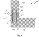
- tension elements 130 run through the lead-through areas 10' in the molded block 1'.
- the tension elements 130 extending from the floor or ceiling plate 110 through the molded block 1' to the vertically running building wall 120 are designed to transmit tensile forces acting in the vertical direction and hold the building parts 110, 120 arranged one above the other at a predetermined distance from one another.
- the molded block 1' can be in the molded body 2', similar to Fig.2 shown, have an insulating section or body 8.
- Figure 4 shows an exemplary embodiment of the molded body 2 on the contact surface 4 and/or the support surface 6.
- the contact surface 4 and/or the support surface 6 has transfer projections 12, 12' designed as profile elements and can be referred to as a toothed joint, with surfaces 16, 16' offset parallel to one another and flanks 18 running obliquely thereto.
- a positive connection between the Contact areas of the molded block and a floor or ceiling plate arranged above it or the building wall 120 The same or a different design can also be provided downwards.
- the transfer projection(s) 22 are designed as a type of cuboid-shaped material projection, which is formed in particular in one piece or integrally with the molded body.
- the transfer projection 22 has flanks 24 running essentially at right angles to the base surface of the contact surface 4 and/or the support surface 6. This provides a right angle (90°), whereas the Figure 4 shows an obtuse angle ⁇ .
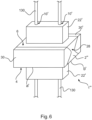
- Figure 6 shows a molded block 1" with a molded body 2" made of a concrete material, which has a substantially rectangular shape in the area of its contact surfaces 4, 6 to a respective floor slab or building wall.
- the molded body 2" has a material constriction 28 over its height in cross-section in at least one of its main longitudinal directions.
- the molded body 2" of the molded block 1" has, in particular in a cross-section running transversely to the long side a', an outer contour which preferably tapers evenly from the contact area 4 to approximately the middle of the molded block, which preferably widens evenly again from the middle of the molded block to the contact area 6 of the molded block.
- the long sides a' of the molded body 2" thus have a type of wedge-shaped depression.
- the molded component 1" shown further has, on its contact areas 4, 6 of the molded body 2", substantially vertically projecting transfer projections 22', which in the embodiment shown have a cuboid shape.
- the transfer projection has in the direction of the long side a' and in the direction of the long side b ⁇ of the mold block 1" has dimensions that are smaller than the dimensions of the mold body 2" at the level of the contact areas.
- the length of the transfer projection is to be understood as its dimension in the direction of or parallel to the long side a' of the mold block.
- the width of the transfer projection is to be understood as its dimension parallel to the long side b ⁇ of the mold block 1".
Landscapes
- Physics & Mathematics (AREA)
- Engineering & Computer Science (AREA)
- Architecture (AREA)
- Acoustics & Sound (AREA)
- Electromagnetism (AREA)
- Civil Engineering (AREA)
- Structural Engineering (AREA)
- Building Environments (AREA)
- Panels For Use In Building Construction (AREA)
Claims (15)
- Elément de construction moulé à disposer entre une paroi de bâtiment (120) armée et une plaque de sol ou de plafond (110) armée, pour supporter la paroi de bâtiment (120) sur la plaque de sol ou de plafond (110) ou pour supporter la plaque de plafond (110) sur la paroi de bâtiment (120), comprenant- un corps moulé (2, 2') composé d'un matériau de construction minéral, avec- une surface de contact au sol (4) pour la pose du corps moulé (2, 2') sur la plaque de sol ou de plafond (110) ou au-dessus de la paroi de bâtiment (120), et- une surface d'appui (6) s'étendant sensiblement parallèlement à la surface de contact au sol pour la plaque de plafond ou pour poser la paroi de bâtiment (120) sur celle-ci,dans lequel le corps moulé (2, 2') présente au moins une partie de corps isolant (8, 30, 30') ;et le corps moulé (2, 2') présente, sur sa surface de contact au sol (4) et/ou sa surface d'appui (6), une structure superficielle pour transmettre une poussée entre l'élément de construction moulé et la paroi de bâtiment ou la plaque de sol ou de plafond disposée au-dessous et/ou au-dessus de l'élément de construction moulé (1, 1'),caractérisé en ceque la partie de corps isolant (30, 30') est disposée sur les surfaces latérales du corps moulé (2'), etque l'élément de construction moulé présente au moins une zone de traversée (10, 10') s'étendant en particulier à partir de la surface de contact au sol (4) jusqu'à la surface d'appui (6) pour un élément de traction (130).
- Elément de construction moulé selon la revendication 1,
caractérisé en ce que le corps moulé (2, 2') présente, sur sa surface de contact au sol et sa surface d'appui (4, 6), une structure superficielle pour transmettre une poussée, dans lequel de préférence la poussée pouvant être transmise entre la paroi de bâtiment et le corps moulé et/ou entre la plaque de sol ou de plafond a une valeur au-dessus de 100 kN/m, de préférence une valeur au-dessus de 200 kN/m, de manière particulièrement préférée dans la direction longitudinale de la paroi de bâtiment une valeur au-dessus de 600 kN/m. - Elément de construction moulé selon la revendication 1 ou 2,
caractérisé en ce que le corps moulé (2, 2'), pour la réalisation de la structure superficielle sur la surface de contact au sol et/ou surface d'appui (4, 6), présente une rugosité de surface prédéfinie avec une profondeur de rugosité moyenne Rz ≥ 1,5 mm ou une hauteur de sommet de profil maximale Rp ≥ 1,1 mm, de préférence avec une profondeur de rugosité moyenne Rz ≥ 3,0 mm ou une hauteur de sommet de profil maximale Rp ≥ 2,2 mm. - Elément de construction moulé selon l'une quelconque des revendications précédentes,
caractérisé en ce que la paroi de bâtiment ou la plaque de sol ou de plafond est fabriquée à partir d'un béton coulé sur place avec un granulat prédéfini, et la rugosité de surface de la surface de contact au sol ou d'appui (4, 6) correspond à au moins un quart, de préférence la moitié, de la granulométrie du plus gros grain du mélange de grains du béton coulé sur place. - Elément de construction moulé selon l'une quelconque des revendications précédentes,
caractérisé en ce que la structure superficielle présente au moins une saillie de transmission (12, 12', 22, 22') faisant saillie sur la surface de contact au sol, de préférence sur la surface de contact au sol et la surface d'appui (4, 6) du corps moulé. - Elément de construction moulé selon la revendication 5,
caractérisé en ce que la saillie de transmission (12, 12', 22, 22') est réalisée comme au moins un élément profilé réalisé d'une seule pièce avec le corps moulé (2, 2') ou est réalisée au moins comme une partie profilée séparée, insérée dans la surface de contact au sol et/ou surface d'appui (4, 6) du corps moulé. - Elément de construction moulé selon la revendication 5 ou 6,
caractérisé en ce que la saillie de transmission (12, 12', 22, 22') présente des flancs latéraux pour la transmission de poussée, qui s'étendent de préférence à un angle obtus β par rapport à la surface d'appui ou de contact au sol (4, 6), en particulier dans la plage de 91 à 135° ou sont orientés à un angle droit par rapport à la surface de contact au sol et/ou surface d'appui. - Elément de construction moulé selon l'une quelconque des revendications 5 à 7,
caractérisé en ce que la saillie de transmission (12, 12', 22, 22') recouvre ou occupe plus de 20 %, de préférence plus de 40 %, de la surface de base totale de la surface de contact au sol ou surface d'appui (4, 6). - Elément de construction moulé selon l'une quelconque des revendications 5 à 8,
caractérisé en ce que l'élément profilé est réalisé comme un joint denté avec des flancs latéraux s'étendant de manière oblique ou comme une partie saillante individuelle avec des flancs latéraux perpendiculaires à la surface de contact au sol et/ou surface d'appui (4, 6), dans lequel de préférence l'élévation de l'élément profilé au-dessus de la surface de base sur la surface de contact au sol et/ou surface d'appui (4, 6) est supérieure ou égale à 10 mm. - Elément de construction moulé selon au moins l'une des revendications 6 à 9,
caractérisé en ce que respectivement au moins deux éléments profilés, avec une élévation identique et une distance prédéfinie l'un par rapport à l'autre, sont prévus sur la surface de contact au sol et/ou la surface d'appui (4, 6), dans lequel la distance présente au moins quatre fois, de préférence huit fois, une valeur de l'élévation. - Elément de construction moulé selon l'une quelconque des revendications précédentes,
caractérisé en ce que le corps moulé (2, 2') présente, sur sa surface de contact au sol et/ou surface d'appui (4, 6) au moins par endroits, une couche d'appui composée d'un matériau stratifié avec des propriétés élastiques souples, de préférence une couche élastomère. - Elément de construction moulé selon l'une quelconque des revendications précédentes,
caractérisé en ce que la zone de traversée termine dans une zone plane sur la surface de contact au sol et la surface d'appui (4, 6), qui sont sensiblement à plan parallèle l'une par rapport à l'autre. - Elément de construction moulé selon la revendication 12,
caractérisé par un corps de séparation ou d'étanchéité disposé fixement dans la zone de traversée (10, 10') pour l'élément de traction composé d'un matériau de préférence élastique. - Elément de construction moulé selon l'une quelconque des revendications précédentes,
caractérisé en ce que le corps moulé (2, 2') est fabriqué sensiblement à partir d'un matériau en béton, de préférence à partir d'un béton fibré à très haute résistance et/ou que le matériau de construction minéral présente un rapport sigma/lambda supérieur à 10, de préférence supérieur à 20, de manière particulièrement préférée supérieur à 45. - Partie de bâtiment (100) comprenant,- une plaque de sol ou de plafond (110),- une paroi de bâtiment (120) disposée sensiblement verticalement sur ou sous la plaque de sol ou de plafond (110),- au moins un élément de construction moulé (1, 1') selon l'une quelconque des revendications 1 à 14 disposé entre la plaque de sol ou de plafond (110) et la paroi de bâtiment (120), dans lequel la partie de bâtiment (100) est en particuliercaractérisée par un élément de traction (130) s'étendant entre la paroi de bâtiment (120) et la plaque de sol de plafond (110) à travers l'élément de construction moulé (1, 1').
Priority Applications (3)
| Application Number | Priority Date | Filing Date | Title |
|---|---|---|---|
| EP17195439.9A EP3467221B1 (fr) | 2017-10-09 | 2017-10-09 | Élément moulé destiné à être placé entre un mur de construction et une plaque de sol ou de plafond, et section de construction pourvus d'un tel élément |
| HUE17195439A HUE067312T2 (hu) | 2017-10-09 | 2017-10-09 | Alakos építõelem egy megerõsített épületfal és egy megerõsített alap- vagy födémlemez között történõ elhelyezésre és épületrész ilyen alakos építõelemmel |
| EP24173256.9A EP4400668B1 (fr) | 2017-10-09 | 2017-10-09 | Élément moulé destiné à être placé entre un mur de construction et une plaque de sol ou de plafond, et section de construction pourvus d'un tel élément |
Applications Claiming Priority (1)
| Application Number | Priority Date | Filing Date | Title |
|---|---|---|---|
| EP17195439.9A EP3467221B1 (fr) | 2017-10-09 | 2017-10-09 | Élément moulé destiné à être placé entre un mur de construction et une plaque de sol ou de plafond, et section de construction pourvus d'un tel élément |
Related Child Applications (2)
| Application Number | Title | Priority Date | Filing Date |
|---|---|---|---|
| EP24173256.9A Division EP4400668B1 (fr) | 2017-10-09 | 2017-10-09 | Élément moulé destiné à être placé entre un mur de construction et une plaque de sol ou de plafond, et section de construction pourvus d'un tel élément |
| EP24173256.9A Division-Into EP4400668B1 (fr) | 2017-10-09 | 2017-10-09 | Élément moulé destiné à être placé entre un mur de construction et une plaque de sol ou de plafond, et section de construction pourvus d'un tel élément |
Publications (3)
| Publication Number | Publication Date |
|---|---|
| EP3467221A1 EP3467221A1 (fr) | 2019-04-10 |
| EP3467221C0 EP3467221C0 (fr) | 2024-07-03 |
| EP3467221B1 true EP3467221B1 (fr) | 2024-07-03 |
Family
ID=60051404
Family Applications (2)
| Application Number | Title | Priority Date | Filing Date |
|---|---|---|---|
| EP24173256.9A Active EP4400668B1 (fr) | 2017-10-09 | 2017-10-09 | Élément moulé destiné à être placé entre un mur de construction et une plaque de sol ou de plafond, et section de construction pourvus d'un tel élément |
| EP17195439.9A Active EP3467221B1 (fr) | 2017-10-09 | 2017-10-09 | Élément moulé destiné à être placé entre un mur de construction et une plaque de sol ou de plafond, et section de construction pourvus d'un tel élément |
Family Applications Before (1)
| Application Number | Title | Priority Date | Filing Date |
|---|---|---|---|
| EP24173256.9A Active EP4400668B1 (fr) | 2017-10-09 | 2017-10-09 | Élément moulé destiné à être placé entre un mur de construction et une plaque de sol ou de plafond, et section de construction pourvus d'un tel élément |
Country Status (2)
| Country | Link |
|---|---|
| EP (2) | EP4400668B1 (fr) |
| HU (1) | HUE067312T2 (fr) |
Families Citing this family (2)
| Publication number | Priority date | Publication date | Assignee | Title |
|---|---|---|---|---|
| AT522177B1 (de) * | 2019-06-17 | 2020-09-15 | Walter Eberl | Sockel für eine Holzwand |
| CN113356372B (zh) * | 2021-06-02 | 2022-11-04 | 新疆昌吉建设(集团)有限责任公司 | 一种装配式建筑用直角连接件 |
Family Cites Families (4)
| Publication number | Priority date | Publication date | Assignee | Title |
|---|---|---|---|---|
| CN2095896U (zh) * | 1991-03-09 | 1992-02-12 | 冯启文 | 榫式复合空心保温砌块 |
| DE10106222A1 (de) * | 2001-02-10 | 2002-08-14 | Schoeck Entwicklungsgmbh | Mauersteinförmiges Wärmedämmelement |
| PL2405065T3 (pl) | 2010-11-19 | 2014-09-30 | Georg Koch | Przenoszący siłę ściskającą i izolacyjny element połączeniowy |
| EP3296476B1 (fr) * | 2016-09-16 | 2024-04-24 | Schöck Bauteile GmbH | Dispositif de liaison d'un mur de bâtiment à une dalle de sol ou de plafond et élément de moulage d'un tel système |
-
2017
- 2017-10-09 EP EP24173256.9A patent/EP4400668B1/fr active Active
- 2017-10-09 HU HUE17195439A patent/HUE067312T2/hu unknown
- 2017-10-09 EP EP17195439.9A patent/EP3467221B1/fr active Active
Also Published As
| Publication number | Publication date |
|---|---|
| EP4400668A3 (fr) | 2024-08-07 |
| EP3467221C0 (fr) | 2024-07-03 |
| EP4400668A2 (fr) | 2024-07-17 |
| EP3467221A1 (fr) | 2019-04-10 |
| EP4400668B1 (fr) | 2026-04-08 |
| HUE067312T2 (hu) | 2024-10-28 |
Similar Documents
| Publication | Publication Date | Title |
|---|---|---|
| EP3690159B1 (fr) | Enveloppe de bâtiment et procédé d'isolement thermique des enveloppes de bâtiment en béton | |
| EP3085843B1 (fr) | Dispositif et procédé de couplage thermique de parties betonnées de bâtiment | |
| EP2410096B1 (fr) | Dispositif de coffrage et procédé de formation d'un évidement pendant le coulage d'un composant | |
| EP2486196B1 (fr) | Procédé et dispositif pour l'ajout postérieur d'une partie extérieure en saillie à une partie de bâtiment existante | |
| EP0059171B1 (fr) | Boulon et canon pour la prise et la transmission d'une force transversale | |
| WO2008092664A2 (fr) | Élément de construction | |
| EP3467223B1 (fr) | Élément moulé destiné à etre placé entre un mur de construction et une plaque de sol ou de plafond et section de construction pourvue d'un tel élément moulé | |
| EP3467221B1 (fr) | Élément moulé destiné à être placé entre un mur de construction et une plaque de sol ou de plafond, et section de construction pourvus d'un tel élément | |
| EP3296476B1 (fr) | Dispositif de liaison d'un mur de bâtiment à une dalle de sol ou de plafond et élément de moulage d'un tel système | |
| EP1482101A1 (fr) | Elément de construction, procédé pour fabriquer des éléments de construction et moyens de liaison pour élément de construction | |
| EP3754125B1 (fr) | Élément de construction pour le montage dans des joints de dilatation de bâtiments | |
| EP4086401B1 (fr) | Composant denté thermoisolant et procédé de construction d'une section de bâtiment | |
| EP3839162B1 (fr) | Composant thermo-isolant destiné à être utilisé dans une fente de séparation entre deux parties de construction | |
| EP3296478A1 (fr) | Dispositif de liaison d'un mur de bâtiment à une dalle de sol ou de plafond et élément de moulage d'un tel système | |
| EP3663474B1 (fr) | Dispositif d'isolement thermique entre un mur de bâtiment bétonné et un plancher, ainsi que procédé de fabrication | |
| EP3912778B1 (fr) | Procédé de fabrication à plat d'une pièce porteuse verticale préfabriquée en béton et pièce porteuse verticale préfabriquée en béton | |
| EP3467220B1 (fr) | Partie de bâtiment et procédé de fabrication d'une telle partie de bâtiment | |
| CH717894A2 (de) | Wandbauelement, insbesondere Fassadenwand-Bauelement. | |
| EP3663475B1 (fr) | Dispositif d'isolement thermique entre un mur de bâtiment bétonné et un plancher, ainsi que procédé de fabrication | |
| DE20310430U1 (de) | Installationskanal | |
| EP3296477B1 (fr) | Élément de moulage pour disposer sur une dalle de sol ou sur ou sous une dalle de plafond et procédé de fabrication de l'élément de moulage | |
| AT523024A1 (de) | Gebäudekonstruktion und Verfahren zur Bildung derselben | |
| CH695274A5 (de) | Kragplattenanschlusselement mit integriertem Gleitlager. |
Legal Events
| Date | Code | Title | Description |
|---|---|---|---|
| PUAI | Public reference made under article 153(3) epc to a published international application that has entered the european phase |
Free format text: ORIGINAL CODE: 0009012 |
|
| STAA | Information on the status of an ep patent application or granted ep patent |
Free format text: STATUS: THE APPLICATION HAS BEEN PUBLISHED |
|
| AK | Designated contracting states |
Kind code of ref document: A1 Designated state(s): AL AT BE BG CH CY CZ DE DK EE ES FI FR GB GR HR HU IE IS IT LI LT LU LV MC MK MT NL NO PL PT RO RS SE SI SK SM TR |
|
| AX | Request for extension of the european patent |
Extension state: BA ME |
|
| STAA | Information on the status of an ep patent application or granted ep patent |
Free format text: STATUS: REQUEST FOR EXAMINATION WAS MADE |
|
| 17P | Request for examination filed |
Effective date: 20191010 |
|
| RBV | Designated contracting states (corrected) |
Designated state(s): AL AT BE BG CH CY CZ DE DK EE ES FI FR GB GR HR HU IE IS IT LI LT LU LV MC MK MT NL NO PL PT RO RS SE SI SK SM TR |
|
| STAA | Information on the status of an ep patent application or granted ep patent |
Free format text: STATUS: EXAMINATION IS IN PROGRESS |
|
| 17Q | First examination report despatched |
Effective date: 20220112 |
|
| GRAP | Despatch of communication of intention to grant a patent |
Free format text: ORIGINAL CODE: EPIDOSNIGR1 |
|
| STAA | Information on the status of an ep patent application or granted ep patent |
Free format text: STATUS: GRANT OF PATENT IS INTENDED |
|
| INTG | Intention to grant announced |
Effective date: 20230428 |
|
| P01 | Opt-out of the competence of the unified patent court (upc) registered |
Effective date: 20230522 |
|
| GRAJ | Information related to disapproval of communication of intention to grant by the applicant or resumption of examination proceedings by the epo deleted |
Free format text: ORIGINAL CODE: EPIDOSDIGR1 |
|
| STAA | Information on the status of an ep patent application or granted ep patent |
Free format text: STATUS: EXAMINATION IS IN PROGRESS |
|
| GRAP | Despatch of communication of intention to grant a patent |
Free format text: ORIGINAL CODE: EPIDOSNIGR1 |
|
| STAA | Information on the status of an ep patent application or granted ep patent |
Free format text: STATUS: GRANT OF PATENT IS INTENDED |
|
| INTC | Intention to grant announced (deleted) | ||
| RAP3 | Party data changed (applicant data changed or rights of an application transferred) |
Owner name: SCHOECK BAUTEILE GMBH |
|
| INTG | Intention to grant announced |
Effective date: 20230831 |
|
| GRAJ | Information related to disapproval of communication of intention to grant by the applicant or resumption of examination proceedings by the epo deleted |
Free format text: ORIGINAL CODE: EPIDOSDIGR1 |
|
| STAA | Information on the status of an ep patent application or granted ep patent |
Free format text: STATUS: EXAMINATION IS IN PROGRESS |
|
| GRAS | Grant fee paid |
Free format text: ORIGINAL CODE: EPIDOSNIGR3 |
|
| STAA | Information on the status of an ep patent application or granted ep patent |
Free format text: STATUS: GRANT OF PATENT IS INTENDED |
|
| GRAP | Despatch of communication of intention to grant a patent |
Free format text: ORIGINAL CODE: EPIDOSNIGR1 |
|
| INTC | Intention to grant announced (deleted) | ||
| INTG | Intention to grant announced |
Effective date: 20240123 |
|
| GRAA | (expected) grant |
Free format text: ORIGINAL CODE: 0009210 |
|
| STAA | Information on the status of an ep patent application or granted ep patent |
Free format text: STATUS: THE PATENT HAS BEEN GRANTED |
|
| AK | Designated contracting states |
Kind code of ref document: B1 Designated state(s): AL AT BE BG CH CY CZ DE DK EE ES FI FR GB GR HR HU IE IS IT LI LT LU LV MC MK MT NL NO PL PT RO RS SE SI SK SM TR |
|
| REG | Reference to a national code |
Ref country code: CH Ref legal event code: EP |
|
| REG | Reference to a national code |
Ref country code: DE Ref legal event code: R096 Ref document number: 502017016223 Country of ref document: DE |
|
| U01 | Request for unitary effect filed |
Effective date: 20240703 |
|
| P04 | Withdrawal of opt-out of the competence of the unified patent court (upc) registered |
Free format text: CASE NUMBER: APP_40287/2024 Effective date: 20240706 |
|
| U07 | Unitary effect registered |
Designated state(s): AT BE BG DE DK EE FI FR IT LT LU LV MT NL PT SE SI Effective date: 20240710 |
|
| REG | Reference to a national code |
Ref country code: HU Ref legal event code: AG4A Ref document number: E067312 Country of ref document: HU |
|
| U20 | Renewal fee for the european patent with unitary effect paid |
Year of fee payment: 8 Effective date: 20240927 |
|
| P05 | Withdrawal of opt-out of the competence of the unified patent court (upc) changed |
Free format text: CASE NUMBER: APP_40287/2024 Effective date: 20240710 |
|
| PG25 | Lapsed in a contracting state [announced via postgrant information from national office to epo] |
Ref country code: NO Free format text: LAPSE BECAUSE OF FAILURE TO SUBMIT A TRANSLATION OF THE DESCRIPTION OR TO PAY THE FEE WITHIN THE PRESCRIBED TIME-LIMIT Effective date: 20241003 |
|
| PG25 | Lapsed in a contracting state [announced via postgrant information from national office to epo] |
Ref country code: PL Free format text: LAPSE BECAUSE OF FAILURE TO SUBMIT A TRANSLATION OF THE DESCRIPTION OR TO PAY THE FEE WITHIN THE PRESCRIBED TIME-LIMIT Effective date: 20240703 Ref country code: GR Free format text: LAPSE BECAUSE OF FAILURE TO SUBMIT A TRANSLATION OF THE DESCRIPTION OR TO PAY THE FEE WITHIN THE PRESCRIBED TIME-LIMIT Effective date: 20241004 |
|
| PG25 | Lapsed in a contracting state [announced via postgrant information from national office to epo] |
Ref country code: IS Free format text: LAPSE BECAUSE OF FAILURE TO SUBMIT A TRANSLATION OF THE DESCRIPTION OR TO PAY THE FEE WITHIN THE PRESCRIBED TIME-LIMIT Effective date: 20241103 |
|
| PG25 | Lapsed in a contracting state [announced via postgrant information from national office to epo] |
Ref country code: CZ Free format text: LAPSE BECAUSE OF FAILURE TO SUBMIT A TRANSLATION OF THE DESCRIPTION OR TO PAY THE FEE WITHIN THE PRESCRIBED TIME-LIMIT Effective date: 20240703 Ref country code: HR Free format text: LAPSE BECAUSE OF FAILURE TO SUBMIT A TRANSLATION OF THE DESCRIPTION OR TO PAY THE FEE WITHIN THE PRESCRIBED TIME-LIMIT Effective date: 20240703 |
|
| PG25 | Lapsed in a contracting state [announced via postgrant information from national office to epo] |
Ref country code: ES Free format text: LAPSE BECAUSE OF FAILURE TO SUBMIT A TRANSLATION OF THE DESCRIPTION OR TO PAY THE FEE WITHIN THE PRESCRIBED TIME-LIMIT Effective date: 20240703 Ref country code: RS Free format text: LAPSE BECAUSE OF FAILURE TO SUBMIT A TRANSLATION OF THE DESCRIPTION OR TO PAY THE FEE WITHIN THE PRESCRIBED TIME-LIMIT Effective date: 20241003 |
|
| PG25 | Lapsed in a contracting state [announced via postgrant information from national office to epo] |
Ref country code: RS Free format text: LAPSE BECAUSE OF FAILURE TO SUBMIT A TRANSLATION OF THE DESCRIPTION OR TO PAY THE FEE WITHIN THE PRESCRIBED TIME-LIMIT Effective date: 20241003 Ref country code: PL Free format text: LAPSE BECAUSE OF FAILURE TO SUBMIT A TRANSLATION OF THE DESCRIPTION OR TO PAY THE FEE WITHIN THE PRESCRIBED TIME-LIMIT Effective date: 20240703 Ref country code: NO Free format text: LAPSE BECAUSE OF FAILURE TO SUBMIT A TRANSLATION OF THE DESCRIPTION OR TO PAY THE FEE WITHIN THE PRESCRIBED TIME-LIMIT Effective date: 20241003 Ref country code: IS Free format text: LAPSE BECAUSE OF FAILURE TO SUBMIT A TRANSLATION OF THE DESCRIPTION OR TO PAY THE FEE WITHIN THE PRESCRIBED TIME-LIMIT Effective date: 20241103 Ref country code: HR Free format text: LAPSE BECAUSE OF FAILURE TO SUBMIT A TRANSLATION OF THE DESCRIPTION OR TO PAY THE FEE WITHIN THE PRESCRIBED TIME-LIMIT Effective date: 20240703 Ref country code: GR Free format text: LAPSE BECAUSE OF FAILURE TO SUBMIT A TRANSLATION OF THE DESCRIPTION OR TO PAY THE FEE WITHIN THE PRESCRIBED TIME-LIMIT Effective date: 20241004 Ref country code: ES Free format text: LAPSE BECAUSE OF FAILURE TO SUBMIT A TRANSLATION OF THE DESCRIPTION OR TO PAY THE FEE WITHIN THE PRESCRIBED TIME-LIMIT Effective date: 20240703 Ref country code: CZ Free format text: LAPSE BECAUSE OF FAILURE TO SUBMIT A TRANSLATION OF THE DESCRIPTION OR TO PAY THE FEE WITHIN THE PRESCRIBED TIME-LIMIT Effective date: 20240703 |
|
| PG25 | Lapsed in a contracting state [announced via postgrant information from national office to epo] |
Ref country code: SM Free format text: LAPSE BECAUSE OF FAILURE TO SUBMIT A TRANSLATION OF THE DESCRIPTION OR TO PAY THE FEE WITHIN THE PRESCRIBED TIME-LIMIT Effective date: 20240703 |
|
| PG25 | Lapsed in a contracting state [announced via postgrant information from national office to epo] |
Ref country code: SK Free format text: LAPSE BECAUSE OF FAILURE TO SUBMIT A TRANSLATION OF THE DESCRIPTION OR TO PAY THE FEE WITHIN THE PRESCRIBED TIME-LIMIT Effective date: 20240703 |
|
| PLBE | No opposition filed within time limit |
Free format text: ORIGINAL CODE: 0009261 |
|
| STAA | Information on the status of an ep patent application or granted ep patent |
Free format text: STATUS: NO OPPOSITION FILED WITHIN TIME LIMIT |
|
| 26N | No opposition filed |
Effective date: 20250404 |
|
| PG25 | Lapsed in a contracting state [announced via postgrant information from national office to epo] |
Ref country code: MC Free format text: LAPSE BECAUSE OF FAILURE TO SUBMIT A TRANSLATION OF THE DESCRIPTION OR TO PAY THE FEE WITHIN THE PRESCRIBED TIME-LIMIT Effective date: 20240703 |
|
| PG25 | Lapsed in a contracting state [announced via postgrant information from national office to epo] |
Ref country code: IE Free format text: LAPSE BECAUSE OF NON-PAYMENT OF DUE FEES Effective date: 20241009 |
|
| U20 | Renewal fee for the european patent with unitary effect paid |
Year of fee payment: 9 Effective date: 20250925 |
|
| REG | Reference to a national code |
Ref country code: CH Ref legal event code: U11 Free format text: ST27 STATUS EVENT CODE: U-0-0-U10-U11 (AS PROVIDED BY THE NATIONAL OFFICE) Effective date: 20251101 |
|
| PGFP | Annual fee paid to national office [announced via postgrant information from national office to epo] |
Ref country code: HU Payment date: 20251010 Year of fee payment: 9 |
|
| PG25 | Lapsed in a contracting state [announced via postgrant information from national office to epo] |
Ref country code: RO Free format text: LAPSE BECAUSE OF FAILURE TO SUBMIT A TRANSLATION OF THE DESCRIPTION OR TO PAY THE FEE WITHIN THE PRESCRIBED TIME-LIMIT Effective date: 20240703 |
|
| PGFP | Annual fee paid to national office [announced via postgrant information from national office to epo] |
Ref country code: GB Payment date: 20251024 Year of fee payment: 9 |
|
| PGFP | Annual fee paid to national office [announced via postgrant information from national office to epo] |
Ref country code: CH Payment date: 20251101 Year of fee payment: 9 |
|
| PG25 | Lapsed in a contracting state [announced via postgrant information from national office to epo] |
Ref country code: CY Free format text: LAPSE BECAUSE OF FAILURE TO SUBMIT A TRANSLATION OF THE DESCRIPTION OR TO PAY THE FEE WITHIN THE PRESCRIBED TIME-LIMIT; INVALID AB INITIO Effective date: 20171009 |