EP3469898A1 - Machine d'épandage agricole et procédé de commande d'une telle machine d'épandage - Google Patents
Machine d'épandage agricole et procédé de commande d'une telle machine d'épandage Download PDFInfo
- Publication number
- EP3469898A1 EP3469898A1 EP18195026.2A EP18195026A EP3469898A1 EP 3469898 A1 EP3469898 A1 EP 3469898A1 EP 18195026 A EP18195026 A EP 18195026A EP 3469898 A1 EP3469898 A1 EP 3469898A1
- Authority
- EP
- European Patent Office
- Prior art keywords
- distributor
- edge structure
- actuator
- orientation
- agricultural
- Prior art date
- Legal status (The legal status is an assumption and is not a legal conclusion. Google has not performed a legal analysis and makes no representation as to the accuracy of the status listed.)
- Granted
Links
Images

Classifications
-
- A—HUMAN NECESSITIES
- A01—AGRICULTURE; FORESTRY; ANIMAL HUSBANDRY; HUNTING; TRAPPING; FISHING
- A01M—CATCHING, TRAPPING OR SCARING OF ANIMALS; APPARATUS FOR THE DESTRUCTION OF NOXIOUS ANIMALS OR NOXIOUS PLANTS
- A01M7/00—Special adaptations or arrangements of liquid-spraying apparatus for purposes covered by this subclass
- A01M7/005—Special arrangements or adaptations of the spraying or distributing parts, e.g. adaptations or mounting of the spray booms, mounting of the nozzles, protection shields
- A01M7/0053—Mounting of the spraybooms
- A01M7/0057—Mounting of the spraybooms with active regulation of the boom position
Definitions
- the present invention relates to an agricultural distribution machine for discharging liquids and / or granular or granular materials having the features of the preamble of independent claim 1.
- the invention also relates to a method for controlling and / or regulating a distributor with the features of the preamble of the independent method claim 12th
- distribution machines for the application of a wide variety of active ingredients such as liquids and / or granular or granular materials use. Frequently, such agricultural distribution machines are also referred to as field sprayers.
- the distributing machines generally have a distribution device extending in the working position transversely to the direction of travel.
- the distribution machines can be designed both as a self-propelled or as attached to a towing vehicle or mounted distribution machines.
- the distributing devices or the distributing devices also referred to as spraying booms, sometimes have large working widths of twenty meters and more, whereby such distributing devices are generally subdivided into a plurality of linkage segments, each of which is arranged so as to be pivotable about upright axles and thus, i.a. for a transport journey, these upright axles can be folded into a maximum permissible transport width for the transport journey.
- the agricultural distributor is used for dispensing liquid and / or solid active substances and includes, inter alia, arranged transversely to the direction of travel distribution device with a central part and about vertical or upright pivoting and rotating axes on the central part rotatably mounted lateral sections, wherein the pivoting and rotating axes with damping elements are provided and arranged between the central part and the side sections means for reducing a spring travel of the lateral sections.
- the damping elements can be controlled or regulated via a control unit as a function of the respectively current movement type of the distributor.
- Comparable systems go from the EP 2 835 050 A1 as well as the EP 2 837 285 A1 out.
- means for detecting these vibrations are provided.
- the means may in particular be a camera system. Based on the detected by the camera lifting, yawing and Wankschulen the optimal steps for correcting and optimizing the movements of the distribution device are derived, in turn, the rolling movements, in particular by means of a powered by electrical energy damper system, are regulated. Also, this system does not see a controlled adjustment of the distribution device, for example. To be able to edit corners or curves of arable land and no consideration of boundaries and edge structures of the arable land before.
- a method for correcting position coordinates stored in a memory of a working computer of an agricultural distribution machine is derived from US Pat EP 2 983 010 A1 out.
- the method described here should be characterized by two preferably mutually perpendicularly oriented shifting operations of the stored position coordinates relative to the current position, wherein the first of these shifting operations is performed on the basis of position and / or moving direction data of the working machine, preferably determined on the basis of the direction of travel.
- a controlled adjustment of the distribution device for example, to be able to edit corners or peaks or curves or the like.
- the method also does not exist.
- the route planning system includes position determination devices for determining a current position of the relevant distribution machines, route planning data determination devices necessary route planning data to provide, for example.
- the route planning data By automatic detection of the position data and other additional information and / or by input by an operator and communication facilities to send the route planning data.
- security areas can be defined, for example, on roadsides where the agricultural machinery can not drive.
- the definition of the optimal route is based solely on the aspect of the routes or the lanes of the respective machines, without taking into account an optimal full-surface processing or treatment of the agricultural area. Also find corners and edge structures of the agricultural area no consideration for controlling distribution devices or working devices of agricultural machinery.
- a distributor with an improved system for section control goes out of the EP 2 918 157 B1 out.
- the system provides an angle sensor that can measure the angle between a towing vehicle and the distribution device.
- the distributor comprises a position sensor, which can measure the position of a tractor of the distributor or the position of the distributor and thus the sections of the distributor depending on the position and the angle are respectively switched accordingly.
- An active change of the position or the angle of the distribution device with respect to the distribution machine in order to be able to process, for example, certain areas of the field, does not provide the system.
- the shows EP 1 716 754 B1 an agricultural distribution machine with a frame and a storage container disposed on the frame and with a arranged on the frame by means of a suspension distributor, which is suspended about an upright axis relative to the frame pivotable, wherein between the frame and the distributor at least one, preferably one electronic control device controllable, motorized actuator for adjusting the distributor linkage is provided about the upright axis, and that means are provided by means of which the distribution device by means of the actuator always perpendicular to the desired direction or to the lane of the distributor is aligned, ie in particular when cornering the distributor is always aligned at right angles to the frame or to the direction of travel of the distributor, whereby it is not possible to treat corners or peaks or curves or the like.
- the invention is therefore based on the object to provide an agricultural distributor with a distributor with a large working width and a method for controlling this distributor, with which it is simplified, blunt or acute or right angles having corners and curvy boundaries or edge structures of arable land edit or treat, without damaging the plant life and at the same time to avoid double treatments largely.
- the agricultural distribution machine can in this case be designed as a self-propelled or as a medium towing vehicle or as a mounted on a tractor distribution machine.
- the connection between the distributor and the tractor can be done in particular by means of a known draw device or a drawbar.
- the distribution machine may be designed as an autonomous vehicle, or be an autonomous distribution machine with distribution device.
- the distribution machine comprises at least one frame for supporting the respective components, one or more storage containers for carrying and providing the respective Verteilguts and extending in a working position transverse to the direction distribution device, at which distribution device downwardly directed dispensing nozzles for dispensing and distributing the respective liquids and / or the granular or granular substances are attached.
- the distribution device is movably arranged on the frame, wherein the distribution device for this purpose, for example, by means of a parallelogram or by means of a linear slide in its height adjustable to the frame attached, but can also be grown directly on the frame.
- the attachment of the distributor is in each case based only on the frame, whereby, however, a connection example.
- a parallelogram or the like By means of a parallelogram or the like.
- Intermediate frame between the distributor and the frame is not excluded, but the term frame alike on such Embodiments relates or includes such embodiments, ie when attaching the distributor on the frame or on the connection by means of a parallelogram or other intermediate segment or intermediate frame can not be excluded.
- the distribution device may be divided into a plurality of rod segments, for example.
- a distribution linkage of a distribution machine may be made of e.g. a total of eleven rod segments put together, which are each pivotable about upright axes to each other.
- any further number of articulated rod segments connected to one another would also be conceivable.
- the pivoting of the respective rod segments or the distribution device about the upright axles is effected by means of at least one controllable by an electronic control device motor actuator.
- the linkage segments and / or the upright axles and / or the at least one motorized actuator are assigned sensors such that they can detect an actual value with respect to the existing orientation or the current relative position and forward or output to a control device.
- the distribution device can be an axis of rotation extending in the direction of travel by means of at least one drive element corresponding to a bottom contour be pivoted so as to achieve the most accurate adaptation to the respective contour of the ground or the respective horizon or to achieve as equal distances between the distributor and the ground contour or to a plant stock.
- the distributor may comprise at least one chassis formed from at least two wheels or one or more steerable axles, wherein the wheels may in turn be arranged pivotable or steerable relative to the frame via upright axles, and at least one of them may be used for steering electronic control device can be provided controllable motor actuator.
- the chassis and / or the upright axles and / or the at least one actuator sensors may be assigned such that they can detect an actual value with respect to the existing orientation or the current relative position and forward or output to a control device.
- the agricultural spreader may include four wheels, wherein each two opposite wheels form a chassis and an axle and wherein at least the wheels of the front axle or only the wheels of the rear axle or the wheels of both axles respectively.
- each two opposite wheels form a chassis and an axle and wherein at least the wheels of the front axle or only the wheels of the rear axle or the wheels of both axles respectively.
- the axles may also be mounted on a frame supporting the components of the spreader.
- the distributor may include a distributor motor driving engine and a cabin.
- the agricultural distributor as drawn by a towing vehicle distributor, they have for connection to the towing vehicle a traction device, which in turn the traction device can be mounted about an upright axis pivotable or steerable to the frame and also by means of a motorized actuator a position of the pulling device with respect to the frame can be changed so as to steer the distributor.
- the distribution machine assigned and / or provided with a control device of this contour determination means are provided and that a control of the at least one motorized actuator for pivoting the Gestuckedesegmente and / or the distribution device in response to a detected current orientation or relative position of the rod segments and / or the distribution device and the respective existing or detected edge structure is carried out.
- the sensors for detecting the respective orientation or the respective relative position may in particular be angle potentiometers or angle sensors or position sensors or the like. Linear measuring systems would also be conceivable or usable. In general, therefore, any sensors would be conceivable by means of which a current orientation can be detected or determined. By means of the sensors is thus, for example, a steering angle of the wheels and / or the pulling device with respect to the Frame captured and evaluated. In addition, by means of the sensors, it is also possible to determine a position of the distributor in relation to the frame.
- the signals detected by the sensors can be correspondingly transmitted to the control device, wherein the signals are subsequently converted into corresponding values of the relative positions by means of a control program stored in the control device.
- the distributor can each be guided along a definable or a defined lane; i.e. that, for example, the wheels or the pulling device or the distributing machine is / are steered in such a way that it follows / follow a lane, which in turn can prevent or reduce overrunning of plants.
- a control device in connection lane detection devices may be provided.
- lanes for example, so-called. Tramlines can be used, which can be detected by means of additional measuring means or their data can be stored in the control device.
- a laser scanner and / or a camera or a camera system and / or a radar sensor could be provided as lane detection devices.
- a GPS system could be provided on the distributor for tracking.
- the respective lanes are read out of a database or that the lane is calculated on the basis of a determined curve radius by means of a control program stored in the control device.
- the distribution machine is attached to or connected to a towing vehicle, it could also be provided that the towing vehicle or its control unit is connected to the control device of the distribution machine and, in turn, the towing vehicle or its steering and / or its drive unit to be autonomously resp automatically based on the existing edge structure and the detected current relative position using the Control device of the distributor is controlled.
- the towing vehicle or its control unit is connected to the control device of the distribution machine and, in turn, the towing vehicle or its steering and / or its drive unit to be autonomously resp automatically based on the existing edge structure and the detected current relative position using the Control device of the distributor is controlled.
- the towing vehicle or its control unit is connected to the control device of the distribution machine and, in turn, the towing vehicle or its steering and / or its drive unit to be autonomously resp automatically based on the existing edge structure and the detected current relative position using the Control device of the distributor is controlled.
- the towing vehicle or its steering and / or its drive unit could also be overridden by an operator performed steering and drive commands.
- the detected edge structure could be, for example, a field edge or a field end or else an edge of the plant population, i. so the transition to another plant variety could be detected.
- an arable area can have an edge structure composed of several sides, which edge structure can also include several corners with different angles to one another.
- edge structures which have curves or which corners and curves would also be conceivable.
- tramlines could be determined as a boundary structure.
- Fences would also be detectable as marginal structures or could be evaluated. This also overlaps and double treatments can be further avoided.
- already treated or already processed areas of the plant stand or the respective arable land could be recorded as a marginal structure. Roads or paths can also be recognized or recorded as a border structure.
- the edge structures could each be stored in the control device or the control device could retrieve corresponding data from a database.
- a GPS system can be present at the distributor or can be in communication with the control unit. It would also be conceivable to use one or more laser scanners. One or more cameras or a camera system could also be used. In addition, radar sensors could also be used. A combination of several of the aforementioned systems would be conceivable. Thus, for example, by combining a GPS system with a sensor or a camera, the respective edge structure could be detected even more accurately.
- GPS system both in the determination of the edge structure as well as the determination of lanes as a generic term for any Satellite-based system or stands for any positioning system. So if in each case of the GPS system is mentioned, so here, for example, the Russian GLONASS system or the European GALILEO system or the Chinese BEIDOU system, etc. are included.
- the respective edge structure could be determined or calculated on the basis of a curve radius determined using, for example, a gyroscope and a control program stored in the control device.
- the respective edge structure could be retrieved by means of the control device from a database.
- the orientation of the distributor could also be detected, for which purpose, for example.
- an angle sensor can be mounted between an towing vehicle and the distributor. Also could be attached to the chassis or on the wheels or their bearings steering angle sensors. Also could be attached to the distribution machine acceleration sensors or gyroscopes or gyroscopes. A combination of the aforementioned sensors would be conceivable or conceivable.
- a control program is stored in the control device which, taking into account the detected actual values of the orientation or the relative position and the detected or existing edge structure, generates a calculation for controlling the at least one motorized actuator , by means of the control program for this purpose, corresponding travel speeds of the actuator can be defined.
- the traversing speeds could also be further specified, taking into account and processing of various parameters, such as the current travel movements of the distributor, i. the greater, for example, the travel speed of the distributor is the faster the travel speed of the at least one motorized actuator could be.
- the distribution machine or its towing vehicle can be detected, for example, whether the distribution machine or its towing vehicle is moving forwards or backwards, or at what speed the distribution machine or its towing vehicle is being moved. It could also be detected whether the distributor or its towing vehicle is accelerated or decelerated.
- the traversing speeds could also be defined on the basis of various other parameters, so that in turn can be avoided by too fast or too slow pivoting double treatments and / or sub-treatments.
- the travel speed can be based on the travel speed of the distributor and / or on the basis of the application rate and / or on the basis of the distance and / or on the basis of the respectively detected relative positions.
- These parameters can, for example, again be detected by a variety of measuring means and processed by means of the stored in the control device control program.
- a control of the at least one motorized actuator is deactivated by a forward drive and activated by a reverse drive.
- the at least one motor actuator damping means to prevent so-called.
- Greed and pitching be assigned in the direction of travel, which may be unaffected by this and remain activated both when driving forward and when reversing.
- the yawing and pitching movements can be sensed, for example, with acceleration sensors and / or yaw rate sensors, etc., whose output signals can be evaluated in a corresponding manner.
- An actuation of the at least one actuator can take place in such a way that the distributor device and / or its linkage segments have an at least substantially parallel orientation to the existing edge structure or intersect the projected vertical planes of the distributor device or its linkage segments and the edge structure. Also, both the parallel orientation and the perpendicular orientation to the edge structure can be done in a definable offset, so that a scheme can be accelerated accordingly, but this is still sufficiently accurate to achieve a desired work result.
- the distribution device in addition to the steering and / or the pivoting of the distribution device or its linkage segments about the upright axles, the distribution device can also be pivoted or moved transversely to the direction of travel with, for this purpose, the distribution device, for example.
- the distribution device can be associated with at least one motor actuator, which in turn, for example, on the basis of an existing parallelogram on the frame or on a frame associated with the parallelogram Edge structure is driven accordingly and the distributor pivoted according to transverse to the direction of travel. This can also be done without leaving the lanes. Thus, edge structures or curves and corners can be treated even more precisely.
- sensors could also be present in order to determine the respective relative position.
- the untreated surfaces which result in each case from the pivoting transversely to the direction of travel could thus in turn be detected or defined as an edge structure and swiveled correspondingly on the basis of this edge structure during a connecting journey with the distributor to the distributor device and / or its linkage segments.
- the at least one motorized actuator may in particular be mounted between the frame and the distribution device or between the frame and a linkage segment or between two linkage segments, and operated hydraulically and / or pneumatically and / or electrically.
- the at least one actuator can be designed as a cylinder or linear drive or spindle drive or the like.
- hydraulic or pneumatic actuators can be used, which are controlled by an electric control or an electrically operated valve.
- an orientation of the distributor device or an orientation of the rod segments with respect to the edge structure can be calculated by means of a corresponding control program, and then the respective motorized actuator or a valve associated therewith can be correspondingly driven and thus the distributor or its distributor Distributor or its linkage segments are moved to a desired position.
- the respective motorized actuator can be correspondingly controlled on the basis of the control program and the distribution device and / or the linkage segments can be swiveled accordingly.
- the distributor can be steered by means of the drawbar or by means of the wheels to achieve at least substantially parallel and / or rectangular alignment with the existing edge structure by means of the distribution device or by means of the rod segments.
- both the distributor could be controlled according as well as the distributor and / or the boom segments are pivoted accordingly.
- a control of the actuators could also be such that the distributor follows the lanes, wherein the distributor or its rod segments are pivoted respectively based on the existing edge structure, so that the distributor or its rod segments of the edge structure parallel and / or follow at right angles.
- control device and “control program” are understood as a generic term for any type of influence on the at least one actuator, wherein the term “control device” also includes a “control” and vice versa, since a control with a control a feedback of the controlled variable.
- the control device can thus also be designed as a controller, in particular for controlling the at least one actuator.
- control device or the control program can be designed as electrical or hydraulic or pneumatic or as electro-pneumatic or electro-hydraulic control.
- the respective existing upright axes can be both vertically and diagonally or obliquely extending in space, but these are each aligned in particular such that by means of this or by rotation about these horizontal rotation movements of the attached to these elements or assemblies are generated.
- the entire distribution device can be pivoted such that they have an at least substantially parallel alignment with the edge structure.
- the distributing device or its linkage segments can be pivoted in such a way that a linkage segment has a substantially parallel alignment with an edge structure, and that a linkage segment has a largely parallel and perpendicular orientation to an edge structure.
- the distributor can each be guided along a definable or a defined lane, which means that their wheels and / or their traction device are directed such that they follow the lane.
- lane-finding devices may be provided for the distribution machine.
- a control of the actuators could also be such that the distributor follows the lanes, wherein the distributor or its linkage segments are pivoted respectively based on the existing edge structure, so that the distributor or its rod segments follow the edge structure parallel and / or rectangular ,
- the invention also proposes a method for controlling and / or regulating a distributor.
- the agricultural distribution machine can in this case be designed as a self-propelled or drawn by towing vehicle or as a mounted on a tractor distribution machine.
- the distribution machine may be designed as an autonomous vehicle or be an autonomous distribution machine with distribution device.
- the distribution machine comprises at least one frame for supporting the respective components, one or more storage containers for carrying and providing the respective Verteilguts and extending in a working position transverse to the direction distribution device, at which distribution device downwardly directed dispensing nozzles for dispensing and distributing the respective liquids and / or the granular or granular substances are attached.
- the distribution device is movably arranged on the frame, wherein the distribution device for this purpose, for example, by means of a parallelogram or by means of a linear slide in height adjustable to the frame attached but can also be mounted directly on the frame.
- the attachment of the distributor is in each case based only on the frame, whereby, however, a connection example.
- a parallelogram or the like By means of a parallelogram or the like.
- Intermediate frame between the distributor and the frame is not excluded, but the term frame alike on such Embodiments relates or includes such embodiments.
- the distribution device may be subdivided into a plurality of linkage segments, for example in a middle part and two side parts mounted pivotably on upright axles, whereby the side parts may in turn also be composed of a plurality of linkage segments which are also pivotable relative to one another by means of upright axles.
- the linkage segments and / or the upright axles and / or the at least one motorized actuator are assigned sensors such that they can detect an actual value with respect to the existing orientation or the current relative position and forward or output to a control device.
- the distributor may comprise at least one chassis formed from at least two wheels or one or more steerable axles, wherein the wheels may in turn be arranged pivotable or steerable relative to the frame via upright axles, and at least one of them may be used for steering electronic control device can be provided controllable motor actuator.
- the suspension and / or the upright axles and / or the at least one actuator, sensors may be assigned such that they can detect an actual value with respect to the existing orientation or the current relative position and forward or output to a control device.
- the agricultural distributor as drawn by a towing vehicle distributor, they have for connection to the towing vehicle a traction device, which in turn the traction device can be mounted about an upright axis pivotable or steerable to the frame and also by means of a motorized actuator a position of the pulling device with respect to the frame can be changed so as to steer the distributor.
- the detected edge structure could be, for example, a field edge or a field end or else an edge of the plant population, i. so the transition to another type of plant could be recognized.
- tramlines could be determined as a boundary structure.
- Fences would also be detectable as marginal structures or could be evaluated, thereby also overlaps and double treatments can be further avoided.
- already treated or already processed areas of the plant stand or the respective arable land could be recorded as a marginal structure. Roads or paths can also be recognized or recorded as a border structure.
- the edge structures could each be stored in the control device, or the control device could retrieve corresponding data from a database.
- contour detection devices are provided for detecting and / or evaluating an existing edge structure, associated with the distribution machine and / or with a control device, and that a control of the at least one motorized actuator for pivoting the linkage segments and / or the distribution device in response to a detected current orientation or relative position of the linkage segments and / or the distribution device and the respective existing or detected edge structure takes place.
- a GPS system can be present at the distributor or can be in communication with the control unit. It would also be conceivable to use one or more laser scanners. One or more cameras or a camera system could also be used. In addition, radar sensors could also be used. A combination of several of the aforementioned systems would be conceivable. Thus, for example, by combining a GPS system with a sensor or a camera, the respective edge structure could be detected even more accurately.
- the respective edge structure could be determined or calculated on the basis of a curve radius determined using, for example, a gyroscope and a control program stored in the control device.
- the respective edge structure could be retrieved by means of the control device from a database.
- the orientation of the distributor are also detected, for which purpose, for example, between an towing vehicle and the distributor an angle sensor can be mounted. Also could be attached to the chassis or on the wheels or their bearings steering angle sensors. Also could be attached to the distribution machine acceleration sensors or gyroscopes or gyroscopes. A combination of the aforementioned sensors would be conceivable or conceivable.
- a control program is stored in the control device which, taking into account the detected actual values of the orientation or the relative position and the detected or existing edge structure, a calculation for controlling the at least one motorized actuator created by means of the control program for this purpose, corresponding travel speeds of the actuator can be defined.
- the traversing speeds could also be further specified, taking into account and processing of various parameters, such as the current travel movements of the distributor, i. the greater, for example, the travel speed of the distributor is, the faster the travel speed of the at least one motorized actuator could be.
- the travel speeds could also be defined on the basis of various other parameters, so that in turn can be avoided by too fast or too slow pivoting double treatments and / or sub-treatments.
- the travel speed can be based on the travel speed of the distributor and / or on the basis of the application rate and / or on the basis of the distance and / or on the basis of the respectively detected relative positions.
- These parameters can, for example, again be detected by a variety of measuring means and processed by means of the stored in the control device control program.
- a control of the at least one motorized actuator is deactivated by a forward drive and activated by a reverse drive.
- the at least one motor actuator damping means to prevent so-called. Greed and pitching be assigned in the direction of travel, which may be unaffected by this and remain activated both when driving forward and when reversing.
- An actuation of the at least one actuator can take place in such a way that the distributor device and / or its linkage segments have an at least substantially parallel orientation to the existing edge structure or intersect the projected vertical planes of the distributor device or its linkage segments and the edge structure. Also, both the parallel orientation and the perpendicular orientation to the edge structure can be done in a definable offset, so that a scheme can be accelerated accordingly, but this is still sufficiently accurate to achieve a desired result.
- the distribution device in addition to the steering and / or the pivoting of the distribution device or its linkage segments about the upright axles, the distribution device can also be pivoted or moved transversely to the direction of travel with, for this purpose, the distribution device, for example.
- the distribution device By means of a For pivoting transversely to the direction of travel of the distribution device can be associated with at least one motor actuator, which in turn, for example, on the basis of an existing Edge structure is driven accordingly and the distributor pivoted according to transverse to the direction of travel. This can also be done without leaving the lanes. Thus, edge structures or curves and corners can be treated even more precisely.
- sensors could also be present in order to determine the respective relative position.
- the untreated surfaces which result in each case from the pivoting transversely to the direction of travel could thus in turn be detected or defined as an edge structure and swiveled correspondingly on the basis of this edge structure during a connecting journey with the distributor to the distributor device and / or its linkage segments.
- FIGS. 1 to 6 For the same or equivalent elements of the invention are in the FIGS. 1 to 6 in each case identical reference numerals used. Furthermore, for better clarity, only reference numerals in the individual figures are shown, which are required for the description of the respective figure.
- the illustrated embodiments are merely examples of how the inventive agricultural spreader or method of the invention may be configured and are not an exhaustive limitation.
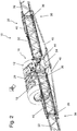
- FIGS. 1 to 3 out A variant of an agricultural distribution machine 10 according to the invention is based on FIGS. 1 to 3 out.
- the distributor 10 shown here is designed as a self-propelled machine, and the invention can also be used or used in towed or autonomous machines.
- the spreader 10 includes four wheels 12 supporting the spreader 10, with two opposing wheels 12 forming an undercarriage or axle, and at least the front axle 14 wheels 12 or only the rear axle 16 wheels 12 or the wheels 12 of both axles 14; 16 each, for example, about upright axles pivotally or steerable to the frame 18 are arranged.
- the axes 14; 16 are also mounted on a component 18 supporting the components of the distributor 10.
- the distributor 10 includes an engine 20 driving the distributor 10, a cabin 22 and a reservoir 24 for carrying and providing the respective liquid and / or the granular or granular substances or mixtures thereof.
- the frame 18 At the rear end of the frame 18 is assigned by means of actuators in height with respect to the frame 18 adjustable parallelogram 26. To which a transverse to the direction of travel 28 extending distributor 30 connects. It should again be noted that the embodiment by means of parallelogram 26 is only an attachment option of the distribution device 30. Likewise, it would also be possible to attach these directly to the frame 18. For the sake of simplicity, however, the attachment of the distributing device 30 will in each case be referred to the frame, whereby, however, a connection by means of a parallelogram 26 or another intermediate segment or intermediate frame is not precluded, but the term frame in connection with the attachment of the distribution device 30 equally refers to such embodiments.
- the distribution device is subdivided into a plurality of linkage segments 32 and consists of a middle part 34 and side parts 38 pivotally mounted on the right and left axles 36, wherein the side parts 38 are in turn composed of a plurality of linkage segments 32 which are also pivotable relative to one another by means of upright axles 36 ,
- the distribution machine 10 shown is composed, for example, of a total of eleven rod segments 32 which are pivotable relative to each other about upright axles 36.
- distribution device 30 or its middle part 34 could also be mounted pivotably about an upright axis on the frame 18 or on the parallelogram 26, whereby the entire distribution device 30 could also be pivoted accordingly.
- actuators 40 For pivoting the respective linkage segments 32 to each other or the distribution device 30 about the respective upright axles 36 are provided on these motor actuators 40, which in particular are controlled or actuated by an electronic control device 42 (see FIG. Fig. 6 ).
- actuators 40 according to the FIGS. 1 to 3 are each hydraulically operated cylinder or linear actuators, which are controlled by an electrically operated valve.
- pneumatic and / or electrically operated actuators 40 would also be usable.
- the existing motor actuators 40 can thus also acting on the distribution device 30 yawing and pitching movements (see FIG. Fig. 3 Arrows), which can be detected, for example, sensory, counteracted by a corresponding control of the actuators 40.
- the motor actuators 40 may be provided with damping means or the like to counteract corresponding yawing and pitching motions.
- the distribution device 30 can be pivoted about an axis of rotation 44 extending in the direction of travel 28 by means of at least one drive element 46 in accordance with a bottom contour, in order to achieve the most accurate adaptation to the respective contour of the ground or the respective horizon, or as far as possible distances between the distribution device 30 and the bottom contour or to reach a plant stock.
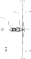
- the agricultural distribution machine 10 shown here is designed as an agricultural distribution machine 10 towed by means of a towing vehicle 46, it also being noted here again that the invention can also be used or used in self-propelled or autonomous machines.
- the distribution machine 10 is moved by means of a towing vehicle 46 over an arable area 48, wherein the arable area 48 has an edge structure 50 composed of several sides, which edge structure 50 also includes a plurality of corners 52 at different angles to one another.
- the connection between the distributor 10 and the towing vehicle by means of a traction device or a drawbar 54.
- edge structures are also conceivable, which have curves or edge structures which have corners 52 and curves.
- the distributor 10 also has an axle or a chassis with two steerable wheels 12, which wheels 12 can be pivoted or steered by means of a motorized actuator 40. It should be noted that in addition to a steering of the wheels 12, it would also be conceivable to direct the distributor 10 by means of a pivotable traction device 54 or to direct the distributor 10 both by means of the wheels 12 and by means of the traction device 54.
- the agricultural distribution machine 10 is guided by means of the towing vehicle 46 along lanes 56.
- the lanes 56 may be, for example, so-called tramlines. However, other lanes 56 would be conceivable, in particular, the respective lanes 56 can be detected and / or evaluated by means of lane detection devices 74, for example. These could also be stored in the control device 42 or corresponding data could be retrieved from the database by means of the control device 42 ,
- the respective edge structure 50 is determined by a variety of contour determining devices 58 such as a laser scanner and / or a camera and / or by means of a GPS system and / or by means of radar sensors or the like is detected and transmitted to the control device 42 according to or grown on the distributor 10 or are in communication with the control device 42.
- the respective edge structures 50 can also be correspondingly retrieved from a database by means of the control device 42 or read out.
- 36 sensors 60 are attached to the distribution device 30 and / or to the respective linkage segments 32 and / or to the respective steerable wheels 12 and / or the steerable drawbar 54 and / or the actuators 40 and to the upright axles that by means this is the current orientation or relative position 62 is determined.
- the control device 42 an orientation of the distributor device 30 or an alignment of its rod segments 32 with respect to the edge structure 50 can thus be calculated by a corresponding control program and then the respective motorized actuator 40 or a valve 64 assigned thereto can be correspondingly driven and thus the distribution machine 10 or its distribution device 30 or its linkage segments 32 are moved to a desired position.
- the respective motor actuator 40 is or will be driven accordingly based on the control program and the distributor device 30 and / or the linkage segments 32 are pivoted accordingly.
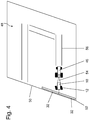
- the distribution machine 10 can also be deflected by means of the drawbar 54 or by means of the wheels 12 in order to achieve at least substantially parallel and / or rectangular alignment with the existing edge structure 50 by means of the distributing device 30 or by means of the linkage segments 32. Also, both the distributor 10 could be controlled accordingly and the distributor 30 and / or the rod segments 32 are pivoted accordingly.
- the entire distribution device 30 is pivoted such that it has an at least substantially parallel alignment with the edge structure 50
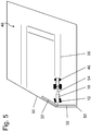
- the Fig. 5 The distribution device 30 or its linkage segments 32 have been pivoted in such a way that a linkage segment 32 has a substantially parallel alignment with an edge structure 50, and that a linkage segment 32 has a largely parallel and perpendicular orientation to an edge structure 50.
- the distribution machine 10 can each be guided along a definable or a defined lane 56, which means that their wheels 12 and / or their traction device 54 are directed in such a way that they follow the lane 56.
- the distribution machine 10 can be assigned and / or connected to a control device 42 Track detection means 74 may be provided.
- Track detection means 74 may be provided.
- a control of the actuators 40 could also be such that the distributor 10 follows the lanes 56, the distributor 30 or its rod segments 32, however, are pivoted respectively based on the existing edge structure 10, so that the distribution device 30 or the linkage segments 32 of the Edge structure 50 parallel and / or right angles follow.
- contour determination devices 58 which are connected to the distributor 10 or to the control device 42 are provided.
- the contour determination devices 58 can correspondingly detect and / or evaluate the respective edge structure 50 and transmit it to the control device 42.
- the contour determination devices 58 could also only transmit signals to the control device 42.
- an edge structure 50 could be correspondingly generated or evaluated.
- the contour determination device 58 could also be a database or they could be in connection with a database.
- sensors 60 are provided, for example. On the distributor 10 and / or on the upright axles 36 and / or the Actuators 40.
- the sensors 60 may in particular be any kind of position sensors, for example angular potentiometers or angle sensors or the like.
- the sensors 60 may respectively detect the respective relative position 62 and transmit it to the control device 42.
- the sensors 60 could also only communicate signals to the controller 42. The corresponding signals can then be converted into corresponding values of the relative positions 62 by means of a control program stored in the control device 42.
- the lanes 56 could be detected and / or evaluated by means of additional measuring means 66 or by means of lane detection devices 74.
- the lanes 56 could also be communicated to the controller 42 by means of a GPS system.
- the lanes 56 could be stored in a related to the controller 42 database.
- further measuring means 66 for determining the orientation of the distributor 10 could be provided, for example acceleration sensors or yaw rate sensors or gyroscopes or position sensors or the like.
- a valve 64 belonging to the respective motor actuator 40 is subsequently actuated by means of the control device 42, which subsequently controls the actuator 40 in such a manner that the distribution device 30 or the rod segments 32 or the distributor 10 has a take each desired position.
- a further control unit 70 and a drive unit 72 of the distributor 10 are controlled and thus the driving movements of the distributor 10 in turn depending on the relative position 62 and the edge structure 50 and, for example, also the lanes 56 controlled accordingly or regulated.
- a further control unit 70 and a drive unit 72 of the distributor 10 are controlled and thus the driving movements of the distributor 10 in turn depending on the relative position 62 and the edge structure 50 and, for example, also the lanes 56 controlled accordingly or regulated.
- a control program is stored in the control device 42 which, taking into account the detected actual values of the orientation or the relative position and the detected or existing edge structure 50, a calculation for Triggering of the motor actuator 40 created, whereby by means of the control program for this purpose corresponding travel speeds of the actuator 40 can be defined.
- the traversing speeds could also be considered and processed
- a variety of parameters 76 such as current driving movements 68 of the distributor 10 are further specified, that is, the greater the travel speed of the distributor 10, the faster the travel speed of the at least one motor actuator 40th
- the travel speeds could also be based on various other parameters 76, so that in turn can be avoided by too fast or too slow pivoting double treatments and / or sub-treatments.
- the travel speed can be based on the travel speed of the distributor 10 and / or on the basis of the application rate and / or on the basis of the travel distance and / or on the basis of the respectively detected relative positions.
- These parameters 76 can, for example, again be detected by a variety of measuring means 66 and processed by means of the stored in the control device 42 control program.
Landscapes
- Life Sciences & Earth Sciences (AREA)
- Engineering & Computer Science (AREA)
- Insects & Arthropods (AREA)
- Pest Control & Pesticides (AREA)
- Wood Science & Technology (AREA)
- Zoology (AREA)
- Environmental Sciences (AREA)
- Guiding Agricultural Machines (AREA)
Applications Claiming Priority (1)
| Application Number | Priority Date | Filing Date | Title |
|---|---|---|---|
| DE102017122420.3A DE102017122420A1 (de) | 2017-09-27 | 2017-09-27 | Landwirtschaftliche Verteilmaschine und Verfahren zur Steuerung einer derartigen Verteilmaschine |
Publications (2)
| Publication Number | Publication Date |
|---|---|
| EP3469898A1 true EP3469898A1 (fr) | 2019-04-17 |
| EP3469898B1 EP3469898B1 (fr) | 2024-02-14 |
Family
ID=63642615
Family Applications (1)
| Application Number | Title | Priority Date | Filing Date |
|---|---|---|---|
| EP18195026.2A Active EP3469898B1 (fr) | 2017-09-27 | 2018-09-18 | Machine d'épandage agricole et procédé de commande d'une telle machine d'épandage |
Country Status (2)
| Country | Link |
|---|---|
| EP (1) | EP3469898B1 (fr) |
| DE (1) | DE102017122420A1 (fr) |
Cited By (2)
| Publication number | Priority date | Publication date | Assignee | Title |
|---|---|---|---|---|
| EP3895532A1 (fr) * | 2020-04-16 | 2021-10-20 | HORSCH LEEB Application Systems GmbH | Système pour une machine agricole de travail, procédé de détermination d'une position des éléments de travail, ainsi que machine agricole de travail |
| CN114586759A (zh) * | 2022-03-08 | 2022-06-07 | 南京工业职业技术大学 | 一种用于小块农田作业的智能喷雾器及其使用方法 |
Families Citing this family (1)
| Publication number | Priority date | Publication date | Assignee | Title |
|---|---|---|---|---|
| US12532796B2 (en) * | 2024-02-26 | 2026-01-27 | Cnh Industrial America Llc | System and method for an agricultural machine |
Citations (6)
| Publication number | Priority date | Publication date | Assignee | Title |
|---|---|---|---|---|
| EP1716754A2 (fr) * | 2005-04-26 | 2006-11-02 | Amazonen-Werke H. Dreyer GmbH & Co. KG | Epandeur agricole |
| WO2012041743A1 (fr) * | 2010-10-01 | 2012-04-05 | Deere & Company | Combinaison constituée d'un véhicule tracteur et d'un appareil |
| EP2510784A1 (fr) * | 2011-04-14 | 2012-10-17 | Amazonen-Werke H. Dreyer GmbH & Co. KG | Rampe de pulvérisation à vitesse de repliage adaptative |
| DE102014102486A1 (de) * | 2014-02-26 | 2015-08-27 | Amazonen-Werke H. Dreyer Gmbh & Co. Kg | Landwirtschafltliche Verteilmaschine |
| EP2918157A2 (fr) * | 2014-02-18 | 2015-09-16 | Amazonen-Werke H. Dreyer GmbH & Co. KG | Machine agricole dotée d'une commande de section |
| US20160243575A1 (en) * | 2015-02-24 | 2016-08-25 | The Toro Company | Sprayer with automatically controlled laterally and angularly displaceable spray boom assembly |
Family Cites Families (6)
| Publication number | Priority date | Publication date | Assignee | Title |
|---|---|---|---|---|
| DE102006015204A1 (de) | 2006-03-30 | 2007-10-18 | Claas Selbstfahrende Erntemaschinen Gmbh | Verfahren zur Erstellung eines Routenplans für landwirtschaftliche Maschinensysteme |
| US8942893B2 (en) * | 2012-09-07 | 2015-01-27 | Trimble Navigation Limited | Predictive boom shape adjustment |
| DE102013214469A1 (de) | 2013-07-24 | 2015-01-29 | Horsch Leeb Application Systems Gmbh | Landwirtschaftliche Verteilmaschine mit Verteilvorrichtung und System zur Steuerung der Verteilvorrichtung |
| EP2835050B1 (fr) | 2013-08-09 | 2020-10-07 | Lemken GmbH & Co. KG | Pulvérisateur agricole comprenant une rampe d'pulvérisation |
| EP2837285B1 (fr) | 2013-08-09 | 2021-07-07 | Lemken GmbH & Co. KG | Rampe de pulvérisation d'un pulvérisateur agricole |
| DE102014111231A1 (de) | 2014-08-07 | 2016-02-11 | Amazonen-Werke H. Dreyer Gmbh & Co. Kg | Verfahren zur Korrektur in einem Speicher eines Arbeitsrechners gespeicherter Positionsdaten |
-
2017
- 2017-09-27 DE DE102017122420.3A patent/DE102017122420A1/de active Pending
-
2018
- 2018-09-18 EP EP18195026.2A patent/EP3469898B1/fr active Active
Patent Citations (6)
| Publication number | Priority date | Publication date | Assignee | Title |
|---|---|---|---|---|
| EP1716754A2 (fr) * | 2005-04-26 | 2006-11-02 | Amazonen-Werke H. Dreyer GmbH & Co. KG | Epandeur agricole |
| WO2012041743A1 (fr) * | 2010-10-01 | 2012-04-05 | Deere & Company | Combinaison constituée d'un véhicule tracteur et d'un appareil |
| EP2510784A1 (fr) * | 2011-04-14 | 2012-10-17 | Amazonen-Werke H. Dreyer GmbH & Co. KG | Rampe de pulvérisation à vitesse de repliage adaptative |
| EP2918157A2 (fr) * | 2014-02-18 | 2015-09-16 | Amazonen-Werke H. Dreyer GmbH & Co. KG | Machine agricole dotée d'une commande de section |
| DE102014102486A1 (de) * | 2014-02-26 | 2015-08-27 | Amazonen-Werke H. Dreyer Gmbh & Co. Kg | Landwirtschafltliche Verteilmaschine |
| US20160243575A1 (en) * | 2015-02-24 | 2016-08-25 | The Toro Company | Sprayer with automatically controlled laterally and angularly displaceable spray boom assembly |
Cited By (4)
| Publication number | Priority date | Publication date | Assignee | Title |
|---|---|---|---|---|
| EP3895532A1 (fr) * | 2020-04-16 | 2021-10-20 | HORSCH LEEB Application Systems GmbH | Système pour une machine agricole de travail, procédé de détermination d'une position des éléments de travail, ainsi que machine agricole de travail |
| EP3895532B1 (fr) | 2020-04-16 | 2023-08-23 | HORSCH LEEB Application Systems GmbH | Système pour une machine agricole de travail, procédé de détermination d'une position des éléments de travail, ainsi que machine agricole de travail |
| CN114586759A (zh) * | 2022-03-08 | 2022-06-07 | 南京工业职业技术大学 | 一种用于小块农田作业的智能喷雾器及其使用方法 |
| CN114586759B (zh) * | 2022-03-08 | 2022-11-04 | 南京工业职业技术大学 | 一种用于小块农田作业的智能喷雾器及其使用方法 |
Also Published As
| Publication number | Publication date |
|---|---|
| DE102017122420A1 (de) | 2019-03-28 |
| EP3469898B1 (fr) | 2024-02-14 |
Similar Documents
| Publication | Publication Date | Title |
|---|---|---|
| EP3772879B1 (fr) | Véhicule porteur agricole autonome | |
| EP3058820B1 (fr) | Procede de commande et/ou de reglage de mouvement d'un dispositif de distribution agricole | |
| EP2022329A2 (fr) | Dispositif de pulvérisation mobile doté d'une tige de pulvérisation et procédé de réglage de ses buses de pulvérisation | |
| DE102018108025A1 (de) | Landwirtschaftliches Fahrzeug | |
| EP3469898B1 (fr) | Machine d'épandage agricole et procédé de commande d'une telle machine d'épandage | |
| DE102019129206B4 (de) | Selbstfahrende und/oder mittels Zugfahrzeug gezogene Landmaschine und Verfahren zur Steuerung und/oder Regelung einer Höhenlage eines Verteilgestänges einer derartigen Landmaschine | |
| EP3732945B1 (fr) | Technique de la génération d'un profil de terrain à l'aide d'une machine agricole | |
| EP3466257B1 (fr) | Machine d'épandage agricole et procédé de commande d'une telle machine d'épandage | |
| EP3912468B1 (fr) | Procédé de commande et/ou de réglage du mouvement d'un dispositif d'épandage agricole | |
| EP3469899B1 (fr) | Machine d'épandage agricole et procédé de commande d'une telle machine d'épandage | |
| DE102021125360A1 (de) | Vorrichtung und Verfahren zur Bestimmung einer Lenkvorgabe für eine landwirtschaftliche Maschine | |
| DE102020106738A1 (de) | Kompensationssystem für eine Landmaschine, sowie Verteilmaschine und Verfahren zur Kompensation von Bodenunebenheiten für eine Landmaschine | |
| EP3469897B1 (fr) | Machine d'épandage agricole et procédé de commande d'une telle machine d'épandage | |
| EP3895532B1 (fr) | Système pour une machine agricole de travail, procédé de détermination d'une position des éléments de travail, ainsi que machine agricole de travail | |
| EP4014732B1 (fr) | Machine agricole à épandre et procédé de commande et/ou de régulation d'une machine agricole à épandre | |
| WO2023222478A1 (fr) | Machine de travail agricole à conduite autonome | |
| WO2022161904A1 (fr) | Véhicule porteur agricole autonome, et combinaison de machines agricoles autonomes | |
| EP3434088B1 (fr) | Dispositif agricole tracté | |
| EP4331356A1 (fr) | Machine de répartition agricole dotée d'une rampe de pulvérisation et procédé de commande de la position d'une telle rampe de pulvérisation | |
| EP4364546A1 (fr) | Procédé, dispositif de commande et système de direction pour la direction automatisée d'un véhicule agricole ainsi que véhicule agricole | |
| EP4453682A1 (fr) | Système de configuration et procédé de mise en oeuvre d'une machine de travail agricole, et machine de travail agricole | |
| DE102022129149A1 (de) | Steuer- und/oder Regelsystem sowie Verfahren zur Steuerung und/oder Regelung eines landwirtschaftlichen Fahrzeug |
Legal Events
| Date | Code | Title | Description |
|---|---|---|---|
| PUAI | Public reference made under article 153(3) epc to a published international application that has entered the european phase |
Free format text: ORIGINAL CODE: 0009012 |
|
| STAA | Information on the status of an ep patent application or granted ep patent |
Free format text: STATUS: THE APPLICATION HAS BEEN PUBLISHED |
|
| AK | Designated contracting states |
Kind code of ref document: A1 Designated state(s): AL AT BE BG CH CY CZ DE DK EE ES FI FR GB GR HR HU IE IS IT LI LT LU LV MC MK MT NL NO PL PT RO RS SE SI SK SM TR |
|
| AX | Request for extension of the european patent |
Extension state: BA ME |
|
| STAA | Information on the status of an ep patent application or granted ep patent |
Free format text: STATUS: REQUEST FOR EXAMINATION WAS MADE |
|
| 17P | Request for examination filed |
Effective date: 20191014 |
|
| RBV | Designated contracting states (corrected) |
Designated state(s): AL AT BE BG CH CY CZ DE DK EE ES FI FR GB GR HR HU IE IS IT LI LT LU LV MC MK MT NL NO PL PT RO RS SE SI SK SM TR |
|
| RAP1 | Party data changed (applicant data changed or rights of an application transferred) |
Owner name: HORSCH LEEB APPLICATION SYSTEMS GMBH |
|
| STAA | Information on the status of an ep patent application or granted ep patent |
Free format text: STATUS: EXAMINATION IS IN PROGRESS |
|
| 17Q | First examination report despatched |
Effective date: 20210309 |
|
| GRAP | Despatch of communication of intention to grant a patent |
Free format text: ORIGINAL CODE: EPIDOSNIGR1 |
|
| STAA | Information on the status of an ep patent application or granted ep patent |
Free format text: STATUS: GRANT OF PATENT IS INTENDED |
|
| INTG | Intention to grant announced |
Effective date: 20230913 |
|
| P01 | Opt-out of the competence of the unified patent court (upc) registered |
Effective date: 20231117 |
|
| GRAS | Grant fee paid |
Free format text: ORIGINAL CODE: EPIDOSNIGR3 |
|
| GRAA | (expected) grant |
Free format text: ORIGINAL CODE: 0009210 |
|
| STAA | Information on the status of an ep patent application or granted ep patent |
Free format text: STATUS: THE PATENT HAS BEEN GRANTED |
|
| AK | Designated contracting states |
Kind code of ref document: B1 Designated state(s): AL AT BE BG CH CY CZ DE DK EE ES FI FR GB GR HR HU IE IS IT LI LT LU LV MC MK MT NL NO PL PT RO RS SE SI SK SM TR |
|
| REG | Reference to a national code |
Ref country code: GB Ref legal event code: FG4D Free format text: NOT ENGLISH |
|
| REG | Reference to a national code |
Ref country code: CH Ref legal event code: EP |
|
| REG | Reference to a national code |
Ref country code: DE Ref legal event code: R096 Ref document number: 502018014102 Country of ref document: DE |
|
| REG | Reference to a national code |
Ref country code: IE Ref legal event code: FG4D Free format text: LANGUAGE OF EP DOCUMENT: GERMAN |
|
| REG | Reference to a national code |
Ref country code: LT Ref legal event code: MG9D |
|
| REG | Reference to a national code |
Ref country code: NL Ref legal event code: MP Effective date: 20240214 |
|
| PG25 | Lapsed in a contracting state [announced via postgrant information from national office to epo] |
Ref country code: IS Free format text: LAPSE BECAUSE OF FAILURE TO SUBMIT A TRANSLATION OF THE DESCRIPTION OR TO PAY THE FEE WITHIN THE PRESCRIBED TIME-LIMIT Effective date: 20240614 |
|
| PG25 | Lapsed in a contracting state [announced via postgrant information from national office to epo] |
Ref country code: LT Free format text: LAPSE BECAUSE OF FAILURE TO SUBMIT A TRANSLATION OF THE DESCRIPTION OR TO PAY THE FEE WITHIN THE PRESCRIBED TIME-LIMIT Effective date: 20240214 |
|
| PG25 | Lapsed in a contracting state [announced via postgrant information from national office to epo] |
Ref country code: GR Free format text: LAPSE BECAUSE OF FAILURE TO SUBMIT A TRANSLATION OF THE DESCRIPTION OR TO PAY THE FEE WITHIN THE PRESCRIBED TIME-LIMIT Effective date: 20240515 |
|
| PG25 | Lapsed in a contracting state [announced via postgrant information from national office to epo] |
Ref country code: HR Free format text: LAPSE BECAUSE OF FAILURE TO SUBMIT A TRANSLATION OF THE DESCRIPTION OR TO PAY THE FEE WITHIN THE PRESCRIBED TIME-LIMIT Effective date: 20240214 Ref country code: RS Free format text: LAPSE BECAUSE OF FAILURE TO SUBMIT A TRANSLATION OF THE DESCRIPTION OR TO PAY THE FEE WITHIN THE PRESCRIBED TIME-LIMIT Effective date: 20240514 Ref country code: NL Free format text: LAPSE BECAUSE OF FAILURE TO SUBMIT A TRANSLATION OF THE DESCRIPTION OR TO PAY THE FEE WITHIN THE PRESCRIBED TIME-LIMIT Effective date: 20240214 |
|
| PG25 | Lapsed in a contracting state [announced via postgrant information from national office to epo] |
Ref country code: ES Free format text: LAPSE BECAUSE OF FAILURE TO SUBMIT A TRANSLATION OF THE DESCRIPTION OR TO PAY THE FEE WITHIN THE PRESCRIBED TIME-LIMIT Effective date: 20240214 |
|
| PG25 | Lapsed in a contracting state [announced via postgrant information from national office to epo] |
Ref country code: RS Free format text: LAPSE BECAUSE OF FAILURE TO SUBMIT A TRANSLATION OF THE DESCRIPTION OR TO PAY THE FEE WITHIN THE PRESCRIBED TIME-LIMIT Effective date: 20240514 Ref country code: NO Free format text: LAPSE BECAUSE OF FAILURE TO SUBMIT A TRANSLATION OF THE DESCRIPTION OR TO PAY THE FEE WITHIN THE PRESCRIBED TIME-LIMIT Effective date: 20240514 Ref country code: NL Free format text: LAPSE BECAUSE OF FAILURE TO SUBMIT A TRANSLATION OF THE DESCRIPTION OR TO PAY THE FEE WITHIN THE PRESCRIBED TIME-LIMIT Effective date: 20240214 Ref country code: LT Free format text: LAPSE BECAUSE OF FAILURE TO SUBMIT A TRANSLATION OF THE DESCRIPTION OR TO PAY THE FEE WITHIN THE PRESCRIBED TIME-LIMIT Effective date: 20240214 Ref country code: IS Free format text: LAPSE BECAUSE OF FAILURE TO SUBMIT A TRANSLATION OF THE DESCRIPTION OR TO PAY THE FEE WITHIN THE PRESCRIBED TIME-LIMIT Effective date: 20240614 Ref country code: HR Free format text: LAPSE BECAUSE OF FAILURE TO SUBMIT A TRANSLATION OF THE DESCRIPTION OR TO PAY THE FEE WITHIN THE PRESCRIBED TIME-LIMIT Effective date: 20240214 Ref country code: GR Free format text: LAPSE BECAUSE OF FAILURE TO SUBMIT A TRANSLATION OF THE DESCRIPTION OR TO PAY THE FEE WITHIN THE PRESCRIBED TIME-LIMIT Effective date: 20240515 Ref country code: FI Free format text: LAPSE BECAUSE OF FAILURE TO SUBMIT A TRANSLATION OF THE DESCRIPTION OR TO PAY THE FEE WITHIN THE PRESCRIBED TIME-LIMIT Effective date: 20240214 Ref country code: ES Free format text: LAPSE BECAUSE OF FAILURE TO SUBMIT A TRANSLATION OF THE DESCRIPTION OR TO PAY THE FEE WITHIN THE PRESCRIBED TIME-LIMIT Effective date: 20240214 Ref country code: BG Free format text: LAPSE BECAUSE OF FAILURE TO SUBMIT A TRANSLATION OF THE DESCRIPTION OR TO PAY THE FEE WITHIN THE PRESCRIBED TIME-LIMIT Effective date: 20240214 |
|
| PG25 | Lapsed in a contracting state [announced via postgrant information from national office to epo] |
Ref country code: PT Free format text: LAPSE BECAUSE OF FAILURE TO SUBMIT A TRANSLATION OF THE DESCRIPTION OR TO PAY THE FEE WITHIN THE PRESCRIBED TIME-LIMIT Effective date: 20240614 Ref country code: PL Free format text: LAPSE BECAUSE OF FAILURE TO SUBMIT A TRANSLATION OF THE DESCRIPTION OR TO PAY THE FEE WITHIN THE PRESCRIBED TIME-LIMIT Effective date: 20240214 |
|
| PG25 | Lapsed in a contracting state [announced via postgrant information from national office to epo] |
Ref country code: SE Free format text: LAPSE BECAUSE OF FAILURE TO SUBMIT A TRANSLATION OF THE DESCRIPTION OR TO PAY THE FEE WITHIN THE PRESCRIBED TIME-LIMIT Effective date: 20240214 Ref country code: PT Free format text: LAPSE BECAUSE OF FAILURE TO SUBMIT A TRANSLATION OF THE DESCRIPTION OR TO PAY THE FEE WITHIN THE PRESCRIBED TIME-LIMIT Effective date: 20240614 Ref country code: PL Free format text: LAPSE BECAUSE OF FAILURE TO SUBMIT A TRANSLATION OF THE DESCRIPTION OR TO PAY THE FEE WITHIN THE PRESCRIBED TIME-LIMIT Effective date: 20240214 Ref country code: LV Free format text: LAPSE BECAUSE OF FAILURE TO SUBMIT A TRANSLATION OF THE DESCRIPTION OR TO PAY THE FEE WITHIN THE PRESCRIBED TIME-LIMIT Effective date: 20240214 |
|
| PG25 | Lapsed in a contracting state [announced via postgrant information from national office to epo] |
Ref country code: DK Free format text: LAPSE BECAUSE OF FAILURE TO SUBMIT A TRANSLATION OF THE DESCRIPTION OR TO PAY THE FEE WITHIN THE PRESCRIBED TIME-LIMIT Effective date: 20240214 |
|
| PG25 | Lapsed in a contracting state [announced via postgrant information from national office to epo] |
Ref country code: SM Free format text: LAPSE BECAUSE OF FAILURE TO SUBMIT A TRANSLATION OF THE DESCRIPTION OR TO PAY THE FEE WITHIN THE PRESCRIBED TIME-LIMIT Effective date: 20240214 |
|
| PG25 | Lapsed in a contracting state [announced via postgrant information from national office to epo] |
Ref country code: EE Free format text: LAPSE BECAUSE OF FAILURE TO SUBMIT A TRANSLATION OF THE DESCRIPTION OR TO PAY THE FEE WITHIN THE PRESCRIBED TIME-LIMIT Effective date: 20240214 Ref country code: CZ Free format text: LAPSE BECAUSE OF FAILURE TO SUBMIT A TRANSLATION OF THE DESCRIPTION OR TO PAY THE FEE WITHIN THE PRESCRIBED TIME-LIMIT Effective date: 20240214 |
|
| PG25 | Lapsed in a contracting state [announced via postgrant information from national office to epo] |
Ref country code: SK Free format text: LAPSE BECAUSE OF FAILURE TO SUBMIT A TRANSLATION OF THE DESCRIPTION OR TO PAY THE FEE WITHIN THE PRESCRIBED TIME-LIMIT Effective date: 20240214 |
|
| PG25 | Lapsed in a contracting state [announced via postgrant information from national office to epo] |
Ref country code: SM Free format text: LAPSE BECAUSE OF FAILURE TO SUBMIT A TRANSLATION OF THE DESCRIPTION OR TO PAY THE FEE WITHIN THE PRESCRIBED TIME-LIMIT Effective date: 20240214 Ref country code: SK Free format text: LAPSE BECAUSE OF FAILURE TO SUBMIT A TRANSLATION OF THE DESCRIPTION OR TO PAY THE FEE WITHIN THE PRESCRIBED TIME-LIMIT Effective date: 20240214 Ref country code: RO Free format text: LAPSE BECAUSE OF FAILURE TO SUBMIT A TRANSLATION OF THE DESCRIPTION OR TO PAY THE FEE WITHIN THE PRESCRIBED TIME-LIMIT Effective date: 20240214 Ref country code: EE Free format text: LAPSE BECAUSE OF FAILURE TO SUBMIT A TRANSLATION OF THE DESCRIPTION OR TO PAY THE FEE WITHIN THE PRESCRIBED TIME-LIMIT Effective date: 20240214 Ref country code: DK Free format text: LAPSE BECAUSE OF FAILURE TO SUBMIT A TRANSLATION OF THE DESCRIPTION OR TO PAY THE FEE WITHIN THE PRESCRIBED TIME-LIMIT Effective date: 20240214 Ref country code: CZ Free format text: LAPSE BECAUSE OF FAILURE TO SUBMIT A TRANSLATION OF THE DESCRIPTION OR TO PAY THE FEE WITHIN THE PRESCRIBED TIME-LIMIT Effective date: 20240214 |
|
| REG | Reference to a national code |
Ref country code: DE Ref legal event code: R082 Ref document number: 502018014102 Country of ref document: DE Representative=s name: BENNINGER, JOHANNES, DIPL.-ING., DE |
|
| REG | Reference to a national code |
Ref country code: DE Ref legal event code: R097 Ref document number: 502018014102 Country of ref document: DE |
|
| PG25 | Lapsed in a contracting state [announced via postgrant information from national office to epo] |
Ref country code: IT Free format text: LAPSE BECAUSE OF FAILURE TO SUBMIT A TRANSLATION OF THE DESCRIPTION OR TO PAY THE FEE WITHIN THE PRESCRIBED TIME-LIMIT Effective date: 20240214 |
|
| PLBE | No opposition filed within time limit |
Free format text: ORIGINAL CODE: 0009261 |
|
| STAA | Information on the status of an ep patent application or granted ep patent |
Free format text: STATUS: NO OPPOSITION FILED WITHIN TIME LIMIT |
|
| PG25 | Lapsed in a contracting state [announced via postgrant information from national office to epo] |
Ref country code: IT Free format text: LAPSE BECAUSE OF FAILURE TO SUBMIT A TRANSLATION OF THE DESCRIPTION OR TO PAY THE FEE WITHIN THE PRESCRIBED TIME-LIMIT Effective date: 20240214 |
|
| 26N | No opposition filed |
Effective date: 20241115 |
|
| PG25 | Lapsed in a contracting state [announced via postgrant information from national office to epo] |
Ref country code: SI Free format text: LAPSE BECAUSE OF FAILURE TO SUBMIT A TRANSLATION OF THE DESCRIPTION OR TO PAY THE FEE WITHIN THE PRESCRIBED TIME-LIMIT Effective date: 20240214 Ref country code: MC Free format text: LAPSE BECAUSE OF FAILURE TO SUBMIT A TRANSLATION OF THE DESCRIPTION OR TO PAY THE FEE WITHIN THE PRESCRIBED TIME-LIMIT Effective date: 20240214 |
|
| REG | Reference to a national code |
Ref country code: CH Ref legal event code: PL |
|
| PG25 | Lapsed in a contracting state [announced via postgrant information from national office to epo] |
Ref country code: LU Free format text: LAPSE BECAUSE OF NON-PAYMENT OF DUE FEES Effective date: 20240918 |
|
| GBPC | Gb: european patent ceased through non-payment of renewal fee |
Effective date: 20240918 |
|
| PG25 | Lapsed in a contracting state [announced via postgrant information from national office to epo] |
Ref country code: GB Free format text: LAPSE BECAUSE OF NON-PAYMENT OF DUE FEES Effective date: 20240918 |
|
| REG | Reference to a national code |
Ref country code: BE Ref legal event code: MM Effective date: 20240930 |
|
| PG25 | Lapsed in a contracting state [announced via postgrant information from national office to epo] |
Ref country code: BE Free format text: LAPSE BECAUSE OF NON-PAYMENT OF DUE FEES Effective date: 20240930 |
|
| PG25 | Lapsed in a contracting state [announced via postgrant information from national office to epo] |
Ref country code: CH Free format text: LAPSE BECAUSE OF NON-PAYMENT OF DUE FEES Effective date: 20240930 |
|
| PG25 | Lapsed in a contracting state [announced via postgrant information from national office to epo] |
Ref country code: IE Free format text: LAPSE BECAUSE OF NON-PAYMENT OF DUE FEES Effective date: 20240918 |
|
| PGFP | Annual fee paid to national office [announced via postgrant information from national office to epo] |
Ref country code: DE Payment date: 20250919 Year of fee payment: 8 |
|
| PGFP | Annual fee paid to national office [announced via postgrant information from national office to epo] |
Ref country code: FR Payment date: 20250925 Year of fee payment: 8 |
|
| REG | Reference to a national code |
Ref country code: AT Ref legal event code: MM01 Ref document number: 1656208 Country of ref document: AT Kind code of ref document: T Effective date: 20240918 |
|
| PG25 | Lapsed in a contracting state [announced via postgrant information from national office to epo] |
Ref country code: AT Free format text: LAPSE BECAUSE OF NON-PAYMENT OF DUE FEES Effective date: 20240918 |
|
| PG25 | Lapsed in a contracting state [announced via postgrant information from national office to epo] |
Ref country code: CY Free format text: LAPSE BECAUSE OF FAILURE TO SUBMIT A TRANSLATION OF THE DESCRIPTION OR TO PAY THE FEE WITHIN THE PRESCRIBED TIME-LIMIT; INVALID AB INITIO Effective date: 20180918 |
|
| PG25 | Lapsed in a contracting state [announced via postgrant information from national office to epo] |
Ref country code: HU Free format text: LAPSE BECAUSE OF FAILURE TO SUBMIT A TRANSLATION OF THE DESCRIPTION OR TO PAY THE FEE WITHIN THE PRESCRIBED TIME-LIMIT; INVALID AB INITIO Effective date: 20180918 |
|
| REG | Reference to a national code |
Ref country code: DE Ref legal event code: R081 Ref document number: 502018014102 Country of ref document: DE Owner name: HORSCH LEEB APPLICATION SYSTEMS SE & CO. KG, DE Free format text: FORMER OWNER: HORSCH LEEB APPLICATION SYSTEMS GMBH, 94405 LANDAU, DE |