EP3895532A1 - Système pour une machine agricole de travail, procédé de détermination d'une position des éléments de travail, ainsi que machine agricole de travail - Google Patents
Système pour une machine agricole de travail, procédé de détermination d'une position des éléments de travail, ainsi que machine agricole de travail Download PDFInfo
- Publication number
- EP3895532A1 EP3895532A1 EP21157528.7A EP21157528A EP3895532A1 EP 3895532 A1 EP3895532 A1 EP 3895532A1 EP 21157528 A EP21157528 A EP 21157528A EP 3895532 A1 EP3895532 A1 EP 3895532A1
- Authority
- EP
- European Patent Office
- Prior art keywords
- linkage
- data processing
- processing device
- chassis
- reference point
- Prior art date
- Legal status (The legal status is an assumption and is not a legal conclusion. Google has not performed a legal analysis and makes no representation as to the accuracy of the status listed.)
- Granted
Links
Images


Classifications
-
- A—HUMAN NECESSITIES
- A01—AGRICULTURE; FORESTRY; ANIMAL HUSBANDRY; HUNTING; TRAPPING; FISHING
- A01M—CATCHING, TRAPPING OR SCARING OF ANIMALS; APPARATUS FOR THE DESTRUCTION OF NOXIOUS ANIMALS OR NOXIOUS PLANTS
- A01M7/00—Special adaptations or arrangements of liquid-spraying apparatus for purposes covered by this subclass
- A01M7/0089—Regulating or controlling systems
-
- A—HUMAN NECESSITIES
- A01—AGRICULTURE; FORESTRY; ANIMAL HUSBANDRY; HUNTING; TRAPPING; FISHING
- A01M—CATCHING, TRAPPING OR SCARING OF ANIMALS; APPARATUS FOR THE DESTRUCTION OF NOXIOUS ANIMALS OR NOXIOUS PLANTS
- A01M7/00—Special adaptations or arrangements of liquid-spraying apparatus for purposes covered by this subclass
- A01M7/005—Special arrangements or adaptations of the spraying or distributing parts, e.g. adaptations or mounting of the spray booms, mounting of the nozzles, protection shields
- A01M7/0053—Mounting of the spraybooms
- A01M7/0057—Mounting of the spraybooms with active regulation of the boom position
-
- A—HUMAN NECESSITIES
- A01—AGRICULTURE; FORESTRY; ANIMAL HUSBANDRY; HUNTING; TRAPPING; FISHING
- A01M—CATCHING, TRAPPING OR SCARING OF ANIMALS; APPARATUS FOR THE DESTRUCTION OF NOXIOUS ANIMALS OR NOXIOUS PLANTS
- A01M9/00—Special adaptations or arrangements of powder-spraying apparatus for purposes covered by this subclass
- A01M9/0092—Regulating or controlling systems
Definitions
- the invention relates to a system for an agricultural work machine.
- the invention also relates to a method for determining a position of work elements on an agricultural work machine.
- the invention also relates to an agricultural work machine.
- agricultural distribution systems or agricultural machines preferably field sprayers and / or fertilizer spreaders
- field sprayers and / or fertilizer spreaders have, in order to achieve the greatest possible impact force, a boom extending in a large width transversely to the direction of travel, preferably a distributor boom or sprayer boom.
- working elements such as, for example, spray nozzles, impact elements or the like, which are connected to a storage tank, are attached to the distribution linkage.
- An agricultural machine in the form of a field sprayer was already known, for example, from the WO 2012 032 245 A1 .
- a system for an agricultural field sprayer is described here, the linkage of which is equipped with a plurality of working elements formed by distribution elements (for example spray nozzles).
- the distribution elements are controlled as a function of data representative of the cartography of the plants to be treated. In this way, it is defined in each case at which position of an arable land a distribution of agricultural distribution occurs and at which it does not, as well as which quantities of distribution are to be applied; in particular, the mode of operation of the work elements can thus be defined.
- a disadvantage of the system known from the prior art is that it maintains a constant position of the working elements in relation to a position determination system (e.g. a reference point).
- a position determination system e.g. a reference point
- this is not the case due to different heights of the boom and vibrations (e.g. pivoting positions) of the boom in or against the direction of travel, especially with large working widths, so that the desired positions on a field can sometimes not be precisely maintained, i.e. processed.
- This problem also occurs more intensely when a position of plants on an arable area has been defined by sensors that are not permanently connected to the boom or the working machine, as this in turn can lead to deviations in the actual position of the working elements in relation to the plants, ie For example, if a position of plants was not recorded with sensors attached to the work machine and if these positions were transmitted to a position determination system connected to the work machine, the different heights and swivel positions of the boom could mean that the actual position of the work elements attached to the boom was not exactly could be determined and thus an exact position of plants with the working elements could not be maintained, ie reached.
- the object of the invention is thus to create a possibility of determining an exact position of working elements on an agricultural working machine, in particular on a linkage of an agricultural working machine.
- the invention relates to a system for an agricultural work machine.
- the system or the work machine comprises a chassis that supports components of the work machine.
- the system according to the invention respectively the working machine, also comprises a linkage, preferably a distribution linkage, which is mounted on the chassis in a height-adjustable manner relative to the chassis and extends in a large working width (eg 24 meters, 30 meters or more) transversely to the direction of travel (eg spray boom), with a plurality of working elements arranged thereon at a distance from one another.
- a linkage preferably a distribution linkage, which is mounted on the chassis in a height-adjustable manner relative to the chassis and extends in a large working width (eg 24 meters, 30 meters or more) transversely to the direction of travel (eg spray boom), with a plurality of working elements arranged thereon at a distance from one another.
- the system or the work machine also includes a data processing device (e.g. control and / or regulating device, computer unit and / or the like).
- a data processing device e.g. control and / or regulating device, computer unit and / or the like.
- the system or the work machine includes a detection device which is set up to detect a height position of the linkage opposite (e.g. in relation to) a reference point (which is assigned to the chassis or the linkage, for example) and / or a pivot position of the linkage in the direction of travel opposite (for example in relation to) a reference point (which, for example, is assigned to the chassis or the linkage).
- a detection device which is set up to detect a height position of the linkage opposite (e.g. in relation to) a reference point (which is assigned to the chassis or the linkage, for example) and / or a pivot position of the linkage in the direction of travel opposite (for example in relation to) a reference point (which, for example, is assigned to the chassis or the linkage).
- the invention provides that the data processing device is set up to determine a position of the working elements relative to the reference point (eg relative to the chassis) based on the height and / or the pivot position.
- a system or an agricultural working machine is created in which the exact position of working elements is continuously determined and thus, for example, the distribution of agricultural goods, even at different heights and / or pivoting positions of the boom (e.g. Distribution boom, sprayer boom), with the working elements (eg distribution elements) at the required positions on an arable land, ie on a crop.
- a distribution of agricultural distribution goods based on, for example, cartographic data e.g. field records
- cartographic data e.g. field records
- the exact position of the work elements formed by distribution elements on a field can be defined at any point in time (e.g. in real time), i.e. at any point in time the exact position of the work elements on a field (eg in space) is known, in particular is also known to plants.
- the work machine is used to distribute liquid and / or solid agricultural distribution goods, preferably a field sprayer or a fertilizer spreader (e.g. pneumatic fertilizer spreader), the working elements being operatively connected and / or operably connectable (e.g. fluidically connected) to a storage container for at least one agricultural distribution goods and being designed as distribution elements, preferably spray nozzles or impact elements are.
- a field sprayer or a fertilizer spreader e.g. pneumatic fertilizer spreader
- the working elements being operatively connected and / or operably connectable (e.g. fluidically connected) to a storage container for at least one agricultural distribution goods and being designed as distribution elements, preferably spray nozzles or impact elements are.
- the system or the work machine has a chassis that supports components of the work machine.
- the chassis being formed in particular by the chassis and / or the frame structure of the work machine and / or comprises a chassis and a frame structure.
- the chassis forms a load-bearing part of the work machine on which, for example, the chassis and its wheel suspensions are attached as components.
- storage containers, motor units, gears, distribution rods, support structures and / or the like. can be attached and / or stored.
- the chassis can be made in one piece or in several parts and be assembled by both non-detachable and detachable connections.
- the work machine can also be designed as a work machine pulled by means of a towing vehicle and thus the chassis can include both components of the work machine and components of the towing vehicle (e.g. tractor).
- the chassis can include both components of the work machine and components of the towing vehicle (e.g. tractor).
- the linkage is height-adjustable with respect to the chassis (e.g. by means of a parallelogram, a linear guide and / or the like) mounted on the chassis, this also including in particular an embodiment variant in which a support structure is height-adjustable (e.g. by means of a parallelogram, linear guide and / or the like. which can also be part of the support structure in the context of the invention) is mounted on the chassis and on which support structure the linkage is mounted, preferably attached, in particular rotatably mounted about an axis of rotation running in the direction of travel.
- the support structure as well as the parallelogram and / or the linear guide can accordingly also be part of the chassis in the context of the invention or be included in the term chassis.
- the chassis is formed by a towing vehicle on which the towing vehicle is in turn attached, for example by means of a so-called 3-point attachment or the like.
- the direction of travel corresponds in particular to a longitudinal direction of the working machine, i.e. in particular a forward direction of the working machine.
- the definition "pivot position of the linkage in the direction of travel” thus includes, in particular, movements of the linkage and / or of side parts of the linkage about upright pivot axes. In particular, this includes yaw and pitch movements (e.g. vibrations of the linkage and / or the side parts) which are oriented in the direction of travel or against the direction of travel, of the linkage and / or the side parts.
- a plurality of working elements are attached to the boom.
- the working elements can, for example, have a spacing of 25 cm or 50 cm from one another.
- the working elements can furthermore be operatively connected and / or operatively connected to at least one storage container which is set up to carry and / or provide operating resources (e.g. agricultural distribution material) for the working elements.
- An operative connection can take place, for example, in such a way that the working elements (e.g. distribution elements) are connected to the storage container (e.g. fluidically connected) in such a way that they can be supplied with the corresponding agricultural distribution goods and / or operating resources in defined and / or definable quantities.
- the working elements can be formed by distribution elements, wherein the distribution elements can be designed to distribute solid and / or liquid agricultural distribution goods over / on an agricultural arable area (e.g. usable area, soil area or the like), preferably over / on a plant stand.
- an agricultural arable area e.g. usable area, soil area or the like
- spraying agents, pesticides, fertilizers, seeds and / or the like which can be in liquid or solid (e.g. granular) form, are used as agricultural goods. Granules dissolved in liquids can also be distributed accordingly.
- the working elements can be formed by mechanical tools (for example tines, shares, pestles, grippers or the like), which are particularly suitable for the mechanical control of weeds, weeds or the like. Whereby the function of which can be changed, in particular, by different working methods of the work elements.
- mechanical tools for example tines, shares, pestles, grippers or the like
- the working elements can be formed by elements which are set up to output laser beams, electromagnetic waves, light waves, water jets and / or the like and which are particularly suitable for combating weeds, weeds or the like. Whereby their function can be changed in particular by the different working methods of the work elements.
- linkage expediently also includes distribution linkages such as, for example, spray boom, and in particular the linkage forms a distribution linkage.
- the working elements e.g. spray nozzles
- the working elements can be controlled and / or controlled individually, in groups or as a whole by means of the data processing device.
- the plurality of work elements can also be grouped, i.e. several work elements can be controlled and / or controlled jointly by means of the data processing device. Whereby a group (grouped) of work elements can correspond, for example, to a section. Furthermore, a group of working elements can include, for example, 5 to 15 working elements (e.g. spray nozzles, impact elements, or the like).
- the groups can also be varied as desired, i.e. it can be provided that a different number of work elements form a group.
- the distribution elements forming the working elements are attached to so-called multiple nozzle assemblies at a distance from one another, with spray nozzles having different properties (e.g. two, three or four spray nozzles) being attached to the multiple nozzle assemblies.
- the reference point can correspond to any position (for example a reference component), in particular on the chassis.
- a reference component for example, an impeller or an axle can also be used as a reference point. If a reference point is mentioned here, this applies, for example, to a reference point of the chassis and / or the linkage to define a position on a field (e.g. a position in space), distances, dimensions and / or the like.
- the reference point is defined by at least one position on the linkage.
- the same reference point is used both for defining the height position and for defining the pivot position and / or that separate reference points are used in each case to define the height position and to define the pivot position.
- two or more reference points assigned to the chassis and / or the linkage are provided.
- two or more reference points assigned to the linkage can be provided.
- the two or more reference points assigned to the linkage can, for example, be allocated to the linkage on an outer quarter on the left and right and / or be allocated to a central area of the linkage.
- the data processing device is preferably set up to determine a position of the working elements relative to the reference point on the basis of the vehicle geometry and / or the linkage geometry and on the basis of the height position and / or the pivot position of the linkage.
- vehicle geometry can be defined, for example, by the chassis.
- a corresponding calculation of the actual position of the work elements can preferably be carried out by means of the data processing device based on the geometric relationships of the vehicle (e.g. the chassis) and / or the linkage (e.g. based on the distances between the work elements) and the respective height and / or pivot position of the linkage be carried out at a reference point.
- the vehicle e.g. the chassis
- the linkage e.g. based on the distances between the work elements
- the data processing device can have a control and / or regulation program which is set up for this purpose on the basis of geometrical relationships and on the basis of, for example, sensor-detected height positions and / or pivot positions of the linkage To determine positions of the working elements relative to the reference point, in particular to calculate them.
- data, dimensions, values and / or the like defining the vehicle geometry and / or the boom geometry are stored in the data processing device.
- data, dimensions, values and / or the like defining the vehicle geometry and / or the linkage geometry can be detected by sensors and / or entered manually.
- other dimensions, data and sizes of the work machine or the linkage can also define the vehicle geometry and / or the linkage geometry or are included in the calculation of the position of the working elements, preferably in a control and / or regulation program stored in the data processing device can.
- the vehicle geometry and / or linkage geometry can thus in particular define a position of the reference point on the chassis and / or on the linkage. This is particularly important when the reference point is assigned to a towing vehicle, for example, and the linkage is assigned to a work machine.
- a height position of the linkage can also be defined and / or influenced by a rotational position of the linkage about an axis of rotation running in the direction of travel.
- the linkage has a central part and side parts pivotably arranged on the left and right of the central part by means of pivot axes (e.g. upright pivot axes and / or pivot axes oriented parallel to the direction of travel) has a second sensor arrangement which is set up to detect and / or a pivot position in the direction of travel of the side parts relative to the central part to detect a pivot position in the direction of travel of the middle part with respect to the chassis, preferably with respect to a support structure of the linkage and / or to detect a pivot position of at least two segments forming a side part with respect to one another.
- the data processing device is set up to determine a position of the working elements relative to the reference point on the basis of a pivot position.
- the vehicle geometry and / or linkage geometry can also be used for this in addition, or can be incorporated into the position determination.
- the side parts are composed of two or more segments pivotably mounted to one another by means of pivot axes (e.g. upright pivot axes and / or pivot axes oriented parallel to the direction of travel), the detection device preferably having a second sensor arrangement which for this purpose is set up to detect a pivot position in the direction of travel of the two or more segments to one another.
- the data processing device is set up to determine a position of the working elements relative to the reference point on the basis of the pivot position.
- the vehicle geometry and / or linkage geometry can also be used for this in addition.
- the detection device and / or the data processing device is set up to determine a pivot position (e.g. size of the deflection) and a height position (e.g. vertical distance of the working element to the floor surface) in such a way as to determine a position of the working elements in the direction of travel, preferably in relation to a reference point to be determined (eg to be calculated).
- a position of the working elements opposite the plants located on the arable land can also be defined, in particular in which the position, i.e. the position of the plants in relation to the reference point, is also used.
- the detection device for detecting a pivot position has a second sensor arrangement, the second sensor arrangement being formed by at least one angle sensor.
- the angle sensor can be coupled to a side part and the middle part, ie it can be connected to the side part and the middle part and / or the angle sensor can be coupled to the middle part and the chassis, preferably to the middle part and the support structure of the linkage and / or where the angle sensor has two, segments forming a side part can be coupled, that is to say it can be suitably connected to two segments.
- side parts can also be formed by three or more segments and, accordingly, even more angle sensors, e.g. coupled with two segments each, can be provided.
- the pivot position of the linkage relative to the chassis (e.g. the support structure) and / or the side parts relative to the middle part and / or the at least two segments forming a side part relative to one another, by means of an actuating element (e.g. one actuator or several Actuators such as hydraulic cylinders) is changeable.
- the detection device for detecting a pivot position has a second sensor arrangement, which in this case is preferably coupled (e.g. operatively connected to the actuating element by means of a displacement measurement sensor (e.g. displacement measurement system) and / or a pressure sensor (e.g. pressure sensor in a control and / or regulating circuit of the actuator) ) is formed.
- a displacement measurement sensor e.g. displacement measurement system
- a pressure sensor e.g. pressure sensor in a control and / or regulating circuit of the actuator
- the detection device has a first sensor arrangement for detecting a height of the boom, the first sensor arrangement being formed by at least one distance sensor (e.g. ultrasonic sensor) arranged on the boom (e.g. a support structure is also conceivable).
- the first sensor arrangement is formed by an angle sensor which is coupled to the chassis and a support structure (e.g. parallelogram, 3-point attachment) of the linkage.
- corresponding distance sensors are assigned to both the middle part and the side parts and / or the segments of the side parts, so that in each case an exact height position for those on the middle part and / or for those on the side parts and / or on the segments arranged (e.g. attached) work elements can be recorded.
- the side parts are composed of two or more segments pivotably mounted to one another by means of pivot axes (e.g. pivot axes oriented parallel to the direction of travel), the detection device having a first sensor arrangement which is designed to detect different heights of the segments capture.
- a distance sensor can be assigned to each segment and / or in turn an angle sensor can be coupled to two segments in each case.
- a height position of the working elements is defined in particular as a function of a height position of the linkage.
- the height of the linkage in relation to the chassis can be changed by means of an adjusting device (e.g. one actuator or several actuators such as hydraulic cylinders).
- the actuating device for example, can be coupled directly or indirectly to the chassis and the support structure.
- the detection device is formed by a first sensor arrangement, the first sensor arrangement in this case preferably by a displacement sensor (e.g. displacement measurement system) and / or a pressure sensor (e.g. pressure sensor in a control and / or regulating circuit of the actuator), which with the actuating device is coupled (for example operatively connected) is formed.
- altitude in relation to the chassis also includes or includes an altitude in relation to an arable area (e.g. usable area, floor area), a plant population and / or the like.
- an arable area e.g. usable area, floor area
- IMU inertial measuring unit
- the data processing device is signal-connected and / or signal-connectable to a position determination system (e.g. satellite-supported position determination system such as GPS system, RTK system or the like) and that the data processing device is set up for this purpose to define a position of a reference point on an agricultural arable land, ie in particular in space.
- a position determination system e.g. satellite-supported position determination system such as GPS system, RTK system or the like
- One embodiment variant can provide that the reference point is defined, for example, by an antenna and / or a receiver of the position determination system.
- distances between the antenna and / or the receiver of the position determination system and the reference point are stored in the data processing device.
- the antenna and / or the receiver of the position determination system is assigned to a towing vehicle (e.g. tractor) of a towed agricultural work machine, in turn corresponding sensors, measuring devices or the like can be provided for, for example, the position opposite the work machine to determine the towing vehicle and thus in turn to define the distances and positions of the antenna and / or the receiver of the position determination system to the reference point.
- a towing vehicle e.g. tractor
- sensors, measuring devices or the like can be provided for, for example, the position opposite the work machine to determine the towing vehicle and thus in turn to define the distances and positions of the antenna and / or the receiver of the position determination system to the reference point.
- the data processing device is set up to adapt the application rate to individual, grouped or all distribution elements by means of pulse width modulation. It can also be provided that individual, grouped or all distribution elements are equipped and controllable with corresponding valves, in particular that the valves can be controlled with the data processing device with a required pulse width modulation. If the distribution elements are built onto multiple nozzle assemblies, provision can also be made for them to be controlled by means of pulse width modulation.
- the data processing device is set up to adapt the amount of material to be distributed by changing the dosage amount (e.g. amount of material to be distributed from the storage tank to the distribution elements), changed cross-sections (e.g. of the lines connecting the storage tank and the distribution elements), changed pressures (eg in the lines connecting the storage tank and the distribution elements) and / or the like.
- the dosage amount e.g. amount of material to be distributed from the storage tank to the distribution elements
- changed cross-sections e.g. of the lines connecting the storage tank and the distribution elements
- changed pressures e.g in the lines connecting the storage tank and the distribution elements
- the data processing device is signal-connected and / or signal-connectable to a plant identification system which is set up to record status information (e.g. by means of a camera, sensor, or the like) of a crop of crops and that the data processing device is set up to use a position of the work elements and the status information recorded by the plant identification system to change the application rate of agricultural distribution material and / or the mode of operation of individual, grouped or all work elements, in particular to adapt it to status information.
- a plant identification system which is set up to record status information (e.g. by means of a camera, sensor, or the like) of a crop of crops and that the data processing device is set up to use a position of the work elements and the status information recorded by the plant identification system to change the application rate of agricultural distribution material and / or the mode of operation of individual, grouped or all work elements, in particular to adapt it to status information.
- a further development of the invention can provide for the data processing device to define positions (e.g. by means of cameras, sensors, position determination systems, or the like) of plants on an arable land with a plant identification system , signal-connected and / or signal-connectable, and that the data processing device is set up to use a position of the working elements relative to the reference point, and based on the position of plants defined by means of the plant identification system, in particular relative to the reference point, the application rate of agricultural distribution material and / or the To change the working method of individual, grouped or all work elements.
- positions e.g. by means of cameras, sensors, position determination systems, or the like
- the data processing device is set up to use a position of the working elements relative to the reference point, and based on the position of plants defined by means of the plant identification system, in particular relative to the reference point, the application rate of agricultural distribution material and / or the To change the working method of individual, grouped or all work elements.
- the data processing device is signal-connected and / or signal-connectable to a plant identification system, the plant identification system being set up to define a position of plants on an arable land (e.g. in space) offline and / or to record status information of a plant population offline.
- the present invention is therefore of crucial importance, particularly in offline applications.
- the plant identification system is not permanently connected to the work machine or the linkage.
- the data processing device is signal-connected and / or signal-connectable to a plant identification system, the plant identification system being a mobile terminal device (e.g. smartphone, tablet PC), a flying object (e.g. drone) and / or a planning system (e.g. lane planning system, route planning system, Prescription maps) is assigned or includes this.
- a mobile terminal device e.g. smartphone, tablet PC
- a flying object e.g. drone
- a planning system e.g. lane planning system, route planning system, Prescription maps
- the data processing device prefferably to be set up to determine a position of the work elements on the basis of a travel speed of the work machine, preferably to determine (e.g. to calculate) an acceleration on the work elements when cornering.
- the agricultural work machine expediently in particular the data processing device, to have a graphic display device and / or to be signal-connected and / or signal-connectable to a graphic display device and for the graphic display device to be designed to graphically display detected heights, swiveling positions and / or positions of work elements.
- the graphic display device can, for example, be a terminal, a display, a mobile terminal, a computer and / or the like.
- a further development of the invention can also provide that an orientation of a distribution cone (e.g. spray cone) generated by a distribution element (ie work element) is changed based on the position of the work elements and the position of plants on an arable land in order to achieve optimal coverage or wetting of the To reach plants.
- a distribution cone e.g. spray cone
- a distribution element ie work element
- the data processing device has, for example, a computer unit, an on-board computer and / or the like and also includes a control and / or regulating circuit, in particular a hydraulic and / or pneumatic and / or electrical control and / or regulating circuit, the control and / or regulating circuit / or control circuit suitable for hydraulic and / or pneumatic and / or electrical Signal and / or command transmission is formed. Which signals and / or commands can also be transmitted wirelessly (e.g. using WLAN).
- a control and / or regulating circuit in particular a hydraulic and / or pneumatic and / or electrical control and / or regulating circuit, the control and / or regulating circuit suitable for hydraulic and / or pneumatic and / or electrical Signal and / or command transmission is formed.
- Which signals and / or commands can also be transmitted wirelessly (e.g. using WLAN).
- the data processing device is also, in particular, a control and / or regulating device with a corresponding control and / or regulating program for determining positions of working elements.
- the term data processing device includes, in particular, the entirety of the components for signal and / or command transmission. Accordingly, computer units, CPUs and / or the like are also included. Data processing devices integrated in the respective sensors or sensor units or sensor arrangements are also accordingly included. It should also be pointed out that the sensors / measuring devices / detection devices etc. can each be used as feedback for a control and / or regulating variable.
- the data processing device can also be designed to merge the data from two or more sensor devices, sensors or the like in order to further improve the determination of the positions of the working elements.
- control and “regulating” or “control device” and “regulating device” can relate to electronic and / or pneumatic and / or hydraulic controls or regulators which, depending on the training, control tasks and / or Can take over control tasks. Even if the term “control” is used here, it can also expediently include “regulation”. Likewise, when the term “regulating” is used, “controlling” can also be included.
- the invention also comprises a method for determining a position of work elements on an agricultural work machine.
- a method for determining a position of work elements on an agricultural work machine In particular for determining the position of work elements on a field (e.g. in space).
- the method according to the invention comprises providing a chassis that carries components of the work machine.
- the method according to the invention also includes providing a linkage mounted on the chassis so that it can be adjusted in height with respect to the chassis and extending in a large working width transversely to the direction of travel, with a plurality of working elements arranged thereon at a distance from one another.
- the method includes providing a detection device which is set up to detect a height position of the linkage relative to a reference point and / or which is set up to detect a pivoting position of the linkage in the direction of travel relative to the reference point.
- the method also includes providing a data processing device (e.g. control and / or regulating device).
- a data processing device e.g. control and / or regulating device.
- the method according to the invention also includes determining a position of the working elements with respect to a reference point on the basis of an altitude and / or a pivot position by means of the data processing device (e.g. by means of a control and / or regulating program stored in the data processing device).
- the data processing device is signal-connected and / or signal-connectable to a position determination system (e.g. GPS system, RTK system or the like) and that the data processing device is set up to define a position of the reference point on an agricultural arable land and that the data processing device is signal-connected and / or signal-connectable with a plant identification system, which is set up to define positions of plants on an arable land, and that the data processing device is set up, on the basis of a position of the work elements relative to the reference point, and on the basis of the means of the plant identification system defined position of plants, especially in relation to the Reference point to change the spread rate of agricultural distribution material and / or the working method of individual, grouped or all work elements.
- a position determination system e.g. GPS system, RTK system or the like
- the invention also comprises an agricultural working machine, preferably a field sprayer or fertilizer spreader (e.g. pneumatic fertilizer spreader).
- a field sprayer or fertilizer spreader e.g. pneumatic fertilizer spreader.
- the work machine has a chassis carrying components of the work machine, as well as a distribution linkage mounted on the chassis so that it can be adjusted in height relative to the chassis, which has a central part and left and right side parts pivotably arranged on the central part by means of pivot axes (e.g. upright pivot axes) and a plurality of side parts arranged on these Work items.
- pivot axes e.g. upright pivot axes
- the work machine comprises a system as disclosed herein, in particular comprises a system according to one of claims 1 to 14. Alternatively or additionally, it can also be provided that the work machine is set up to carry out a method according to at least one of claims 15 or 16.
- the agricultural machine is used in particular for spreading and distributing agricultural goods, e.g. spraying agents, pesticides, fertilizers or the like more and a plurality of work items.
- agricultural goods e.g. spraying agents, pesticides, fertilizers or the like more and a plurality of work items.
- the machine is used in particular to combat weeds, weeds or the like.
- the agricultural work machine preferably the field sprayer or the fertilizer spreader, can be designed as a self-propelled or as a machine drawn by a towing vehicle (e.g. tractor) or as a machine attached to a towing vehicle (e.g. by means of a 3-point hitch).
- the work machine can also be an autonomous (e.g. partially autonomous or fully autonomous) agricultural work machine.
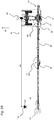
- an agricultural work machine 10 in the form of a self-propelled field sprayer and / or a fertilizer spreader (eg pneumatic fertilizer spreader) is shown in the perspective view of FIG Figure 1 , the side views of the Figures 2A & 2 B and the top views of Figures 3A & 3B emerged.
- the working machine 10 is each equipped as a self-propelled field sprayer with a motor unit 12 and a driver's cab 14 for an operator.
- the work machine 10 comprises, in particular, a system 100 as described herein.
- the work machine comprises a system 100 according to one of claims 1 to 14.
- work machine 10 is set up to carry out a method for determining a position of working elements as described herein, in particular to carry out a method according to at least one of the method claims 15 or 16.
- the work machine 10 comprises a chassis 16 carrying components of the work machine 10 with a running gear 18 and a frame structure 20 a storage container 22.
- the working machine 10 also comprises a rod 24, which is mounted on the chassis 16 so as to be adjustable in height relative to the chassis 16, in particular in the form of a distribution rod or spray rod.
- the linkage 24 is shown in a working position and extends over a large working width (e.g. 24 meters, 30 meters or more) transversely to the direction of travel FR.
- the linkage 24 is composed of a central part 26 and side parts 28 arranged pivotably on the left and right of the central part 26 by means of pivot axes 30.
- the side parts 28 are in turn composed of at least two segments which are pivotably arranged relative to one another by means of pivot axes 30.
- a plurality of working elements 32 (eg spray nozzles), which are arranged at a distance from one another and formed by distributing elements and which are operatively connected to the storage container 22, are attached to the rod 24 for distributing and discharging the agricultural material to be distributed Figures 2 & 3 only one so-called spray nozzle is shown.
- the working elements 32 can be controlled individually, in groups or as a whole by means of a data processing device 150. As from the Figures 2 & 3 As can be seen, the working elements 32 produce a distribution cone (eg spray cone) directed in the direction of a floor surface 50 for distributing the agricultural material to be distributed.
- the linkage 24 is mounted on the chassis 16 so that it can be adjusted in height relative to the chassis 16, an adjusting device 34 being provided to change the height of the linkage 24 relative to the chassis or an arable area 50 (e.g. soil, plants, or the like), which adjusting device 34
- an actuator for example hydraulic cylinder and / or pneumatic cylinder
- a Data processing device 150 wired and / or wirelessly signal-connected and / or signal-connectable.
- the height of the linkage 24 can be adjusted relative to the chassis 16 (see FIG Figure 2A & 2 B ), so that a first distance A1 of the linkage 24 changes with respect to an arable area 50, which in turn changes a second distance A2 between the working elements 32 with respect to the chassis 16, in particular with respect to a reference point 40, ie changes based on a height of the linkage 24 a second distance A2 of the working elements 32 from a reference point 40, in particular a distance in the direction of travel FR, this change also being influenced by the vehicle geometry and / or the linkage geometry and the change by means of the data processing device 150 based on the first distance A1 and the Vehicle geometry and / or linkage geometry can be calculated.
- the linkage 24 is mounted on a support structure 36, which support structure 36 is mounted in a height-adjustable manner with respect to the chassis 16 by means of a parallelogram.
- the linkage 24 can also be mounted on the support structure 36 so as to be rotatable about an axis of rotation running in the direction of travel FR.
- a vehicle geometry and a linkage geometry are again defined by means of the parallelogram, for example by the length of the links of the parallelogram and their articulation points on the chassis 16.
- the support structure 36 and the parallelogram can also be part of the chassis 16, respectively is.
- a data processing device 150 is set up to determine (e.g. calculate) a position of the working elements 32 relative to the reference point 40 on the basis of the altitude (e.g. a first distance A1), preferably taking into account the vehicle geometry and / or linkage geometry.
- a detection device 60 is provided to detect a height position of the linkage 24, ie to detect a first distance A1, the detection device 60 being formed in particular by a first sensor arrangement 62.
- the first sensor arrangement 62 here comprises at least one distance sensor (eg ultrasonic sensor) which is arranged on the linkage 24 and preferably measures downwards.
- the first sensor arrangement 62 is formed by an angle sensor which, for example, is coupled to the chassis 16 and the support structure 36 and in particular detects an elevation angle ⁇ , which, for example, is between the chassis 16 and the support structure 36, respectively between the chassis 16 and the parallelogram is available.
- a level of the linkage or a first distance A1 can be determined, for example by means of the data processing device.
- an adjusting device 34 is provided to adjust the height of the linkage 24 relative to the chassis 16 (i.e. relative to the arable land 50).
- the data processing device 150 is set up in particular to generate actuating signals for the actuating device 34.
- the setting device 34 is formed by an actuator in the form of a hydraulic cylinder, but two or more actuators would also be conceivable, as well as pneumatically and / or electrically operated actuators.
- the first sensor arrangement 62 is formed by a displacement sensor system and / or a pressure sensor system that is coupled to the actuating device 34 (e.g., functionally connected).
- the linkage 24 is composed of a central part 26 and side parts 28 which are pivotably arranged (eg mounted) on the left and right of the central part 26 by means of pivot axes 30 (for example, upright pivot axes) (see FIG Figure 3A & 3B ), whereby the side parts can again be composed of two or more segments or, in the exemplary embodiments, can be composed of two or more segments which can be pivotably mounted to one another by means of pivot axes 30 (e.g. upright or oriented parallel to the direction of travel FR).
- pivot axes 30 for example, upright pivot axes
- the linkage 24, in particular the side parts 28, performs pivoting movements (for example yawing and pitching movements and / or vibrations) with respect to the chassis 16, in particular with respect to the reference point 40 (see FIG Figure 3B ), so that a third distance A3 (eg horizontal distance) of the working elements 32 changes in relation to the reference point 40, in particular in relation to a plant 52.
- a fourth distance A4 (eg side distance) of the working elements 32 changes with respect to the reference point 40.
- the size of the pivot position can be defined, for example, by a pivot angle ⁇ of the side parts 28 with respect to the central part 26 and / or by a pivot angle ⁇ of the central part 26 with respect to the support structure 36. If the side parts are composed of two or more segments, a pivot angle ⁇ between two segments can also define a pivot position.
- a data processing device 150 is set up to use the pivot position (e.g. a pivot angle ⁇ ) to determine (e.g. calculate) a position of the working elements 32 relative to the reference point 40, preferably taking into account the vehicle geometry and / or linkage geometry (e.g. the boom width and / or the position of the working elements 32 on the boom 24 (eg on which segment, side part, middle part the working element 32 is attached)).
- a detection device 60 is provided to detect the pivot position in the direction of travel of the side parts 28 with respect to the central part 26 and / or of the central part 26 with respect to a support structure 36, the detection device 60 having a second sensor arrangement 64.
- the second sensor arrangement 64 is coupled (for example, functionally connected) by at least one angle sensor which is coupled to the side part 28 and the central part 26 and / or which is coupled to the central part 26 around the chassis 16 (or to the support structure 36) ) and / or which is coupled to two segments is formed.
- the pivot position of the linkage 24 with respect to the chassis 16, preferably the pivot position of the side parts 28 with respect to the central part 26, can be changed by means of an adjusting element 38.
- the data processing device 150 is set up in particular to generate actuating signals for the actuating element 38.
- the actuating element 38 is formed by an actuator in the form of a hydraulic cylinder, but two or more actuators would also be conceivable, as well as pneumatically and / or electrically operated actuators.
- the second sensor arrangement 64 is formed by a displacement sensor system and / or a pressure sensor system that is coupled to the actuating element 38 (e.g., functionally connected).
- the data processing device 150 is signal-connected and / or signal-connectable to a position determination system 74 (e.g. GPS system, RTK system or the like) and that the data processing device 150 is for this purpose according to the invention is set up to define a position of a reference point 40 on an arable area (eg floor area 50, usable area, or the like).
- a position determination system 74 e.g. GPS system, RTK system or the like
- the reference point 40 is defined by an antenna and / or a receiver of the position determination system 74, which means that the position of the reference point 40 on the arable land 50 is defined by means of the position determination system 74.
- the exact position of the working elements 32 on the arable land 50 can be defined, expediently, in particular, can be defined (eg calculated) by means of the data processing device 150.
- the data processing device 150 can be signal-connected and / or signal-connectable (e.g. also equipped) with a plant identification system.
- the plant identification system is set up to record status information (e.g. by means of a camera, sensors) of a crop of crops in an arable area 50.
- the status information can include, for example, a growth stage, clinical pictures, a number of useful plants and accompanying vegetation or the like.
- the data processing device 150 is set up to use a position of the work elements 32 and the status information recorded by the plant identification system to change the spread rate of agricultural distribution material and / or the mode of operation of individual, grouped or all work elements 32, expediently in particular Adapt status information.
- the Data processing device 150 with a plant identification system which is set up to define positions (e.g. by means of cameras, sensors, position determination systems, or the like) of plants 52 on an arable land, is signal-connected and / or signal-connectable, and that the data processing device 150 is set up, using a position of the work elements 32 relative to the reference point 40, and using the position of plants 52 defined by the plant identification system, in particular relative to the reference point 40, to change the application rate of agricultural distribution material and / or the mode of operation of individual, grouped or all work elements 32.
- the data processing device 150 is signal-connected and / or signal-connectable to a plant identification system, the plant identification system being set up to define a position of plants on an arable land 50 offline and / or to acquire status information of a plant population offline.
- offline in the context of the invention includes in particular that the plant identification system is not permanently connected to the work machine 10 or the linkage 24, i.e. that, for example, a camera or a sensor is not permanently attached to the work machine 10 or the linkage 24.
- the data processing device 150 is signal-connected and / or signal-connectable to a plant identification system, the plant identification system being assigned to or comprising a mobile terminal, a flying object 72 and / or a planning system 70.
Landscapes
- Life Sciences & Earth Sciences (AREA)
- Engineering & Computer Science (AREA)
- Insects & Arthropods (AREA)
- Pest Control & Pesticides (AREA)
- Wood Science & Technology (AREA)
- Zoology (AREA)
- Environmental Sciences (AREA)
- Lifting Devices For Agricultural Implements (AREA)
- Catching Or Destruction (AREA)
- Control Of Position, Course, Altitude, Or Attitude Of Moving Bodies (AREA)
Applications Claiming Priority (1)
| Application Number | Priority Date | Filing Date | Title |
|---|---|---|---|
| DE102020110367.0A DE102020110367A1 (de) | 2020-04-16 | 2020-04-16 | System für eine landwirtschaftliche Arbeitsmaschine, Verfahren zum Ermitteln einer Position von Arbeitselementen sowie landwirtschaftliche Arbeitsmaschine |
Publications (3)
| Publication Number | Publication Date |
|---|---|
| EP3895532A1 true EP3895532A1 (fr) | 2021-10-20 |
| EP3895532B1 EP3895532B1 (fr) | 2023-08-23 |
| EP3895532C0 EP3895532C0 (fr) | 2023-08-23 |
Family
ID=74666524
Family Applications (1)
| Application Number | Title | Priority Date | Filing Date |
|---|---|---|---|
| EP21157528.7A Active EP3895532B1 (fr) | 2020-04-16 | 2021-02-17 | Système pour une machine agricole de travail, procédé de détermination d'une position des éléments de travail, ainsi que machine agricole de travail |
Country Status (2)
| Country | Link |
|---|---|
| EP (1) | EP3895532B1 (fr) |
| DE (1) | DE102020110367A1 (fr) |
Families Citing this family (1)
| Publication number | Priority date | Publication date | Assignee | Title |
|---|---|---|---|---|
| US12532796B2 (en) * | 2024-02-26 | 2026-01-27 | Cnh Industrial America Llc | System and method for an agricultural machine |
Citations (5)
| Publication number | Priority date | Publication date | Assignee | Title |
|---|---|---|---|---|
| US20110153168A1 (en) * | 2009-12-18 | 2011-06-23 | Agco Corporation | Method to Enhance Performance of Sensor-Based Implement Height Control |
| WO2012032245A1 (fr) | 2010-09-10 | 2012-03-15 | Exel Industries | Ensemble de pulvérisation pour engin agricole à pilotage cartographique |
| EP3141114A1 (fr) * | 2015-09-08 | 2017-03-15 | Herbert Dammann GmbH | Système d'épandage et procédé d'épandage |
| EP3469898A1 (fr) * | 2017-09-27 | 2019-04-17 | HORSCH LEEB Application Systems GmbH | Machine d'épandage agricole et procédé de commande d'une telle machine d'épandage |
| US20190311198A1 (en) * | 2018-04-06 | 2019-10-10 | Cnh Industrial America Llc | Augmented reality for plant stand management |
Family Cites Families (10)
| Publication number | Priority date | Publication date | Assignee | Title |
|---|---|---|---|---|
| US8634993B2 (en) | 2003-03-20 | 2014-01-21 | Agjunction Llc | GNSS based control for dispensing material from vehicle |
| DE102007045846A1 (de) | 2007-09-26 | 2009-04-02 | Deere & Company, Moline | Landwirtschaftliche Maschine und Verfahren zur Positionsbestimmung |
| US20140180549A1 (en) | 2011-01-07 | 2014-06-26 | The Arizona Board Of Regents On Behalf Of The University Of Arizona | Automated machine for selective in situ manipulation of plants |
| AU2015265625B2 (en) | 2014-05-05 | 2020-10-08 | Deere And Company | Methods, systems, and devices relating to real-time object identification |
| US10786826B2 (en) | 2014-12-19 | 2020-09-29 | Deere & Company | Equalization of nozzle performance for sprayers |
| DE102017106342A1 (de) | 2017-03-24 | 2018-09-27 | Amazonen-Werke H. Dreyer Gmbh & Co. Kg | Verfahren zum adaptiven Regeln einer landwirtschaftlichen Maschine |
| DE102017114637A1 (de) | 2017-06-07 | 2018-12-13 | Amazonen-Werke H. Dreyer Gmbh & Co. Kg | Spritzeinrichtung für ein landwirtschaftliches Spritzgerät Durchflussmengenregelung |
| DE102017130845A1 (de) | 2017-12-21 | 2019-06-27 | Amazonen-Werke H. Dreyer Gmbh & Co. Kg | Steuer- und/oder Regelsystem, landwirtschaftliches Nutzfahrzeug und Verfahren zum Steuern und/oder Regeln eines landwirtschaftlichen Nutzfahrzeugs |
| AU2019305122B2 (en) | 2018-07-18 | 2024-08-01 | Precision Planting Llc | Systems and methods of working a field and determining a location of implements within a field |
| NL2022612B1 (en) | 2019-02-21 | 2020-08-31 | Exel Ind | Agricultural device and method for dispensing a liquid |
-
2020
- 2020-04-16 DE DE102020110367.0A patent/DE102020110367A1/de active Pending
-
2021
- 2021-02-17 EP EP21157528.7A patent/EP3895532B1/fr active Active
Patent Citations (5)
| Publication number | Priority date | Publication date | Assignee | Title |
|---|---|---|---|---|
| US20110153168A1 (en) * | 2009-12-18 | 2011-06-23 | Agco Corporation | Method to Enhance Performance of Sensor-Based Implement Height Control |
| WO2012032245A1 (fr) | 2010-09-10 | 2012-03-15 | Exel Industries | Ensemble de pulvérisation pour engin agricole à pilotage cartographique |
| EP3141114A1 (fr) * | 2015-09-08 | 2017-03-15 | Herbert Dammann GmbH | Système d'épandage et procédé d'épandage |
| EP3469898A1 (fr) * | 2017-09-27 | 2019-04-17 | HORSCH LEEB Application Systems GmbH | Machine d'épandage agricole et procédé de commande d'une telle machine d'épandage |
| US20190311198A1 (en) * | 2018-04-06 | 2019-10-10 | Cnh Industrial America Llc | Augmented reality for plant stand management |
Also Published As
| Publication number | Publication date |
|---|---|
| DE102020110367A1 (de) | 2021-10-21 |
| EP3895532B1 (fr) | 2023-08-23 |
| EP3895532C0 (fr) | 2023-08-23 |
Similar Documents
| Publication | Publication Date | Title |
|---|---|---|
| EP3141096B1 (fr) | Procede d'epandage de particules de semences ou de plantes dans un champ et machine correspondante | |
| EP4054305B1 (fr) | Machine agricole, de préférence pour le travail du sol et/ou le semis, et procédé de commande de la profondeur de travail d'une unité d'outil | |
| EP2622955B1 (fr) | Machine agricole dotée d'un système de réglage automatique d'un paramètre de travail et procédé correspondant | |
| EP3903549A1 (fr) | Machine de traitement du sol, de préférence herse-étrille agricole et procédé de réglage d'une force de précontrainte sur une herse-étrille | |
| DE102019129206B4 (de) | Selbstfahrende und/oder mittels Zugfahrzeug gezogene Landmaschine und Verfahren zur Steuerung und/oder Regelung einer Höhenlage eines Verteilgestänges einer derartigen Landmaschine | |
| WO2022033910A1 (fr) | Système et procédé pour une machine de distribution agricole, et machine de distribution agricole | |
| EP3732945B1 (fr) | Technique de la génération d'un profil de terrain à l'aide d'une machine agricole | |
| DE102020124792B4 (de) | Landwirtschaftliche Spritzvorrichtung, Verfahren zum Ausbringen von Spritzflüssigkeit und landwirtschaftliche Feldspritze | |
| EP3895531B1 (fr) | Système d'épandage agricole, procédé d'ajustement d'une quantité d'application, ainsi que machine d'épandage agricole | |
| EP3469898B1 (fr) | Machine d'épandage agricole et procédé de commande d'une telle machine d'épandage | |
| EP3895532B1 (fr) | Système pour une machine agricole de travail, procédé de détermination d'une position des éléments de travail, ainsi que machine agricole de travail | |
| DE102020106738A1 (de) | Kompensationssystem für eine Landmaschine, sowie Verteilmaschine und Verfahren zur Kompensation von Bodenunebenheiten für eine Landmaschine | |
| EP4014732B1 (fr) | Machine agricole à épandre et procédé de commande et/ou de régulation d'une machine agricole à épandre | |
| EP3466257B1 (fr) | Machine d'épandage agricole et procédé de commande d'une telle machine d'épandage | |
| DE102021101629A1 (de) | Autonomes landwirtschaftliches trägerfahrzeug und autonome landwirtschaftliche maschinenkombination | |
| WO2020043501A1 (fr) | Procédé de distribution d'un liquide de traitement sur une surface agricole | |
| DE102022109214A1 (de) | Landwirtschaftliche Verteilmaschine und Verfahren zum Ausbringen von landwirtschaftlichem Verteilgut | |
| EP4331356A1 (fr) | Machine de répartition agricole dotée d'une rampe de pulvérisation et procédé de commande de la position d'une telle rampe de pulvérisation | |
| EP4260701A1 (fr) | Machine de distribution agricole et procédé d'épandage de produit de distribution agricole | |
| EP4453682A1 (fr) | Système de configuration et procédé de mise en oeuvre d'une machine de travail agricole, et machine de travail agricole | |
| EP4230038A1 (fr) | Machine de répartition agricole et procédé de répartition précise en position d'agents actifs agricoles | |
| DE102021132471A9 (de) | Landwirtschaftliche Bodenbearbeitungseinrichtung mit Ausgabeeinrichtungen zur Ausgabe eines Ausgabemediums | |
| DE102021126258A1 (de) | Landwirtschaftliche Verteilmaschine, vorzugsweise eine Feldspritze oder ein pneumatischer Düngerstreuer | |
| DE102018131072A1 (de) | Steuerungs- und/oder Regelungssystem für ein Verteilgestänge eines pneumatischen Düngerstreuers, pneumatischer Düngerstreuer und Verfahren zur Steuerung- und/oder Regelung eines pneumatischen Düngerstreuers |
Legal Events
| Date | Code | Title | Description |
|---|---|---|---|
| PUAI | Public reference made under article 153(3) epc to a published international application that has entered the european phase |
Free format text: ORIGINAL CODE: 0009012 |
|
| STAA | Information on the status of an ep patent application or granted ep patent |
Free format text: STATUS: THE APPLICATION HAS BEEN PUBLISHED |
|
| AK | Designated contracting states |
Kind code of ref document: A1 Designated state(s): AL AT BE BG CH CY CZ DE DK EE ES FI FR GB GR HR HU IE IS IT LI LT LU LV MC MK MT NL NO PL PT RO RS SE SI SK SM TR |
|
| B565 | Issuance of search results under rule 164(2) epc |
Effective date: 20210914 |
|
| STAA | Information on the status of an ep patent application or granted ep patent |
Free format text: STATUS: REQUEST FOR EXAMINATION WAS MADE |
|
| 17P | Request for examination filed |
Effective date: 20220413 |
|
| RBV | Designated contracting states (corrected) |
Designated state(s): AL AT BE BG CH CY CZ DE DK EE ES FI FR GB GR HR HU IE IS IT LI LT LU LV MC MK MT NL NO PL PT RO RS SE SI SK SM TR |
|
| GRAP | Despatch of communication of intention to grant a patent |
Free format text: ORIGINAL CODE: EPIDOSNIGR1 |
|
| STAA | Information on the status of an ep patent application or granted ep patent |
Free format text: STATUS: GRANT OF PATENT IS INTENDED |
|
| INTG | Intention to grant announced |
Effective date: 20230426 |
|
| GRAS | Grant fee paid |
Free format text: ORIGINAL CODE: EPIDOSNIGR3 |
|
| GRAA | (expected) grant |
Free format text: ORIGINAL CODE: 0009210 |
|
| STAA | Information on the status of an ep patent application or granted ep patent |
Free format text: STATUS: THE PATENT HAS BEEN GRANTED |
|
| AK | Designated contracting states |
Kind code of ref document: B1 Designated state(s): AL AT BE BG CH CY CZ DE DK EE ES FI FR GB GR HR HU IE IS IT LI LT LU LV MC MK MT NL NO PL PT RO RS SE SI SK SM TR |
|
| REG | Reference to a national code |
Ref country code: GB Ref legal event code: FG4D Free format text: NOT ENGLISH |
|
| REG | Reference to a national code |
Ref country code: CH Ref legal event code: EP |
|
| REG | Reference to a national code |
Ref country code: IE Ref legal event code: FG4D Free format text: LANGUAGE OF EP DOCUMENT: GERMAN |
|
| REG | Reference to a national code |
Ref country code: DE Ref legal event code: R096 Ref document number: 502021001275 Country of ref document: DE |
|
| U01 | Request for unitary effect filed |
Effective date: 20230905 |
|
| U07 | Unitary effect registered |
Designated state(s): AT BE BG DE DK EE FI FR IT LT LU LV MT NL PT SE SI Effective date: 20230912 |
|
| PG25 | Lapsed in a contracting state [announced via postgrant information from national office to epo] |
Ref country code: GR Free format text: LAPSE BECAUSE OF FAILURE TO SUBMIT A TRANSLATION OF THE DESCRIPTION OR TO PAY THE FEE WITHIN THE PRESCRIBED TIME-LIMIT Effective date: 20231124 |
|
| PG25 | Lapsed in a contracting state [announced via postgrant information from national office to epo] |
Ref country code: IS Free format text: LAPSE BECAUSE OF FAILURE TO SUBMIT A TRANSLATION OF THE DESCRIPTION OR TO PAY THE FEE WITHIN THE PRESCRIBED TIME-LIMIT Effective date: 20231223 |
|
| PG25 | Lapsed in a contracting state [announced via postgrant information from national office to epo] |
Ref country code: RS Free format text: LAPSE BECAUSE OF FAILURE TO SUBMIT A TRANSLATION OF THE DESCRIPTION OR TO PAY THE FEE WITHIN THE PRESCRIBED TIME-LIMIT Effective date: 20230823 Ref country code: NO Free format text: LAPSE BECAUSE OF FAILURE TO SUBMIT A TRANSLATION OF THE DESCRIPTION OR TO PAY THE FEE WITHIN THE PRESCRIBED TIME-LIMIT Effective date: 20231123 Ref country code: IS Free format text: LAPSE BECAUSE OF FAILURE TO SUBMIT A TRANSLATION OF THE DESCRIPTION OR TO PAY THE FEE WITHIN THE PRESCRIBED TIME-LIMIT Effective date: 20231223 Ref country code: HR Free format text: LAPSE BECAUSE OF FAILURE TO SUBMIT A TRANSLATION OF THE DESCRIPTION OR TO PAY THE FEE WITHIN THE PRESCRIBED TIME-LIMIT Effective date: 20230823 Ref country code: GR Free format text: LAPSE BECAUSE OF FAILURE TO SUBMIT A TRANSLATION OF THE DESCRIPTION OR TO PAY THE FEE WITHIN THE PRESCRIBED TIME-LIMIT Effective date: 20231124 |
|
| PG25 | Lapsed in a contracting state [announced via postgrant information from national office to epo] |
Ref country code: PL Free format text: LAPSE BECAUSE OF FAILURE TO SUBMIT A TRANSLATION OF THE DESCRIPTION OR TO PAY THE FEE WITHIN THE PRESCRIBED TIME-LIMIT Effective date: 20230823 |
|
| U20 | Renewal fee for the european patent with unitary effect paid |
Year of fee payment: 4 Effective date: 20240215 |
|
| PG25 | Lapsed in a contracting state [announced via postgrant information from national office to epo] |
Ref country code: ES Free format text: LAPSE BECAUSE OF FAILURE TO SUBMIT A TRANSLATION OF THE DESCRIPTION OR TO PAY THE FEE WITHIN THE PRESCRIBED TIME-LIMIT Effective date: 20230823 |
|
| PG25 | Lapsed in a contracting state [announced via postgrant information from national office to epo] |
Ref country code: SM Free format text: LAPSE BECAUSE OF FAILURE TO SUBMIT A TRANSLATION OF THE DESCRIPTION OR TO PAY THE FEE WITHIN THE PRESCRIBED TIME-LIMIT Effective date: 20230823 Ref country code: RO Free format text: LAPSE BECAUSE OF FAILURE TO SUBMIT A TRANSLATION OF THE DESCRIPTION OR TO PAY THE FEE WITHIN THE PRESCRIBED TIME-LIMIT Effective date: 20230823 Ref country code: ES Free format text: LAPSE BECAUSE OF FAILURE TO SUBMIT A TRANSLATION OF THE DESCRIPTION OR TO PAY THE FEE WITHIN THE PRESCRIBED TIME-LIMIT Effective date: 20230823 Ref country code: CZ Free format text: LAPSE BECAUSE OF FAILURE TO SUBMIT A TRANSLATION OF THE DESCRIPTION OR TO PAY THE FEE WITHIN THE PRESCRIBED TIME-LIMIT Effective date: 20230823 Ref country code: SK Free format text: LAPSE BECAUSE OF FAILURE TO SUBMIT A TRANSLATION OF THE DESCRIPTION OR TO PAY THE FEE WITHIN THE PRESCRIBED TIME-LIMIT Effective date: 20230823 |
|
| REG | Reference to a national code |
Ref country code: DE Ref legal event code: R026 Ref document number: 502021001275 Country of ref document: DE |
|
| PLBI | Opposition filed |
Free format text: ORIGINAL CODE: 0009260 |
|
| PLAX | Notice of opposition and request to file observation + time limit sent |
Free format text: ORIGINAL CODE: EPIDOSNOBS2 |
|
| PLBP | Opposition withdrawn |
Free format text: ORIGINAL CODE: 0009264 |
|
| 26 | Opposition filed |
Opponent name: AMAZONEN-WERKE H. DREYER SE & CO. KG Effective date: 20240523 |
|
| PG25 | Lapsed in a contracting state [announced via postgrant information from national office to epo] |
Ref country code: MC Free format text: LAPSE BECAUSE OF FAILURE TO SUBMIT A TRANSLATION OF THE DESCRIPTION OR TO PAY THE FEE WITHIN THE PRESCRIBED TIME-LIMIT Effective date: 20230823 |
|
| REG | Reference to a national code |
Ref country code: CH Ref legal event code: PL |
|
| PLBB | Reply of patent proprietor to notice(s) of opposition received |
Free format text: ORIGINAL CODE: EPIDOSNOBS3 |
|
| PLBD | Termination of opposition procedure: decision despatched |
Free format text: ORIGINAL CODE: EPIDOSNOPC1 |
|
| REG | Reference to a national code |
Ref country code: DE Ref legal event code: R100 Ref document number: 502021001275 Country of ref document: DE |
|
| PG25 | Lapsed in a contracting state [announced via postgrant information from national office to epo] |
Ref country code: CH Free format text: LAPSE BECAUSE OF NON-PAYMENT OF DUE FEES Effective date: 20240229 |
|
| PG25 | Lapsed in a contracting state [announced via postgrant information from national office to epo] |
Ref country code: CH Free format text: LAPSE BECAUSE OF NON-PAYMENT OF DUE FEES Effective date: 20240229 |
|
| PLBM | Termination of opposition procedure: date of legal effect published |
Free format text: ORIGINAL CODE: 0009276 |
|
| PG25 | Lapsed in a contracting state [announced via postgrant information from national office to epo] |
Ref country code: IE Free format text: LAPSE BECAUSE OF NON-PAYMENT OF DUE FEES Effective date: 20240217 |
|
| PG25 | Lapsed in a contracting state [announced via postgrant information from national office to epo] |
Ref country code: IE Free format text: LAPSE BECAUSE OF NON-PAYMENT OF DUE FEES Effective date: 20240217 |
|
| 27C | Opposition proceedings terminated |
Effective date: 20241014 |
|
| U20 | Renewal fee for the european patent with unitary effect paid |
Year of fee payment: 5 Effective date: 20250224 |
|
| PG25 | Lapsed in a contracting state [announced via postgrant information from national office to epo] |
Ref country code: CY Free format text: LAPSE BECAUSE OF FAILURE TO SUBMIT A TRANSLATION OF THE DESCRIPTION OR TO PAY THE FEE WITHIN THE PRESCRIBED TIME-LIMIT; INVALID AB INITIO Effective date: 20210217 |
|
| PG25 | Lapsed in a contracting state [announced via postgrant information from national office to epo] |
Ref country code: HU Free format text: LAPSE BECAUSE OF FAILURE TO SUBMIT A TRANSLATION OF THE DESCRIPTION OR TO PAY THE FEE WITHIN THE PRESCRIBED TIME-LIMIT; INVALID AB INITIO Effective date: 20210217 |
|
| GBPC | Gb: european patent ceased through non-payment of renewal fee |
Effective date: 20250217 |
|
| PG25 | Lapsed in a contracting state [announced via postgrant information from national office to epo] |
Ref country code: TR Free format text: LAPSE BECAUSE OF FAILURE TO SUBMIT A TRANSLATION OF THE DESCRIPTION OR TO PAY THE FEE WITHIN THE PRESCRIBED TIME-LIMIT Effective date: 20230823 |
|
| PG25 | Lapsed in a contracting state [announced via postgrant information from national office to epo] |
Ref country code: GB Free format text: LAPSE BECAUSE OF NON-PAYMENT OF DUE FEES Effective date: 20250217 |
|
| U20 | Renewal fee for the european patent with unitary effect paid |
Year of fee payment: 6 Effective date: 20260224 |