EP3470879B1 - Capteur optoélectronique et procédé de détection sécurisée d'objets - Google Patents
Capteur optoélectronique et procédé de détection sécurisée d'objets Download PDFInfo
- Publication number
- EP3470879B1 EP3470879B1 EP17196669.0A EP17196669A EP3470879B1 EP 3470879 B1 EP3470879 B1 EP 3470879B1 EP 17196669 A EP17196669 A EP 17196669A EP 3470879 B1 EP3470879 B1 EP 3470879B1
- Authority
- EP
- European Patent Office
- Prior art keywords
- monitored
- fields
- monitoring
- sensor
- area
- Prior art date
- Legal status (The legal status is an assumption and is not a legal conclusion. Google has not performed a legal analysis and makes no representation as to the accuracy of the status listed.)
- Active
Links
Images


Classifications
-
- G—PHYSICS
- G01—MEASURING; TESTING
- G01S—RADIO DIRECTION-FINDING; RADIO NAVIGATION; DETERMINING DISTANCE OR VELOCITY BY USE OF RADIO WAVES; LOCATING OR PRESENCE-DETECTING BY USE OF THE REFLECTION OR RERADIATION OF RADIO WAVES; ANALOGOUS ARRANGEMENTS USING OTHER WAVES
- G01S17/00—Systems using the reflection or reradiation of electromagnetic waves other than radio waves, e.g. lidar systems
- G01S17/02—Systems using the reflection of electromagnetic waves other than radio waves
- G01S17/06—Systems determining position data of a target
- G01S17/42—Simultaneous measurement of distance and other co-ordinates
-
- G—PHYSICS
- G01—MEASURING; TESTING
- G01S—RADIO DIRECTION-FINDING; RADIO NAVIGATION; DETERMINING DISTANCE OR VELOCITY BY USE OF RADIO WAVES; LOCATING OR PRESENCE-DETECTING BY USE OF THE REFLECTION OR RERADIATION OF RADIO WAVES; ANALOGOUS ARRANGEMENTS USING OTHER WAVES
- G01S17/00—Systems using the reflection or reradiation of electromagnetic waves other than radio waves, e.g. lidar systems
- G01S17/88—Lidar systems specially adapted for specific applications
Definitions
- the invention relates to an optoelectronic sensor and a method for the reliable detection of objects in a monitoring area according to the preamble of claims 1 and 14, respectively.
- Such sensors are used, among other things, to protect machines. Conventionally, a protective field is monitored for this, which the operating personnel must not enter while the machine is in operation. If the sensor detects an impermissible protective field intervention, for example an operator's leg, it triggers an emergency stop of the machine.
- Sensors used in safety technology must work particularly reliably and therefore meet high safety requirements, for example the EN13849 standard for machine safety and the EN61496 device standard for electro-sensitive protective devices (ESPE). To meet these safety standards, a number of measures must be taken, such as safe electronic evaluation through redundant, diverse electronics or various function monitoring, especially monitoring the contamination of optical components including a front window.
- a task related to securing a machine is an access control, which limits the group of people who are in a certain area.
- very different security requirements are conceivable, ranging from simple counting at airports, for example, to strict access restrictions for very specific operators. Especially for the latter case, specially secured doors are often used.
- the door has been opened in compliance with the security procedure, there is no control to determine whether it actually is only one person passes through. Accordingly, the number of people in the secured area is also unknown.
- LOTO procedure lock out, tag out
- a machine in the secured area is additionally secured against unauthorized switching on.
- LOTO procedure lock out, tag out
- a real entry lock which only allows one person access, is also known, but very complex and cumbersome in everyday life, for example unsuitable for access with a car.
- Laser scanners generally provide much more precise position information and are already often used in safety technology.
- a safety laser scanner is from DE 43 40 756 A1 known.
- a light beam generated by a laser periodically sweeps over a monitored area with the aid of a deflection unit.
- the light is reflected on objects in the monitored area and evaluated in the laser scanner.
- the angular position of the object is determined from the angular position of the deflection unit and the distance of the object from the laser scanner is also deduced from the time of flight using the speed of light.
- the location of an object in the monitoring area is recorded in two-dimensional polar coordinates.
- the third spatial coordinate can also be detected by a relative movement in the transverse direction, for example by a further degree of freedom of movement of the deflection unit in the laser scanner or by moving the object relative to the laser scanner.
- phase-based methods the transmitted light is modulated and the phase shift of the received compared to the transmitted light is evaluated.
- pulse-based methods the laser scanner measures the transit time until a transmitted light pulse is received again. In one example from the EP 2 469 296 B1 Known pulse averaging methods, a large number of individual pulses are sent out for a measurement and the received pulses are statistically evaluated.
- Laser scanners have recently also been available that evaluate several protective fields simultaneously. In principle, this fulfills the requirement, because the monitoring area can now be freely divided into protective fields monitored in parallel and the current position of the intervening object can be deduced from the identity of an injured protective field.
- sequence monitoring in which it is determined whether protective fields are entered in a certain order in order to understand a movement. This is used, for example, so that when a robot approaches, protective fields are violated in the correct sequence and then left again in the reverse order. Then the robot can only slow down as long as the person is nearby and then continue working straight away at full speed, instead of being stopped with an emergency stop as in the classic way, which would also involve a laborious restart.
- the EP 2 012 253 B1 discloses a combination of an RFID reader with a laser scanner, the latter being responsible for recognizing whether an object whose RFID tag has been read has moved in an expected manner through a reading gate with the RFID reader.
- the laser scanner monitors a sequence of fields into which an object should have entered in the correct order. But this laser scanner is not safe. No people are to be protected in the application, only incorrect readings of remote RFID tags are to be avoided. In addition, the monitoring is very rough, because the only thing that matters is the proximity of the object to the reading station and the direction of movement, which can be reliably determined with very few monitoring fields.
- the EP 1 835 306 A1 discloses an apparatus for detecting obstacles in the vicinity of a vehicle.
- a sensor sends out a light fan with a light-dark pattern, which triggers a corresponding light-dark pattern in the sensor when an object moves relative to the light fan and enables the object to be localized in the direction of movement by counting the transitions over time. It is proposed to extend it, with a second light-dark pattern of another Wavelength transversely to the first light-dark pattern to achieve a spatial resolution in two coordinates.
- a LIDAR device is proposed for detecting surrounding objects for a vehicle, in which a plurality of non-overlapping, preferably strip-shaped transmission areas are generated.
- Sequential control can be used to differentiate in which transmission area an object is located.
- strip-shaped reception areas are additionally arranged orthogonally to the strip-shaped transmission areas.
- An automatic door system with a sensor is off D. Nishida et al., "Development of Intelligent Automatic Door System", IEEE International Conference on Robotics & Automation (ICRA), May 31 - June 7, 2014, Hong Kong, China .
- This object is achieved by an optoelectronic sensor and a method for the reliable detection of objects in a monitoring area according to claims 1 and 14, respectively.
- the sensor is able to reliably detect objects.
- the received light from the monitoring area is evaluated in order to monitor a first number of monitoring fields simultaneously.
- Monitoring fields are In particular, freely configured sub-areas of the monitoring area in accordance with the protective fields explained in the introduction, whose violation, however, unlike conventionally does not necessarily lead directly to a safety-related reaction.
- the simultaneous monitoring ensures that the monitoring field in which an object is located is reliably recorded, which would classically be referred to as a protective field violation.
- an object is an impermissible object, because it is possible to ignore or hide certain objects, for example because they are too small, only appear very briefly, or because they are known and permitted objects.
- the invention is based on the basic idea of allowing monitoring fields to at least partially overlap. From the point of view of the conventional safety function, this initially seems pointless, because it is sufficient once it has been recognized whether an object is in a dangerous position.
- the overlap results in a second number of overlap segments, the second number being greater than the first number, that is to say there are more and in particular significantly more overlap segments than fields of overlap.
- the overlap segments are defined by which overlap fields overlap there, so that the same monitoring fields overlap within a monitoring segment, while this changes to another monitoring segment with regard to at least one monitoring field, i.e. at least one overlap field is added, omitted or changed.
- each monitoring segment has a kind of fingerprint of the monitoring fields that overlap there, whereby the fingerprint can be imagined as a binary vector, for example. Its dimension corresponds to the first number, and its binary entries each contain a one for monitoring fields that overlap with the monitoring segment, and zeros otherwise. At least one entry of this fingerprint varies from monitoring segment to monitoring segment.
- the detection is safe preferably in the sense of machine safety, in particular according to the standards mentioned in the introduction.
- this does not necessarily mean that the sensor is used in a safety application.
- the configuration of the monitoring fields does not offer standard-compliant security, or that the application is only aimed at observation or, for example, protection in the sense of theft protection, not protection against the risk of injury.
- the invention has the advantage that the number of fields that can be monitored simultaneously is effectively increased from the first number actually provided on the hardware side to the second number. This enables a more precise position determination, but also information about a movement or an object size, which can be used to safely slow down a robot or machine or to relocate a work step to an area that is further away from the object engagement and thus no person endangered. This is just one example of a multitude of conceivable simple solutions for applications that benefit from the improved information and avoid downtimes of the robot or machine as far as possible.
- the configuration and evaluation of monitoring fields or monitoring segments is much easier to handle and program than raw information, for example in the form of distance and angle.
- a detected object is assigned to a monitoring segment based on the monitoring fields in which an object is recognized.
- the surveillance segments can be defined by a fingerprint, i.e. a binary vector that codes which monitoring fields monitor there. Accordingly, the result of the simultaneous evaluation of monitoring fields can be understood as a binary vector, in which monitoring segment an object intervention is detected. A comparison of the binary vectors shows the monitoring segment concerned.
- this is only a non-limiting example of how the assignment to a monitoring segment can be implemented.
- violations of the monitoring fields are evaluated in a first step in order to find the monitoring segment concerned. This can then be followed by a safety-related reaction such as a switch-off signal, with the monitoring segment then functioning as a protective field.
- a safety-related reaction such as a switch-off signal
- other evaluations are also conceivable which utilize the information about the object intervention that is recorded with improved resolution.
- a sequence of monitoring segments to which a detected object is assigned is preferably evaluated.
- the sequence or succession of monitoring segments in which an object is detected provides information about the path of an object Object in particular in the immediate past, specifically because of the increased second number of monitoring segments compared to the first number of monitoring fields with finer resolution. This enables a reaction, for example, depending on the direction of movement and speed, but also a prediction of the movement of a person in the vicinity of a source of danger to be secured and thus the planning of appropriate measures to protect it, preferably an adjustment that only requires a shutdown in rare emergencies.
- a movement of the object is advantageously monitored.
- the refined resolution by means of monitoring segments enables object tracking.
- An application example is the passage control by monitoring the movements at a passage.
- a passage is, for example, a passage area created by lateral boundaries, a door or the like.
- the sensor monitors when people move from one side to the other of the passage and preferably counts these events at the same time.
- the door and its position or opening status can also be monitored.
- the sensor according to the invention Because of the sensor according to the invention, it is always known whether someone is entering the secured area and preferably also how many people are there, or an overview is created of where people are in a larger monitored area. It is also conceivable to detect other objects, for example cars carried with people or the like. This is achieved in a very simple and inexpensive manner with the sensor according to the invention. Special organizational measures, access procedures or complex locks are not required for this.
- the sensor preferably has a safe output for outputting information about objects in monitoring fields.
- a conventional safety sensor often only supplies a binary switch-off signal. According to this preferred embodiment it is provided to output the information about the monitoring fields in which objects were detected, preferably for all monitoring fields monitored simultaneously.
- a violation of a monitoring field is only a safe output variable that is processed further, but not directly as is conventional with protective fields leads to a safety-related reaction.
- the result of further evaluations can be such a safety-related reaction.
- the evaluation unit is preferably implemented at least partially in a safety controller that is connected to the safe output via a safe interface.
- the sensor according to the invention is an arrangement of the actual sensor and an extension of its connections and evaluation capacity in the form of the safety controller.
- the sensor determines internally in which monitoring fields there are objects. This includes the actual measuring process, for example a time-of-flight measurement of a laser scanner. Further evaluation is carried out in the safety control based on the information output, for example a binary vector with one entry for each monitoring field.
- the information output for example a binary vector with one entry for each monitoring field.
- other subdivisions are also conceivable, for example that the finer evaluation of the monitoring segments in which objects are also carried out internally.
- a split evaluation with a safety controller a purely internal evaluation is also conceivable.
- the sensor is preferably designed as a laser scanner with a light transmitter for emitting a light signal and a deflection unit for periodically deflecting the light signal in the monitoring area.
- This is a sensor that is often used in security technology and has a large monitoring area that can be flexibly subdivided into monitoring fields and monitoring segments.
- Laser scanners of any known type come into consideration, in particular those with a deflection unit in the form of a rotating mirror or a rotating scanning head.
- the evaluation unit is preferably designed for a distance measurement with a time-of-flight method, with all known possibilities such as a pulse, a phase or a pulse averaging method also coming into consideration here.
- a camera in particular a 3D camera, and within certain limits also a light grid are conceivable as the sensor according to the invention, especially if it offers appropriate degrees of freedom as a scanning light grid with a distance measurement to define monitoring fields.
- the monitoring area is preferably described by two coordinates, a first group of monitoring fields the monitoring area with respect to the first coordinate and a second group of monitoring fields with respect to the second coordinate.
- the monitoring fields have a geometry that means that one group each covers the monitoring area in the assigned coordinate. However, gaps are conceivable and will be discussed later.
- the monitoring fields preferably have the same properties as one another.
- the groups of monitoring fields selected in this way mean that with a first group of n monitoring fields and a second group of m monitoring fields, i.e. a first number n + m, a total of a second number of up to n * m monitoring segments can be distinguished, depending on concrete design with gaps and a few more.
- the monitoring area does not necessarily mean the maximum viewing area, but rather a relevant sub-area selected within it.
- the first group preferably has strips or rectangles along the first coordinate and the second group has strips or rectangles along the second coordinate.
- the stripes or rectangles are preferably perpendicular to one another, so that a check pattern is formed, the boxes of which are the monitoring segments, but stripes at a different angle with correspondingly distorted boxes are also possible.
- the first group advantageously has circles or circular rings and the second group has circular sectors.
- the circles or circular rings subdivide a radial coordinate, the circular sectors or slices of pie an angular coordinate. This means that these monitoring fields are, as it were, adapted to the natural polar coordinates of a laser scanner, although it was explained in the introduction that the scan data itself is not available externally and that even if future laser scanners reliably provide this information, their safe direct evaluation is pronounced without using the established protective field monitoring would be laborious.
- the circular rings often do not encompass 360 ° because the viewing angle of available safe laser scanners is only slightly more than 180 °.
- the circles or circular rings of the first group can only be sectors of a circle which, in contrast to the monitoring fields of the second group, do not divide the angular coordinates. Rather, the circular rings individually cover the relevant viewing angle range, with the exception of the possible gaps still to be explained.
- the monitoring fields of a group are preferably each directly adjacent to one another. This subdivision is particularly intuitive. As an example, monitoring fields are located directly next to each other. In another of numerous examples, the i-th monitoring field in each case can be completely covered by the i + 1-th monitoring field, which in each case still adds a non-overlapping edge. This means that the same monitoring segments can be distinguished; only other fingerprints have to be evaluated. The distinction is of particular importance for safety technology, because under certain circumstances only the second example is permitted. In fact, in some standards there is a requirement that a protective field may only be directly connected to the observation source, i.e. that each protective field must also contain the line of sight to the sensor. Otherwise, shadows from areas that are not monitored could lead to errors.
- each point is monitored by a plurality of protective fields, so that it is sufficient if one of them meets the line-of-sight condition.
- the invention is not limited to applications in which this requirement applies.
- the monitoring fields of the first group preferably subdivide the monitoring area with regard to the first coordinate and / or the monitoring fields of the second group subdivide the monitoring area with regard to the second coordinate only up to at least one gap.
- This gap mentioned several times, is, so to speak, an additional passive monitoring field and increases the number of possible monitoring segments without additional effort.
- the information is used that none of the monitoring fields of a group is responding and consequently the object must be in the gap. This of course presupposes that only monitoring fields of the first group or the second group have a gap in the same position, otherwise it becomes a real gap in which there is no monitoring at all.
- a further monitoring field is preferably provided which covers half of the monitoring area.
- the second number can thus be doubled by dividing monitoring segments and distinguishing the partial monitoring segments according to whether or not they overlap with the further monitoring field.
- Half only needs to be reached approximately exactly; only a significant deviation leads to the advantage being significantly less than doubling.
- half does not necessarily relate to the area of the Monitoring area, but preferably to one of the two coordinates.
- the further monitoring field thus includes, for example, approximately half the radius to be monitored or approximately half the relevant viewing angle.
- Monitoring fields of a group are preferably nested one above the other, so that an inner monitoring field in each case completely overlaps with a next monitoring field and the next monitoring field protrudes at both edges with respect to the assigned coordinate.
- the nested arrangement is an example of a design of monitoring fields in which a doubling of the monitoring segments is possible with the additional monitoring field discussed in the previous paragraph.
- the invention relates to an improved object detection with a safe optoelectronic sensor. It is described below using specific embodiments with a safe laser scanner. However, this should not be understood in a limiting sense, because other optoelectronic sensors are also able to define protective or monitoring fields and safely detect objects in them.
- cameras in particular 3D cameras, for example based on the time-of-flight or stereo principle and, within limits, also light grids are mentioned. The latter allow sufficiently flexible protective field configurations if they are designed to be probing, i.e. not only detect beam interruptions, but also measure the distance to the interrupting object.
- FIG. 1 shows a schematic sectional illustration through a laser scanner 10.
- the laser scanner 10 is preferably designed as a safety laser scanner by fulfilling the standards mentioned in the introduction and the measures required for this.
- a light transmitter 12 for example a laser, generates a light beam 14 which has individual light pulses for a pulse or pulse averaging method or whose amplitude is modulated for a phase method.
- the light beam 14 is directed into a monitoring area 18 via light deflection units 16a-b and remitted there by an object that may be present.
- the reflected light 20 returns to the laser scanner 10 and is detected there via the deflection unit 16b and by means of receiving optics 22 by a light receiver 24, for example a photodiode.
- the deflection unit 16b is designed here as a rotating mirror which rotates continuously by driving a motor 26.
- the light beam 14 generated by the light transmitter 12 thus sweeps over the monitoring area 18 generated by the rotational movement Figure 1
- a wide variety of other designs are known for laser scanners, for example with a biaxial instead of a coaxial arrangement of light transmitter 12 and light receiver 24 or a rotating measuring head that includes light transmitter 12 and / or light receiver 24 or is coupled by light guides, as well as with several measuring modules or additional mobility to scan a three-dimensional space.
- the respective angular position of the deflection unit 16b is detected by an encoder 28. If a reflected light signal 20 received by the light receiver 24 is received from the monitoring area 18, the angular position of the object in the monitoring area 18 can be deduced from the angular position of the deflection unit 16b by means of the encoder 28.
- the transit time of the individual laser light pulses from their transmission to reception after reflection on the object in the monitoring area 18 is determined, or the phase shift between transmitted and received light is determined.
- the distance of the object from the laser scanner 10 is deduced from the resulting time of flight using the speed of light.
- This evaluation takes place in an evaluation unit 30, which is connected to the light transmitter 12, the light receiver 24, the motor 26 and the encoder 28 for this purpose.
- Two-dimensional polar coordinates of all objects in the monitored area 18 are now available via the angle and the distance. All of the functional components mentioned are arranged in a housing 32 which has a front panel 34 in the area of the light exit and light entry.
- the evaluation unit 30 is able to compare the position of the detected objects with monitoring fields, that is to say partial areas of the monitoring area 18, the geometry of which is specified or configured for the evaluation unit 30 by corresponding parameters.
- the evaluation unit 30 thus detects whether an impermissible object is located in the respective monitoring field.
- the monitoring fields are monitored simultaneously, whereby simultaneous is to be understood here as a counter-term to conventionally customary switchable protective fields.
- the evaluation of the object position with respect to the monitoring fields can be carried out in parallel for this purpose, but it is sufficient if the result is available within the response time of the laser scanner even with no or only with partial parallel evaluation.
- the term protective field would be common for the monitoring field. If an object is detected in a protective field, or if the protective field is violated, a safety-related shutdown (OSSD, Output Signal Switching Device) takes place. As a result, for example, an emergency stop of a machine connected and monitored by the laser scanner 10 is triggered or a vehicle on which the laser scanner 10 is mounted is braked.
- OSD Output Signal Switching Device
- the safe evaluation according to the invention of the monitoring fields as such can be the same as for a protective field.
- the detection of an object in a monitoring field does not yet immediately lead to a safety-related reaction, although it is conceivable to configure at least some of the monitoring fields as a protection field in this sense as well.
- the object intervention is preferably localized and analyzed even more precisely based on monitoring fields in which an object was detected. The end result can then again be a safety-related reaction, but it is also conceivable to initially only collect information, for example about the position, movement, direction of movement or speed of an object.
- the further evaluations of monitoring fields can in principle be carried out in the evaluation unit 30.
- at least some of the evaluations preferably take place outside the laser scanner 10.
- An advantageous division of tasks is that the internal evaluation unit 30 carries out the angle and distance measurements and evaluates the monitoring fields in which an object is detected. These data are then output via a safe output 36, which is, for example, an EFI interface (enhanced function interface).
- the laser scanner 10 itself is therefore a safe laser scanner with simultaneous monitoring of several monitoring fields.
- its output data is a binary vector with a length corresponding to the number of monitored fields evaluated, the entry of which is set to one wherever an object was detected in a monitored field.
- the corresponding information can also be provided in any other specific output format.
- FIG. 2 shows an arrangement of a laser scanner 10 and a safety controller 38 which is connected to the safe output 36.
- the safety controller 38 In a preferred embodiment, it receives the respective information about the monitoring fields in which an object is detected. The further evaluation is then implemented as safety logic in the safety controller 38. As a possible result of the evaluation, a safety-related signal can be output to a monitored machine or a robot via one of the outputs of the safety controller 38. The machine or robot then slows down or switches to work steps that detected objects cannot endanger, and only if necessary it is safely switched off in order to achieve high overall availability and productivity.
- Figure 3 shows a first embodiment of a configuration of at least partially overlapping monitoring fields 40, with which the spatial resolution of the detection of an object intrusion can be significantly improved. For this purpose, two groups of monitoring fields 40 are formed.
- a left first group comprises several concentric circular or ring-shaped monitoring fields 40, which are numbered 1 ... 4.
- the circles or rings divide the available radius from the center to the safe range. They are not complete because a safe laser scanner 10 is usually not designed for 360 ° monitoring, although this is not excluded in principle.
- the angle shown is only an example, angles of the order of magnitude of 270 ° and more can also be achieved with available devices.
- the number and width of the circles or rings are only exemplary; in particular, rings with different thicknesses are also conceivable.
- the representation of the circular or ring-shaped monitoring fields 1 ... 4 in Figure 3 understand in two ways, and this is intended to introduce two embodiments at the same time.
- they can be concentric circles with a growing radius
- circular rings with outer circular rings each directly adjoining the next inner circular ring. Both are equivalent for the subdivision and recording to be explained.
- a protective field must also contain the lines of sight to all points within the protective field so that any shading object is part of the protective field. This condition is only fulfilled for circles, but not for circular rings. However, that does not mean that there are not also applications for a configuration with circular rings.
- a middle, second group has several monitoring fields in the form of sectors of a circle or pie pieces, which are designated A ... D.
- the circular sectors divide the monitored viewing angle. Again, the number and width are only exemplary and, in particular, an uneven division of the angle with circular sectors of different sizes is possible.
- the monitoring fields 40 in the form of circular rings on the one hand and circular sectors on the other hand each cover the monitoring area 18, so there is even a complete overlap here.
- each location of the monitoring area 18 is monitored twice, namely once with a circular ring and once with a circular sector.
- a large number of monitoring segments 42 are created, each of which is defined by which circle or circular ring and which circular sector overlap there.
- a monitoring segment 3C is highlighted as an example where the circular ring 3 and the circular sector C overlap. If the group dividing the radius on the left is not defined by circular rings but concentric circles of increasing radius, the circular ring 3 can also be identified, namely by the fact that the circles 3 and 4 cover the object and the circles 1 and 2 do not. In contrast to this, only circle 4 would react in circular ring 4.
- the evaluation unit 30 of the laser scanner 10 simultaneously monitors the eight monitoring fields 40, namely the four circular rings 1..4 and the four circular sectors A ... D.
- An object detection in a monitoring field 40 does not lead directly to a safety-related reaction. Instead, the evaluation unit 30 itself or an external evaluation such as the safety controller 38 uses the information about the monitoring fields 40 in which an object is detected in order to find the monitoring segment 42 concerned. In the example of the monitoring segment 3C, an object would be detected both in the circular ring 3 and in the circular sector C. This results in a significantly higher number of sixteen effectively monitored monitoring segments 42 compared to the originally only eight monitored fields 40 evaluated simultaneously.
- the measure to be taken is then determined, namely whether a movement is (further) followed, a monitored machine is slowed down or initiated into non-dangerous work steps at a sufficient distance from the object intervention or whether a safety-related shutdown is required.
- n and m are divided into two groups, each of which is responsible for a coordinate as in Figure 3 for radius or angle, from the n + m monitoring fields n * m monitoring segments.
- the geometry of the monitoring fields 40 according to Figure 3 with circular rings and circular sectors is particularly well adapted to a laser scanner 10, but other geometric shapes are also conceivable.
- FIG. 4 shows another example.
- the monitoring fields 1 ... 5 of the first group are vertical stripes on the left
- the monitoring fields a..e of the second group are horizontal stripes in the middle. This results in the overlay on the right-hand side as in a checkered pattern, rectangular or square monitoring segments 42.
- staggered overlapping rectangles can be monitored, which may also be positioned at an angle or combined with circular sectors.
- the first group would then be formed from the monitoring fields 1, 1 + 2, 1 + 2 + 3, 1 + 2 + 3 + 4 and 1 + 2 + 3 + 4 + 5, the second group from c, b + c + d and a + b + c + d + e, the sensor 10 being assumed to be halfway up on the left.
- FIG. 3 illustrates the Figure 3 an example with polar coordinates and the Figure 4 an example with Cartesian coordinates.
- the same is possible by adapting the geometry of the monitoring fields 40 for any other coordinates.
- Each of the two groups subdivides one coordinate. Differentiate in the other coordinate the monitoring fields 40 of a group preferably do not overlap, although that would also be conceivable.
- the circles or circular rings each cover the same angular range and the sectors of the circle cover the same radius. Accordingly, in Figure 4 the stripes on the left are the same height and the stripes in the middle are the same width.
- the subdivision is complete and regular. There is therefore no area of the coordinate assigned to a group that is not covered by at least one monitoring field 40, and the monitoring fields 40 are of the same size, measured by their coordinate.
- the innermost circle or circular ring 1 is an exception, as it covers a larger radius area than the other circular rings 2..4.
- Another property in the examples of the Figures 3 and 4 is that the monitoring fields 40 within a group directly adjoin one another. At least if a line of sight is not allowed to be part of the monitoring field 40, it can be deviated from.
- the subdivision is not required to be complete or regular.
- An irregular division as in the example of the innermost circular ring 1 in Figure 3 is translated directly into correspondingly different monitoring segments 42.
- An incomplete subdivision which therefore has gaps, can either relate to an uninteresting part of the monitoring area 18 in which then no monitoring segments 42 are defined. However, gaps can even be found, as shown in the Figure 5 explained, the number of monitoring segments 42 with the number of monitoring fields 40 remaining the same.
- Figure 5 shows another exemplary configuration of monitoring fields 40, on the basis of which several advantageous modifications are to be explained, which are also possible individually and in no way only in this combination.
- the first group are left as in Figure 3 four circles or circular rings i..iv defined.
- a further outer circle or annulus which is virtual, so to speak, because there is only a gap there and no monitoring field 40 is defined and which will only be understood later.
- Circle sectors a..c are shown in the middle left. In contrast to Figure 3 The sectors of the circle a..c together do not cover the entire available viewing angle, but leave an angular area free on both sides outside. Corresponding, based on the angle coordinate, a gap analogous to the outermost circular ring, which is a gap in the radius coordinate and was explained in the previous paragraph.
- the circle sectors are also not next to each other as in Figure 3 , but are nested inside each other: The innermost circle sector a is completely overlapped by the next circle sector b, with additional margins on both sides, and these relationships can also be found between the circle sectors b and c.
- a further monitoring field LH is added to the two groups of monitoring fields 40 in the middle on the right, which covers the entire range and half the viewing angle, consequently half the monitoring area 18 in total.
- This configuration manages with four circles or circular rings, i..iv, three circular sectors a..c and a further monitoring field LH, that is to say a total of eight monitoring fields 40.
- a further monitoring field LH that is to say a total of eight monitoring fields 40.
- the mode of operation is best understood on the basis of the detection of an object in specific monitoring segments 42.
- the procedure hardly differs from Figure 3 .
- a pair of a circular ring i..iv and a circular sector a..c that is characteristic of the respective monitoring segment 42 responds.
- the further monitoring segment LH can be used to distinguish whether the object intervention took place above in the circular sectors E..G or below in the circular sectors B..D, so that ultimately the angular resolution is doubled by the further monitoring segment LH.
- the further monitoring field LH differentiates between 5A..5D on the one hand and 5E..5H on the other hand.
- the monitoring segments 5A and 5H are special.
- both the circular rings i..iv and the circular sectors a..c have a gap. This can still be absorbed in the case of the monitoring segment 5A, because here the further monitoring field LH guarantees reliable object detection. An object that is only detected by the further monitoring field can thus be localized in the monitoring segment 5A.
- Figure 6 shows a further exemplary configuration of monitoring fields 40. While in Figure 5 the circular sectors are nested inside one another and the further monitoring field LH thereby doubles the angular resolution, the circular rings are nested here, and a differently designed further monitoring field L doubles the radial resolution. For the sake of simplicity of explanation, gaps are not provided here, but as in Figure 5 can be added in order to obtain even more monitoring segments 42.
- an inner circular ring 3 is provided, which is completely overlapped by the next circular ring 2, with the inside and outside protruding edge areas, and the same applies to the ratio of the circular ring 2 to the outer circular ring 1. This is, based on the radius, the equivalent of the angle-related nesting of the circle sectors a ... c in Figure 5 .
- the inner circular rings 2..3 leave areas to the sensor 10 in which the direct line of sight is not monitored by the same monitoring field 40, which could be impermissible in some security applications.
- the circle sectors a..d the Figure 6 correspond to the Figure 3 .
- the further monitoring field L covers all angles, but only half the radius of the maximum range.
- the additional monitoring field L allows a distinction to be made between inner and outer radius areas and thus doubles the radial resolution.
- Figure 7 shows that the just got too Figures 5 and 6
- the concepts explained are not only suitable for circular geometries, but also for a horizontal and vertical, quasi-Cartesian grid. While in other words the Figures 5 and 6 Extensions to Figure 3 represent concerns Figure 7 corresponding extensions of the Figure 4 .
- two groups of monitoring fields 40 are initially formed, namely horizontal monitoring fields 1 ... 5 and vertical monitoring fields a..c.
- the vertical monitoring fields a..c are analogous to the circular sectors a..c of the Figure 5 nested.
- the monitoring field 5 is also an area that is not monitored.
- another monitoring field L is defined, which covers the left half of the monitoring area 18.
- FIG. 7 So you can do the Figure 7 as a Cartesian counterpart to Figure 5 and, quite analogously, eight monitoring fields 40, namely a first group of four overlapping horizontal rectangles, a second group of three centered, nested vertical rectangles and an indicator field for a certain half of the monitoring area, here the left half, total 39 Monitoring segments 42 are formed.
- the monitoring segments between B1 and F4 are recognized because the respectively responsible horizontal and vertical monitoring fields 40 overlapping there recognize an object at the same time.
- the horizontal information results from the lack of recognition in the vertical monitoring fields 40, correspondingly in A5 to G5 the vertical information from the lack of recognition in the horizontal ones Monitoring fields 40.
- the monitoring segment H5 is not monitored, therefore there are 39 and not 40 monitoring segments 42.
- the resolution can be further improved by additional monitoring fields 40.
- Figure 8 shows an application example for the configuration according to Figure 7 for passage control.
- a passage could also be monitored by another configuration, including radial configurations according to FIG Figure 3 , 5 or 6 , but usually a rectangular geometry is better suited to a passage.
- the passage area is formed here by a mechanical delimitation 44, this not necessarily having to be the case, since there are also applications in which the passage is to be monitored in free or only partially limited areas.
- the sensor 10 is according to the configuration of Figure 7 mounted in the center, although this is also conceivable differently with other configurations of differing geometries and / or overlaps.
- One or more doors can be located in the passage or at its ends.
- the monitoring segments 42 advantageously extend somewhat beyond the passage area between the mechanical delimitation 44.
- the monitoring segments 42 can be used not only to determine their current position, but also to track their path, as indicated by footprints 48a-b. For this purpose, the sequence of monitoring segments 42 in which an object intrusion was detected is evaluated. This also makes it possible to distinguish whether it is a or as in Figure 8 Several people 46a-b are involved, because monitoring segments 42 are addressed at the same time, in which an individual could not be at the same point in time. The distinction is made easier if the mechanical delimitation 44 ensures a relatively narrow passage in which people only move one behind the other.
- the monitoring fields 40 can for example be arranged at the level of the legs, calves or feet of a person. Each step violates one or more monitoring segments 42. Steps show a specific pattern, for example that one step is to be expected shortly after the other, namely only a few monitoring segments 42 further horizontally and alternately somewhat closer to and somewhat further away from the sensor 10 in the vertical direction. It should be noted that an object in a monitoring segment 42 is closer to the sensor 10 and is located behind it Monitoring segments 42 shaded. This is not critical, however, because in the course of the movement each person 46a-b first approaches the sensor 10 and then moves away again. These different perspectives of the sensor 10 on the people 46a-b nevertheless allow each individual person 46a-b to be recorded.
- the senor 10 may still fail to reliably differentiate between persons 46a-b walking close behind one another. Then it is at least recognized that it is not just one person 46a-b, and an error message is issued, for example with the request to leave the passage to the entry side and to re-enter with a greater distance between the persons 46a-b.
- the sensor 10 can also monitor a door 50, which is shown with its opening circle.
- the door 50 In the closed state, the door 50 should be detected in the monitoring segments A1-A5.
- other monitoring segments 42 are swept over by the door 50, as can be seen from the opening circle. All monitoring segments B1-B5 will still be affected, but then only the upper monitoring segments C1 to C3, but not the lower monitoring segments C4-C5.
- D2 is hit, but D1 is not, and shortly afterwards the monitoring segments A1-A5, B1-B3 and C2 become free again with movement in D3, whereby a person 46 could be detected there behind the door 50.
- the door 50 covers the monitoring segments A5-D5, from which the open door position can be recognized. It is clear that the specific sequence of the monitoring segments 42 concerned depends on the respective door 50, its position and the configuration of the monitoring fields 40, which is only exemplary.
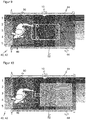
- FIG 9 shows again the passage according to Figure 8 with the configuration of monitoring fields 40 and monitoring segments 42 according to Figure 7 .
- the person 46 is carrying an object, in particular a cart 52, a pallet or the like.
- Such a carriage 52 can also be identified by evaluating the monitoring segments 42, in each of which an object is detected. For example, the four corners of the carriage 52 are suitable for this purpose. This can also be differentiated with the resolution given by the monitoring segments 42, such as a further example of another carriage 52 in FIG Figure 10 illustrated.
- the number of monitoring segments 42 can also be increased significantly by additional monitoring fields 40.
- Another possibility for improving the detection is to combine the detection of several sensors 10, for example one laser scanner each on both sides of the passage, in particular at different heights. This is particularly suitable for the case of a passage with a more complex geometry such as an L-shape, although this is also conceivable with only one laser scanner at the kink of the L-shape.
- the effective number of monitoring segments 42 compared to simultaneously monitored monitoring fields 40 is increased significantly from n + m to n * m by two groups each subdividing a coordinate. How with the Figures 5 and 6 explained, this can be increased even further by gaps or areas covered by only one group and / or a further overlap field which, with a clever design of the monitoring fields 40, halves the monitoring segments 42 again.
- the available simultaneously monitored monitoring fields 40 which are only available in limited numbers because of the evaluation effort, are optimally used for a finer resolution.
Landscapes
- Physics & Mathematics (AREA)
- Engineering & Computer Science (AREA)
- Electromagnetism (AREA)
- Computer Networks & Wireless Communication (AREA)
- General Physics & Mathematics (AREA)
- Radar, Positioning & Navigation (AREA)
- Remote Sensing (AREA)
- Optical Radar Systems And Details Thereof (AREA)
- Burglar Alarm Systems (AREA)
Claims (14)
- Capteur optoélectronique (10) pour la détection sécurisée d'objets dans une zone à surveiller (18), comportant un récepteur de lumière (24) pour générer un signal de réception à partir d'une lumière de réception (20) provenant de la zone à surveiller (18), et une unité d'évaluation (30) qui est réalisée pour surveiller simultanément un premier nombre de champs de surveillance (40), un champ de surveillance (40) étant une zone partielle configurée de la zone à surveiller (18), et pour constater à cet effet, sur la base du signal de réception, dans quel champ de surveillance (40) ou dans quels champs de surveillance (40) se trouve un objet, en comparant la position des objets détectés avec les champs de surveillance (40),
caractérisé en ce que
les champs de surveillance (40) se chevauchent au moins partiellement, de sorte qu'il se forme un second nombre supérieur au premier nombre de segments de surveillance (42), les segments de surveillance (42) se distinguant les uns des autres par le fait de savoir quels des champs de surveillance (40) s'y chevauchent, et en ce que
un objet détecté est affecté à un segment de surveillance (42) sur la base des champs de surveillance (40) dans lesquels un objet est reconnu. - Capteur (10) selon la revendication 1,
dans lequel une séquence de segments de surveillance (42) auxquels est affecté un objet détecté est évaluée. - Capteur (10) selon la revendication 2,
dans lequel un mouvement de l'objet est surveillé, en particulier un mouvement à travers un passage. - Capteur (10) selon l'une des revendications précédentes,
comprenant une sortie sécurisée (36) pour émettre des informations relatives à des objets dans des champs de surveillance (40). - Capteur (10) selon la revendication 4,
dans lequel l'unité d'évaluation (30) est au moins partiellement implémentée dans une commande de sécurité (38) qui est connectée à la sortie sécurisée (36) par une interface sécurisée. - Capteur (10) selon l'une des revendications précédentes,
réalisé sous la forme d'un scanner laser comportant un émetteur de lumière (12) pour émettre un signal lumineux (14) et une unité de déviation (16b) pour dévier périodiquement le signal lumineux (14) dans la zone à surveiller (18). - Capteur (10) selon l'une des revendications précédentes,
dans lequel la zone à surveiller (18) est décrite par deux coordonnées, et un premier groupe de champs de surveillance (40) subdivise la zone à surveiller (18) par rapport à la première coordonnée, et un second groupe de champs de surveillance (40) la subdivise par rapport à la seconde coordonnée. - Capteur (10) selon la revendication 7,
dans lequel le premier groupe comprend des bandes ou des rectangles le long de la première coordonnée, et le second groupe comprend des bandes ou des rectangles le long de la seconde coordonnée. - Capteur (10) selon la revendication 7,
dans lequel le premier groupe comprend des cercles ou des anneaux circulaires, et le second groupe comprend des secteurs de cercle. - Capteur (10) selon l'une des revendications 7 à 9,
dans lequel les champs de surveillance d'un groupe sont chacun immédiatement adjacents les uns aux autres. - Capteur (10) selon l'une des revendications 7 à 10,
dans lequel les champs de surveillance (40) du premier groupe subdivisent la zone à surveiller (18) par rapport à la première coordonnée, et/ou les champs de surveillance (40) du second groupe subdivisent la zone à surveiller (18) par rapport à la seconde coordonnée, exception faite seulement d'au moins une lacune. - Capteur (10) selon l'une des revendications 7 à 11,
dans lequel, en supplément aux champs de surveillance (40) des deux groupes, il est prévu un autre champ de surveillance (40, LH, L) qui recouvre la moitié de la zone à surveiller (18). - Capteur (10) selon l'une des revendications 7 à 12,
dans lequel les champs de surveillance (40) d'un groupe sont imbriqués les uns au-dessus des autres, de sorte qu'un champ de surveillance intérieur (40) chevauche complètement un champ de surveillance suivant respectif (40) et que le champ de surveillance suivant (40) dépasse sur les deux bords par rapport à la coordonnée affectée. - Procédé pour la détection sécurisée d'objets dans une zone à surveiller (18), dans lequel, des champs de surveillance (40) étant configurés comme des zones partielles de la zone à surveiller (18), on surveille simultanément un premier nombre de champs de surveillance (40), un champ de surveillance (40) étant une zone partielle configurée de la zone à surveiller (18), et, à cet effet, on constate sur la base d'un signal de réception d'une lumière provenant de la zone à surveiller (18) dans quel champ de surveillance (40) ou quels champs de surveillance (40) se trouve un objet, en comparant la position des objets détectés avec les champs de surveillance (40),
caractérisé en ce que
les champs de surveillance (40) se chevauchent au moins partiellement, de sorte qu'il se forme un second nombre supérieur au premier nombre de segments de surveillance (42), les segments de surveillance (42) se distinguant les uns des autres par le fait de savoir quels champs de surveillance (40) s'y chevauchent, et en ce que
un objet détecté est affecté à un segment de surveillance (42) sur la base des champs de surveillance (40) dans lesquels un objet est reconnu.
Priority Applications (1)
| Application Number | Priority Date | Filing Date | Title |
|---|---|---|---|
| EP17196669.0A EP3470879B1 (fr) | 2017-10-16 | 2017-10-16 | Capteur optoélectronique et procédé de détection sécurisée d'objets |
Applications Claiming Priority (1)
| Application Number | Priority Date | Filing Date | Title |
|---|---|---|---|
| EP17196669.0A EP3470879B1 (fr) | 2017-10-16 | 2017-10-16 | Capteur optoélectronique et procédé de détection sécurisée d'objets |
Publications (2)
| Publication Number | Publication Date |
|---|---|
| EP3470879A1 EP3470879A1 (fr) | 2019-04-17 |
| EP3470879B1 true EP3470879B1 (fr) | 2020-12-02 |
Family
ID=60164599
Family Applications (1)
| Application Number | Title | Priority Date | Filing Date |
|---|---|---|---|
| EP17196669.0A Active EP3470879B1 (fr) | 2017-10-16 | 2017-10-16 | Capteur optoélectronique et procédé de détection sécurisée d'objets |
Country Status (1)
| Country | Link |
|---|---|
| EP (1) | EP3470879B1 (fr) |
Families Citing this family (6)
| Publication number | Priority date | Publication date | Assignee | Title |
|---|---|---|---|---|
| EP3869240B1 (fr) | 2020-02-18 | 2025-01-29 | Leuze electronic GmbH + Co. KG | Agencement de capteurs et procédé de fonctionnement d'un agencement de capteurs |
| EP4431985B1 (fr) | 2023-03-15 | 2024-12-25 | Sick Ag | Suivi d'objet sécurisé d'un objet |
| EP4431787B1 (fr) | 2023-03-15 | 2025-01-22 | Sick Ag | Protection sans contact d'une machine |
| EP4516463B1 (fr) | 2023-08-29 | 2025-05-28 | Sick Ag | Protection sans contact sur une zone de coopération d'une machine |
| DE202024102711U1 (de) * | 2024-05-24 | 2025-08-28 | Leuze Electronic Gmbh + Co. Kg | Überwachungseinrichtung |
| EP4660513B1 (fr) | 2024-06-05 | 2026-04-08 | Sick Ag | Système de sécurité et procédé de sécurisation d'une machine |
Family Cites Families (5)
| Publication number | Priority date | Publication date | Assignee | Title |
|---|---|---|---|---|
| DE4340756C5 (de) | 1992-12-08 | 2006-08-10 | Sick Ag | Laserabstandsermittlungsvorrichtung |
| FR2898687B1 (fr) * | 2006-03-17 | 2008-05-09 | Valeo Vision Sa | Procede et dispositif de detection d'un obstacle au voisinage d'un vehicule en mouvement |
| DE102007030738A1 (de) | 2007-07-02 | 2009-01-08 | Sick Ag | Auslesen von Informationen mit optoelektronischem Sensor und RFID-Leser |
| DE102010061382B4 (de) | 2010-12-21 | 2019-02-14 | Sick Ag | Optoelektronischer Sensor und Verfahren zur Erfassung und Abstandsbestimmung von Objekten |
| DE102012101460A1 (de) * | 2012-02-23 | 2013-08-29 | Conti Temic Microelectronic Gmbh | Vorrichtung zur Erfassung von Umgebungsobjekten |
-
2017
- 2017-10-16 EP EP17196669.0A patent/EP3470879B1/fr active Active
Non-Patent Citations (1)
| Title |
|---|
| None * |
Also Published As
| Publication number | Publication date |
|---|---|
| EP3470879A1 (fr) | 2019-04-17 |
Similar Documents
| Publication | Publication Date | Title |
|---|---|---|
| EP3470879B1 (fr) | Capteur optoélectronique et procédé de détection sécurisée d'objets | |
| EP2315052B1 (fr) | Scanner de sécurité | |
| EP3709106B1 (fr) | Mise en sécurité d'une machine | |
| EP2413159B1 (fr) | Capteur optoélectronique mesurant l'éloignement pour le montage sur une ouverture de passage | |
| EP2989369B1 (fr) | Dispositif et procédé de sécurisation d'une machine travaillant de manière automatisée | |
| EP3611422B1 (fr) | Dispositif capteur et procédé de sécurisation d'une zone de surveillance | |
| DE4411448C5 (de) | Verfahren und Vorrichtung zur Kontrolle eines vorgegebenen Überwachungsbereichs | |
| DE102009034848B4 (de) | Optoelektronischer Sensor | |
| EP2282106B1 (fr) | Sécurité d'une zone accessible uniquement par une seule porte d'accès | |
| DE102012102236A1 (de) | Verfahren und Vorrichtung zum Absichern eines gefährlichen Arbeitsbereichs einer automatisiert arbeitenden Maschine | |
| EP3744482B1 (fr) | Fixation d'une pièce de machine mobile | |
| DE102019111640A1 (de) | Verfahren zum Absichern einer Gefahrenstelle | |
| EP3339715A1 (fr) | Système de protection d'accès | |
| EP3078985A1 (fr) | Capteur optoelectronique et procede de surveillance de transmission d'un disque frontal | |
| DE102018114552A1 (de) | Schutzvorrichtung und Verfahren zum Betreiben einer Schutzvorrichtung | |
| EP3425256A1 (fr) | Système de protection d'accès | |
| DE102016222245A1 (de) | Einrichtung und Verfahren zur Einwirkung auf Gegenstände | |
| EP2395372B1 (fr) | Scanner de sécurité | |
| EP4414143A1 (fr) | Procédé et capteur de distance sans contact pour sécuriser une machine | |
| EP4435313B1 (fr) | Système et procédé de surveillance d'une zone dangereuse d'une machine | |
| EP3150898B2 (fr) | Procede de commande automatisee d'un composant de machine | |
| DE102020129823A1 (de) | Visualisieren eines Schutzfeldes | |
| DE202020106491U1 (de) | Visualisieren eines Schutzfeldes | |
| DE202017103399U1 (de) | Zugangsabsicherungssystem | |
| EP4431787B1 (fr) | Protection sans contact d'une machine |
Legal Events
| Date | Code | Title | Description |
|---|---|---|---|
| PUAI | Public reference made under article 153(3) epc to a published international application that has entered the european phase |
Free format text: ORIGINAL CODE: 0009012 |
|
| STAA | Information on the status of an ep patent application or granted ep patent |
Free format text: STATUS: THE APPLICATION HAS BEEN PUBLISHED |
|
| AK | Designated contracting states |
Kind code of ref document: A1 Designated state(s): AL AT BE BG CH CY CZ DE DK EE ES FI FR GB GR HR HU IE IS IT LI LT LU LV MC MK MT NL NO PL PT RO RS SE SI SK SM TR |
|
| AX | Request for extension of the european patent |
Extension state: BA ME |
|
| STAA | Information on the status of an ep patent application or granted ep patent |
Free format text: STATUS: REQUEST FOR EXAMINATION WAS MADE |
|
| 17P | Request for examination filed |
Effective date: 20190827 |
|
| RBV | Designated contracting states (corrected) |
Designated state(s): AL AT BE BG CH CY CZ DE DK EE ES FI FR GB GR HR HU IE IS IT LI LT LU LV MC MK MT NL NO PL PT RO RS SE SI SK SM TR |
|
| STAA | Information on the status of an ep patent application or granted ep patent |
Free format text: STATUS: EXAMINATION IS IN PROGRESS |
|
| 17Q | First examination report despatched |
Effective date: 20191126 |
|
| RAP1 | Party data changed (applicant data changed or rights of an application transferred) |
Owner name: SICK AG |
|
| GRAP | Despatch of communication of intention to grant a patent |
Free format text: ORIGINAL CODE: EPIDOSNIGR1 |
|
| STAA | Information on the status of an ep patent application or granted ep patent |
Free format text: STATUS: GRANT OF PATENT IS INTENDED |
|
| INTG | Intention to grant announced |
Effective date: 20200814 |
|
| GRAS | Grant fee paid |
Free format text: ORIGINAL CODE: EPIDOSNIGR3 |
|
| GRAA | (expected) grant |
Free format text: ORIGINAL CODE: 0009210 |
|
| STAA | Information on the status of an ep patent application or granted ep patent |
Free format text: STATUS: THE PATENT HAS BEEN GRANTED |
|
| AK | Designated contracting states |
Kind code of ref document: B1 Designated state(s): AL AT BE BG CH CY CZ DE DK EE ES FI FR GB GR HR HU IE IS IT LI LT LU LV MC MK MT NL NO PL PT RO RS SE SI SK SM TR |
|
| REG | Reference to a national code |
Ref country code: GB Ref legal event code: FG4D Free format text: NOT ENGLISH |
|
| REG | Reference to a national code |
Ref country code: AT Ref legal event code: REF Ref document number: 1341543 Country of ref document: AT Kind code of ref document: T Effective date: 20201215 Ref country code: CH Ref legal event code: EP |
|
| REG | Reference to a national code |
Ref country code: DE Ref legal event code: R096 Ref document number: 502017008442 Country of ref document: DE |
|
| REG | Reference to a national code |
Ref country code: IE Ref legal event code: FG4D Free format text: LANGUAGE OF EP DOCUMENT: GERMAN |
|
| PG25 | Lapsed in a contracting state [announced via postgrant information from national office to epo] |
Ref country code: RS Free format text: LAPSE BECAUSE OF FAILURE TO SUBMIT A TRANSLATION OF THE DESCRIPTION OR TO PAY THE FEE WITHIN THE PRESCRIBED TIME-LIMIT Effective date: 20201202 Ref country code: NO Free format text: LAPSE BECAUSE OF FAILURE TO SUBMIT A TRANSLATION OF THE DESCRIPTION OR TO PAY THE FEE WITHIN THE PRESCRIBED TIME-LIMIT Effective date: 20210302 Ref country code: FI Free format text: LAPSE BECAUSE OF FAILURE TO SUBMIT A TRANSLATION OF THE DESCRIPTION OR TO PAY THE FEE WITHIN THE PRESCRIBED TIME-LIMIT Effective date: 20201202 Ref country code: GR Free format text: LAPSE BECAUSE OF FAILURE TO SUBMIT A TRANSLATION OF THE DESCRIPTION OR TO PAY THE FEE WITHIN THE PRESCRIBED TIME-LIMIT Effective date: 20210303 |
|
| REG | Reference to a national code |
Ref country code: NL Ref legal event code: MP Effective date: 20201202 |
|
| PG25 | Lapsed in a contracting state [announced via postgrant information from national office to epo] |
Ref country code: LV Free format text: LAPSE BECAUSE OF FAILURE TO SUBMIT A TRANSLATION OF THE DESCRIPTION OR TO PAY THE FEE WITHIN THE PRESCRIBED TIME-LIMIT Effective date: 20201202 Ref country code: PL Free format text: LAPSE BECAUSE OF FAILURE TO SUBMIT A TRANSLATION OF THE DESCRIPTION OR TO PAY THE FEE WITHIN THE PRESCRIBED TIME-LIMIT Effective date: 20201202 Ref country code: BG Free format text: LAPSE BECAUSE OF FAILURE TO SUBMIT A TRANSLATION OF THE DESCRIPTION OR TO PAY THE FEE WITHIN THE PRESCRIBED TIME-LIMIT Effective date: 20210302 Ref country code: SE Free format text: LAPSE BECAUSE OF FAILURE TO SUBMIT A TRANSLATION OF THE DESCRIPTION OR TO PAY THE FEE WITHIN THE PRESCRIBED TIME-LIMIT Effective date: 20201202 |
|
| PG25 | Lapsed in a contracting state [announced via postgrant information from national office to epo] |
Ref country code: NL Free format text: LAPSE BECAUSE OF FAILURE TO SUBMIT A TRANSLATION OF THE DESCRIPTION OR TO PAY THE FEE WITHIN THE PRESCRIBED TIME-LIMIT Effective date: 20201202 Ref country code: HR Free format text: LAPSE BECAUSE OF FAILURE TO SUBMIT A TRANSLATION OF THE DESCRIPTION OR TO PAY THE FEE WITHIN THE PRESCRIBED TIME-LIMIT Effective date: 20201202 |
|
| REG | Reference to a national code |
Ref country code: LT Ref legal event code: MG9D |
|
| PG25 | Lapsed in a contracting state [announced via postgrant information from national office to epo] |
Ref country code: SK Free format text: LAPSE BECAUSE OF FAILURE TO SUBMIT A TRANSLATION OF THE DESCRIPTION OR TO PAY THE FEE WITHIN THE PRESCRIBED TIME-LIMIT Effective date: 20201202 Ref country code: RO Free format text: LAPSE BECAUSE OF FAILURE TO SUBMIT A TRANSLATION OF THE DESCRIPTION OR TO PAY THE FEE WITHIN THE PRESCRIBED TIME-LIMIT Effective date: 20201202 Ref country code: PT Free format text: LAPSE BECAUSE OF FAILURE TO SUBMIT A TRANSLATION OF THE DESCRIPTION OR TO PAY THE FEE WITHIN THE PRESCRIBED TIME-LIMIT Effective date: 20210405 Ref country code: SM Free format text: LAPSE BECAUSE OF FAILURE TO SUBMIT A TRANSLATION OF THE DESCRIPTION OR TO PAY THE FEE WITHIN THE PRESCRIBED TIME-LIMIT Effective date: 20201202 Ref country code: LT Free format text: LAPSE BECAUSE OF FAILURE TO SUBMIT A TRANSLATION OF THE DESCRIPTION OR TO PAY THE FEE WITHIN THE PRESCRIBED TIME-LIMIT Effective date: 20201202 Ref country code: EE Free format text: LAPSE BECAUSE OF FAILURE TO SUBMIT A TRANSLATION OF THE DESCRIPTION OR TO PAY THE FEE WITHIN THE PRESCRIBED TIME-LIMIT Effective date: 20201202 Ref country code: CZ Free format text: LAPSE BECAUSE OF FAILURE TO SUBMIT A TRANSLATION OF THE DESCRIPTION OR TO PAY THE FEE WITHIN THE PRESCRIBED TIME-LIMIT Effective date: 20201202 |
|
| REG | Reference to a national code |
Ref country code: DE Ref legal event code: R097 Ref document number: 502017008442 Country of ref document: DE |
|
| PG25 | Lapsed in a contracting state [announced via postgrant information from national office to epo] |
Ref country code: IS Free format text: LAPSE BECAUSE OF FAILURE TO SUBMIT A TRANSLATION OF THE DESCRIPTION OR TO PAY THE FEE WITHIN THE PRESCRIBED TIME-LIMIT Effective date: 20210402 |
|
| PLBE | No opposition filed within time limit |
Free format text: ORIGINAL CODE: 0009261 |
|
| STAA | Information on the status of an ep patent application or granted ep patent |
Free format text: STATUS: NO OPPOSITION FILED WITHIN TIME LIMIT |
|
| PG25 | Lapsed in a contracting state [announced via postgrant information from national office to epo] |
Ref country code: AL Free format text: LAPSE BECAUSE OF FAILURE TO SUBMIT A TRANSLATION OF THE DESCRIPTION OR TO PAY THE FEE WITHIN THE PRESCRIBED TIME-LIMIT Effective date: 20201202 |
|
| 26N | No opposition filed |
Effective date: 20210903 |
|
| PG25 | Lapsed in a contracting state [announced via postgrant information from national office to epo] |
Ref country code: DK Free format text: LAPSE BECAUSE OF FAILURE TO SUBMIT A TRANSLATION OF THE DESCRIPTION OR TO PAY THE FEE WITHIN THE PRESCRIBED TIME-LIMIT Effective date: 20201202 Ref country code: SI Free format text: LAPSE BECAUSE OF FAILURE TO SUBMIT A TRANSLATION OF THE DESCRIPTION OR TO PAY THE FEE WITHIN THE PRESCRIBED TIME-LIMIT Effective date: 20201202 |
|
| PG25 | Lapsed in a contracting state [announced via postgrant information from national office to epo] |
Ref country code: ES Free format text: LAPSE BECAUSE OF FAILURE TO SUBMIT A TRANSLATION OF THE DESCRIPTION OR TO PAY THE FEE WITHIN THE PRESCRIBED TIME-LIMIT Effective date: 20201202 |
|
| REG | Reference to a national code |
Ref country code: CH Ref legal event code: PL |
|
| PG25 | Lapsed in a contracting state [announced via postgrant information from national office to epo] |
Ref country code: IS Free format text: LAPSE BECAUSE OF FAILURE TO SUBMIT A TRANSLATION OF THE DESCRIPTION OR TO PAY THE FEE WITHIN THE PRESCRIBED TIME-LIMIT Effective date: 20210402 |
|
| REG | Reference to a national code |
Ref country code: BE Ref legal event code: MM Effective date: 20211031 |
|
| PG25 | Lapsed in a contracting state [announced via postgrant information from national office to epo] |
Ref country code: MC Free format text: LAPSE BECAUSE OF FAILURE TO SUBMIT A TRANSLATION OF THE DESCRIPTION OR TO PAY THE FEE WITHIN THE PRESCRIBED TIME-LIMIT Effective date: 20201202 |
|
| PG25 | Lapsed in a contracting state [announced via postgrant information from national office to epo] |
Ref country code: LU Free format text: LAPSE BECAUSE OF NON-PAYMENT OF DUE FEES Effective date: 20211016 Ref country code: BE Free format text: LAPSE BECAUSE OF NON-PAYMENT OF DUE FEES Effective date: 20211031 |
|
| PG25 | Lapsed in a contracting state [announced via postgrant information from national office to epo] |
Ref country code: LI Free format text: LAPSE BECAUSE OF NON-PAYMENT OF DUE FEES Effective date: 20211031 Ref country code: CH Free format text: LAPSE BECAUSE OF NON-PAYMENT OF DUE FEES Effective date: 20211031 |
|
| PG25 | Lapsed in a contracting state [announced via postgrant information from national office to epo] |
Ref country code: IE Free format text: LAPSE BECAUSE OF NON-PAYMENT OF DUE FEES Effective date: 20211016 |
|
| PG25 | Lapsed in a contracting state [announced via postgrant information from national office to epo] |
Ref country code: CY Free format text: LAPSE BECAUSE OF FAILURE TO SUBMIT A TRANSLATION OF THE DESCRIPTION OR TO PAY THE FEE WITHIN THE PRESCRIBED TIME-LIMIT Effective date: 20201202 |
|
| PG25 | Lapsed in a contracting state [announced via postgrant information from national office to epo] |
Ref country code: HU Free format text: LAPSE BECAUSE OF FAILURE TO SUBMIT A TRANSLATION OF THE DESCRIPTION OR TO PAY THE FEE WITHIN THE PRESCRIBED TIME-LIMIT; INVALID AB INITIO Effective date: 20171016 |
|
| PG25 | Lapsed in a contracting state [announced via postgrant information from national office to epo] |
Ref country code: MK Free format text: LAPSE BECAUSE OF FAILURE TO SUBMIT A TRANSLATION OF THE DESCRIPTION OR TO PAY THE FEE WITHIN THE PRESCRIBED TIME-LIMIT Effective date: 20201202 |
|
| PG25 | Lapsed in a contracting state [announced via postgrant information from national office to epo] |
Ref country code: TR Free format text: LAPSE BECAUSE OF FAILURE TO SUBMIT A TRANSLATION OF THE DESCRIPTION OR TO PAY THE FEE WITHIN THE PRESCRIBED TIME-LIMIT Effective date: 20201202 |
|
| PG25 | Lapsed in a contracting state [announced via postgrant information from national office to epo] |
Ref country code: MT Free format text: LAPSE BECAUSE OF FAILURE TO SUBMIT A TRANSLATION OF THE DESCRIPTION OR TO PAY THE FEE WITHIN THE PRESCRIBED TIME-LIMIT Effective date: 20201202 |
|
| PGFP | Annual fee paid to national office [announced via postgrant information from national office to epo] |
Ref country code: DE Payment date: 20251020 Year of fee payment: 9 |
|
| PGFP | Annual fee paid to national office [announced via postgrant information from national office to epo] |
Ref country code: GB Payment date: 20251024 Year of fee payment: 9 |
|
| PGFP | Annual fee paid to national office [announced via postgrant information from national office to epo] |
Ref country code: AT Payment date: 20251021 Year of fee payment: 9 |
|
| PGFP | Annual fee paid to national office [announced via postgrant information from national office to epo] |
Ref country code: IT Payment date: 20251031 Year of fee payment: 9 |
|
| PGFP | Annual fee paid to national office [announced via postgrant information from national office to epo] |
Ref country code: FR Payment date: 20251024 Year of fee payment: 9 |