EP3477996A1 - Kommunikationsverfahren, netzwerkvorrichtung und endgerätevorrichtungen - Google Patents
Kommunikationsverfahren, netzwerkvorrichtung und endgerätevorrichtungen Download PDFInfo
- Publication number
- EP3477996A1 EP3477996A1 EP16908451.4A EP16908451A EP3477996A1 EP 3477996 A1 EP3477996 A1 EP 3477996A1 EP 16908451 A EP16908451 A EP 16908451A EP 3477996 A1 EP3477996 A1 EP 3477996A1
- Authority
- EP
- European Patent Office
- Prior art keywords
- communication link
- terminal device
- network device
- signal quality
- measurement data
- Prior art date
- Legal status (The legal status is an assumption and is not a legal conclusion. Google has not performed a legal analysis and makes no representation as to the accuracy of the status listed.)
- Granted
Links
Images



Classifications
-
- H—ELECTRICITY
- H04—ELECTRIC COMMUNICATION TECHNIQUE
- H04W—WIRELESS COMMUNICATION NETWORKS
- H04W24/00—Supervisory, monitoring or testing arrangements
- H04W24/02—Arrangements for optimising operational condition
-
- H—ELECTRICITY
- H04—ELECTRIC COMMUNICATION TECHNIQUE
- H04W—WIRELESS COMMUNICATION NETWORKS
- H04W40/00—Communication routing or communication path finding
- H04W40/02—Communication route or path selection, e.g. power-based or shortest path routing
- H04W40/04—Communication route or path selection, e.g. power-based or shortest path routing based on wireless node resources
- H04W40/10—Communication route or path selection, e.g. power-based or shortest path routing based on wireless node resources based on available power or energy
-
- H—ELECTRICITY
- H04—ELECTRIC COMMUNICATION TECHNIQUE
- H04W—WIRELESS COMMUNICATION NETWORKS
- H04W36/00—Hand-off or reselection arrangements
- H04W36/0005—Control or signalling for completing the hand-off
- H04W36/0055—Transmission or use of information for re-establishing the radio link
- H04W36/0069—Transmission or use of information for re-establishing the radio link in case of dual connectivity, e.g. decoupled uplink/downlink
- H04W36/00698—Transmission or use of information for re-establishing the radio link in case of dual connectivity, e.g. decoupled uplink/downlink using different RATs
-
- H—ELECTRICITY
- H04—ELECTRIC COMMUNICATION TECHNIQUE
- H04W—WIRELESS COMMUNICATION NETWORKS
- H04W36/00—Hand-off or reselection arrangements
- H04W36/03—Reselecting a link using a direct mode connection
-
- H—ELECTRICITY
- H04—ELECTRIC COMMUNICATION TECHNIQUE
- H04W—WIRELESS COMMUNICATION NETWORKS
- H04W36/00—Hand-off or reselection arrangements
- H04W36/16—Performing reselection for specific purposes
-
- H—ELECTRICITY
- H04—ELECTRIC COMMUNICATION TECHNIQUE
- H04W—WIRELESS COMMUNICATION NETWORKS
- H04W36/00—Hand-off or reselection arrangements
- H04W36/24—Reselection being triggered by specific parameters
- H04W36/30—Reselection being triggered by specific parameters by measured or perceived connection quality data
-
- H—ELECTRICITY
- H04—ELECTRIC COMMUNICATION TECHNIQUE
- H04W—WIRELESS COMMUNICATION NETWORKS
- H04W36/00—Hand-off or reselection arrangements
- H04W36/34—Reselection control
- H04W36/38—Reselection control by fixed network equipment
-
- H—ELECTRICITY
- H04—ELECTRIC COMMUNICATION TECHNIQUE
- H04W—WIRELESS COMMUNICATION NETWORKS
- H04W52/00—Power management, e.g. Transmission Power Control [TPC] or power classes
- H04W52/02—Power saving arrangements
- H04W52/0209—Power saving arrangements in terminal devices
- H04W52/0261—Power saving arrangements in terminal devices managing power supply demand, e.g. depending on battery level
-
- H—ELECTRICITY
- H04—ELECTRIC COMMUNICATION TECHNIQUE
- H04W—WIRELESS COMMUNICATION NETWORKS
- H04W76/00—Connection management
- H04W76/10—Connection setup
- H04W76/14—Direct-mode setup
-
- H—ELECTRICITY
- H04—ELECTRIC COMMUNICATION TECHNIQUE
- H04W—WIRELESS COMMUNICATION NETWORKS
- H04W88/00—Devices specially adapted for wireless communication networks, e.g. terminals, base stations or access point devices
- H04W88/02—Terminal devices
- H04W88/04—Terminal devices adapted for relaying to or from another terminal or user
-
- H—ELECTRICITY
- H04—ELECTRIC COMMUNICATION TECHNIQUE
- H04W—WIRELESS COMMUNICATION NETWORKS
- H04W84/00—Network topologies
- H04W84/18—Self-organising networks, e.g. ad-hoc networks or sensor networks
-
- Y—GENERAL TAGGING OF NEW TECHNOLOGICAL DEVELOPMENTS; GENERAL TAGGING OF CROSS-SECTIONAL TECHNOLOGIES SPANNING OVER SEVERAL SECTIONS OF THE IPC; TECHNICAL SUBJECTS COVERED BY FORMER USPC CROSS-REFERENCE ART COLLECTIONS [XRACs] AND DIGESTS
- Y02—TECHNOLOGIES OR APPLICATIONS FOR MITIGATION OR ADAPTATION AGAINST CLIMATE CHANGE
- Y02D—CLIMATE CHANGE MITIGATION TECHNOLOGIES IN INFORMATION AND COMMUNICATION TECHNOLOGIES [ICT], I.E. INFORMATION AND COMMUNICATION TECHNOLOGIES AIMING AT THE REDUCTION OF THEIR OWN ENERGY USE
- Y02D30/00—Reducing energy consumption in communication networks
- Y02D30/70—Reducing energy consumption in communication networks in wireless communication networks
Definitions
- the present invention relates to the communications field, and more specifically, to a communication method, a network device, and a terminal device.
- a terminal device communicates with a base station over an air interface (for example, a Uu interface). By using the base station, user data is forwarded to a destination node in a network or data from a network is forwarded to the terminal device.
- a device-to-device (Device-to-Device, D2D) communications technology is a technology for communication between terminals. Different from the existing cellular communications technology, in the D2D communications technology, terminal device data does not need to be transmitted through a base station, but is directly transmitted over an air interface (for example, a PC5 interface) between terminals.
- the D2D communications technology reduces dependence of communication between terminal devices on a network and reduces a forwarding latency and network load to some extent, and therefore is widely applied.
- the terminal device encounters the following scenario: When the terminal device has little electricity remained or the terminal device has a relatively weak electric energy capability, if the terminal device performs the communication at relatively high power, electricity (or electric energy) may be rapidly consumed and the communication is interrupted. Therefore, in the foregoing scenario, how to reduce power consumption of the terminal device to save electricity (or electric energy) of the terminal device becomes a problem that needs to be considered.
- This application provides a communication method, a network device, and a terminal device, which can reduce terminal device power consumption.
- this application provides a communication method, applied to a communications system including a network device, a first terminal device, and at least one second terminal device, where the network device communicates with the first terminal device by using a first communication link, the first terminal device communicates with the at least one second terminal device by using at least one second communication link, and the at least one second terminal device is in a one-to-one correspondence with the at least one second communication link, where the method includes: receiving, by the network device, a measurement report sent by the first terminal device, where the measurement report includes at least one piece of measurement data; and sending, by the network device to the first terminal device, instruction information of a communication link change policy determined based on the at least one piece of measurement data, where the instruction information is used to instruct the first terminal device to perform change processing on a communication link based on the communication link change policy, where the communication link includes the first communication link and/or the second communication link.
- the method before the receiving, by the network device, a measurement report sent by the first terminal device, the method further includes: sending, by the network device, first measurement configuration information to the first terminal device, where the first measurement configuration information includes a device-to-device D2D carrier frequency used by the at least one second communication link, and the D2D carrier frequency includes at least one of the following: a carrier frequency for D2D communication based on a Long Term Evolution LTE system, a carrier frequency for D2D communication based on a wireless local area network WLAN, and a carrier frequency for D2D communication based on Bluetooth.
- the first measurement configuration information includes a device-to-device D2D carrier frequency used by the at least one second communication link
- the D2D carrier frequency includes at least one of the following: a carrier frequency for D2D communication based on a Long Term Evolution LTE system, a carrier frequency for D2D communication based on a wireless local area network WLAN, and a carrier frequency for D2D communication based on Bluetooth.
- the method before the receiving, by the network device, a measurement report sent by the first terminal device, the method further includes: sending, by the network device, second measurement configuration information to the first terminal device, where the second measurement configuration information includes a reporting condition of the measurement report, and the reporting condition includes at least one of the following: a second communication link whose signal quality is higher than a first preset threshold exists in the at least one second communication link; a second communication link whose signal quality is higher than signal quality of the first communication link exists in the at least one second communication link; reporting is performed according to a period when the signal quality of the first communication link is lower than a second preset threshold; reporting is performed according to a period when a second communication link exists in the at least one second communication link, where a difference between signal quality of the second communication link and the signal quality of the first communication link is greater than a third preset threshold; signal quality of a currently used second communication link is lower than a fourth preset threshold; and a difference between the signal quality of the currently used second communication link and the signal quality of
- the method before the receiving, by the network device, a measurement report sent by the first terminal device, the method further includes: sending, by the network device, third measurement configuration information to the first terminal device, where the third measurement configuration information includes a measurement quantity of measurement to be performed by the first terminal device, and the measurement quantity includes at least one of the following: reference signal received power RSRP, reference signal received quality RSRQ, a signal to interference plus noise ratio SINR, and a signal-to-noise ratio SNR.
- the third measurement configuration information includes a measurement quantity of measurement to be performed by the first terminal device, and the measurement quantity includes at least one of the following: reference signal received power RSRP, reference signal received quality RSRQ, a signal to interference plus noise ratio SINR, and a signal-to-noise ratio SNR.
- the method further includes: configuring, by the network device, a normalized parameter for the first terminal device; and sending, by the network device, the normalized parameter to the first terminal device, so that the first terminal device determines the at least one piece of measurement data by using the normalized parameter.
- the normalized parameter includes at least one of the following: transmit power of the network device, transmit power of the at least one second terminal device configured by the network device, a first carrier frequency used by the first communication link, and the D2D carrier frequency.
- the at least one piece of measurement data is in a one-to-one correspondence with at least one to-be-selected second terminal device, where the at least one to-be-selected second terminal device is some or all of the at least one second terminal device, a communication link currently used by the first terminal device is the first communication link, the measurement report further includes at least one device identifier, and each device identifier is used to identify one to-be-selected second terminal device; and the sending, by the network device to the first terminal device, instruction information of a communication link change policy determined based on the at least one piece of measurement data includes: determining, as a target second terminal device by the network device, a second to-be-selected terminal device corresponding to measurement data of best signal quality in the at least one piece of measurement data; and sending, by the network device, the instruction information of the communication link change policy to the first terminal device, where the instruction information carries a device identifier of the target second terminal device, and the communication link change policy instructs the first terminal device to connect to
- that the network device determines the communication link change policy based on the at least one piece of measurement data includes: the network device determines the target second terminal device from the plurality of to-be-selected second terminal devices based on signal quality of the at least one piece of measurement data and a selection condition on a network device side.
- the at least one piece of measurement data is in a one-to-one correspondence with at least one to-be-selected second terminal device, where the at least one to-be-selected second terminal device is some or all of the at least one second terminal device, a communication link currently used by the first terminal device is the first communication link, and each of the at least one piece of measurement data has one index; and the sending, by the network device to the first terminal device, instruction information of a communication link change policy determined based on the at least one piece of measurement data includes: determining, as target measurement data by the network device, measurement data of best signal quality in the at least one piece of measurement data, and determining an index of the target measurement data; and sending, by the network device, the instruction information of the communication link change policy to the first terminal device, where the instruction information carries the index of the target measurement data, and the communication link change policy instructs the first terminal device to connect to a target second terminal device corresponding to the target measurement data.
- a communication link currently used by the first terminal device is one of the at least one second communication link, and the measurement report includes measurement data of the currently used second communication link; and the sending, by the network device, instruction information of the communication link change policy to the first terminal device includes: sending, by the network device, radio resource control information to the first terminal device, where the radio resource control information carries the instruction information.
- the sending, by the network device, instruction information of the communication link change policy to the first terminal device includes: when the network device determines that the signal quality of the second communication link is lower than the signal quality of the first communication link, sending, by the network device, connection release instruction information to the first terminal device, where the connection release instruction information is used to instruct the first terminal device to disconnect a connection of the currently used second communication link and connect to the network device.
- the measurement data includes at least one of the following: reference signal received power RSRP, reference signal transmit power, reference signal received quality RSRQ, a signal to interference plus noise ratio SINR, and a signal-to-noise ratio SNR, where the reference signal received power is received power at which the first terminal device receives, on the at least one second communication link, a reference signal sent by the at least one to-be-selected second terminal device, and the reference signal transmit power is transmit power required by the first terminal device to send, by using the at least one second communication link, a reference signal to the at least one to-be-selected second terminal device.
- RSRP reference signal received power
- RSRQ reference signal received quality
- SINR signal to interference plus noise ratio
- SNR signal-to-noise ratio
- this application provides a communication method, applied to a communications system including a first terminal device, a network device, and at least one second terminal device, where the network device communicates with the first terminal device by using a first communication link, the first terminal device communicates with the at least one second terminal device by using at least one second communication link, and the at least one second terminal device is in a one-to-one correspondence with the at least one second communication link, where the method includes: sending, by the first terminal device, a measurement report to the network device, where the measurement report includes at least one piece of measurement data; receiving, by the first terminal device, instruction information that is sent by the network device and that is of a communication link change policy determined by the network device based on the at least one piece of measurement data; and performing, by the first terminal device, change processing on a communication link based on the communication link change policy, where the communication link includes the first communication link and/or the second communication link.
- the method before the sending, by the first terminal device, a measurement report to the network device, the method further includes: receiving, by the first terminal device, first measurement configuration information sent by the network device, where the first measurement configuration information includes a device-to-device D2D carrier frequency used by the at least one second communication link, and the D2D carrier frequency includes at least one of the following: a carrier frequency for D2D communication based on a Long Term Evolution LTE system, a carrier frequency for D2D communication based on a wireless local area network WALN, and a carrier frequency for D2D communication based on Bluetooth.
- the first measurement configuration information includes a device-to-device D2D carrier frequency used by the at least one second communication link
- the D2D carrier frequency includes at least one of the following: a carrier frequency for D2D communication based on a Long Term Evolution LTE system, a carrier frequency for D2D communication based on a wireless local area network WALN, and a carrier frequency for D2D communication based on Bluetooth.
- the method before the sending, by the first terminal device, a measurement report to the network device, the method further includes: receiving, by the first terminal device, second measurement configuration information sent by the network device, where the second measurement configuration information includes a reporting condition of the measurement report, and the reporting condition includes at least one of the following: a second communication link whose signal quality is higher than a first preset threshold exists in the at least one second communication link; a second communication link whose signal quality is higher than signal quality of the first communication link exists in the at least one second communication link; reporting is performed according to a period when the signal quality of the first communication link is lower than a second preset threshold; reporting is performed according to a period when a second communication link exists in the at least one second communication link, where a difference between signal quality of the second communication link and the signal quality of the first communication link is greater than a third preset threshold; signal quality of a currently used second communication link is lower than a fourth preset threshold; and a difference between the signal quality of the currently used second communication link and the signal quality of
- the method before the sending, by the first terminal device, a measurement report to the network device, the method further includes: receiving, by the first terminal device, third measurement configuration information sent by the network device, where the third measurement configuration information includes a measurement quantity of measurement to be performed by the first terminal device, and the measurement quantity includes at least one of the following: reference signal received power RSRP, reference signal received quality RSRQ, a signal to interference plus noise ratio SINR, and a signal-to-noise ratio SNR.
- the third measurement configuration information includes a measurement quantity of measurement to be performed by the first terminal device, and the measurement quantity includes at least one of the following: reference signal received power RSRP, reference signal received quality RSRQ, a signal to interference plus noise ratio SINR, and a signal-to-noise ratio SNR.
- the method further includes: receiving, by the first terminal device, a normalized parameter sent by the network device; and determining, by the first terminal device, the at least one piece of measurement data by using the normalized parameter.
- the normalized parameter includes at least one of the following: transmit power of the network device, transmit power of the at least one second terminal device, a first carrier frequency used by the first communication link, and the D2D carrier frequency.
- the at least one piece of measurement data is in a one-to-one correspondence with at least one to-be-selected second terminal device, where the at least one to-be-selected second terminal device is some or all of the at least one second terminal device, a communication link currently used by the first terminal device is the first communication link, the measurement report further includes at least one device identifier, and each device identifier is used to identify one to-be-selected second terminal device; and the instruction information carries a device identifier of a target second terminal device, where the target second terminal is a second terminal device corresponding to measurement data that is determined by the network device and that is of best signal quality in the at least one piece of measurement data; and the performing, by the first terminal device, change processing on a communication link based on the communication link change policy includes: determining, by the first terminal device, the target second terminal device from the at least one to-be-selected second terminal device based on the device identifier of the target second terminal device, and connecting to the target second terminal device.
- the at least one piece of measurement data is in a one-to-one correspondence with at least one to-be-selected second terminal device, where the at least one to-be-selected second terminal device is some or all of the at least one second terminal device, and a communication link currently used by the first terminal device is the first communication link; and the instruction information carries an index of target measurement data, and the target measurement data is measurement data that is determined by the network device and that is of best signal quality in the at least one piece of measurement data; and the performing, by the first terminal device, change processing on a communication link based on the communication link change policy includes: determining, by the first terminal device, the target measurement data from the at least one piece of measurement data based on the index, and connecting to a target second terminal device corresponding to the target measurement data.
- a communication link currently used by the first terminal device is one of the at least one second communication link
- the measurement report includes measurement data of the second communication link currently used by the first terminal device
- the receiving, by the first terminal device, instruction information that is sent by the network device and that is of a communication link change policy includes: receiving, by the first terminal device, radio resource control information sent by the network device, where the radio resource control information carries the instruction information.
- the receiving, by the first terminal device, instruction information that is sent by the network device and that is of a communication link change policy includes: receiving, by the first terminal device, connection release instruction information sent by the network device, where the connection release instruction information is sent to the first terminal device when the network device determines that the signal quality of the currently used second communication link is lower than the signal quality of the first communication link; and disconnecting, by the first terminal device, a connection of the currently used second communication link according to the connection release instruction information, and connecting to the network device.
- the measurement data includes at least one of the following: reference signal received power RSRP, reference signal transmit power, reference signal received quality RSRQ, a signal to interference plus noise ratio SINR, and a signal-to-noise ratio SNR, where the reference signal received power is received power at which the first terminal device receives, on the at least one second communication link, a reference signal sent by the at least one to-be-selected second terminal device, and the reference signal transmit power is transmit power required by the first terminal device to send, by using the at least one second communication link, a reference signal to the at least one to-be-selected second terminal device.
- RSRP reference signal received power
- RSRQ reference signal received quality
- SINR signal to interference plus noise ratio
- SNR signal-to-noise ratio
- this application provides a network device, configured to execute the method in the first aspect or any possible implementation of the first aspect.
- the network device includes a unit configured to execute the method in the first aspect or any possible implementation of the first aspect.
- this application provides a terminal device, configured to execute the method in the second aspect or any possible implementation of the second aspect.
- the terminal device includes a unit configured to execute the method in the second aspect or any possible implementation of the second aspect.
- this application provides a network device, where the network device includes a receiver, a transmitter, a processor, a memory, and a bus system.
- the receiver, the transmitter, the processor, and the memory are connected to each other by using the bus system, the memory is configured to store an instruction, and the processor is configured to execute the instruction stored by the memory, to control the receiver to receive a signal or control the transmitter to send a signal.
- the processor executes the method in the first aspect or any possible implementation of the first aspect.
- this application provides a terminal device, where the terminal device includes a receiver, a transmitter, a processor, a memory, and a bus system.
- the receiver, the transmitter, the processor, and the memory are connected to each other by using the bus system, the memory is configured to store an instruction, and the processor is configured to execute the instruction stored by the memory, to control the receiver to receive a signal or control the transmitter to send a signal.
- the processor executes the method in the second aspect or any possible implementation of the second aspect.
- this application provides a computer-readable medium, configured to store a computer program, and the computer program includes an instruction used to execute the method in the first aspect or any possible implementation of the first aspect.
- this application provides a computer-readable medium, configured to store a computer program, and the computer program includes an instruction used to execute the method in the second aspect or any possible implementation of the second aspect.
- the terminal device can instantly measure the signal quality of the second communication link (for example, a PC5 communication link) and the first communication link (for example, a Uu communication link) when performing communication (for example, communication with the network device or D2D communication), and send the measured measurement data to the network device.
- the network device compares the measurement data of the second communication link with measurement data of the first communication link, to determine the communication link change policy of the terminal device, and further control the first terminal device to use a communication link with lower power consumption for communication, thereby reducing power consumption of the first terminal device.
- the technical solutions of the present invention may be applied to various communications systems that use wireless relay technologies (in other words, use relay nodes), such as an International Mobile Telecommunications-Advanced (International Mobile Telecommunications-Advanced, IMT-Advanced) system, a Global System for Mobile Communications (Global System of Mobile communication, GSM), a Code Division Multiple Access (Code Division Multiple Access, CDMA) system, a Wideband Code Division Multiple Access (Wideband Code Division Multiple Access Wireless, WCDMA) system, a general packet radio service (General Packet Radio Service, GPRS) system, and a Long Term Evolution (Long Term Evolution, LTE) system.
- GSM Global System of Mobile Communications
- CDMA Code Division Multiple Access
- WCDMA Wideband Code Division Multiple Access Wireless
- GPRS General Packet Radio Service
- LTE Long Term Evolution
- the terminal device may also be referred to as user equipment (User Equipment, UE), a terminal (Terminal), a mobile terminal (Mobile Terminal), mobile user equipment, and the like, may communicate with one or more core networks over a radio access network (for example, Radio Access Network, RAN).
- the terminal device may be a mobile terminal, such as a mobile phone (also referred to as a "cellular" phone) and a computer with a mobile terminal.
- the terminal device may be a portable, pocket-sized, handheld, computer built-in, or in-vehicle mobile apparatus, which exchanges voice and/or data with the radio access network.
- the terminal device includes a mobile phone, an intelligent terminal (a wearable device, a smartwatch, a smart meter, a smart water meter, or the like), a multimedia device, a streaming media device, and the like.
- a base station or a data transceiver node may be a base transceiver station (Base Transceiver Station, BTS) in GSM or CDMA, or may be a NodeB (NodeB) in WCDMA, or may be an evolved NodeB (eNB or e-NodeB, evolutional Node B) in LTE, or may be a data transceiver node on a network side in a next-generation communications system.
- BTS Base Transceiver Station
- NodeB NodeB
- eNB or e-NodeB, evolutional Node B evolutional Node B
- an eNB is a bridge between UE in LTE (4G) and an evolved packet core (Evolved Packet Core, EPC). eNBs connect to each other over an X2 interface. Main functions of the eNBs include radio resource management, Internet Protocol (Internet Protocol, IP) header compression and user data stream encryption, mobility management entity (Mobility Management Entity, MME) selection during UE attaching, user plane data routing to a serving gateway (Serving Gate way, S-GW), paging message organization and sending, announcement message organization and sending, measurement and measurement report configuration for a mobility or scheduling purpose, and the like.
- Internet Protocol Internet Protocol
- MME mobility management entity
- S-GW Serving Gate way
- one or more relay nodes are added between a base station and a terminal device, to forward, once or for a plurality of times, data to be transmitted between the base station and the terminal device.
- a terminal device communicates with a base station over an air interface (for example, a Uu interface).
- an air interface for example, a Uu interface.
- data of the terminal device is forwarded to a destination node in a network or data from a network is forwarded to the terminal device.
- a D2D communications technology is a technology for communication between terminals. Different from the existing cellular communications technology, in the D2D communications technology, terminal device data does not need to be transmitted through a base station, but is directly transmitted over an air interface (for example, a PC5 interface) between terminals.
- the D2D communication reduces dependence of communication between terminal devices on a network and reduces a network forwarding latency and network load.
- D2D supports group communication (namely, 1-to-many communication). To be specific, one D2D UE may send D2D data to several UEs in a communication group. D2D further supports unicast communication (namely, 1-to-1 communication). To be specific, one D2D UE may send D2D data to another UE.
- FIG. 1 shows a communication scenario in the prior art.
- remote UE also referred to as a remote device or a remote terminal
- the UE may directly communicate with an eNB by using a cellular communications technology, or may search for relay UE to perform D2D communication.
- the remote UE may directly communicate with an eNB by using a cellular communications technology, or may search for relay UE to perform D2D communication.
- the terminal device performs communication at relatively high power, electricity (or electric energy) may be rapidly consumed and the communication is interrupted. Therefore, in the foregoing case, how to reduce power consumption of the terminal device to save electricity (or electric energy) of the terminal device becomes a problem that needs to be considered.
- the communication between the UE and the eNB is not limited.
- the eNB may further be an access point (Access Point, AP) in a WLAN (Wi-Fi).
- AP Access Point
- WLAN Wi-Fi
- communication between UEs is not limited, either.
- a technology for the communication between UEs may be based on a PC5 interface of an LTE technology, or an interface of a WLAN (Wi-Fi) technology, or an interface of a Bluetooth technology.
- the following describes a communication method in this embodiment of the present invention by using the communication between the UE and the eNB and that the communication between UEs is based on the PC5 interface of LTE as examples.
- Uu interface interface for communication between UE and a base station
- PC5 interface interface for communication between UEs
- Sidelink (Sidelink): a link for communication between UEs, corresponding to a PC5 interface
- Uplink uplink
- Downlink (downlink): a link used by UE to receive data sent by a base station
- change processing on a communication link performed by a first terminal device is applicable to two cases, to be specific, a case (denoted as case 1 for ease of description) in which the first terminal device changes an uplink or a downlink to a sidelink or a case (denoted as case 2 for ease of description) in which the first terminal device changes a sidelink to an uplink or a downlink.
- FIG. 2 is a schematic interaction diagram of a communication method 100 according to an embodiment of the present invention.
- This method is applied to a communications system including a network device, a first terminal device, and at least one second terminal device.
- the network device communicates with the first terminal device by using a first communication link.
- the first terminal device communicates with the at least one second terminal device by using at least one second communication link.
- the at least one second communication link is in a one-to-one correspondence with the at least one second terminal device.
- the method 100 includes steps 101 and 102.
- the network device receives a measurement report sent by the first terminal device, where the measurement report includes at least one piece of measurement data.
- the at least one piece of measurement data is in a one-to-one correspondence with at least one to-be-selected second terminal device, where the at least one to-be-selected second terminal device is some or all of the at least one second terminal device.
- the at least one piece of measurement data reported by the first terminal device all meets a reporting condition (the reporting condition is described in detail below).
- the reporting condition is described in detail below.
- remote UE reports at least one piece of measurement data.
- the remote UE reports at least one to-be-selected second communication link, and signal quality of the at least one to-be-selected second communication link is higher than signal quality of the first communication link.
- the at least one to-be-selected second terminal device is used to forward data for the first terminal device, so that the first terminal device uses smaller transmit power or receive power when the first terminal device communicates with the base station.
- the at least one piece of measurement data each is obtained by measuring or estimating signal quality of a second communication link used when the first terminal device communicates with the at least one to-be-selected second terminal device.
- the measurement data may be reference signal received power or reference signal transmit power.
- the reference signal received power may be directly obtained by measurement by the first terminal device on the second communication link.
- the reference signal transmit power is obtained by estimating receive power used by the first terminal device to receive, by using the second communication link, a reference signal sent by the second terminal device.
- the first terminal device may report the measurement report to the network device directly or by using a relay device.
- the first terminal device reports the measurement report by using a relay device
- if reported measurement data includes measurement data of the first communication link the first terminal device needs to perform the reporting based on the reporting condition provided in this embodiment of the present invention.
- the reporting condition is described in detail below.
- a process in which the first terminal device directly reports the measurement data of the first communication link may be the same as that in the prior art, and details are not described herein again.
- the network device sends instruction information of a communication link change policy to the first terminal device, where the instruction information is used to instruct the first terminal device to perform change processing on a communication link based on the communication link change policy, and the communication link includes the first communication link and/or the second communication link.
- the network device determines the communication link change policy based on the at least one piece of measurement data.
- the network device allows, based on the at least one piece of measurement data, the first terminal device to change the communication link. However, the network device does not determine a target second terminal device, but instructs the first terminal device to select one from at least one to-be-selected second terminal device corresponding to the at least one piece of measurement data as the target second terminal device.
- the network device selects a second to-be-selected terminal device corresponding to measurement data of best signal quality or highest signal strength in the at least one piece of measurement data as the target second terminal device, and instructs the first terminal device to establish a connection to the target second terminal device.
- the network device may select a plurality of to-be-selected second terminal devices based on the at least one piece of measurement data, and include device identifiers IDs of the plurality of to-be-selected second terminal devices into the instruction information.
- the first terminal device selects one from the plurality of to-be-selected second terminal devices indicated by the network device as the target second terminal device.
- the network device determines the communication link change policy based on the at least one piece of measurement data includes: the network device determines the target second terminal device from the plurality of to-be-selected second terminal devices based on signal quality of the at least one piece of measurement data and a selection condition on a network device side.
- the network device determines the target second terminal device from the plurality of to-be-selected second terminal devices with reference to the signal quality and service types of the plurality of to-be-selected second terminal devices.
- the selection condition on the network device side may include a plurality of manners.
- the service type herein is merely used as an example for selecting the target second terminal device. It should be construed that, other selection conditions, changes, or the like on the network device side under the idea of the technical solutions in the embodiments of the present invention also fall into the protection scope of the embodiments of the present invention.
- the signal quality includes any one of reference signal received power RSRP, reference signal received quality RSRQ, a signal to interference plus noise ratio SINR, and a signal-to-noise ratio SNR.
- the network device may send an index of measurement data to the first terminal device, or the network device may include a device identifier of the target second terminal device into the instruction information.
- the first terminal device when communicating with the network device by using the first communication link, may instantly measure signal quality of the second communication link (namely, D2D link), and report measured measurement data of one or more second communication links to the network device.
- the network device compares the measurement data of the second communication link with measurement data of the first communication link, to determine the communication link change policy of the first terminal device, and further control the first terminal device to use a communication link with lower power consumption for communication, thereby reducing power consumption of the first terminal device.
- the at least one piece of measurement data reported by the first terminal device corresponds to the at least one to-be-selected second communication link, and the first terminal device uses the to-be-selected second communication link to communicate with the network device, smaller transmit power or receive power may be used to reduce the power consumption of the first terminal device.
- the method further includes: sending, by the network device, first measurement configuration information to the first terminal device, where the first measurement configuration information includes a device-to-device D2D carrier frequency used by the at least one second communication link, and the D2D carrier frequency includes at least one of the following: a carrier frequency for D2D communication based on a Long Term Evolution LTE system, a carrier frequency for D2D communication based on a wireless local area network WLAN, and a carrier frequency for D2D communication based on Bluetooth.
- the first measurement configuration information includes a device-to-device D2D carrier frequency used by the at least one second communication link
- the D2D carrier frequency includes at least one of the following: a carrier frequency for D2D communication based on a Long Term Evolution LTE system, a carrier frequency for D2D communication based on a wireless local area network WLAN, and a carrier frequency for D2D communication based on Bluetooth.
- the eNB configures a new measurement object (to be specific, configures a carrier frequency for D2D communication) for the remote UE, and the eNB may control the remote UE to perform measurement on the measurement object. This can reduce power consumption caused by automatically enabling measurement by the first terminal device in the prior art.
- the method further includes: sending, by the network device, second measurement configuration information to the first terminal device, where the second measurement configuration information includes a reporting condition of the measurement report.
- the first measurement configuration information and the second measurement configuration information may be a same piece of measurement configuration information.
- the D2D carrier frequency and the reporting condition that are configured by the network device may be simultaneously delivered to the first terminal device by using a same piece of measurement configuration information, or may be separately sent to the first terminal device.
- the present invention imposes no specific limitation thereto.
- the method further includes:
- the network device needs to send the measurement configuration information to the first terminal device, to indicate the measurement object on which the first terminal device needs to perform measurement and the condition for reporting measurement data.
- the network device needs to send the normalized parameter to the first terminal device, so that the first terminal device performs measurement based on the measurement configuration information to obtain a measurement result.
- the first terminal device needs to simultaneously measure signal quality of a Uu communication link and signal quality of a PC5 communication link in this embodiment of the present invention. It can be understood that, because reference signals sent by the network device and a terminal device are different, structures of the reference signals, technologies used to send the reference signals, and the like are also different.
- the first terminal device performs the normalized processing on the measurement results by using the normalized parameter, to obtain comparable data and further determine the at least one piece of measurement data that meets the reporting condition. Moreover, the first terminal device reports only the at least one piece of measurement data that meets the reporting condition to the network device, so that the network device determines the communication link change policy of the first terminal device based on the at least one piece of measurement data.
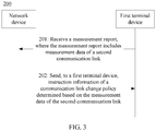
- FIG. 3 is a schematic interaction diagram of a communication method 200 according to another embodiment of the present invention. As shown in FIG. 3 , the method 200 includes steps 201 and 202.
- a network device receives a measurement report sent by a first terminal device, where the measurement report includes measurement data of a currently used second communication link.
- the measurement report may include only one piece of measurement data, namely, the measurement data of the currently used second communication link.
- the measurement report is sent to the network device when the first terminal device communicates with the second terminal device by using the currently used second communication link.
- a current state of the first terminal device is that the first terminal device is connected to a second terminal device.
- the first terminal device is currently performing D2D link communication.
- the first terminal device may measure signal quality of a Uu communication link (namely, the first communication link) based on measurement configuration information indicated by the network device.
- the signal quality of the Uu communication link is better than signal quality of a currently used PC5 communication link (namely, the currently used second communication link)
- the first terminal device sends the measurement data of the currently used second communication link to the network device.
- the first terminal device may report the measurement report to the network device directly or by using a relay device.
- the first terminal device reports the measurement report by using a relay device
- the first terminal device may perform the reporting based on a reporting condition provided in this embodiment of the present invention.
- a process in which the first terminal device directly reports the measurement data of the first communication link may be the same as that in the prior art, and details are not described herein again.
- the network device sends instruction information of a communication link change policy to the first terminal device.
- the instruction information is used to instruct the first terminal device to perform change processing on a communication link based on the communication link change policy, where the communication link includes the first communication link and/or the second communication link.
- the network device determines the communication link change policy based on the measurement data of the second communication link.
- the network device compares the measurement data of the second communication link with the measurement data of the first communication link, to determine the communication link change policy.
- the network device sends the instruction information of the communication link change policy to the first terminal device, to instruct the first terminal device to perform change processing on the communication link based on the communication link change policy indicated by the network device.
- the first terminal device further needs to report the measurement data of the first communication link to the network device. If the first terminal device reports the measurement data of the first communication link by using a relay device, the first terminal device may perform the reporting based on the reporting condition provided in this embodiment of the present invention. If the first terminal device directly reports the measurement data of the first communication link to the network device, a specific reporting process may be the same as that in the prior art, and details are not described herein again.
- the network device before the network device receives the measurement report sent by the first terminal device, the network device further needs to send the measurement configuration information and a normalized parameter to the first terminal device, where the measurement configuration information includes a measurement object (for example, a carrier frequency for D2D communication) and the reporting condition.
- a measurement object for example, a carrier frequency for D2D communication
- the measurement configuration information includes a measurement object (for example, a carrier frequency for D2D communication) and the reporting condition.
- the reporting condition may include at least one of the following: the signal quality of the currently used second communication link is lower than a fourth preset threshold; and a difference between the signal quality of the currently used second communication link and the signal quality of the first communication link is lower than a fifth preset threshold.
- a first preset threshold, a second preset threshold, a third preset threshold, the fourth preset threshold, and the fifth preset threshold are merely used for differentiating between different thresholds and have no necessary connection or value relationship between each other.
- the signal quality includes any one of reference signal received power RSRP, reference signal received quality RSRQ, a signal to interference plus noise ratio SINR, and a signal-to-noise ratio SNR.
- the first terminal device when communicating with the second terminal device by using the second communication link, the first terminal device may instantly measure the signal quality of the first communication link (for example, the Uu communication link), and report the signal quality of the first communication link to the base station, so that the base station may compare the measurement data of the second communication link (for example, the PC5 communication link) with the measurement data of the first communication link, and further control the first terminal device to use a communication link with lower power consumption for communication, thereby reducing power consumption of the first terminal device.
- the base station may compare the measurement data of the second communication link (for example, the PC5 communication link) with the measurement data of the first communication link, and further control the first terminal device to use a communication link with lower power consumption for communication, thereby reducing power consumption of the first terminal device.
- remote UE also referred to as a remote device
- relay UE is merely used as an example of the second terminal device. This should not be construed as any limitation on an application scope of the communication method in this embodiment of the present invention.
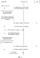
- FIG. 4A and FIG. 4B are a schematic interaction diagram of a communication method according to an embodiment of the present invention. As shown in FIG. 4A and FIG. 4B , a main procedure includes steps 301 to 317.
- this embodiment is applicable to a case in which remote UE and an eNB are currently in a connected state (also referred to as a radio resource control connected RRC_CONNECTED state).
- the eNB configures a normalized parameter for the remote UE.
- the normalized parameter may also be referred to as normalization (normalization) parameter.
- the normalized parameter is used by the remote UE to perform normalized processing on a measurement result.
- the remote UE needs to perform measurement on relay UE and the eNB.
- transmit power of the relay UE and that of the eNB may be different, or objects of the measurement performed by the remote UE on the relay UE and the eNB may be different, or density of a reference signal sent by the relay UE is less than that of the eNB, or transmit strength of a reference signal sent by the relay UE is less than that of the eNB, or the like.
- Measurement data is incomparable if direct comparison is performed. Therefore, the eNB needs to configure a normalized parameter for the remote UE, so that the remote UE performs normalized processing on measured measurement results of the relay UE and the eNB, to obtain comparable measurement data.
- the normalized parameter may include at least one of the following parameters: transmit power of the network device, transmit power of at least one second terminal device configured by the network device, a first carrier frequency used by a first communication link, a D2D carrier frequency, and a threshold for comparing measurement results.
- the remote UE evaluates a remaining quantity of electricity of the remote UE and a self-capability.
- the remote UE may not use the relay UE to perform communication.
- the remote UE may use the relay UE to perform communication only when the remaining quantity of electricity is small.
- That the remote UE evaluates a self-capability is that the remote UE evaluates whether the remote UE has a capability of searching for relay UE and using the relay UE to perform communication with the eNB.
- no conditional limitation is imposed on the relay UE searching performed by the remote UE.
- the remote UE may search for relay UE any time when the remote UE performs communication with the eNB, instead of searching for relay UE only when the remaining quantity of electricity is less than a preset threshold.
- the remote UE reports indication information to the eNB.
- the indication information may indicate that the remote UE has insufficient electricity, or indicates the remaining quantity of electricity of the remote UE.
- the indication information may further indicate that the remote UE has the capability of searching for relay UE and using the relay UE to perform communication with the eNB.
- the reported indication information may be triggered by an electricity threshold.
- the eNB may configure an electricity threshold for the remote UE, and step 302 is triggered only when a quantity of electricity of the remote UE is less than the threshold.
- the electricity threshold specified, a quantity of remote UEs that search for relay UE may be controlled, to reduce power consumption of the relay UE.
- the reported indication information may be triggered by a signal quality threshold.
- the eNB sets a signal quality threshold for the remote UE.
- Step 302 is triggered when signal quality of a reference signal that is sent by the eNB and that is received by the remote UE is lower than the signal quality threshold.
- steps 301, 302, and 303 are optional steps.
- the eNB instructs the remote UE to perform relay UE discovery.
- the eNB may instruct, based on a load status of the eNB after receiving the indication information reported by the remote UE, the remote UE to search for relay UE.
- the eNB directly instructs the remote UE to perform relay UE discovery.
- relay UE discovery herein should not be limited only to discovering relay UE, and may also be instruction information for instructing, by the eNB, the remote UE to connect to the relay UE.
- the eNB needs to allocate D2D resources to UEs that perform D2D communication.
- the D2D resources allocated by the eNB are uplink resources scheduled by the eNB for uplink communication between the eNB and UE. If these uplink resources are used as D2D resources, resources scheduled by the eNB for other UEs are interfered with or reduced. Therefore, when the eNB allocates D2D resources, if load of the eNB is not heavy, the eNB is capable of providing these D2D resources, to instruct the remote UE to search for relay UE. However, if the load of the eNB is heavy, the eNB may be incapable of providing these D2D resources. In this case, the eNB does not instruct the remote UE to search for relay UE.
- the remote UE sends a solicitation message (solicitation) to search for the relay UE.
- the remote UE sends the solicitation message.
- Relay UE receiving the solicitation message replies to the remote UE with a response message (Response).
- the remote UE receiving this response message (Response) can find that there is relay UE nearby (mode 1).
- relay UE periodically sends announcement messages (Announcement).
- the remote UE may listen to the announcement message (Announcement). If detecting this message through listening, the remote UE may find that there is relay UE near the remote UE (mode 2).
- the foregoing modes 1 and 2 are modes for discovering (or searching for) relay UE by the remote UE.
- the two modes may be implemented through the prior art, and details are not described herein.
- the eNB sends measurement configuration information to the remote UE.
- the eNB needs to configure the remote UE to perform signal measurement and measurement data (namely, measurement result) reporting.
- step 307 may be executed after step 306.
- step 307 may also be executed after step 303. If step 307 is executed after step 303, the measurement configuration information configured by the eNB for the remote UE may be sent to the remote UE in step 304.
- the measurement configuration information may include a measurement object and a reporting condition.
- the measurement object may include any one or more of the following: carrier frequencies of Universal Mobile Telecommunications System Terrestrial Radio Access (Universal Mobile Telecommunication System terrestrial radio access, UMTS terrestrial radio access, UTRA), evolved Universal Mobile Telecommunications System Terrestrial Radio Access (Evolved UTRA, EUTRA), a Global System for Mobile Communications/Enhanced Data rates for GSM Evolution radio access network (GSM/EDGE Radio Access Network, GERAN), Code Division Multiple Access (Code Division Multiple Access, CDMA) 2000, and a wireless local area network (Wireless Local Area Networks, WLAN).
- carrier frequencies of Universal Mobile Telecommunications System Terrestrial Radio Access Universal Mobile Telecommunication System terrestrial radio access, UMTS terrestrial radio access, UTRA
- Evolved UTRA EUTRA
- GSM/EDGE Radio Access Network GSM/EDGE Radio Access Network
- CDMA Code Division Multiple Access
- WLAN wireless local area network
- Measurement of the foregoing carrier frequencies may be the same as that in the prior art.
- the eNB may further configure the D2D carrier frequency for the remote UE.
- the D2D carrier frequency may include a carrier frequency for D2D communication based on a Long Term Evolution LTE system, a carrier frequency for D2D communication based on a wireless local area network WLAN, and a carrier frequency for D2D communication based on Bluetooth.
- the eNB configures a new measurement object (to be specific, configures the carrier frequency for D2D communication) for the remote UE, and the eNB may control the remote UE to perform measurement on different measurement objects. This can reduce power consumption caused by automatically enabling measurement by the remote UE in the prior art.
- the remote UE when the reporting condition is met, the remote UE sends a measurement report to the eNB.
- the reporting condition may include at least one of the following:
- the remote UE may report the measurement report according to a trigger or a new period.
- reporting according to a trigger may include the following cases:
- Reporting is triggered when signal quality of a D2D communication link (corresponding to a second communication link) is higher than a threshold, in other words, when the remote UE finds that relay UE is at a close distance to the remote UE.
- Reporting is triggered when signal quality of a D2D communication link is higher than a threshold of signal quality of a Uu communication link (corresponding to the first communication link).
- Reporting according to a period includes the following cases: Reporting is performed according to a period when signal quality of a D2D communication link is higher than a threshold of signal quality of a Uu communication link.
- Reporting is performed according to a period when signal quality of a D2D communication link is lower than a threshold.
- the eNB configures a new measurement reporting condition for the remote UE, so that the remote UE can be instantly triggered to report measurement data when the remote UE discovers a PC5 link that consumes less power or has better signal quality than a Uu link. In this way, the eNB can instantly decide whether a communication link currently used by the remote UE needs to be changed.
- the remote UE receives the measurement configuration information sent by the eNB, performs measurement based on the measurement object configured by the eNB, and reports measured measurement data (or a measurement result) based on the reporting condition.
- the remote UE may obtain the signal quality of the D2D communication link by measuring the following parameter:
- the remote UE can measure the signal quality of the D2D communication link.
- the remote further needs to measure the signal quality of the first communication link when the remote UE communicates with the eNB by using the first communication link.
- Measurement of signal quality of a reference signal sent by the eNB may be the same as that in the prior art, and details are not described herein.
- the remote UE compares measurement results.
- the remote UE separately measures the signal quality of the D2D communication link (namely, the second communication link) and the signal quality of the Uu communication link (namely, the first communication link).
- the remote UE compares the signal quality of the D2D communication link with the signal quality of the Uu communication link, to determine the measurement data that meets the reporting condition.
- the remote UE When comparing measurement data, the remote UE needs to use the normalized parameter sent by the eNB in step 301 to perform normalized processing on the measured measurement data of the D2D communication link and the Uu communication link.
- the following describes a method for using the normalized parameter by using an example.
- the normalized parameter sent by the eNB to the remote UE in step 301 is transmit power P eNB0 of the eNB and transmit power P relay0 of the relay UE.
- the transmit power of the relay UE is transmit power configured by the eNB for use by the relay UE.
- strength or quality that is measured by the remote UE and that is of signals transmitted by the eNB and the relay UE is separately P eNB and P relay
- the remote UE can directly compare the normalized results N eNB and N relay .
- the remote UE may measure signal quality of a plurality of D2D communication links (in other words, the remote UE may discover a plurality of relay UEs), and D2D communication is performed on the plurality of D2D communication links based on different technologies, for example, some D2D communication links are based on an LTE technology while some D2D communication links are based on a Bluetooth technology.
- the eNB configures a plurality of sets of normalized parameters. D2D communication links established based on a same technology use a same set of normalized parameters. For example, second terminal devices corresponding to second communication links that are based on the LTE technology use one set of normalized parameters, while second terminal devices corresponding to second communication links that are based on the Bluetooth technology use another set of normalized parameters.
- step 309 by comparing results obtained after the normalized processing, the remote UE can determine the measurement data that meets the reporting condition (referring to the description of the reporting condition in step 307).
- step 310 it is considered that the remote UE may discover a plurality of relay UEs, and if the plurality of relay UEs all meet the reporting condition, the remote UE may perform the reporting in either of the following manners:
- the remote UE may select a plurality of reporting forms:
- “good” signal quality may be measured from two aspects.
- “good” signal quality means that the remote UE uses lower receive power, has better received quality, has a higher signal to noise ratio, or the like when receiving a signal.
- “good” signal quality further means that the remote UE performs communication at lower power consumption (or means that the remote UE can use lower transmit power).
- the eNB sends D2D connection establishment instruction information to the remote UE based on the measurement report.
- step 311 the eNB determines, based on the measurement data reported by the remote UE, that the remote UE needs to connect to the relay UE.
- the eNB may select one piece of measurement data of best signal quality or highest signal strength from the plurality of pieces of measurement data, and send an index of the measurement data to the remote UE.
- the eNB instructs the remote UE to establish a connection to relay UE corresponding to the index (namely, target relay UE).
- the eNB may select one piece of measurement data of best quality or highest signal strength from the plurality of pieces of measurement data, and send a device ID corresponding to the measurement data to the remote UE. In this way, the remote UE may determine, based on the device ID, the relay UE indicated by the eNB (namely, target relay UE).
- the eNB determines, based on only signal quality or signal strength, that the remote UE needs to establish a connection to the relay UE is used only as an example for description above. Obviously, the eNB may further perform selection with reference to other factors or parameters. This embodiment of the present invention imposes no limitation thereto.
- the remote UE sends a connection establishment request to the relay UE.
- Step 312 may be the same as that in the prior art.
- Steps 313 to 317 Change a communication link.
- steps 313 to 317 may be the same as that in the prior art, and details are not described herein.
- the remote UE compares signal quality of a Uu interface with signal quality of a PC5 interface.
- the remote UE reports the measurement data to the eNB, so that the eNB changes a communication link for the remote UE based on the measurement data. In this way, power consumption of the remote UE can be reduced.
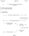
- FIG. 5 is a schematic interaction diagram of a communication method according to another embodiment of the present invention. As shown in FIG. 5 , a main procedure includes steps 401 to 418.
- this embodiment is applicable to a case in which remote UE and an eNB are currently in a connected state (also referred to as a radio resource control connected RRC_CONNECTED state).
- the eNB sends uplink power control configuration information to the remote UE.
- step 401 the eNB performs uplink power control on the remote UE, and a specific process may be the same as that in the prior art.
- the eNB may include a normalized parameter into the uplink power control configuration information.
- a normalized parameter For a description of the normalized parameter, refer to step 301 above.
- the normalized parameter refer to step 309 above.
- the remote UE estimates uplink transmit power.
- the remote UE estimates uplink power (or reference signal transmit power of the remote UE) based on the uplink power control configuration information sent by the eNB in step 401 and measurement performed on the eNB.
- the uplink power of the remote UE is denoted as P 1 below.
- the nominal power P 0 and open-loop path loss compensation ⁇ are configured by the eNB in measurement configuration information for the remote UE.
- the dynamic offset may be understood as a power value incremented or decremented based on the open-loop power control point.
- the dynamic offset includes two parts: power control based on a modulation and coding scheme (Modulation and Coding Scheme, MCS) and closed-loop power control.
- MCS Modulation and Coding Scheme
- the foregoing MCS-based power control is that the eNB adjusts power by adjusting an MCS of the remote UE.
- the closed-loop power control is that a transmit power control (Transmit Power Control, TPC) command is used to instruct the remote UE to offset a transmit power value.
- TPC Transmit Power Control
- the remote UE evaluates a remaining quantity of electricity and a capability.
- the remote UE reports indication information.
- the eNB sends a relay discovery instruction to the remote UE.
- steps 402 to 405 are optional steps.
- the remote UE sends a solicitation message.
- Relay UE sends a response message to the remote UE or relay UE sends announcement messages according to a period.
- step 407 the response message or the announcement message sent by the relay UE carries transmit power P 2 of the relay UE.
- steps 403 to 407 refer to steps 302 to 306 above, and details are not described herein again.
- the remote UE estimates transmit power of a sidelink (namely, a D2D communication link).
- the remote UE estimates transmit power on a PC5 interface. In an estimation process, the remote UE needs to use the transmit power value of the relay UE. The remote UE may obtain the transmit power of the relay UE through step 307.
- the remote UE compares values of P 1 and P 2 .
- the remote UE reports an estimation report to the eNB.
- step 310 For a process in which the remote UE reports the estimation report to the eNB, refer to step 310 above.
- the eNB selects relay UE (namely, target relay UE) corresponding to data (a power value herein) of best signal quality or highest signal strength from the estimation report.
- the eNB sends a relay connection instruction to the remote UE.
- the eNB instructs the remote UE to establish a connection to the target relay UE.
- the remote UE sends a direct connection request to target relay UE.
- a communication link change process is performed subsequently, where the remote UE switches from a Uu interface to a PC5 interface of the target relay UE.
- a specific procedure may be the same as that in the prior art, and details are not described herein.
- the remote UE estimates transmit power on the Uu interface and the transmit power on the PC5 interface based on the uplink transmit power. Transmit power of a Uu communication link and transmit power of a PC5 communication link are compared to determine a communication link with lower power consumption, and an estimation result is reported to the eNB, so that eNB controls a communication link change of the remote UE, thereby reducing power consumption of the remote UE.
- the eNB may select, from the several relay UEs based on at least one piece of measurement data reported by the remote UE, some relay UEs that need to be released, and instruct the remote UE to release the selected relay UEs.
- the eNB may add several relay UEs for the remote UE based on at least one piece of measurement data reported by the remote UE.
- the eNB may instruct the remote UE to release these relay UEs that have poor signal quality or consume relatively high power. For another example, if the eNB finds, from the at least one piece of measurement data reported by the remote UE, that the remote UE consumes relatively low power or has relatively good signal quality when communicating with some relay UEs, in this case, the eNB may instruct the remote UE to establish connections to these relay UEs that are corresponding to measurement data of relatively good signal quality or relatively low power consumption.
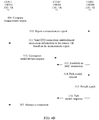
- FIG. 6 is a schematic interaction diagram of a communication method according to still another embodiment of the present invention. As shown in FIG. 6 , a main procedure includes steps 501 to 511.
- this embodiment is applicable to a case in which remote UE and relay UE are currently in a connected state and the remote UE changes a sidelink to an uplink/downlink.
- An eNB sends measurement configuration information to the remote UE.
- the measurement configuration information includes a measurement object on a Uu interface, a measurement object on a PC5 interface, and the like. Specific content is the same as that described above.
- a reporting condition in this case is different from that in case 1 above.
- the reporting condition herein may be as follows: Signal quality of a currently used second communication link is lower than a fourth preset threshold; and a difference between the signal quality of the currently used second communication link and signal quality of the first communication link is less than a fifth preset threshold.
- reporting by a first terminal device is triggered if signal quality of the D2D link is relatively poor or if the signal quality of the first communication link measured by the remote UE is higher than that of the currently used second communication link.
- the remote UE may also perform reporting according to a period.
- the remote UE performs measurement based on the measurement configuration information.
- the remote UE separately measures signal quality of a Uu communication link and signal quality of a PC5 communication link.
- the remote UE compares measurement results.
- the remote UE reports a measurement report.
- the eNB performs communication link change control.
- the eNB sends relay release instruction information to the remote UE.
- the eNB sends the relay release instruction information to the remote UE when the eNB determines, based on measurement data in the measurement report, to change a communication link of the remote UE.
- the relay release instruction information instructs the remote UE to release a connection to relay UE that currently communicates with the remote UE.
- the relay release instruction information may carry information for configuring a data plane bearer between the remote UE and the eNB.
- content indicated in the relay release instruction information may be carried by using an RRC reconfiguration message in the prior art.
- the eNB performs new measurement configuration for the remote UE and triggers the remote UE to report measurement data.
- the eNB determines that the signal quality of the Uu communication link is higher than the signal quality of the current PC5 communication link, the eNB controls the remote UE to instantly change to the Uu communication link, so that the remote UE can perform communication in real time by using a communication link with lower power consumption.
- FIG. 7 is a schematic block diagram of a network device 600 according to an embodiment of the present invention.
- the network device is configured in a communications system including a first terminal device and at least one second terminal device.
- the network device communicates with the first terminal device by using a first communication link, the first terminal device communicates with the at least one second terminal device by using at least one second communication link, and the at least one second terminal device is in a one-to-one correspondence with the at least one second communication link.
- the network device 600 includes:
- the network device determines the communication link change policy based on the at least one piece of measurement data.
- the at least one piece of measurement data is in a one-to-one correspondence with at least one to-be-selected second terminal device, where the at least one to-be-selected second terminal device is some or all of the at least one second terminal device.
- the units of the network device 600 in this embodiment of the present invention and the foregoing and other operations or functions are used to implement corresponding procedures executed by the network device in the method 100 or 200. For brevity, details are not described herein again.
- the first terminal device when performing communication (for example, communication with the network device or D2D communication), may instantly measure signal quality of the second communication link (namely, D2D link) and signal quality of the first communication link, and report measured measurement data of the one or more second communication links to the network device.
- the network device compares the measurement data of the second communication link with measurement data of the first communication link, to determine the communication link change policy of the first terminal device, and further control the first terminal device to use a communication link with lower power consumption for communication, thereby reducing power consumption of the first terminal device.
- FIG. 8 is a schematic block diagram of a terminal device 700 according to an embodiment of the present invention.
- the terminal device is configured in a communications system including a network device and at least one second terminal device, where the network device communicates with the first terminal device by using a first communication link, the first terminal device communicates with the at least one second terminal device by using at least one second communication link, and the at least one second terminal device is in a one-to-one correspondence with the at least one second communication link.
- the terminal device includes:
- the network device determines the communication link change policy based on the at least one piece of measurement data.
- the at least one piece of measurement data is in a one-to-one correspondence with at least one to-be-selected second terminal device, where the at least one to-be-selected second terminal device is some or all of the at least one second terminal device.
- the units of the terminal device 700 in this embodiment of the present invention and the foregoing and other operations or functions are used to implement corresponding procedures executed by the first terminal device in the method 100 or 200. For brevity, details are not described herein again.
- the first terminal device when performing communication (for example, direct communication with the network device or D2D communication), may instantly measure signal quality of the second communication link (namely, D2D link) and signal quality of the first communication link, and report measured measurement data of the one or more second communication links to the network device.
- the network device compares the measurement data of the second communication link with measurement data of the first communication link, to determine the communication link change policy of the first terminal device, and further control the first terminal device to use a communication link with lower power consumption for communication, thereby reducing power consumption of the first terminal device.
- the foregoing describes the communication method in the embodiments of the present invention in detail with reference to FIG. 2 to FIG. 6 .
- the following describes a network device and a terminal device in the embodiments of the present invention in detail with reference to FIG. 9 to FIG. 10 .
- FIG. 9 is a schematic structural diagram of a network device 1000 according to an embodiment of the present invention.
- the network device 1000 is configured in a communications system including a first terminal device and at least one second terminal device, where the network device communicates with the first terminal device by using a first communication link, the first terminal device communicates with the at least one second terminal device by using at least one second communication link, and the at least one second terminal device is in a one-to-one correspondence with the at least one second communication link.
- the network device 1000 includes a receiver 1100, a transmitter 1200, a processor 1300, a memory 1400, and a bus system 1500.
- the receiver 1100, the transmitter 1200, the processor 1300, and the memory 1400 are connected to each other by using the bus system 1500.
- the memory 1400 is configured to store an instruction
- the processor 1300 is configured to execute the instruction stored by the memory 1400, to control the receiver 1100 to receive a signal and control the transmitter 1200 to send a signal
- the receiver 1100 is configured to receive a measurement report sent by the first terminal device, where the measurement report includes at least one piece of measurement data
- the transmitter 1200 is configured to send instruction information of a communication link change policy to the first terminal device, where the instruction information is used to instruct the first terminal device to perform change processing on a communication link based on the communication link change policy, and the communication link includes the first communication link and/or the second communication link.
- the network device determines the communication link change policy based on the at least one piece of measurement data.
- the at least one piece of measurement data is in a one-to-one correspondence with at least one to-be-selected second terminal device, where the at least one to-be-selected second terminal device is some or all of the at least one second terminal device.
- the processor 1300 may be a central processing unit (central processing unit, "CPU” for short), or the processor 1300 may be another general-purpose processor, a digital signal processor (DSP), an application-specific integrated circuit (ASIC), a field programmable gate array (FPGA), or another programmable logic device, discrete gate or transistor logic device, discrete hardware component, or the like.
- the general-purpose processor may be a microprocessor, or the processor may be any conventional processor or the like.
- the memory 1400 may include a read-only memory and a random access memory, and provide an instruction and data to the processor 1300.
- a part of the memory 1400 may further include a non-volatile random access memory.
- the memory 1400 may further store information about a device type.
- the bus system 1500 may further include a power bus, a control bus, a status signal bus, and the like, in addition to a data bus.
- a power bus may further include a power bus, a control bus, a status signal bus, and the like, in addition to a data bus.
- various types of buses in the figure are marked as the bus system 1500.
- steps in the foregoing methods can be implemented by using a hardware integrated logical circuit in the processor 1300, or by using instructions in a form of software.
- the steps of the communication method disclosed with reference to the embodiments of the present invention may be directly performed by a hardware processor, or may be performed by using a combination of hardware in the processor and a software module.
- a software module may be located in a mature storage medium in the art, for example, a random access memory, a flash memory, a read-only memory, a programmable read-only memory, an electrically erasable programmable memory, or a register.
- the storage medium is located in the memory 1400, and the processor 1300 reads information in the memory 1400 and completes the steps in the foregoing methods in combination with hardware of the processor. To avoid repetition, details are not described herein again.
- the units of the network device 1000 in this embodiment of the present invention and the foregoing and other operations or functions are used to implement corresponding procedures executed by the network device in the method 100 or 200. For brevity, details are not described herein again.
- the first terminal device when performing communication (for example, direct communication with the network device or D2D communication), may instantly measure signal quality of the second communication link (namely, D2D link) and signal quality of the first communication link, and report measured measurement data of the one or more second communication links to the network device.
- the network device compares the measurement data of the second communication link with measurement data of the first communication link, to determine the communication link change policy of the first terminal device, and further control the first terminal device to use a communication link with lower power consumption for communication, thereby reducing power consumption of the first terminal device.
- FIG. 10 is a schematic structural diagram of a terminal device 2000 according to an embodiment of the present invention.
- the terminal device is configured in a communications system including a network device and at least one second terminal device, where the network device communicates with the terminal device by using a first communication link, the terminal device communicates with the at least one second terminal device by using at least one second communication link, and the at least one second terminal device is in a one-to-one correspondence with the at least one second communication link.
- the terminal device 2000 includes a receiver 2100, a transmitter 2200, a processor 2300, a memory 2400, and a bus system 2500.
- the receiver 2100, the transmitter 2200, the processor 2300, and the memory 2400 are connected to each other by using the bus system 2500.
- the memory 2400 is configured to store an instruction
- the processor 2300 is configured to execute the instruction stored by the memory 2400, to control the receiver 2100 to receive a signal and control the transmitter 2200 to send a signal, where the transmitter 2200 is configured to send a measurement report to the network device, where the measurement report includes at least one piece of measurement data;
- the receiver 2100 is configured to receive instruction information that is sent by the network device and that is of a communication link change policy;
- the processor 2300 is configured to perform change processing on a communication link based on the communication link change policy, where the communication link includes the first communication link and/or the second communication link.
- the network device determines the communication link change policy based on the at least one piece of measurement data.
- the at least one piece of measurement data is in a one-to-one correspondence with at least one to-be-selected second terminal device, where the at least one to-be-selected second terminal device is some or all of the at least one second terminal device.
- the processor 2300 may be a central processing unit (central processing unit, "CPU” for short), or the processor 2300 may be another general-purpose processor, a digital signal processor (DSP), an application-specific integrated circuit (ASIC), a field programmable gate array (FPGA), or another programmable logic device, discrete gate or transistor logic device, discrete hardware component, or the like.
- the general-purpose processor may be a microprocessor, or the processor may be any conventional processor or the like.
- the memory 2400 may include a read-only memory and a random access memory, and provide an instruction and data for the processor 2300.
- a part of the memory 2400 may further include a non-volatile random access memory.
- the memory 2400 may further store information about a device type.
- the bus system 2500 may further include a power bus, a control bus, a status signal bus, and the like, in addition to a data bus.
- a power bus may further include a power bus, a control bus, a status signal bus, and the like, in addition to a data bus.
- various types of buses in the figure are marked as the bus system 2500.
- steps in the foregoing methods can be implemented by using a hardware integrated logical circuit in the processor 1300, or by using instructions in a form of software.
- the steps of the method disclosed with reference to the embodiments of the present invention may be directly performed by a hardware processor, or may be performed by using a combination of hardware in the processor and a software module.
- a software module may be located in a mature storage medium in the art, for example, a random access memory, a flash memory, a read-only memory, a programmable read-only memory, an electrically erasable programmable memory, or a register.
- the storage medium is located in the memory 2400, and the processor 2300 reads information in the memory 2400 and completes the steps in the foregoing methods in combination with hardware of the processor. To avoid repetition, details are not described herein again.
- the units of the terminal device 2000 in this embodiment of the present invention and the foregoing and other operations or functions are used to implement corresponding procedures executed by the first terminal device in the method 100 or 200. For brevity, details are not described herein again.
- the first terminal device when performing communication (for example, direct communication with the network device or D2D communication), may instantly measure signal quality of the second communication link (namely, D2D link) and signal quality of the first communication link, and report measured measurement data of the one or more second communication links to the network device.
- the network device compares the measurement data of the second communication link with measurement data of the first communication link, to determine the communication link change policy of the first terminal device, and further control the first terminal device to use a communication link with lower power consumption for communication, thereby reducing power consumption of the first terminal device.
- sequence numbers of the foregoing processes do not mean execution sequences in the embodiments of the present invention.
- the execution sequences of the processes should be determined based on functions and internal logic of the processes, and should not be construed as any limitation on the implementation processes of the embodiments of the present invention.
- the disclosed system, apparatus, and method may be implemented in other manners.
- the described apparatus embodiment is merely an example.
- the unit division is merely logical function division and may be other division in actual implementation.
- a plurality of units or components may be combined or integrated into another system, or some features may be ignored or may not be performed.
- the displayed or discussed mutual couplings or direct couplings or communication connections may be implemented by using some interfaces.
- the indirect couplings or communication connections between the apparatuses or units may be implemented in electronic, mechanical, or other forms.
- the units described as separate parts may or may not be physically separate, and parts displayed as units may or may not be physical units, may be located in one position, or may be distributed on a plurality of network units. Some or all of the units may be selected based on actual requirements to achieve the objectives of the solutions of the embodiments.
- functional units in the embodiments of the present invention may be integrated into one processing unit, or each of the units may exist alone physically, or two or more units are integrated into one unit.
- the functions When the functions are implemented in the form of a software functional unit and sold or used as an independent product, the functions may be stored in a computer-readable storage medium. Based on such an understanding, the technical solutions of the present invention essentially, or the part contributing to the prior art, or some of the technical solutions may be implemented in a form of a software product.
- the computer software product is stored in a storage medium, and includes several instructions for instructing a computer device (which may be a personal computer, a server, or a network device) to perform all or some of the steps of the methods described in the embodiments of the present invention.
- the foregoing storage medium includes any medium that can store program code, such as a USB flash drive, a removable hard disk, a read-only memory (ROM, Read-Only Memory), a random access memory (RAM, Random Access Memory), a magnetic disk, or an optical disc.
- program code such as a USB flash drive, a removable hard disk, a read-only memory (ROM, Read-Only Memory), a random access memory (RAM, Random Access Memory), a magnetic disk, or an optical disc.
Landscapes
- Engineering & Computer Science (AREA)
- Computer Networks & Wireless Communication (AREA)
- Signal Processing (AREA)
- Mobile Radio Communication Systems (AREA)
Applications Claiming Priority (1)
| Application Number | Priority Date | Filing Date | Title |
|---|---|---|---|
| PCT/CN2016/089912 WO2018010123A1 (zh) | 2016-07-13 | 2016-07-13 | 通信方法、网络设备和终端设备 |
Publications (3)
| Publication Number | Publication Date |
|---|---|
| EP3477996A4 EP3477996A4 (de) | 2019-05-01 |
| EP3477996A1 true EP3477996A1 (de) | 2019-05-01 |
| EP3477996B1 EP3477996B1 (de) | 2020-09-09 |
Family
ID=60952296
Family Applications (1)
| Application Number | Title | Priority Date | Filing Date |
|---|---|---|---|
| EP16908451.4A Active EP3477996B1 (de) | 2016-07-13 | 2016-07-13 | Netzwerk mit d2d-endgeräte |
Country Status (4)
| Country | Link |
|---|---|
| US (1) | US10979960B2 (de) |
| EP (1) | EP3477996B1 (de) |
| CN (1) | CN109479221B (de) |
| WO (1) | WO2018010123A1 (de) |
Cited By (4)
| Publication number | Priority date | Publication date | Assignee | Title |
|---|---|---|---|---|
| EP3952369A4 (de) * | 2019-03-29 | 2022-05-18 | Huawei Technologies Co., Ltd. | Kommunikationsverfahren und kommunikationsvorrichtung |
| EP3925261A4 (de) * | 2019-02-14 | 2022-10-05 | ZTE Corporation | Verbindungsmessungen für fahrzeug-d2d-verbindungen |
| EP4188033A4 (de) * | 2020-08-07 | 2023-09-27 | Huawei Technologies Co., Ltd. | Verfahren und vorrichtung zur verbindungsumschaltung während einer sidelink-kommunikation |
| EP4395408A1 (de) * | 2022-12-27 | 2024-07-03 | SHARP Kabushiki Kaisha | Endgerätevorrichtung, basisstationsvorrichtung, verfahren und integrierte schaltung |
Families Citing this family (38)
| Publication number | Priority date | Publication date | Assignee | Title |
|---|---|---|---|---|
| WO2014031689A1 (en) | 2012-08-24 | 2014-02-27 | Oceus Networks Inc. | Mobile cellular networks |
| WO2014031597A1 (en) | 2012-08-24 | 2014-02-27 | Oceus Networks Inc. | Mobile cellular networks |
| WO2014179235A1 (en) | 2013-04-29 | 2014-11-06 | Oceus Networks Inc. | Mobile cellular network backhaul |
| US10873891B2 (en) | 2016-07-06 | 2020-12-22 | Oceus Networks, Llc | Secure network rollover |
| US9686238B1 (en) | 2016-07-07 | 2017-06-20 | Oceus Networks Inc. | Secure network enrollment |
| US9924427B2 (en) | 2016-07-07 | 2018-03-20 | Oceus Networks Inc. | Network backhaul access |
| AU2017405774A1 (en) * | 2017-03-23 | 2019-10-31 | Guangdong Oppo Mobile Telecommunications Corp., Ltd. | Switching method, network device and terminal device |
| US10172078B2 (en) | 2017-03-31 | 2019-01-01 | Oceus Networks Inc. | Targeted user equipment-base station communication link |
| CN110326334B (zh) * | 2017-04-28 | 2024-04-05 | Oppo广东移动通信有限公司 | 传输数据的方法、终端设备和网络设备 |
| CN109151886B (zh) * | 2017-06-16 | 2021-04-20 | 华为技术有限公司 | 一种用于上报的方法、设备和系统 |
| US11246031B2 (en) * | 2018-08-15 | 2022-02-08 | Oceus Networks, Llc | Disguising UE communications in a cellular network |
| CN111757550B (zh) * | 2019-03-28 | 2022-06-28 | 大唐移动通信设备有限公司 | 一种多载波直通链路管理方法及终端 |
| CN110213790B (zh) * | 2019-06-05 | 2022-09-02 | 潍坊医学院 | 一种用于运动监测的地理信息传输方法及系统 |
| US12267715B2 (en) | 2019-09-03 | 2025-04-01 | Qualcomm Incorporated | Sounding reference signal channel measurement for sidelink communication |
| CN112788620B (zh) * | 2019-11-07 | 2023-06-20 | 华为技术有限公司 | 一种信号处理方法、终端装置、网络装置和通信系统 |
| WO2021120030A1 (en) * | 2019-12-18 | 2021-06-24 | Mediatek Singapore Pte. Ltd. | Methods and apparatus of measurement configuration and report for sidelink open-loop power control |
| WO2021134756A1 (zh) * | 2020-01-02 | 2021-07-08 | Oppo广东移动通信有限公司 | 一种链路切换方法及装置、通信设备 |
| CN113453272B (zh) * | 2020-03-25 | 2023-11-10 | 维沃移动通信有限公司 | 副链路中继架构中的切换方法和设备 |
| EP4436311A3 (de) * | 2020-03-26 | 2024-12-04 | Kyocera Corporation | Kommunikationssteuerungsverfahren |
| EP4158946A4 (de) * | 2020-05-29 | 2024-01-24 | Qualcomm Incorporated | Entwurf eines sidelink-relaismobilitätsauslöserereignisses |
| US11356922B2 (en) * | 2020-08-17 | 2022-06-07 | Verizon Patent And Licensing Inc. | Path selection for integrated access and backhaul |
| CN114258070B (zh) * | 2020-09-21 | 2025-02-18 | 维沃移动通信有限公司 | Sl和wlan互操作方法、装置及通信设备 |
| WO2022082444A1 (en) * | 2020-10-20 | 2022-04-28 | Telefonaktiebolaget Lm Ericsson (Publ) | Method and apparatus for terminal device behavior classification |
| US20230363020A1 (en) * | 2020-10-22 | 2023-11-09 | Lg Electronics Inc. | Method and apparatus for performing mobility in wireless communication system |
| EP4268483A1 (de) * | 2020-12-22 | 2023-11-01 | Telefonaktiebolaget LM Ericsson (publ) | Endgerätevorrichtung, netzwerkknoten und verfahren darin zur messungsmeldung |
| US12395827B2 (en) * | 2021-02-11 | 2025-08-19 | Qualcomm Incorporated | Techniques for sidelink discovery between user equipments associated with different discovery models |
| US11671942B2 (en) * | 2021-04-02 | 2023-06-06 | Qualcomm Incorporated | Communication configuration for multi-hop networks using repeaters |
| CN115396976A (zh) * | 2021-05-24 | 2022-11-25 | 中国移动通信有限公司研究院 | 一种通信方法、链路选择方法、用户设备和网络侧设备 |
| WO2023287944A1 (en) * | 2021-07-15 | 2023-01-19 | Kyocera Corporation | Service continuity from indirect to direct communication triggered by base station request |
| CN113766673B (zh) * | 2021-09-17 | 2024-03-22 | 善悦(武汉)高新技术有限公司 | 一种小区户外组网用5g无线射频单元及其组网方法 |
| CN116137726A (zh) * | 2021-11-17 | 2023-05-19 | 大唐移动通信设备有限公司 | 数据传输方法、远端ue、中继ue及存储介质 |
| CN118355695A (zh) * | 2021-12-21 | 2024-07-16 | Oppo广东移动通信有限公司 | 无线通信的方法、终端设备及网络设备 |
| EP4496383B1 (de) * | 2022-03-31 | 2026-05-06 | Guangdong Oppo Mobile Telecommunications Corp., Ltd. | Verbindung eines endgeräts über ein nicht-3gpp-protokoll mit einem relais-endgerät und verbindung des relais-endgeräts über ein 3gpp-protokoll mit einem netzwerk |
| WO2023216180A1 (en) * | 2022-05-12 | 2023-11-16 | Nokia Shanghai Bell Co., Ltd. | Redundant user plane paths coordination based on multiple terminal devices per terminal device group |
| CN117177287A (zh) * | 2022-05-25 | 2023-12-05 | 维沃移动通信有限公司 | 测量报告的上报方法、装置、终端及网络侧设备 |
| WO2024065452A1 (zh) * | 2022-09-29 | 2024-04-04 | 北京小米移动软件有限公司 | 多路径通信方法、装置及系统 |
| CN121693948A (zh) * | 2023-08-08 | 2026-03-17 | 联发科技股份有限公司 | 移动通信中邻近区域网络设备的通信量计算方法和设备 |
| CN120302385A (zh) * | 2024-01-09 | 2025-07-11 | 维沃移动通信有限公司 | 终端节能测量及配置方法、装置和通信设备 |
Family Cites Families (16)
| Publication number | Priority date | Publication date | Assignee | Title |
|---|---|---|---|---|
| US7599341B2 (en) * | 2006-02-28 | 2009-10-06 | Motorola, Inc. | System and method for managing communication routing within a wireless multi-hop network |
| GB0907213D0 (en) * | 2009-04-27 | 2009-06-10 | Sharp Kk | Relay apparatus and method |
| US20120184306A1 (en) | 2009-09-28 | 2012-07-19 | Nokia Corporation | Random Access Process Reusing For D2D Probing in Cellular-Aided D2D Networks |
| US20110103240A1 (en) * | 2009-10-29 | 2011-05-05 | Qualcomm Incorporated | Method for forwarding in peer-to-peer wireless communications |
| US9232550B2 (en) * | 2011-03-31 | 2016-01-05 | Broadcom Corporation | Method and apparatus for facilitating device-to-device communication |
| EP2715981B1 (de) * | 2011-06-01 | 2018-11-28 | NTT DoCoMo, Inc. | Erweiterter lokaler zugriff in mobilkommunikationen |
| CN103024933B (zh) | 2011-09-28 | 2016-01-20 | 腾讯科技(深圳)有限公司 | 一种移动互联网访问系统及访问移动互联网的方法 |
| CN106604336B (zh) | 2011-09-29 | 2020-03-20 | 华为技术有限公司 | 通信模式切换的方法和装置 |
| US9591679B2 (en) * | 2012-09-17 | 2017-03-07 | Blackberry Limited | Initiation of inter-device communication in wireless communication systems |
| CN102983944A (zh) * | 2012-12-04 | 2013-03-20 | 中国联合网络通信集团有限公司 | 数据传输处理方法、装置和系统 |
| EP2878157B1 (de) * | 2013-04-24 | 2020-01-01 | Nec Corporation | Verfahren zur verwendung in der d2d-kommunikation und drahtloses kommunikationssystem |
| WO2015004142A1 (en) * | 2013-07-08 | 2015-01-15 | Nec Europe Ltd. | Method for deciding to handover user equipment in a mobile communicaton network |
| KR102098119B1 (ko) * | 2013-09-02 | 2020-04-07 | 삼성전자 주식회사 | 단말 간 직접 통신을 지원하는 무선 통신 시스템에서 데이터 경로 전환 방법 및 장치 |
| EP3103306B1 (de) * | 2014-02-04 | 2019-10-23 | Telefonaktiebolaget LM Ericsson (publ) | Verfahren, drahtlose vorrichtung, basisstation und kandidatenrelaisstation zur unterstützung von d2d-kommunikation über ein relais |
| EP3141063B1 (de) * | 2014-05-08 | 2019-09-11 | Telecom Italia S.p.A. | Ressourcenzuteilungssystem und -verfahren zur implementierung von vorrichtung-zu-vorrichtung-kommunikationen in drahtloskommunikationsnetzwerken |
| US10122801B2 (en) * | 2015-07-02 | 2018-11-06 | Qualcomm Incorporated | Service discovery and topology management |
-
2016
- 2016-07-13 WO PCT/CN2016/089912 patent/WO2018010123A1/zh not_active Ceased
- 2016-07-13 EP EP16908451.4A patent/EP3477996B1/de active Active
- 2016-07-13 CN CN201680087549.6A patent/CN109479221B/zh active Active
-
2019
- 2019-01-10 US US16/245,029 patent/US10979960B2/en active Active
Cited By (9)
| Publication number | Priority date | Publication date | Assignee | Title |
|---|---|---|---|---|
| EP3925261A4 (de) * | 2019-02-14 | 2022-10-05 | ZTE Corporation | Verbindungsmessungen für fahrzeug-d2d-verbindungen |
| EP4460152A2 (de) * | 2019-02-14 | 2024-11-06 | ZTE Corporation | Verbindungsmessungen für fahrzeug-vorrichtung-zu-vorrichtung-verbindungen |
| EP4460152B1 (de) * | 2019-02-14 | 2026-01-21 | ZTE Corporation | Verbindungsmessungen für fahrzeug-vorrichtung-zu-vorrichtung-verbindungen |
| EP3952369A4 (de) * | 2019-03-29 | 2022-05-18 | Huawei Technologies Co., Ltd. | Kommunikationsverfahren und kommunikationsvorrichtung |
| US11470662B2 (en) | 2019-03-29 | 2022-10-11 | Huawei Technologies Co., Ltd. | Communication method and communications apparatus |
| US12022541B2 (en) | 2019-03-29 | 2024-06-25 | Huawei Technologies Co., Ltd. | Communication method and communications apparatus |
| EP4188033A4 (de) * | 2020-08-07 | 2023-09-27 | Huawei Technologies Co., Ltd. | Verfahren und vorrichtung zur verbindungsumschaltung während einer sidelink-kommunikation |
| US12574953B2 (en) | 2020-08-07 | 2026-03-10 | Huawei Technologies Co., Ltd. | Link switching method in sidelink communication and apparatus |
| EP4395408A1 (de) * | 2022-12-27 | 2024-07-03 | SHARP Kabushiki Kaisha | Endgerätevorrichtung, basisstationsvorrichtung, verfahren und integrierte schaltung |
Also Published As
| Publication number | Publication date |
|---|---|
| CN109479221B (zh) | 2021-02-12 |
| EP3477996A4 (de) | 2019-05-01 |
| WO2018010123A1 (zh) | 2018-01-18 |
| US10979960B2 (en) | 2021-04-13 |
| US20190150057A1 (en) | 2019-05-16 |
| EP3477996B1 (de) | 2020-09-09 |
| CN109479221A (zh) | 2019-03-15 |
Similar Documents
| Publication | Publication Date | Title |
|---|---|---|
| US10979960B2 (en) | Communication method, network device, and terminal device supporting multimode communication links | |
| CN107770824B (zh) | 用于小区切换的方法、用户设备及网络设备 | |
| CN103370963B (zh) | 用于报告无线电接入技术间测量的方法和装置 | |
| US11882494B2 (en) | Mobile devices, network nodes and methods of operating the same | |
| US9294995B2 (en) | Activate ES cell for particular UE(s) | |
| JP5382389B2 (ja) | 通信システム | |
| US10206128B2 (en) | Communication system, apparatus and related methods of operation | |
| EP3962168B1 (de) | Signalmessverfahren und -vorrichtung | |
| CN109804664B (zh) | 用于无线网络中的测量和测量报告的方法和装置 | |
| US10484900B2 (en) | Method and device allowing terminal to report measurement result | |
| US20180220319A1 (en) | Method and device for terminal determining whether to report wlan measurement result | |
| US11172414B2 (en) | Coordinated cell determining method and network device | |
| JP2018530184A (ja) | チャネル測定とチャネル測定結果報告の方法 | |
| EP3324680B1 (de) | Fähigkeitsanzeigeverfahren, mobiles endgerät und netzwerkvorrichtung | |
| US11191015B2 (en) | Efficient communication of network identifiers | |
| JP7831608B2 (ja) | 情報を送受信する方法、装置及び通信システム | |
| US9319992B2 (en) | Measuring method and device before different-frequency handover of user terminal | |
| CN107155189B (zh) | 应用于超级小区的通信方法和装置 | |
| WO2016089280A2 (en) | Efficient communication of network identifiers | |
| US20140148167A1 (en) | Wireless communication system, wireless base station, wireless terminal, and communication control method | |
| EP4507378A1 (de) | Benutzergerät, basisstation, verfahren für benutzergerät und verfahren für basisstation | |
| EP2830358A1 (de) | Beurteilung, ob eine nicht aktivierte Kleinzelle aktiviert werden sollte, um einem Benutzergerät zu dienen | |
| JP2017532802A (ja) | 無線通信エネルギーを意識した電力共有無線資源方法および装置 |
Legal Events
| Date | Code | Title | Description |
|---|---|---|---|
| STAA | Information on the status of an ep patent application or granted ep patent |
Free format text: STATUS: THE INTERNATIONAL PUBLICATION HAS BEEN MADE |
|
| PUAI | Public reference made under article 153(3) epc to a published international application that has entered the european phase |
Free format text: ORIGINAL CODE: 0009012 |
|
| STAA | Information on the status of an ep patent application or granted ep patent |
Free format text: STATUS: REQUEST FOR EXAMINATION WAS MADE |
|
| 17P | Request for examination filed |
Effective date: 20190122 |
|
| A4 | Supplementary search report drawn up and despatched |
Effective date: 20190308 |
|
| AK | Designated contracting states |
Kind code of ref document: A1 Designated state(s): AL AT BE BG CH CY CZ DE DK EE ES FI FR GB GR HR HU IE IS IT LI LT LU LV MC MK MT NL NO PL PT RO RS SE SI SK SM TR |
|
| AX | Request for extension of the european patent |
Extension state: BA ME |
|
| DAV | Request for validation of the european patent (deleted) | ||
| DAX | Request for extension of the european patent (deleted) | ||
| RIC1 | Information provided on ipc code assigned before grant |
Ipc: H04W 84/18 20090101ALN20200127BHEP Ipc: H04W 36/16 20090101AFI20200127BHEP Ipc: H04W 24/02 20090101ALI20200127BHEP |
|
| GRAP | Despatch of communication of intention to grant a patent |
Free format text: ORIGINAL CODE: EPIDOSNIGR1 |
|
| STAA | Information on the status of an ep patent application or granted ep patent |
Free format text: STATUS: GRANT OF PATENT IS INTENDED |
|
| INTG | Intention to grant announced |
Effective date: 20200306 |
|
| GRAS | Grant fee paid |
Free format text: ORIGINAL CODE: EPIDOSNIGR3 |
|
| GRAA | (expected) grant |
Free format text: ORIGINAL CODE: 0009210 |
|
| STAA | Information on the status of an ep patent application or granted ep patent |
Free format text: STATUS: THE PATENT HAS BEEN GRANTED |
|
| AK | Designated contracting states |
Kind code of ref document: B1 Designated state(s): AL AT BE BG CH CY CZ DE DK EE ES FI FR GB GR HR HU IE IS IT LI LT LU LV MC MK MT NL NO PL PT RO RS SE SI SK SM TR |
|
| REG | Reference to a national code |
Ref country code: GB Ref legal event code: FG4D |
|
| REG | Reference to a national code |
Ref country code: AT Ref legal event code: REF Ref document number: 1313132 Country of ref document: AT Kind code of ref document: T Effective date: 20200915 Ref country code: CH Ref legal event code: EP |
|
| REG | Reference to a national code |
Ref country code: IE Ref legal event code: FG4D |
|
| REG | Reference to a national code |
Ref country code: DE Ref legal event code: R096 Ref document number: 602016043943 Country of ref document: DE |
|
| REG | Reference to a national code |
Ref country code: LT Ref legal event code: MG4D |
|
| PG25 | Lapsed in a contracting state [announced via postgrant information from national office to epo] |
Ref country code: BG Free format text: LAPSE BECAUSE OF FAILURE TO SUBMIT A TRANSLATION OF THE DESCRIPTION OR TO PAY THE FEE WITHIN THE PRESCRIBED TIME-LIMIT Effective date: 20201209 Ref country code: GR Free format text: LAPSE BECAUSE OF FAILURE TO SUBMIT A TRANSLATION OF THE DESCRIPTION OR TO PAY THE FEE WITHIN THE PRESCRIBED TIME-LIMIT Effective date: 20201210 Ref country code: LT Free format text: LAPSE BECAUSE OF FAILURE TO SUBMIT A TRANSLATION OF THE DESCRIPTION OR TO PAY THE FEE WITHIN THE PRESCRIBED TIME-LIMIT Effective date: 20200909 Ref country code: HR Free format text: LAPSE BECAUSE OF FAILURE TO SUBMIT A TRANSLATION OF THE DESCRIPTION OR TO PAY THE FEE WITHIN THE PRESCRIBED TIME-LIMIT Effective date: 20200909 Ref country code: SE Free format text: LAPSE BECAUSE OF FAILURE TO SUBMIT A TRANSLATION OF THE DESCRIPTION OR TO PAY THE FEE WITHIN THE PRESCRIBED TIME-LIMIT Effective date: 20200909 Ref country code: FI Free format text: LAPSE BECAUSE OF FAILURE TO SUBMIT A TRANSLATION OF THE DESCRIPTION OR TO PAY THE FEE WITHIN THE PRESCRIBED TIME-LIMIT Effective date: 20200909 Ref country code: NO Free format text: LAPSE BECAUSE OF FAILURE TO SUBMIT A TRANSLATION OF THE DESCRIPTION OR TO PAY THE FEE WITHIN THE PRESCRIBED TIME-LIMIT Effective date: 20201209 |
|
| REG | Reference to a national code |
Ref country code: AT Ref legal event code: MK05 Ref document number: 1313132 Country of ref document: AT Kind code of ref document: T Effective date: 20200909 |
|
| REG | Reference to a national code |
Ref country code: NL Ref legal event code: MP Effective date: 20200909 |
|
| PG25 | Lapsed in a contracting state [announced via postgrant information from national office to epo] |
Ref country code: RS Free format text: LAPSE BECAUSE OF FAILURE TO SUBMIT A TRANSLATION OF THE DESCRIPTION OR TO PAY THE FEE WITHIN THE PRESCRIBED TIME-LIMIT Effective date: 20200909 Ref country code: PL Free format text: LAPSE BECAUSE OF FAILURE TO SUBMIT A TRANSLATION OF THE DESCRIPTION OR TO PAY THE FEE WITHIN THE PRESCRIBED TIME-LIMIT Effective date: 20200909 Ref country code: LV Free format text: LAPSE BECAUSE OF FAILURE TO SUBMIT A TRANSLATION OF THE DESCRIPTION OR TO PAY THE FEE WITHIN THE PRESCRIBED TIME-LIMIT Effective date: 20200909 |
|
| PG25 | Lapsed in a contracting state [announced via postgrant information from national office to epo] |
Ref country code: PT Free format text: LAPSE BECAUSE OF FAILURE TO SUBMIT A TRANSLATION OF THE DESCRIPTION OR TO PAY THE FEE WITHIN THE PRESCRIBED TIME-LIMIT Effective date: 20210111 Ref country code: RO Free format text: LAPSE BECAUSE OF FAILURE TO SUBMIT A TRANSLATION OF THE DESCRIPTION OR TO PAY THE FEE WITHIN THE PRESCRIBED TIME-LIMIT Effective date: 20200909 Ref country code: CZ Free format text: LAPSE BECAUSE OF FAILURE TO SUBMIT A TRANSLATION OF THE DESCRIPTION OR TO PAY THE FEE WITHIN THE PRESCRIBED TIME-LIMIT Effective date: 20200909 Ref country code: EE Free format text: LAPSE BECAUSE OF FAILURE TO SUBMIT A TRANSLATION OF THE DESCRIPTION OR TO PAY THE FEE WITHIN THE PRESCRIBED TIME-LIMIT Effective date: 20200909 Ref country code: SM Free format text: LAPSE BECAUSE OF FAILURE TO SUBMIT A TRANSLATION OF THE DESCRIPTION OR TO PAY THE FEE WITHIN THE PRESCRIBED TIME-LIMIT Effective date: 20200909 |
|
| PG25 | Lapsed in a contracting state [announced via postgrant information from national office to epo] |
Ref country code: AT Free format text: LAPSE BECAUSE OF FAILURE TO SUBMIT A TRANSLATION OF THE DESCRIPTION OR TO PAY THE FEE WITHIN THE PRESCRIBED TIME-LIMIT Effective date: 20200909 Ref country code: AL Free format text: LAPSE BECAUSE OF FAILURE TO SUBMIT A TRANSLATION OF THE DESCRIPTION OR TO PAY THE FEE WITHIN THE PRESCRIBED TIME-LIMIT Effective date: 20200909 Ref country code: ES Free format text: LAPSE BECAUSE OF FAILURE TO SUBMIT A TRANSLATION OF THE DESCRIPTION OR TO PAY THE FEE WITHIN THE PRESCRIBED TIME-LIMIT Effective date: 20200909 Ref country code: IS Free format text: LAPSE BECAUSE OF FAILURE TO SUBMIT A TRANSLATION OF THE DESCRIPTION OR TO PAY THE FEE WITHIN THE PRESCRIBED TIME-LIMIT Effective date: 20210109 |
|
| REG | Reference to a national code |
Ref country code: DE Ref legal event code: R097 Ref document number: 602016043943 Country of ref document: DE |
|
| PG25 | Lapsed in a contracting state [announced via postgrant information from national office to epo] |
Ref country code: SK Free format text: LAPSE BECAUSE OF FAILURE TO SUBMIT A TRANSLATION OF THE DESCRIPTION OR TO PAY THE FEE WITHIN THE PRESCRIBED TIME-LIMIT Effective date: 20200909 |
|
| PLBE | No opposition filed within time limit |
Free format text: ORIGINAL CODE: 0009261 |
|
| STAA | Information on the status of an ep patent application or granted ep patent |
Free format text: STATUS: NO OPPOSITION FILED WITHIN TIME LIMIT |
|
| 26N | No opposition filed |
Effective date: 20210610 |
|
| PG25 | Lapsed in a contracting state [announced via postgrant information from national office to epo] |
Ref country code: DK Free format text: LAPSE BECAUSE OF FAILURE TO SUBMIT A TRANSLATION OF THE DESCRIPTION OR TO PAY THE FEE WITHIN THE PRESCRIBED TIME-LIMIT Effective date: 20200909 Ref country code: SI Free format text: LAPSE BECAUSE OF FAILURE TO SUBMIT A TRANSLATION OF THE DESCRIPTION OR TO PAY THE FEE WITHIN THE PRESCRIBED TIME-LIMIT Effective date: 20200909 |
|
| PG25 | Lapsed in a contracting state [announced via postgrant information from national office to epo] |
Ref country code: IT Free format text: LAPSE BECAUSE OF FAILURE TO SUBMIT A TRANSLATION OF THE DESCRIPTION OR TO PAY THE FEE WITHIN THE PRESCRIBED TIME-LIMIT Effective date: 20200909 |
|
| REG | Reference to a national code |
Ref country code: CH Ref legal event code: PL |
|
| GBPC | Gb: european patent ceased through non-payment of renewal fee |
Effective date: 20210713 |
|
| PG25 | Lapsed in a contracting state [announced via postgrant information from national office to epo] |
Ref country code: MC Free format text: LAPSE BECAUSE OF FAILURE TO SUBMIT A TRANSLATION OF THE DESCRIPTION OR TO PAY THE FEE WITHIN THE PRESCRIBED TIME-LIMIT Effective date: 20200909 |
|
| REG | Reference to a national code |
Ref country code: BE Ref legal event code: MM Effective date: 20210731 |
|
| PG25 | Lapsed in a contracting state [announced via postgrant information from national office to epo] |
Ref country code: LI Free format text: LAPSE BECAUSE OF NON-PAYMENT OF DUE FEES Effective date: 20210731 Ref country code: GB Free format text: LAPSE BECAUSE OF NON-PAYMENT OF DUE FEES Effective date: 20210713 Ref country code: CH Free format text: LAPSE BECAUSE OF NON-PAYMENT OF DUE FEES Effective date: 20210731 |
|
| PG25 | Lapsed in a contracting state [announced via postgrant information from national office to epo] |
Ref country code: LU Free format text: LAPSE BECAUSE OF NON-PAYMENT OF DUE FEES Effective date: 20210713 Ref country code: FR Free format text: LAPSE BECAUSE OF NON-PAYMENT OF DUE FEES Effective date: 20210731 |
|
| PG25 | Lapsed in a contracting state [announced via postgrant information from national office to epo] |
Ref country code: IE Free format text: LAPSE BECAUSE OF NON-PAYMENT OF DUE FEES Effective date: 20210713 Ref country code: BE Free format text: LAPSE BECAUSE OF NON-PAYMENT OF DUE FEES Effective date: 20210731 |
|
| PG25 | Lapsed in a contracting state [announced via postgrant information from national office to epo] |
Ref country code: NL Free format text: LAPSE BECAUSE OF NON-PAYMENT OF DUE FEES Effective date: 20200923 Ref country code: CY Free format text: LAPSE BECAUSE OF FAILURE TO SUBMIT A TRANSLATION OF THE DESCRIPTION OR TO PAY THE FEE WITHIN THE PRESCRIBED TIME-LIMIT Effective date: 20200909 |
|
| PG25 | Lapsed in a contracting state [announced via postgrant information from national office to epo] |
Ref country code: HU Free format text: LAPSE BECAUSE OF FAILURE TO SUBMIT A TRANSLATION OF THE DESCRIPTION OR TO PAY THE FEE WITHIN THE PRESCRIBED TIME-LIMIT; INVALID AB INITIO Effective date: 20160713 |
|
| PG25 | Lapsed in a contracting state [announced via postgrant information from national office to epo] |
Ref country code: MK Free format text: LAPSE BECAUSE OF FAILURE TO SUBMIT A TRANSLATION OF THE DESCRIPTION OR TO PAY THE FEE WITHIN THE PRESCRIBED TIME-LIMIT Effective date: 20200909 |
|
| PG25 | Lapsed in a contracting state [announced via postgrant information from national office to epo] |
Ref country code: MT Free format text: LAPSE BECAUSE OF FAILURE TO SUBMIT A TRANSLATION OF THE DESCRIPTION OR TO PAY THE FEE WITHIN THE PRESCRIBED TIME-LIMIT Effective date: 20200909 |
|
| PGFP | Annual fee paid to national office [announced via postgrant information from national office to epo] |
Ref country code: DE Payment date: 20250604 Year of fee payment: 10 |
|
| PG25 | Lapsed in a contracting state [announced via postgrant information from national office to epo] |
Ref country code: TR Free format text: LAPSE BECAUSE OF FAILURE TO SUBMIT A TRANSLATION OF THE DESCRIPTION OR TO PAY THE FEE WITHIN THE PRESCRIBED TIME-LIMIT Effective date: 20200909 |