EP3484352B1 - System umfassend ein implantat und ein implantierbares gerät zur transkutanen datenübertragung - Google Patents
System umfassend ein implantat und ein implantierbares gerät zur transkutanen datenübertragung Download PDFInfo
- Publication number
- EP3484352B1 EP3484352B1 EP17831704.6A EP17831704A EP3484352B1 EP 3484352 B1 EP3484352 B1 EP 3484352B1 EP 17831704 A EP17831704 A EP 17831704A EP 3484352 B1 EP3484352 B1 EP 3484352B1
- Authority
- EP
- European Patent Office
- Prior art keywords
- data
- implant
- sensed
- subcutaneous sensor
- sensor
- Prior art date
- Legal status (The legal status is an assumption and is not a legal conclusion. Google has not performed a legal analysis and makes no representation as to the accuracy of the status listed.)
- Active
Links
Images


Classifications
-
- A—HUMAN NECESSITIES
- A61—MEDICAL OR VETERINARY SCIENCE; HYGIENE
- A61B—DIAGNOSIS; SURGERY; IDENTIFICATION
- A61B5/00—Measuring for diagnostic purposes; Identification of persons
- A61B5/74—Details of notification to user or communication with user or patient; User input means
- A61B5/742—Details of notification to user or communication with user or patient; User input means using visual displays
- A61B5/7435—Displaying user selection data, e.g. icons in a graphical user interface
-
- A—HUMAN NECESSITIES
- A61—MEDICAL OR VETERINARY SCIENCE; HYGIENE
- A61B—DIAGNOSIS; SURGERY; IDENTIFICATION
- A61B5/00—Measuring for diagnostic purposes; Identification of persons
- A61B5/48—Other medical applications
- A61B5/4851—Prosthesis assessment or monitoring
-
- A—HUMAN NECESSITIES
- A61—MEDICAL OR VETERINARY SCIENCE; HYGIENE
- A61B—DIAGNOSIS; SURGERY; IDENTIFICATION
- A61B5/00—Measuring for diagnostic purposes; Identification of persons
- A61B5/0002—Remote monitoring of patients using telemetry, e.g. transmission of vital signals via a communication network
- A61B5/0015—Remote monitoring of patients using telemetry, e.g. transmission of vital signals via a communication network characterised by features of the telemetry system
- A61B5/002—Monitoring the patient using a local or closed circuit, e.g. in a room or building
-
- A—HUMAN NECESSITIES
- A61—MEDICAL OR VETERINARY SCIENCE; HYGIENE
- A61B—DIAGNOSIS; SURGERY; IDENTIFICATION
- A61B5/00—Measuring for diagnostic purposes; Identification of persons
- A61B5/0002—Remote monitoring of patients using telemetry, e.g. transmission of vital signals via a communication network
- A61B5/0026—Remote monitoring of patients using telemetry, e.g. transmission of vital signals via a communication network characterised by the transmission medium
- A61B5/0028—Body tissue as transmission medium, i.e. transmission systems where the medium is the human body
-
- A—HUMAN NECESSITIES
- A61—MEDICAL OR VETERINARY SCIENCE; HYGIENE
- A61B—DIAGNOSIS; SURGERY; IDENTIFICATION
- A61B5/00—Measuring for diagnostic purposes; Identification of persons
- A61B5/0002—Remote monitoring of patients using telemetry, e.g. transmission of vital signals via a communication network
- A61B5/0031—Implanted circuitry
-
- A—HUMAN NECESSITIES
- A61—MEDICAL OR VETERINARY SCIENCE; HYGIENE
- A61B—DIAGNOSIS; SURGERY; IDENTIFICATION
- A61B5/00—Measuring for diagnostic purposes; Identification of persons
- A61B5/68—Arrangements of detecting, measuring or recording means, e.g. sensors, in relation to patient
- A61B5/6846—Arrangements of detecting, measuring or recording means, e.g. sensors, in relation to patient specially adapted to be brought in contact with an internal body part, i.e. invasive
- A61B5/6847—Arrangements of detecting, measuring or recording means, e.g. sensors, in relation to patient specially adapted to be brought in contact with an internal body part, i.e. invasive mounted on an invasive device
- A61B5/686—Permanently implanted devices, e.g. pacemakers, other stimulators, biochips
-
- A—HUMAN NECESSITIES
- A61—MEDICAL OR VETERINARY SCIENCE; HYGIENE
- A61B—DIAGNOSIS; SURGERY; IDENTIFICATION
- A61B5/00—Measuring for diagnostic purposes; Identification of persons
- A61B5/74—Details of notification to user or communication with user or patient; User input means
- A61B5/746—Alarms related to a physiological condition, e.g. details of setting alarm thresholds or avoiding false alarms
-
- H—ELECTRICITY
- H02—GENERATION; CONVERSION OR DISTRIBUTION OF ELECTRIC POWER
- H02J—ELECTRIC POWER NETWORKS; CIRCUIT ARRANGEMENTS OR SYSTEMS FOR SUPPLYING OR DISTRIBUTING ELECTRIC POWER; SYSTEMS FOR STORING ELECTRIC ENERGY
- H02J50/00—Circuit arrangements or systems for wireless supply or distribution of electric power
- H02J50/15—Circuit arrangements or systems for wireless supply or distribution of electric power using ultrasonic waves
-
- A—HUMAN NECESSITIES
- A61—MEDICAL OR VETERINARY SCIENCE; HYGIENE
- A61B—DIAGNOSIS; SURGERY; IDENTIFICATION
- A61B17/00—Surgical instruments, devices or methods
- A61B17/56—Surgical instruments or methods for treatment of bones or joints; Devices specially adapted therefor
- A61B17/58—Surgical instruments or methods for treatment of bones or joints; Devices specially adapted therefor for osteosynthesis, e.g. bone plates, screws or setting implements
- A61B17/60—Surgical instruments or methods for treatment of bones or joints; Devices specially adapted therefor for osteosynthesis, e.g. bone plates, screws or setting implements for external osteosynthesis, e.g. distractors, contractors
- A61B17/66—Alignment, compression or distraction mechanisms
-
- A—HUMAN NECESSITIES
- A61—MEDICAL OR VETERINARY SCIENCE; HYGIENE
- A61B—DIAGNOSIS; SURGERY; IDENTIFICATION
- A61B17/00—Surgical instruments, devices or methods
- A61B17/56—Surgical instruments or methods for treatment of bones or joints; Devices specially adapted therefor
- A61B17/58—Surgical instruments or methods for treatment of bones or joints; Devices specially adapted therefor for osteosynthesis, e.g. bone plates, screws or setting implements
- A61B17/68—Internal fixation devices, including fasteners and spinal fixators, even if a part thereof projects from the skin
- A61B17/70—Spinal positioners or stabilisers, e.g. stabilisers comprising fluid filler in an implant
- A61B17/7001—Screws or hooks combined with longitudinal elements which do not contact vertebrae
- A61B17/7002—Longitudinal elements, e.g. rods
- A61B17/7014—Longitudinal elements, e.g. rods with means for adjusting the distance between two screws or hooks
-
- A—HUMAN NECESSITIES
- A61—MEDICAL OR VETERINARY SCIENCE; HYGIENE
- A61B—DIAGNOSIS; SURGERY; IDENTIFICATION
- A61B17/00—Surgical instruments, devices or methods
- A61B17/56—Surgical instruments or methods for treatment of bones or joints; Devices specially adapted therefor
- A61B17/58—Surgical instruments or methods for treatment of bones or joints; Devices specially adapted therefor for osteosynthesis, e.g. bone plates, screws or setting implements
- A61B17/68—Internal fixation devices, including fasteners and spinal fixators, even if a part thereof projects from the skin
- A61B17/72—Intramedullary devices, e.g. pins or nails
- A61B17/7216—Intramedullary devices, e.g. pins or nails for bone lengthening or compression
-
- A—HUMAN NECESSITIES
- A61—MEDICAL OR VETERINARY SCIENCE; HYGIENE
- A61B—DIAGNOSIS; SURGERY; IDENTIFICATION
- A61B17/00—Surgical instruments, devices or methods
- A61B17/56—Surgical instruments or methods for treatment of bones or joints; Devices specially adapted therefor
- A61B17/58—Surgical instruments or methods for treatment of bones or joints; Devices specially adapted therefor for osteosynthesis, e.g. bone plates, screws or setting implements
- A61B17/68—Internal fixation devices, including fasteners and spinal fixators, even if a part thereof projects from the skin
- A61B2017/681—Alignment, compression, or distraction mechanisms
-
- A—HUMAN NECESSITIES
- A61—MEDICAL OR VETERINARY SCIENCE; HYGIENE
- A61B—DIAGNOSIS; SURGERY; IDENTIFICATION
- A61B2560/00—Constructional details of operational features of apparatus; Accessories for medical measuring apparatus
- A61B2560/02—Operational features
- A61B2560/0204—Operational features of power management
- A61B2560/0214—Operational features of power management of power generation or supply
- A61B2560/0219—Operational features of power management of power generation or supply of externally powered implanted units
-
- A—HUMAN NECESSITIES
- A61—MEDICAL OR VETERINARY SCIENCE; HYGIENE
- A61B—DIAGNOSIS; SURGERY; IDENTIFICATION
- A61B2562/00—Details of sensors; Constructional details of sensor housings or probes; Accessories for sensors
- A61B2562/02—Details of sensors specially adapted for in-vivo measurements
- A61B2562/0247—Pressure sensors
-
- A—HUMAN NECESSITIES
- A61—MEDICAL OR VETERINARY SCIENCE; HYGIENE
- A61B—DIAGNOSIS; SURGERY; IDENTIFICATION
- A61B2562/00—Details of sensors; Constructional details of sensor housings or probes; Accessories for sensors
- A61B2562/02—Details of sensors specially adapted for in-vivo measurements
- A61B2562/0252—Load cells
-
- A—HUMAN NECESSITIES
- A61—MEDICAL OR VETERINARY SCIENCE; HYGIENE
- A61B—DIAGNOSIS; SURGERY; IDENTIFICATION
- A61B2562/00—Details of sensors; Constructional details of sensor housings or probes; Accessories for sensors
- A61B2562/02—Details of sensors specially adapted for in-vivo measurements
- A61B2562/0271—Thermal or temperature sensors
-
- A—HUMAN NECESSITIES
- A61—MEDICAL OR VETERINARY SCIENCE; HYGIENE
- A61B—DIAGNOSIS; SURGERY; IDENTIFICATION
- A61B2562/00—Details of sensors; Constructional details of sensor housings or probes; Accessories for sensors
- A61B2562/24—Hygienic packaging for medical sensors; Maintaining apparatus for sensor hygiene
- A61B2562/242—Packaging, i.e. for packaging the sensor or apparatus before use
-
- A—HUMAN NECESSITIES
- A61—MEDICAL OR VETERINARY SCIENCE; HYGIENE
- A61B—DIAGNOSIS; SURGERY; IDENTIFICATION
- A61B5/00—Measuring for diagnostic purposes; Identification of persons
- A61B5/05—Detecting, measuring or recording for diagnosis by means of electric currents or magnetic fields; Measuring using microwaves or radio waves
-
- A—HUMAN NECESSITIES
- A61—MEDICAL OR VETERINARY SCIENCE; HYGIENE
- A61B—DIAGNOSIS; SURGERY; IDENTIFICATION
- A61B5/00—Measuring for diagnostic purposes; Identification of persons
- A61B5/103—Measuring devices for testing the shape, pattern, colour, size or movement of the body or parts thereof, for diagnostic purposes
- A61B5/1036—Measuring load distribution, e.g. podologic studies
-
- A—HUMAN NECESSITIES
- A61—MEDICAL OR VETERINARY SCIENCE; HYGIENE
- A61B—DIAGNOSIS; SURGERY; IDENTIFICATION
- A61B5/00—Measuring for diagnostic purposes; Identification of persons
- A61B5/145—Measuring characteristics of blood in vivo, e.g. gas concentration or pH-value ; Measuring characteristics of body fluids or tissues, e.g. interstitial fluid or cerebral tissue
- A61B5/14539—Measuring characteristics of blood in vivo, e.g. gas concentration or pH-value ; Measuring characteristics of body fluids or tissues, e.g. interstitial fluid or cerebral tissue for measuring pH
-
- G—PHYSICS
- G05—CONTROLLING; REGULATING
- G05G—CONTROL DEVICES OR SYSTEMS INSOFAR AS CHARACTERISED BY MECHANICAL FEATURES ONLY
- G05G7/00—Manually-actuated control mechanisms provided with one single controlling member co-operating with one single controlled member; Details thereof
- G05G7/02—Manually-actuated control mechanisms provided with one single controlling member co-operating with one single controlled member; Details thereof characterised by special provisions for conveying or converting motion, or for acting at a distance
- G05G7/10—Manually-actuated control mechanisms provided with one single controlling member co-operating with one single controlled member; Details thereof characterised by special provisions for conveying or converting motion, or for acting at a distance specially adapted for remote control
Definitions
- the present disclosure pertains to the field of medical devices. More specifically, the present disclosure pertains to systems that comprise an implant and an implantable device comprising a subcutaneous sensor, the implantable device configured to transmit data transcutaneously.
- Medical implants have various forces exerted on them in vivo, especially medical implants that are adjustable, such as rotatable or extendable while in a subject of patient.
- Such adjustable medical implants are used in, for example, limb lengthening and spinal adjustable surgical procedures to treat conditions such as limb deformities and scoliosis, respectively.
- these adjustable medical implants are secured to one or more bones and gradually adjusted over time until the desired outcome is achieved.
- US 2011/0196371 describes an implantable device including a subcutaneous sensor configured to couple with an implant, the sensor in electrical communication with a transmitter configured to wirelessly and transcutaneously transmit data sensed by the sensor using an ultrasound data signal.
- WO 2015/031853 A2 discloses an injectable acoustic tag that is configured to be injected into a host, the tag including a tubular piezoelectric transducer for transmitting an acoustic signal to a receiver.
- the present invention provides a system as set out in claim 1. Additional features of the invention are set out in the dependent claims.
- the present disclosure provides a system including an implantable device for sensing data.
- the implantable device includes a subcutaneous sensor configured to couple with an implant.
- the implant may be a spinal rod, an intramedullary rod, or a spinous process spacer.
- the device is operably configured to wirelessly and transcutaneously transmit data sensed by the subcutaneous sensor.
- the device may be configured to operably receive energy from ultrasound sound waves and provide energy to the subcutaneous sensor.
- the ultrasound sound waves may have a frequency of greater than about 20 kilohertz.
- the device includes a piezoelectric transducer in communication with the subcutaneous sensor.
- the piezoelectric transducer is configured to transcutaneously receive energy by ultrasound sound waves.
- the piezoelectric transducer may be configured to wirelessly and transcutaneously transmit the sensed data.
- the wirelessly transmitted sensed data may be transmitted by short-wavelength ultra high frequency radio waves in the medical radio band from about 2.4 to 2.485 GHz.
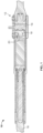
- an embodiment of the system 10 includes an implantable device 12 for implantation in a subject or patient 2, particularly a human.
- the human subject 2 may be of any age or size.
- Implantable device 12 includes one or more subcutaneous sensors 14 configured to be coupled, or coupled, to an implant 16.
- the sensor 14 may measure force, temperature, electricity, pH, distance, pressure, and biomolecules, and may transmit data including these measurements.
- the sensor 14 may measure force between 0 and 300 pounds (1.33 kN), 0 and 200 pounds (0.89 kN), 0 and 100 pounds (0.44 kN), 0 and 50 pounds (0.22 kN), or any subrange thereof.
- the sensor 14 may be, for example, capacitive, resistive, strain gauge, micromechanical, piezoelectric, or any combination thereof. Sensed data also may have a data accuracy. In the case of force, the sensor 14 may have a data accuracy of +/- 5 pounds (0.02 kN), +/- 2 pounds (0.009 kN), +/- 1 pound (0.004 kN), +/- 0.5 (0.002 kN) pound, or any subrange thereof.
- the implant 16 may be, by way of example, a spinal rod or an intramedullary rod.
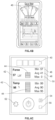
- the sensor 14 may contact a force-load coupler 18 configured to interface between the implant 16 and the sensor 14.
- the force-load coupler 18 may have a surface 19 that is shaped complementary to a contacted surface 21 of the sensor 14 where the coupler 18 and the sensor 14 interface such that the sensor 14 and the coupler 18 resist lateral movement.
- the coupler 18 may have a cam 20 integrally formed in the coupler 18 and positioned on the side of coupler 18 that is opposite from sensor 14.
- One or more thrust bearings 22 may be formed within the implant 16 and disposed on opposite sides of the cam 20 to transfer force from the implant 16 to the coupler 18 and thus to the sensor 14.
- One or more anti-backout washers 24 may be positioned between the thrust bearing 22 and the coupler 18 such that the device 12 will resist loosening when the device 12 is subjected to vibration.
- the sensor 14 is in communication with a circuit board 26, such as a printed circuit board, and the sensor 14 transmits sensed data to the circuit board 26.
- the circuit board 26 is configured to receive the sensed data from the sensor 14 and to communicate the data to a controller 28 (e.g., a microcontroller) for processing and/or temporary or permanent storage on a memory (not shown).
- the controller 28 is configured to transmit data to a transmitter 30.
- the controller 28 may be configured to lower, or eliminate power consumption, when the system 10 is not being used.
- the transmitter 30 is a tubular piezoelectric transducer.
- the transmitter 30 may be secured within the implant 16 with, for example, epoxy.
- the tubular geometry allows the piezoelectric transducer to fit in tubular implants 16, such as spinal rods and intramedullary nails. And, owing to radial mode of the vibration, the tubular transducer propagates data radially, covering 360 degrees.
- Polyimide film with silicone adhesive for example, KAPTON ® tapes
- KAPTON ® tapes may be disposed between the transmitter 30 and the implant 16 to isolate the transmitter from the implant 16.
- the circuit board 26 may include a frequency synthesizer (i.e., creates carrier waves for piezoelectric transducer 30), power amplifier and noise filters (i.e., conditions carrier wave), power and read strain gauge (i.e., force sensor controls), and may be configured to adjust carrier waves, power, etc. (such as by computer executable instructions that interface with a user via a graphical user interface, as discussed below).
- a frequency synthesizer i.e., creates carrier waves for piezoelectric transducer 30
- power amplifier and noise filters i.e., conditions carrier wave
- power and read strain gauge i.e., force sensor controls
- the transmitter 30 is configured to send and receive wireless signals, such as ultrasound sound waves carrying data, and receive power, such as from ultrasound sound waves.
- These ultrasound sound waves may be in any frequency of ultrasound, but are generally greater than about 20 kilohertz. In an embodiment, the frequency of ultrasound sound waves is between 200 and 400 kilohertz or is about 300 kilohertz.
- Benefits of utilizing ultrasound sound waves for power and/or data transmission include that ultrasound sound waves: (1) propagate through metal or solid mediums (e.g., metallic medical implants), and (2) send data transcutaneously through various human skin.
- the transmitter 30 is configured to transmit data and/or power transcutaneously (i.e., from within the subject 2 and across the skin of the subject 2 such that the data and/or power may be received externally from the subject 2). Additionally, power may be received by the transmitter 30 from external from the subject 2.
- a battery, or capacitor, 32 may be in electric communication with the transmitter 30 such that the battery 32 can store power received from the transmitter 30 and transmit stored power to the transmitter 30, the controller 28, the circuit board 26, and sensor 14.
- the circuit board 26, the controller 28, the transmitter 30, and the battery 32 may be contained in a sealed compartment 34 such that they are configured to not directly contact the subject 2 when implanted.
- the sealed compartment 34 may be advantageous to separate these components from the other parts of the implantable device 12, as these components may not be rated for direct in vivo bodily contact, in contrast with the implant 16, which is constructed from biocompatible materials.
- An ultrasound couplant may be disposed between the transmitter 30 and the sealed compartment 34, or the sealed compartment 34 and the implant 16, such that the device 12 has a single resonance frequency.
- the transmitter 30 may be configured to transmit sensed data from the sensor 14 wirelessly and transcutaneously by short-wavelength ultra high frequency radio waves in the medical radio band from about 2.4 to 2.485 GHz (i.e., BLUETOOTH ® ).
- the transmitter may be configured to have a power consumption of between 0.5 mW and 80 mW, 1 mW and 60 mW, and 2.0 mW and 40 mW, 10 mW, 5 mW, or any subrange thereof.
- the transmitter 30 may consume about 20 mW of power when in operation.
- the transmitter 30 may be configured to transmit data at least four inches (at least 101.6 mm) through water at a rate of 5 values per second (lkb/s) with a data reliability of 95%. Data reliability transmitted from the transmitter at these power levels may be at least 95%, at least 98%, at least 99%, at least 99.9%, or 100%.
- Data reliability means reliability over 10 minutes as calculated from a bit error rate (BER).
- Transmitter power may be less than 20 mW, such as less than 5 mW.
- Signal to noise may be less than 30 dB, such as 10 dB.
- a piezo phase array PPA which may utilized to focus the vibration into a specific location (for example, the implant).
- the wireless transcutaneous sensor 14 enables data, such as force, to be measured from the sensor 14 in vivo when the sensor 14 is implanted with an implant 16.
- the implant is adjustable in vivo, such as the case in magnetically adjustable implant systems, such as MAGEC ® magnetically adjustable implant systems for spinal and limb lengthening procedures sold by NuVasive, Inc. of San Diego, California.
- Such adjustable systems are disclosed in, for example, US Patent Nos. 9,398,925 and 9,393,117 .
- the system 10 may be provided in a kit for use (i.e., implantation) during spinal correction and limb lengthening surgical procedures.
- the system 10 may wirelessly transmit data sensed by the subcutaneous sensor 14 from the transmitter 30 to a receiver 36 external to the subject 2.
- Receiver output may be less than 1 mV, such as 0.2 mV.
- the receiver 36 may be wearable by the subject 2 (e.g., coupled with an article of clothing or accessory to be worn by the subject 2) or may be a computer system external and proximate to the subject 2.
- This data transmission from the transmitter 30 to the receiver 36 may be carried by ultrasound sound waves.
- the receiver 36 may receive the data transmission from the transmitter 30, and process the data to transmit the sensed data to a mobile device 38 by short-wavelength ultra high frequency radio waves in the medical radio band from about 2.4 to 2.485 GHz.
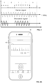
- FIG. 4 illustrates a flow chart of an embodiment of the system 10, particularly how components of an embodiment of the system 10 communicate data and/or power with each other. Wires that connect these components of the system may be shielded, such as by epoxy.
- wireless signals carrying the sensed data may be modulated for wireless transmission.
- Suitable forms of modulation include on-off keying, amplitude shift keying (ASK), frequency shift keying (FSK), phase shift keying (PSK), and analogue frequency modulation.
- ASK amplitude shift keying
- FSK frequency shift keying
- PSK phase shift keying
- analogue frequency modulation amplitude shift keying
- signals that are modulated may require less power than non-modulated signals and may be received farther away from the transmitter 30 than non-modulated signals.
- Modulated signals may also have a greater accuracy than non-modulated signals.
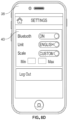
- FIGS. 6A-6C illustrate screenshots of the mobile device 38 containing computer executable instructions configured to receive, process, and display the sensed data from the subcutaneous sensor 14.
- the mobile device 38 may contain a graphical user interface (GUI) 40 that displays sensed data to users, such as patients and physicians, and allows users to control the system 10 via the computer executable instructions.
- GUI graphical user interface
- the GUI 40 may display sensed data 42 (force and temperature, as shown), and provide a graphical representation 44 of the sensed data.
- the GUI 40 may display, and the system 10 store, the maximum value 46, the average value 48, and the minimum value 50 of the sensed data.
- the GUI 40 may also be configured to allow a user to control settings 52 of the system 10, pause/start 54 the system 10, reset 56 the system 10, and power on and off 58 the system 10.
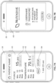
- FIGS. 7A-8D illustrate screenshots of a mobile device having computer readable instructions configured to communicate with the subcutaneous sensor 14 according to another embodiment of the system 10.
- the computer executable instructions stored on the mobile device 38 may be configured to record 60 sensed data over time for later viewing, such as by a physician.
- the computer executable instructions may indicate whether the mobile device 38 is actively communicating (i.e., connected) with the sensor 14.
- the computer readable instructions may be configured to display sensed data on the mobile device 38 in metric and/or English (i.e., imperial) units.
- the computer program may contain computer executable instructions configured to selectively limit functions or data to different types of users, such as between physicians, patients, and device service providers.
- physicians may be able to access data from multiple patients (as shown in FIG. 8A ), while the computer executable instructions are configured to restrict access to patient data by security measures, such as a password, to other types of users.
- the computer executable instructions are configured to restrict access to features that data that is desired to only be provided to device service providers by security measures, such as passwords.
- the computer executable instructions may be configured to store and allow users to individually access sensed data from different sessions in time.
- the computer executable instructions may be configured to include a sharing feature 62 such that users of the mobile device 38 may be able to share sensed data by, for example, e-mail, text message, and social media, directly through the computer executable instructions of the mobile device 38.
- the computer executable instructions may enable users to customize BLUETOOTH ® functionality (on/off) of the mobile device 38, select between English or metric units, and control the scale of the GUI 40 on the mobile device 38, including auto-scale and a custom scale.
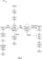
- FIG. 9 shows a flowchart of the computer readable instructions according to an embodiment of the system 10. The methods described hereinafter are not part of the claimed invention.
- the present disclosure also provides a method of transcutaneously transmitting data from the subcutaneous sensor 14 positioned within the subject 2 and/or a method of measuring data at an implant site of the subject 2.
- a method is also disclosed to determine strain in rods to predict failure, and to determine health and progress of fusion.
- a method is provided to measure an applied force using the system 10 of the present disclosure in order to control growth of bones by utilizing the Heuter Volkman principle (i.e., that bones grow faster when placed under a tensile load).
- the system 10 can be utilized to maintain an ideal compressive load on desired bones, which can be used to control bone growth in facial surgery, long bones, extremities (fingers, toes, etc.), and apex correction for scoliosis).
- the system 10 may be used in a method of distraction osteogenesis, monitor bone quality of fusion, and detect stroke or movement of the device 12.
- the system 10 may be used in connection with pharmacological agents such that if the sensors 14 that detect slower rates of bone growth or fusion below a predetermined level, a growth promoting pharmacological agent (e.g., bisphosphonates) is stored at the implant site and released locally to promote bone formation. Similarly, the sensors 14 detect inflammation or a rise in temperature, the sensors 14 could instruct the implant 16 to release a pharmacological agent locally to reduce the cause, such as an infection.
- a growth promoting pharmacological agent e.g., bisphosphonates
- a method is disclosed herein that includes measuring force in the implant 16 to determine, and monitor, patient compliant with a treatment plan (i.e., recommended levels of activities after surgery). By recording force over time, one can determine if the patent 2 is compliant with recommended activities.
- a treatment plan i.e., recommended levels of activities after surgery.
- a method is disclosed herein where the implant 16 is automatically adjusted (i.e., to increase force) if the system 10 senses that compression across a facture site is not above a predetermined level.
- a method is disclosed herein to measure force in an instrument when distracting or compressing pedicle screws across a graft in a spine of the subject 2.
- a method is disclosed herein to measure force and automatically adjust tension in sutures or tethering devices. If the force sensor 14 determines a predetermined tension has been met, the system 10 transmits instructions to the implant 16 to tighten to tension, or alerts the physician that the tension should be modified.
- a method is described herein where the system monitors intradiscal pressure to help subjects 2 to understand how to have less pressure on their discs during activities.
- the sensor 14 is disposed between discs of the subject 2.
- the methods described herein include transcutaneously transmitting wireless power (including indirectly) to the subcutaneous sensor 14, sensing data with the subcutaneous sensor 14, and transcutaneously transmitting sensed data (including indirectly) from the subcutaneous sensor 14.
- the sensed data may be received by a subcutaneous or external receiver 36.
- the data may be transmitted to the receiver 36 by ultrasound sound waves, which may be modulated.
- the receiver 36 may be configured to transmit data, including transcutaneously if internal, to the mobile device 38, such as by BLUETOOTH ® .
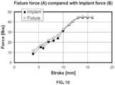
- FIG. 10 illustrates a graph comparing the predetermined force (fixture force) with the sensed force (implant force). As can be seen, the sensed force matches the fixture force +/within 3 pounds (0.013 kN). The difference between the fixture force and the sensor force can be explained by, for example, internal friction of the fixture.
- a tubular piezoelectric transducer was placed within a housing of a metal adjustable length spinal rod (i.e. tubular).
- a gap between the piezoelectric transducer and housing metal was filled with an ultrasound couplant.
- the ultrasound couplant matches the acoustic impedance between two different materials.
- the piezoelectric transducer's ability to send RF-like signal was tested and verified.
- the adjustable length spinal rod housing containing the tubular piezoelectric transducer (“Implant PT") was placed inside of a water bath in the jug, then another piezoelectric transducer was placed on the wall of the jug (the "Reader PT").
- the implant piezoelectric transducer was excited (applied with a sinusoidal voltage) and the piezoelectric transducer created a vibration, which traveled through the couplant, through the metal housing tube, through the water, through the plastic jug, and it was finally detected by the Reader PT.
- the data signal may be modulated, which advantageously, significantly reduces the size of the energy storage device needed. See, for example, FIG. 11B .
- Electrical signal was applied to the reader piezoelectric transducer 30, which is converted into vibration.
- the frequency used was the structural resonant frequency of the implant magnet, which forces the vibration to remain even after the driving force is removed.
- the driving signal stopped after a few square waves, which is enough to drive the implant piezoelectric transducer 30 to resonate, the implant signal was tailing down. The tail end of this signal can be modulated to, and sent back to, the reader piezoelectric transducer 30.
Landscapes
- Health & Medical Sciences (AREA)
- Life Sciences & Earth Sciences (AREA)
- Engineering & Computer Science (AREA)
- Medical Informatics (AREA)
- Surgery (AREA)
- Veterinary Medicine (AREA)
- Biophysics (AREA)
- Pathology (AREA)
- Biomedical Technology (AREA)
- Heart & Thoracic Surgery (AREA)
- Public Health (AREA)
- Molecular Biology (AREA)
- Physics & Mathematics (AREA)
- Animal Behavior & Ethology (AREA)
- General Health & Medical Sciences (AREA)
- Computer Networks & Wireless Communication (AREA)
- Physiology (AREA)
- Human Computer Interaction (AREA)
- Power Engineering (AREA)
- Transplantation (AREA)
- Measuring And Recording Apparatus For Diagnosis (AREA)
- Prostheses (AREA)
- Ultra Sonic Daignosis Equipment (AREA)
Claims (8)
- System (10), umfassend:ein Implantat (16), welches eine longitudinale Achse aufweist und dazu eingerichtet ist, in einem Subjekt implantiert zu sein; undeine implantierbare Vorrichtung (12) zum Erfassen von Daten, wobei die implantierbare Vorrichtung (12) umfasst:
einen subkutanen Sensor (14), welcher dazu eingerichtet ist, mit dem Implantat (16) gekoppelt zu sein und Daten zu erfassen, eine Leiterplatte (26), eine Steuereinrichtung (28) und einen Sender (30), welcher dazu eingerichtet ist, durch den subkutanen Sensor (14) erfasste Daten unter Verwendung eines Ultraschalldatensignals drahtlos und transkutan zu übertragen,dadurch gekennzeichnet, dass der subkutane Sensor (14) dazu eingerichtet ist, die erfassten Daten an die Leiterplatte (26) zu übertragen, die Leiterplatte (26) dazu eingerichtet ist, durch den subkutanen Sensor (14) erfasste Daten zu empfangen und die erfassten Daten für wenigstens eines aus einem Verarbeiten und einer Speicherung an die Steuereinrichtung (28) zu kommunizieren, und die Steuereinrichtung (28) dazu eingerichtet ist, die erfassten Daten an den Sender (30) zu übertragen,und dass der Sender (30) ein röhrenförmiger piezoelektrischer Wandler ist, welcher mit seiner longitudinalen Achse sich entlang der longitudinalen Achse des Implantats (16) erstreckend angeordnet ist und dazu eingerichtet ist, Daten, welche radial 360 Grad abdecken, an einen Empfänger weiterzugeben, welcher sich außerhalb eines Subjekts befindet, in welchem das System (10) positioniert ist. - System (10) nach Anspruch 1, wobei die implantierbare Vorrichtung (12) dazu eingerichtet ist, betriebsmäßig Energie aus Ultraschallwellen zu empfangen und dem subkutanen Sensor (14) Energie bereitzustellen.
- System (10) nach Anspruch 2, wobei die Ultraschallwellen eine Frequenz von mehr als etwa 20 Kilohertz aufweisen.
- System (10) nach Anspruch 1, wobei der röhrenförmige piezoelektrische Wandler (30) in Kommunikation mit dem subkutanen Sensor (14) ist.
- System (10) nach Anspruch 1, wobei der röhrenförmige piezoelektrische Wandler (30) dazu eigerichtet ist, Energie durch Ultraschallwellen transkutan zu empfangen und durch den subkutanen Sensor (14) erfasste Daten durch Ultraschallwellen drahtlos und transkutan zu übertragen.
- System (10) nach Anspruch 1, ferner umfassend eine Kraft-Last-Kopplungseinrichtung (18), welche dazu eingerichtet ist, eine Schnittstelle zwischen dem Implantat (16) und dem subkutanen Sensor (14) zu bilden.
- System (10) nach Anspruch 1, wobei die drahtlos übertragenen erfassten Daten durch kurzwellige Ultrahochfrequenz-Funkwellen in dem medizinischen Funkband von etwa 2,4 bis 2,485 GHz übertragen werden.
- System (10) nach Anspruch 1, wobei das Implantat (16) ausgewählt ist aus der Gruppe, bestehend aus: einem Spinalstab, einem intramedullären Stab und einem Dornfortsatzabstandshalter.
Priority Applications (1)
| Application Number | Priority Date | Filing Date | Title |
|---|---|---|---|
| EP23216245.3A EP4318173A3 (de) | 2016-07-18 | 2017-07-18 | Kommunikationsvorrichtung und -verfahren |
Applications Claiming Priority (2)
| Application Number | Priority Date | Filing Date | Title |
|---|---|---|---|
| US201662363340P | 2016-07-18 | 2016-07-18 | |
| PCT/US2017/042634 WO2018017591A1 (en) | 2016-07-18 | 2017-07-18 | Communication device and methods |
Related Child Applications (1)
| Application Number | Title | Priority Date | Filing Date |
|---|---|---|---|
| EP23216245.3A Division EP4318173A3 (de) | 2016-07-18 | 2017-07-18 | Kommunikationsvorrichtung und -verfahren |
Publications (4)
| Publication Number | Publication Date |
|---|---|
| EP3484352A1 EP3484352A1 (de) | 2019-05-22 |
| EP3484352A4 EP3484352A4 (de) | 2020-02-19 |
| EP3484352B1 true EP3484352B1 (de) | 2024-01-03 |
| EP3484352C0 EP3484352C0 (de) | 2024-01-03 |
Family
ID=60996109
Family Applications (2)
| Application Number | Title | Priority Date | Filing Date |
|---|---|---|---|
| EP23216245.3A Withdrawn EP4318173A3 (de) | 2016-07-18 | 2017-07-18 | Kommunikationsvorrichtung und -verfahren |
| EP17831704.6A Active EP3484352B1 (de) | 2016-07-18 | 2017-07-18 | System umfassend ein implantat und ein implantierbares gerät zur transkutanen datenübertragung |
Family Applications Before (1)
| Application Number | Title | Priority Date | Filing Date |
|---|---|---|---|
| EP23216245.3A Withdrawn EP4318173A3 (de) | 2016-07-18 | 2017-07-18 | Kommunikationsvorrichtung und -verfahren |
Country Status (6)
| Country | Link |
|---|---|
| US (2) | US11389111B2 (de) |
| EP (2) | EP4318173A3 (de) |
| JP (1) | JP7150698B2 (de) |
| CN (1) | CN109688902A (de) |
| AU (1) | AU2017300384B2 (de) |
| WO (1) | WO2018017591A1 (de) |
Families Citing this family (19)
| Publication number | Priority date | Publication date | Assignee | Title |
|---|---|---|---|---|
| EP4318173A3 (de) * | 2016-07-18 | 2024-04-24 | NuVasive Specialized Orthopedics, Inc. | Kommunikationsvorrichtung und -verfahren |
| US10980419B2 (en) * | 2016-11-07 | 2021-04-20 | Orthodx Inc | Systems and methods for monitoring implantable devices for detection of implant failure utilizing wireless in vivo micro sensors |
| CN118436321A (zh) | 2018-04-19 | 2024-08-06 | 艾奧塔生物科技公司 | 使用用于神经感测和刺激的超声通信的植入物 |
| IL312444B2 (en) | 2018-04-19 | 2025-05-01 | Iota Biosciences Inc | Implants that use ultrasonic communication to regulate splenic neural activity |
| BR112021003792A2 (pt) | 2018-08-29 | 2021-05-18 | Iota Biosciences, Inc. | dispositivo de neuromodulação em circuito fechado implantável, sistemas e métodos de uso |
| WO2020160498A1 (en) * | 2019-01-31 | 2020-08-06 | The University Of Chicago | Bionic breast |
| WO2020163792A1 (en) * | 2019-02-07 | 2020-08-13 | 171Nuvasive Specialized Orthopedics, Inc. | Ultrasonic communication in medical devices |
| US11458363B2 (en) * | 2019-06-17 | 2022-10-04 | Rehab2Fit Technologies, Inc. | System and method for intelligent self-calibration of target load thresholds for users of exercise machines |
| MX2022004584A (es) | 2019-10-17 | 2022-09-26 | Iota Biosciences Inc | Dispositivos y métodos para modular la actividad del sistema inmunitario en un paciente con cáncer y tratamiento del cáncer. |
| CN111938881B (zh) * | 2020-08-20 | 2023-02-28 | 四川大学华西医院 | 可监测活动姿态及其应力的智能椎间盘系统及监测方法 |
| EP4297674A1 (de) | 2021-02-23 | 2024-01-03 | NuVasive Specialized Orthopedics, Inc. | Einstellbares implantat, system und verfahren |
| WO2022204096A1 (en) * | 2021-03-24 | 2022-09-29 | Smith & Nephew, Inc. | Implantable motorized bone adjustment devices |
| US11857346B2 (en) * | 2021-05-25 | 2024-01-02 | Warsaw Orthopedic, Inc. | Systems and methods for real-time monitoring of bone correction |
| AU2021463042A1 (en) | 2021-08-31 | 2024-03-07 | Nuvasive, Inc. | Rod reduction instrument feedback system |
| US11723692B1 (en) * | 2022-02-01 | 2023-08-15 | Bala Sundararajan | Smart and autonomous growing rod for treating spinal deformities |
| US20230293302A1 (en) * | 2022-03-16 | 2023-09-21 | Boston Scientific Scimed, Inc. | Electronic implantable penile prosthesis with remote activation |
| US12458417B2 (en) | 2022-08-15 | 2025-11-04 | Nuvasive Specialized Orthopedics Inc. | Intermedullary lengthening implant with integrated load sensor |
| US12533164B2 (en) | 2023-05-03 | 2026-01-27 | Nuvasive Specialized Orthopedics, Inc. | Adjustable implant |
| US20250099038A1 (en) * | 2023-09-25 | 2025-03-27 | Orthosensor, Inc. | Devices, systems, and methods for controlling implantable sensors |
Citations (1)
| Publication number | Priority date | Publication date | Assignee | Title |
|---|---|---|---|---|
| WO2015031853A2 (en) * | 2013-08-29 | 2015-03-05 | Battelle Memorial Institute | Acoustic transmission devices and process for making and using same |
Family Cites Families (42)
| Publication number | Priority date | Publication date | Assignee | Title |
|---|---|---|---|---|
| US5240004A (en) * | 1989-04-28 | 1993-08-31 | Thomas Jefferson University | Intravascular, ultrasonic imaging catheters and methods for making same |
| US5833603A (en) | 1996-03-13 | 1998-11-10 | Lipomatrix, Inc. | Implantable biosensing transponder |
| US6558320B1 (en) | 2000-01-20 | 2003-05-06 | Medtronic Minimed, Inc. | Handheld personal data assistant (PDA) with a medical device and method of using the same |
| US6468219B1 (en) * | 2000-04-24 | 2002-10-22 | Philip Chidi Njemanze | Implantable telemetric transcranial doppler device |
| US6636769B2 (en) * | 2000-12-18 | 2003-10-21 | Biosense, Inc. | Telemetric medical system and method |
| JP3962250B2 (ja) * | 2001-08-29 | 2007-08-22 | 株式会社レアメタル | 生体内情報検出システム及びこれに用いるタグ装置、中継装置 |
| US8974446B2 (en) * | 2001-10-11 | 2015-03-10 | St. Jude Medical, Inc. | Ultrasound ablation apparatus with discrete staggered ablation zones |
| US8176922B2 (en) * | 2004-06-29 | 2012-05-15 | Depuy Products, Inc. | System and method for bidirectional communication with an implantable medical device using an implant component as an antenna |
| US7955357B2 (en) | 2004-07-02 | 2011-06-07 | Ellipse Technologies, Inc. | Expandable rod system to treat scoliosis and method of using the same |
| EP1861007A2 (de) * | 2005-01-18 | 2007-12-05 | Koninklijke Philips Electronics N.V. | Elektronisch steuerbare einnahmekapsel zur probenentnahme von flüssigkeiten im verdauungstrakt |
| US20110213221A1 (en) * | 2005-03-29 | 2011-09-01 | Roche Martin W | Method for Detecting Body Parameters |
| US8486070B2 (en) * | 2005-08-23 | 2013-07-16 | Smith & Nephew, Inc. | Telemetric orthopaedic implant |
| US7517315B2 (en) * | 2005-08-26 | 2009-04-14 | Boston Scientific Scimed, Inc. | System and method for determining the proximity between a medical probe and a tissue surface |
| WO2008039116A1 (en) * | 2006-09-28 | 2008-04-03 | St. Jude Medical Ab | Medical implantable piezoelectric sensor and method for manufacturing the same |
| US8108030B2 (en) | 2006-10-20 | 2012-01-31 | Board Of Regents, The University Of Texas System | Method and apparatus to identify vulnerable plaques with thermal wave imaging of heated nanoparticles |
| US7901360B1 (en) * | 2007-05-17 | 2011-03-08 | Pacesetter, Inc. | Implantable sensor for measuring physiologic information |
| US20090005708A1 (en) | 2007-06-29 | 2009-01-01 | Johanson Norman A | Orthopaedic Implant Load Sensor And Method Of Interpreting The Same |
| US7998089B2 (en) * | 2007-11-08 | 2011-08-16 | Radi Medical Systems Ab | Method of making a guide wire based assembly and reusing an energy source |
| EP3708219B1 (de) * | 2008-05-15 | 2022-08-03 | Inspire Medical Systems, Inc. | Vorrichtung zur erfassung des beatmungsdrucks in einem implantierbaren stimulationssystem |
| JP2012507340A (ja) | 2008-10-31 | 2012-03-29 | ミルックス・ホールディング・エスエイ | エネルギーの無線伝送を使用して骨調節を操作するためのデバイスおよび方法 |
| EP2208458A1 (de) * | 2009-01-14 | 2010-07-21 | Roche Diagnostics GmbH | Medizinisches Überwachungsnetzwerk |
| US8506495B2 (en) * | 2009-06-10 | 2013-08-13 | Cardiac Pacemakers, Inc. | Implantable medical devices with piezoelectric anchoring member |
| US8421479B2 (en) | 2009-06-30 | 2013-04-16 | Navisense | Pulsed echo propagation device and method for measuring a parameter |
| CN101800486B (zh) * | 2010-02-25 | 2012-07-04 | 上海交通大学 | 基于超声供能的共振式可植入微能源装置 |
| CN101856222A (zh) * | 2010-05-21 | 2010-10-13 | 上海锐灵电子科技有限公司 | 植入式无线电子检测装置 |
| WO2012112396A2 (en) | 2011-02-14 | 2012-08-23 | Ellipse Technologies, Inc. | Device and method for treating fractured bones |
| CN103945763B (zh) | 2011-09-23 | 2016-04-06 | 奥索传感器公司 | 用于椎骨负载和位置感测的系统和方法 |
| US8974366B1 (en) | 2012-01-10 | 2015-03-10 | Piezo Energy Technologies, LLC | High power ultrasound wireless transcutaneous energy transfer (US-TET) source |
| WO2013138275A1 (en) * | 2012-03-12 | 2013-09-19 | University Of South Florida | Implantable biocompatible sic sensors |
| AU2014230252B2 (en) * | 2013-03-15 | 2018-11-29 | Implantica Patent Ltd. | Operable implant comprising an electrical motor and a gear system |
| US9544068B2 (en) * | 2013-05-13 | 2017-01-10 | The Board Of Trustees Of The Leland Stanford Junior University | Hybrid communication system for implantable devices and ultra-low power sensors |
| US10033470B2 (en) * | 2013-08-29 | 2018-07-24 | Battelle Memorial Institute | Acoustic transmission devices and process for making and using same |
| US9901269B2 (en) * | 2014-04-17 | 2018-02-27 | Branchpoint Technologies, Inc. | Wireless intracranial monitoring system |
| US10448832B2 (en) * | 2014-11-06 | 2019-10-22 | International Business Machines Corporation | Acoustic computing systems for implant and dermal data communication, power supply and energy storage |
| US11139899B2 (en) * | 2015-05-26 | 2021-10-05 | The Board Of Trustees Of The University Of Illinois | Method and apparatus for ultra high bandwidth acoustic communication and power transfer |
| CN204992728U (zh) * | 2015-10-13 | 2016-01-20 | 盐城工学院 | 一种超声波无线充电装置 |
| US20170105635A1 (en) * | 2015-10-16 | 2017-04-20 | Medtronic, Inc. | Intracardiac medical device with pressure sensing |
| US10667904B2 (en) * | 2016-03-08 | 2020-06-02 | Edwards Lifesciences Corporation | Valve implant with integrated sensor and transmitter |
| US11191479B2 (en) * | 2016-03-23 | 2021-12-07 | Canary Medical Inc. | Implantable reporting processor for an alert implant |
| US10252066B2 (en) * | 2016-05-05 | 2019-04-09 | Piezo Energy Technologies Llc | Miniaturized wireless ultrasound energy transfer system for powering a bio-implantable medical device |
| JP6603423B2 (ja) * | 2016-05-24 | 2019-11-06 | シナジア メディカル | 埋め込み型医療装置に対して外部要素を位置合わせするためのセンタリングキットおよび対応する方法 |
| EP4318173A3 (de) * | 2016-07-18 | 2024-04-24 | NuVasive Specialized Orthopedics, Inc. | Kommunikationsvorrichtung und -verfahren |
-
2017
- 2017-07-18 EP EP23216245.3A patent/EP4318173A3/de not_active Withdrawn
- 2017-07-18 WO PCT/US2017/042634 patent/WO2018017591A1/en not_active Ceased
- 2017-07-18 AU AU2017300384A patent/AU2017300384B2/en not_active Ceased
- 2017-07-18 EP EP17831704.6A patent/EP3484352B1/de active Active
- 2017-07-18 JP JP2019502164A patent/JP7150698B2/ja active Active
- 2017-07-18 CN CN201780054733.5A patent/CN109688902A/zh active Pending
-
2019
- 2019-01-17 US US16/250,618 patent/US11389111B2/en active Active
-
2022
- 2022-05-11 US US17/741,656 patent/US20220265213A1/en active Pending
Patent Citations (1)
| Publication number | Priority date | Publication date | Assignee | Title |
|---|---|---|---|---|
| WO2015031853A2 (en) * | 2013-08-29 | 2015-03-05 | Battelle Memorial Institute | Acoustic transmission devices and process for making and using same |
Non-Patent Citations (3)
| Title |
|---|
| LI H ET AL: "Piezoelectric transducer design for a miniaturized injectable acoustic transmitter", SMART MATERIALS AND STRUCTURES, IOP PUBLISHING LTD., BRISTOL, GB, vol. 24, no. 11, 7 October 2015 (2015-10-07), pages 115010, XP020291283, ISSN: 0964-1726, [retrieved on 20151007], DOI: 10.1088/0964-1726/24/11/115010 * |
| ROHLMANN A ET AL: "A spinal fixation device for in vivo load measurement", JOURNAL OF BIOMECHANICS, PERGAMON PRESS, NEW YORK, NY, US, vol. 27, no. 7, 1 July 1994 (1994-07-01), pages 961 - 963, 965, XP026264594, ISSN: 0021-9290, [retrieved on 19940701], DOI: 10.1016/0021-9290(94)90268-2 * |
| ROHLMANN ET AL: "An instrumented implant for vertebral body replacement that measures loads in the anterior spinal column", MEDICAL ENGINEERING & PHYSICS, BUTTERWORTH-HEINEMANN, GB, vol. 29, no. 5, 5 March 2007 (2007-03-05), pages 580 - 585, XP005912927, ISSN: 1350-4533, DOI: 10.1016/J.MEDENGPHY.2006.06.012 * |
Also Published As
| Publication number | Publication date |
|---|---|
| EP4318173A2 (de) | 2024-02-07 |
| JP7150698B2 (ja) | 2022-10-11 |
| EP3484352A4 (de) | 2020-02-19 |
| WO2018017591A1 (en) | 2018-01-25 |
| WO2018017591A9 (en) | 2018-04-05 |
| US20220265213A1 (en) | 2022-08-25 |
| US20190150835A1 (en) | 2019-05-23 |
| US11389111B2 (en) | 2022-07-19 |
| AU2017300384B2 (en) | 2022-02-03 |
| EP3484352A1 (de) | 2019-05-22 |
| EP4318173A3 (de) | 2024-04-24 |
| JP2019522548A (ja) | 2019-08-15 |
| AU2017300384A1 (en) | 2019-02-21 |
| CN109688902A (zh) | 2019-04-26 |
| EP3484352C0 (de) | 2024-01-03 |
Similar Documents
| Publication | Publication Date | Title |
|---|---|---|
| US20220265213A1 (en) | Communication device and methods | |
| JP5771199B2 (ja) | 医療用インプラント、診断装置又は生物学的手法をモニタリング及び/又は制御するための測定信号を、処理及び伝送するための装置 | |
| JP4657713B2 (ja) | ひずみ検知システム | |
| US6034296A (en) | Implantable bone strain telemetry sensing system and method | |
| JP4977020B2 (ja) | 歪モニタリングシステム及び装置 | |
| CA2712893C (en) | System and method for communicating with an implant | |
| JP4904338B2 (ja) | ハイブリッド電磁超音波式末端ターゲティングシステム | |
| KR20210015791A (ko) | 신경 감지 및 자극을 위해 초음파 통신을 사용하는 이식물 | |
| CN113518640A (zh) | 使用超声波供电的可植入设备的电力控制 | |
| KR20250134003A (ko) | 경보 임플란트를 위한 이식 가능한 리포팅 프로세서 | |
| WO2022035889A1 (en) | Ultrasonic implant and system for measurement of intraocular pressure | |
| Zou et al. | Wireless interrogation of implantable SAW sensors | |
| US20250359911A1 (en) | Medical device for implanting in boney tissue and characterization of bone fractures | |
| WO2020163792A1 (en) | Ultrasonic communication in medical devices | |
| AU2018374527A1 (en) | Implantable distraction device | |
| US20260026751A1 (en) | Implantable medical device for cardiac monitoring using sound | |
| JP2025535081A (ja) | 脊椎の移植可能なセンサーアセンブリ |
Legal Events
| Date | Code | Title | Description |
|---|---|---|---|
| STAA | Information on the status of an ep patent application or granted ep patent |
Free format text: STATUS: THE INTERNATIONAL PUBLICATION HAS BEEN MADE |
|
| PUAI | Public reference made under article 153(3) epc to a published international application that has entered the european phase |
Free format text: ORIGINAL CODE: 0009012 |
|
| STAA | Information on the status of an ep patent application or granted ep patent |
Free format text: STATUS: REQUEST FOR EXAMINATION WAS MADE |
|
| 17P | Request for examination filed |
Effective date: 20190117 |
|
| AK | Designated contracting states |
Kind code of ref document: A1 Designated state(s): AL AT BE BG CH CY CZ DE DK EE ES FI FR GB GR HR HU IE IS IT LI LT LU LV MC MK MT NL NO PL PT RO RS SE SI SK SM TR |
|
| AX | Request for extension of the european patent |
Extension state: BA ME |
|
| DAV | Request for validation of the european patent (deleted) | ||
| DAX | Request for extension of the european patent (deleted) | ||
| A4 | Supplementary search report drawn up and despatched |
Effective date: 20200117 |
|
| RIC1 | Information provided on ipc code assigned before grant |
Ipc: A61B 17/66 20060101ALI20200113BHEP Ipc: G05G 7/02 20060101ALI20200113BHEP Ipc: A61B 5/00 20060101AFI20200113BHEP Ipc: A61B 17/72 20060101ALI20200113BHEP Ipc: A61B 5/103 20060101ALI20200113BHEP Ipc: A61B 5/05 20060101ALI20200113BHEP Ipc: A61B 17/68 20060101ALI20200113BHEP |
|
| STAA | Information on the status of an ep patent application or granted ep patent |
Free format text: STATUS: EXAMINATION IS IN PROGRESS |
|
| 17Q | First examination report despatched |
Effective date: 20210421 |
|
| GRAP | Despatch of communication of intention to grant a patent |
Free format text: ORIGINAL CODE: EPIDOSNIGR1 |
|
| STAA | Information on the status of an ep patent application or granted ep patent |
Free format text: STATUS: GRANT OF PATENT IS INTENDED |
|
| INTG | Intention to grant announced |
Effective date: 20230728 |
|
| GRAS | Grant fee paid |
Free format text: ORIGINAL CODE: EPIDOSNIGR3 |
|
| GRAA | (expected) grant |
Free format text: ORIGINAL CODE: 0009210 |
|
| STAA | Information on the status of an ep patent application or granted ep patent |
Free format text: STATUS: THE PATENT HAS BEEN GRANTED |
|
| AK | Designated contracting states |
Kind code of ref document: B1 Designated state(s): AL AT BE BG CH CY CZ DE DK EE ES FI FR GB GR HR HU IE IS IT LI LT LU LV MC MK MT NL NO PL PT RO RS SE SI SK SM TR |
|
| REG | Reference to a national code |
Ref country code: GB Ref legal event code: FG4D |
|
| REG | Reference to a national code |
Ref country code: CH Ref legal event code: EP |
|
| REG | Reference to a national code |
Ref country code: DE Ref legal event code: R096 Ref document number: 602017078175 Country of ref document: DE |
|
| REG | Reference to a national code |
Ref country code: IE Ref legal event code: FG4D |
|
| U01 | Request for unitary effect filed |
Effective date: 20240122 |
|
| U07 | Unitary effect registered |
Designated state(s): AT BE BG DE DK EE FI FR IT LT LU LV MT NL PT SE SI Effective date: 20240129 |
|
| PG25 | Lapsed in a contracting state [announced via postgrant information from national office to epo] |
Ref country code: IS Free format text: LAPSE BECAUSE OF FAILURE TO SUBMIT A TRANSLATION OF THE DESCRIPTION OR TO PAY THE FEE WITHIN THE PRESCRIBED TIME-LIMIT Effective date: 20240503 |
|
| PG25 | Lapsed in a contracting state [announced via postgrant information from national office to epo] |
Ref country code: GR Free format text: LAPSE BECAUSE OF FAILURE TO SUBMIT A TRANSLATION OF THE DESCRIPTION OR TO PAY THE FEE WITHIN THE PRESCRIBED TIME-LIMIT Effective date: 20240404 |
|
| PG25 | Lapsed in a contracting state [announced via postgrant information from national office to epo] |
Ref country code: RS Free format text: LAPSE BECAUSE OF FAILURE TO SUBMIT A TRANSLATION OF THE DESCRIPTION OR TO PAY THE FEE WITHIN THE PRESCRIBED TIME-LIMIT Effective date: 20240403 Ref country code: HR Free format text: LAPSE BECAUSE OF FAILURE TO SUBMIT A TRANSLATION OF THE DESCRIPTION OR TO PAY THE FEE WITHIN THE PRESCRIBED TIME-LIMIT Effective date: 20240103 |
|
| PG25 | Lapsed in a contracting state [announced via postgrant information from national office to epo] |
Ref country code: ES Free format text: LAPSE BECAUSE OF FAILURE TO SUBMIT A TRANSLATION OF THE DESCRIPTION OR TO PAY THE FEE WITHIN THE PRESCRIBED TIME-LIMIT Effective date: 20240103 |
|
| PG25 | Lapsed in a contracting state [announced via postgrant information from national office to epo] |
Ref country code: CZ Free format text: LAPSE BECAUSE OF FAILURE TO SUBMIT A TRANSLATION OF THE DESCRIPTION OR TO PAY THE FEE WITHIN THE PRESCRIBED TIME-LIMIT Effective date: 20240103 |
|
| PG25 | Lapsed in a contracting state [announced via postgrant information from national office to epo] |
Ref country code: RS Free format text: LAPSE BECAUSE OF FAILURE TO SUBMIT A TRANSLATION OF THE DESCRIPTION OR TO PAY THE FEE WITHIN THE PRESCRIBED TIME-LIMIT Effective date: 20240403 Ref country code: NO Free format text: LAPSE BECAUSE OF FAILURE TO SUBMIT A TRANSLATION OF THE DESCRIPTION OR TO PAY THE FEE WITHIN THE PRESCRIBED TIME-LIMIT Effective date: 20240403 Ref country code: IS Free format text: LAPSE BECAUSE OF FAILURE TO SUBMIT A TRANSLATION OF THE DESCRIPTION OR TO PAY THE FEE WITHIN THE PRESCRIBED TIME-LIMIT Effective date: 20240503 Ref country code: HR Free format text: LAPSE BECAUSE OF FAILURE TO SUBMIT A TRANSLATION OF THE DESCRIPTION OR TO PAY THE FEE WITHIN THE PRESCRIBED TIME-LIMIT Effective date: 20240103 Ref country code: GR Free format text: LAPSE BECAUSE OF FAILURE TO SUBMIT A TRANSLATION OF THE DESCRIPTION OR TO PAY THE FEE WITHIN THE PRESCRIBED TIME-LIMIT Effective date: 20240404 Ref country code: ES Free format text: LAPSE BECAUSE OF FAILURE TO SUBMIT A TRANSLATION OF THE DESCRIPTION OR TO PAY THE FEE WITHIN THE PRESCRIBED TIME-LIMIT Effective date: 20240103 Ref country code: CZ Free format text: LAPSE BECAUSE OF FAILURE TO SUBMIT A TRANSLATION OF THE DESCRIPTION OR TO PAY THE FEE WITHIN THE PRESCRIBED TIME-LIMIT Effective date: 20240103 |
|
| PG25 | Lapsed in a contracting state [announced via postgrant information from national office to epo] |
Ref country code: PL Free format text: LAPSE BECAUSE OF FAILURE TO SUBMIT A TRANSLATION OF THE DESCRIPTION OR TO PAY THE FEE WITHIN THE PRESCRIBED TIME-LIMIT Effective date: 20240103 |
|
| PG25 | Lapsed in a contracting state [announced via postgrant information from national office to epo] |
Ref country code: PL Free format text: LAPSE BECAUSE OF FAILURE TO SUBMIT A TRANSLATION OF THE DESCRIPTION OR TO PAY THE FEE WITHIN THE PRESCRIBED TIME-LIMIT Effective date: 20240103 |
|
| REG | Reference to a national code |
Ref country code: DE Ref legal event code: R097 Ref document number: 602017078175 Country of ref document: DE |
|
| PG25 | Lapsed in a contracting state [announced via postgrant information from national office to epo] |
Ref country code: SM Free format text: LAPSE BECAUSE OF FAILURE TO SUBMIT A TRANSLATION OF THE DESCRIPTION OR TO PAY THE FEE WITHIN THE PRESCRIBED TIME-LIMIT Effective date: 20240103 |
|
| PG25 | Lapsed in a contracting state [announced via postgrant information from national office to epo] |
Ref country code: SK Free format text: LAPSE BECAUSE OF FAILURE TO SUBMIT A TRANSLATION OF THE DESCRIPTION OR TO PAY THE FEE WITHIN THE PRESCRIBED TIME-LIMIT Effective date: 20240103 |
|
| U21 | Renewal fee for the european patent with unitary effect paid with additional fee |
Year of fee payment: 8 Effective date: 20240920 |
|
| PG25 | Lapsed in a contracting state [announced via postgrant information from national office to epo] |
Ref country code: SM Free format text: LAPSE BECAUSE OF FAILURE TO SUBMIT A TRANSLATION OF THE DESCRIPTION OR TO PAY THE FEE WITHIN THE PRESCRIBED TIME-LIMIT Effective date: 20240103 Ref country code: SK Free format text: LAPSE BECAUSE OF FAILURE TO SUBMIT A TRANSLATION OF THE DESCRIPTION OR TO PAY THE FEE WITHIN THE PRESCRIBED TIME-LIMIT Effective date: 20240103 Ref country code: RO Free format text: LAPSE BECAUSE OF FAILURE TO SUBMIT A TRANSLATION OF THE DESCRIPTION OR TO PAY THE FEE WITHIN THE PRESCRIBED TIME-LIMIT Effective date: 20240103 |
|
| PLBE | No opposition filed within time limit |
Free format text: ORIGINAL CODE: 0009261 |
|
| STAA | Information on the status of an ep patent application or granted ep patent |
Free format text: STATUS: NO OPPOSITION FILED WITHIN TIME LIMIT |
|
| 26N | No opposition filed |
Effective date: 20241007 |
|
| PG25 | Lapsed in a contracting state [announced via postgrant information from national office to epo] |
Ref country code: MC Free format text: LAPSE BECAUSE OF FAILURE TO SUBMIT A TRANSLATION OF THE DESCRIPTION OR TO PAY THE FEE WITHIN THE PRESCRIBED TIME-LIMIT Effective date: 20240103 |
|
| REG | Reference to a national code |
Ref country code: CH Ref legal event code: PL |
|
| PG25 | Lapsed in a contracting state [announced via postgrant information from national office to epo] |
Ref country code: CH Free format text: LAPSE BECAUSE OF NON-PAYMENT OF DUE FEES Effective date: 20240731 |
|
| PGFP | Annual fee paid to national office [announced via postgrant information from national office to epo] |
Ref country code: GB Payment date: 20250529 Year of fee payment: 9 |
|
| U20 | Renewal fee for the european patent with unitary effect paid |
Year of fee payment: 9 Effective date: 20250606 |
|
| PG25 | Lapsed in a contracting state [announced via postgrant information from national office to epo] |
Ref country code: IE Free format text: LAPSE BECAUSE OF NON-PAYMENT OF DUE FEES Effective date: 20240718 |
|
| PG25 | Lapsed in a contracting state [announced via postgrant information from national office to epo] |
Ref country code: CY Free format text: LAPSE BECAUSE OF FAILURE TO SUBMIT A TRANSLATION OF THE DESCRIPTION OR TO PAY THE FEE WITHIN THE PRESCRIBED TIME-LIMIT; INVALID AB INITIO Effective date: 20170718 |
|
| PG25 | Lapsed in a contracting state [announced via postgrant information from national office to epo] |
Ref country code: HU Free format text: LAPSE BECAUSE OF FAILURE TO SUBMIT A TRANSLATION OF THE DESCRIPTION OR TO PAY THE FEE WITHIN THE PRESCRIBED TIME-LIMIT; INVALID AB INITIO Effective date: 20170718 |