EP3487645B1 - Procédé de fabrication d'un outil d'usinage de métaux - Google Patents
Procédé de fabrication d'un outil d'usinage de métaux Download PDFInfo
- Publication number
- EP3487645B1 EP3487645B1 EP17735391.9A EP17735391A EP3487645B1 EP 3487645 B1 EP3487645 B1 EP 3487645B1 EP 17735391 A EP17735391 A EP 17735391A EP 3487645 B1 EP3487645 B1 EP 3487645B1
- Authority
- EP
- European Patent Office
- Prior art keywords
- plastic
- layer
- area
- region
- base body
- Prior art date
- Legal status (The legal status is an assumption and is not a legal conclusion. Google has not performed a legal analysis and makes no representation as to the accuracy of the status listed.)
- Active
Links
Images



Classifications
-
- B—PERFORMING OPERATIONS; TRANSPORTING
- B29—WORKING OF PLASTICS; WORKING OF SUBSTANCES IN A PLASTIC STATE IN GENERAL
- B29C—SHAPING OR JOINING OF PLASTICS; SHAPING OF MATERIAL IN A PLASTIC STATE, NOT OTHERWISE PROVIDED FOR; AFTER-TREATMENT OF THE SHAPED PRODUCTS, e.g. REPAIRING
- B29C39/00—Shaping by casting, i.e. introducing the moulding material into a mould or between confining surfaces without significant moulding pressure; Apparatus therefor
- B29C39/02—Shaping by casting, i.e. introducing the moulding material into a mould or between confining surfaces without significant moulding pressure; Apparatus therefor for making articles of definite length, i.e. discrete articles
- B29C39/021—Shaping by casting, i.e. introducing the moulding material into a mould or between confining surfaces without significant moulding pressure; Apparatus therefor for making articles of definite length, i.e. discrete articles by casting in several steps
-
- B—PERFORMING OPERATIONS; TRANSPORTING
- B21—MECHANICAL METAL-WORKING WITHOUT ESSENTIALLY REMOVING MATERIAL; PUNCHING METAL
- B21D—WORKING OR PROCESSING OF SHEET METAL OR METAL TUBES, RODS OR PROFILES WITHOUT ESSENTIALLY REMOVING MATERIAL; PUNCHING METAL
- B21D37/00—Tools as parts of machines covered by this subclass
- B21D37/01—Selection of materials
-
- B—PERFORMING OPERATIONS; TRANSPORTING
- B21—MECHANICAL METAL-WORKING WITHOUT ESSENTIALLY REMOVING MATERIAL; PUNCHING METAL
- B21D—WORKING OR PROCESSING OF SHEET METAL OR METAL TUBES, RODS OR PROFILES WITHOUT ESSENTIALLY REMOVING MATERIAL; PUNCHING METAL
- B21D37/00—Tools as parts of machines covered by this subclass
- B21D37/20—Making tools by operations not covered by a single other subclass
-
- B—PERFORMING OPERATIONS; TRANSPORTING
- B23—MACHINE TOOLS; METAL-WORKING NOT OTHERWISE PROVIDED FOR
- B23P—METAL-WORKING NOT OTHERWISE PROVIDED FOR; COMBINED OPERATIONS; UNIVERSAL MACHINE TOOLS
- B23P15/00—Making specific metal objects by operations not covered by a single other subclass or a group in this subclass
- B23P15/24—Making specific metal objects by operations not covered by a single other subclass or a group in this subclass dies
-
- B—PERFORMING OPERATIONS; TRANSPORTING
- B29—WORKING OF PLASTICS; WORKING OF SUBSTANCES IN A PLASTIC STATE IN GENERAL
- B29C—SHAPING OR JOINING OF PLASTICS; SHAPING OF MATERIAL IN A PLASTIC STATE, NOT OTHERWISE PROVIDED FOR; AFTER-TREATMENT OF THE SHAPED PRODUCTS, e.g. REPAIRING
- B29C39/00—Shaping by casting, i.e. introducing the moulding material into a mould or between confining surfaces without significant moulding pressure; Apparatus therefor
- B29C39/02—Shaping by casting, i.e. introducing the moulding material into a mould or between confining surfaces without significant moulding pressure; Apparatus therefor for making articles of definite length, i.e. discrete articles
- B29C39/10—Shaping by casting, i.e. introducing the moulding material into a mould or between confining surfaces without significant moulding pressure; Apparatus therefor for making articles of definite length, i.e. discrete articles incorporating preformed parts or layers, e.g. casting around inserts or for coating articles
-
- B—PERFORMING OPERATIONS; TRANSPORTING
- B29—WORKING OF PLASTICS; WORKING OF SUBSTANCES IN A PLASTIC STATE IN GENERAL
- B29L—INDEXING SCHEME ASSOCIATED WITH SUBCLASS B29C, RELATING TO PARTICULAR ARTICLES
- B29L2031/00—Other particular articles
- B29L2031/757—Moulds, cores, dies
Definitions
- the invention relates to a method for producing a metalworking tool.
- a reshaping tool which has two partial shapes designed to be complementary to one another.
- the sheet metal component is arranged between the two partial molds.
- the two partial molds are then pressed against each other, with the component being pressed and reshaped between the two partial molds.
- the pamphlet DE 101 55 234 A1 describes a forming tool that is used, for example, for deep drawing metal parts.
- the forming tool comprises a partial area which consists of a plastic in which a material with sliding properties is embedded.
- the pamphlet DE 102 31 001 A1 describes a tool which is at least partially made of plastic and contains a proportion of nanoscale particles embedded in the plastic. This tool is intended for the deep drawing of sheet metal as a body component of an automobile.
- the method according to the invention is intended for producing a metalworking tool, usually for producing at least a first partial shape of the metalworking tool.
- a metalworking tool usually for producing at least a first partial shape of the metalworking tool.
- an original base body made of plastic is provided, a surface of the base body being smooth or flat at least in sections and being divided into several areas.
- At least one casting mold is arranged on and / or on at least one area of the multiple areas of the surface of the base body, the at least one casting mold and the at least one area of the surface enclosing at least one cavity which is a negative form for a layer to be applied to the at least one area Plastic forms.
- Plastic is filled into the at least one cavity and cured, the plastic being connected to the surface of the base body in the at least one area and applied to it while providing the layer.
- the first part shape produced is designed and / or referred to as a hold-down device for the metalworking tool.
- At least one further type of plastic which has at least one material property, is applied to and / or on the at least one area of the original surface of the base body.
- the base body consists of at least one type of plastic with at least one material property. It is possible to use different types of plastic with different material properties for the base body and the at least one layer.
- plastics usually two types or types of plastic, which differ from one another by at least one material property, are applied to at least two different areas or sections of the surface of the base body. Accordingly, it is conceivable that a first type of plastic is applied to a first area of the surface, a second type of plastic is applied to a second area of the surface and at least a third type of plastic is applied to at least one further third area of the surface. At least two such types or types of plastic differ from one another by virtue of the at least one material property. If at least one of the areas mentioned has a recess, the plastic can be arranged therein and thus also on the area.
- the at least one material property of the plastic to be used for the at least one layer of plastic a type and thus a chemical composition of the plastic, a spring stiffness and / or an elasticity or a modulus of elasticity of the plastic, a coefficient of friction of the plastic as well as a thickness of the layer taken into account and thus selected and / or adjusted.
- the layers of plastic fastened to different areas of the surface of the base body made of plastic differ at least in terms of the type or composition of the plastic and thus generally in terms of its Coefficient of friction and / or its spring stiffness and, in an embodiment, the thickness of the respective layer.
- the at least one area is machined before the casting mold is arranged thereon and / or thereon. This is provided, for example, when the plastic of the base body differs from the plastic to be applied to it, for example by at least one material property. It is provided that the at least one area is roughened, for example. Alternatively or in addition, an adhesive is first applied to the at least one, possibly previously roughened area, before the layer of plastic is applied. It is possible that the at least one area is first machined and thus roughened.
- an adhesive in the form of an adhesive or solvent for example, can be applied to it, as a result of which different types of plastic can be connected to one another.
- the base body for the first part mold is also cast with a, for example, near net shape casting mold.
- a second part shape is provided as a counter-shape or piece to the first part shape, which is usually made of metal, in particular steel, and has a zero geometry in order to ensure high dimensional accuracy.
- this second part shape can also be cast with a casting mold.
- the second part shape is also formed from plastic or metal and plastic.
- at least the main body of the second part mold can be cast from plastic, as in the case of the first part mold.
- On the surface of the The base body of the second part mold can then, as in the case of the first part mold, also be applied at least one layer of plastic with at least one material property by a casting process with a casting mold.
- the plastic is applied to the at least one flat area of the surface of the base body.
- plastic of the base body is first removed from the at least one area of the surface of the base body and a recess or pocket is formed, the at least one casting mold being arranged on the at least one area of the surface of the base body, wherein the at least one casting mold and the recess enclose the at least one cavity in the at least one area of the surface, plastic being filled and cured in the at least one cavity, the plastic being connected to the surface of the base body in the at least one area and being provided the layer is introduced into the recess.
- the plastic on, for example, a smooth, planar and / or flat area of the original surface, the layer of plastic applied thereon forming an elevation on the original surface. If the plastic is arranged in the recess of the surface, the layer of plastic is introduced into the recess, with a smooth surface being formed, which in some areas consists of different plastics.
- the metalworking tool comprises a first and a second part shape, at least the first part shape being or being produced by an embodiment of the method according to the invention.
- This metalworking tool is usually designed for processing a workpiece made of metal.
- the workpiece to be processed is to be arranged between the first part made of plastic, on which at least one layer of plastic with at least one material property is applied, and the second part, the two part forms being pressed against each other, whereby the workpiece can be processed through the two part forms and / or fix.
- a shape of the workpiece to be machined is influenced and / or determined by the second partial shape.
- the first partial shape of the metalworking tool is designed as a hold-down device.
- the base body made of plastic is provided, the at least one area on one surface of the base body being treated by a surface treatment measure, the layer being made on the at least one machined and / or treated area Plastic, which has the at least one material property, is applied.
- the metalworking tool is designed for processing components or workpieces which, for example, consist of sheet metal, which is why the metalworking tool is also used as a sheet metal working tool designate and / or is formed.
- the metalworking tool is designed as a forming tool and / or parting tool.
- the plastic is glued to the at least one area or section of the base body via the adhesive.
- the at least one casting mold is arranged on and / or on the area of the surface of the base body, the at least one casting mold and the at least one machined area of the surface enclosing at least one cavity which is a negative mold for the plastic to be applied to the machined section and thus the this forms the layer to be provided.
- Liquid plastic is filled into the at least one cavity and cured, the plastic being connected to / on the at least one machined area with the surface of the base body and being arranged thereon and / or attached to it with the layer being provided.
- the at least one area is first machined during machining and thus roughened.
- the at least one area is milled and thus machined.
- a second partial mold is provided, which is designed as a counterpart to the first partial mold.
- This second partial shape thus has at least one recess on one surface which corresponds to the at least one layer on the surface of the first partial shape.
- the surfaces of the two partial molds are designed to be complementary to one another.
- the metalworking tool thus has a lower mass compared to a tool made of metal and can therefore also be operated with higher stroke rates, as a result of which negative effects of mass-related dynamic effects in the metalworking tool during processing of the workpiece are reduced or eliminated.
- the main body for the first part of the mold is usually made of a homogeneous plastic.
- the base body for the second part shape can preferably be produced from a homogeneous metal, in particular from steel, or alternatively from a homogeneous plastic.
- the use of a plastic at least for the first part shape results in a reduced machining time due to the higher machining speeds.
- minor manual activities for example additional processing and / or training, are required to manufacture the metalworking tool.
- the metalworking tool is easy to rework and, if necessary, reworked by cutting. Differences in an effective area are specifically produced locally on the surface of the first part shape using different plastics. Furthermore, the metalworking tool is easy to change.
- the second partial shape is at least partially formed, for example, from metal and plastic or completely from metal. If the second part shape is made of metal, it can have a zero geometry, so that dimensional accuracy of a workpiece made of sheet metal, for example, is to be ensured.
- the metalworking tool for example a forming tool and / or a cutting tool, is produced by an embodiment of the method presented and is designed for processing, for example reshaping, a workpiece or component.
- the metalworking tool comprises, as a hold-down device, the first part shape with the base body made of plastic, the surface of which is divided into several areas, with a layer made of plastic, which has at least one material property, being applied and thus fastened to at least one area.
- the second part shape of the metalworking tool is designed as a counterpart to the first part shape.
- the metalworking tool is designed to reshape a workpiece or component made of metal, the workpiece or component to be reshaped generally being or being designated as sheet metal.
- the workpiece to be reshaped is to be arranged between the first part shape or the holding-down device made of plastic, on which at least one layer of plastic with at least one material property is applied, and the second part shape.
- the two partial molds are to be pressed and / or pressed against each other, whereby the workpiece, i.e. H. is to be reshaped and / or fixed by the two or between the two partial molds.
- the provision of at least one layer of plastic with at least one material property increases the coefficient of friction or coefficient of friction in that area of the surface of the first part mold on which the at least one Layer off Plastic is applied, and the component made of metal is increased, whereas a coefficient of friction between two parts made of metal is usually lower.
- a normal force or hold-down force which has to be applied between the two partial shapes when the component is reshaped, can be reduced while the holding force or holding force remains the same. By reducing the hold-down force, the component is not deformed or plasticized by the at least one layer made of plastic.
- tensile forces that otherwise occur with the metalworking tool which occur in a metalworking process such as cutting, deforming and / or embossing, are reduced, which also avoids distortion of the component or surface defects of the formed component.
- a process window can be enlarged for the machining, since the force required for holding down is lower and thus a press with a low force can also be used for the machining.
- the at least one area on the surface of the first part shape or the hold-down By specifically defining the at least one area on the surface of the first part shape or the hold-down, selecting the at least one material property of the plastic and / or the thickness of the layer between the at least one area on which the at least one layer of plastic is attached and to achieve at least one further area of the surface of the first part shape for the component to be reshaped, variable bearing proportions.
- the surface of the first part shape means that the usually sheet-shaped component can be avoided during forming.
- a distribution of a force between the surface of the first part shape and the component is, inter alia, due to the height or thickness of the layer made of plastic, a shape of the surface of the at least one area coated with plastic and a type or type and / or composition of the plastic to control.
- the first of the two partial molds is coated with plastic.
- the second part form forms a counter-geometry to the first part form coated with plastic, whereby a high degree of dimensional accuracy of the component to be reshaped is to be ensured.
- the second part shape is also formed from a plastic or has at least one layer made of plastic, it is possible that at least one plastic is used for the first part shape that differs from a plastic for the second part shape.
- the first part shape is produced, at least one defined area on the surface of the base body is roughly milled and thus roughened.
- the at least one roughened area is then coated with the adhesive, for example an adhesion promoter, the adhesive being applied to the at least one area that has previously been roughened.
- liquid plastic is introduced into the at least one cavity and thus poured onto the surface close to the contour, here by choosing a geometry of the layer made of plastic, for. B. to avoid shrinkage or inaccuracy, a defined structure or a defined allowance for the surface of the first part of the mold is to be provided.
- the casting mold here forms a negative mold for the at least one additional layer of plastic with the base body made of plastic, which has already been machined beforehand. Accordingly, the base body also serves as a casting and / or molding tool for at least one layer of plastic.
- the base body made of plastic it is possible through a Degree of roughening to improve adhesion of the plastic to be applied thereon.
- the metalworking tool produced by the method is inter alia. possible to produce a sheet metal as a component to be machined with a largely constant thickness that varies only slightly. In addition, spotting effort can be reduced.
- tribological conditions can be specifically adapted, for example by increasing friction and reducing a necessary hold-down force.
- variable bearing components are to be provided on the effective surface of the first part shape.
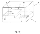
- FIG. 1a, 1b , 1c and 1d is shown schematically how a first part mold 4 is produced as a component of the embodiment of the metalworking tool 6 from a base body 2 made of at least one first plastic when the embodiment of the method according to the invention is carried out.
- the first partial mold 4 to be produced is designed and / or used as a hold-down device for the metalworking tool 6.
- the base body 2 is produced by performing a casting process with a casting mold.
- This first part shape 4 is, for example, designed and / or designated as a hold-down device.
- At least one area 10, 12, here two areas 10, 12 or surfaces is or are initially selected on an original surface 8 of the base body 2, onto which a layer 14, 16 of at least one second plastic is applied during the process to be applied or to be attached.
- a surface treatment measure is carried out for each of the two areas 10, 12 on the surface 8.
- a first, here planar or flat area 10, which is provided for a first layer 14, is located directly on and / or on the surface 8.
- plastic becomes removed and a recess 13 or depression and / or pocket formed on the originally flat or smooth surface 8, the second layer 16 being arranged on or on the second region 12 of the surface 8 in the recess 13.
- Each area 10, 12 is roughened here and an adhesive is applied to the roughened areas 10, 12 ( Figure 1b ).
- a casting mold 18 is arranged on the surface of the base body 2.
- the casting mold 18 comprises a recess 20 which is assigned to the first, here planar region 10 on the surface 8 of the base body 2. Furthermore, it is provided that the first region 10 on the surface 8 of the base body 2 and the recess 20 enclose a first cavity 24. In addition, a first channel 54 running within the casting mold 18 is assigned to the recess 20 and thus to the first cavity 24.
- a second planar, flat and / or smooth area of a surface of the casting mold 18 is assigned to the second area 12 and thus to the recess 13 on and / or on the surface 8 of the base body 2.
- the second area 12 with the recess 13 in the surface 8 of the base body 2 and the surface of the casting mold 18 enclose a second cavity 26.
- the second cavity 26 and / or the recess 13 on the surface 8 of the base body 2 is inside the casting mold 18 running channel 56 assigned.
- the at least one second plastic is filled in liquid form into the two cavities 24, 26 through the channels 54, 56. It is conceivable that in the first cavity 24 a first type or variety Plastic and a second type or type of plastic is filled into the second cavity 26, one or both types of plastic usually differing from the first plastic of the base body. Different plastics with different material properties, which have different chemical compositions and / or properties, can thus be used. The plastics harden within the respective cavities 24, 26.
- the first layer 14 is formed from the first type of plastic, which is attached to the roughened area 10 of the base body 8 that is provided with adhesive.
- the first layer 14 made of the first type of plastic includes a first thickness or height, a first coefficient of friction and a first spring stiffness.
- the second layer 16 made of the second type of plastic is attached to the second area 12 of the surface 8 and / or in the recess 13 arranged there, this second layer 16 here having a second thickness or height, a second coefficient of friction and a second spring stiffness which can differ in each case from the first thickness, the first coefficient of friction and the first spring stiffness of the first layer 14.
- a thickness of a respective layer 14, 16 is determined in a first step by a height and / or depth of a respective recess.
- the thickness is determined by the depth of the recess 20 of the casting mold 18, which is arranged on the flat area 10 of the surface 8, and by the depth of the recess 13 at the second area 12 of the surface 8, on which a flat area of the Casting mold 18 is arranged, determined, wherein a respective cavity 24, 26 is provided.
- Another possibility for controlling the thickness is to control an amount of the respective plastic to be filled in through the respective channel 54, 56, but which is shown in FIG in both cases for fine adjustment in a second step, if necessary by post-processing.
- Figure 1d also shows a second part 28 as a further component of the metalworking tool 6.
- This second part 28 has a surface 30 that is complementary to the surface 8 of the base body 2 with the layers 14, 16 of the first plastic attached to it.
- the second partial mold 28 has two recesses 42, 44 which are designed to be complementary to the layers 14, 16 made of the at least second plastic on the surface 8 of the first partial mold 4.
- a component made of metal usually made of sheet metal
- it is to be arranged between the two partial molds 4, 28 of the metalworking tool 6.
- the two partial molds 4, 28 are then moved towards one another, the component being pressed between the partial molds 4, 28.
- Figure 2 shows a further example of a first part shape 32 as a component of the second embodiment of the metalworking tool.
- This first partial mold 32 is also designed as a hold-down device and has a base body 34 made of plastic, on which a plurality of layers 36, 38, 44 made of different types of plastic with different thicknesses are fastened.
- the presented first partial molds 4, 32 of the metalworking tool are designed as hold-down devices to control a material flow of a component to be machined, with a distortion, a formation of Folding and / or upsetting of the component with the hold-down device is avoided.
Landscapes
- Engineering & Computer Science (AREA)
- Mechanical Engineering (AREA)
- Chemical & Material Sciences (AREA)
- Materials Engineering (AREA)
- Mounting, Exchange, And Manufacturing Of Dies (AREA)
- Moulds For Moulding Plastics Or The Like (AREA)
Claims (9)
- Procédé de fabrication d'une première partie de moule (4, 32) pour un outil d'usinage de métaux (6), dans lequel un corps de base (2, 34) en plastique est prévu pour la fabrication de la première partie de moule (4, 32), dans lequel une surface (8) du corps de base (2, 34) est divisée en plusieurs zones (10, 12), dans lequel au moins un moule de coulée (18) est disposé sur au moins une zone (10, 12) de la surface (8) du corps de base (2)
caractérisé en ce que
l'au moins un moule de coulée (18) et l'au moins une zone (10, 12) de la surface renferment au moins une cavité (24, 26) qui forme un moule négatif pour une couche (14, 16) de plastique à appliquer sur l'au moins une zone (10, 12), dans lequel du plastique est rempli et durci dans l'au moins une cavité (24, 26), dans lequel le plastique est lié à la surface (8) du corps de base (2, 34) au niveau de l'au moins une zone (10, 12) et est appliqué sur celle-ci en fournissant la couche (14, 16), dans lequel la première partie de moule (4, 32) est réalisée en tant que serre-flan. - Procédé selon la revendication 1, dans lequel au moins un type de plastique, qui présente au moins une propriété matérielle, est appliqué sur l'au moins une zone (10, 12).
- Procédé selon la revendication 1 ou 2, dans lequel des couches (14, 16) de plastique, qui diffèrent l'une de l'autre par au moins une propriété matérielle, sont appliquées sur au moins deux zones différentes (10, 12) de la surface (8) du corps de base.
- Procédé selon la revendication 2 ou 3, dans lequel un type de plastique, une dureté élastique ou un module d'élasticité du plastique, un coefficient de friction du plastique et/ou une épaisseur de la couche (14, 16) est pris en compte en tant qu'au moins une propriété matérielle de la couche respective (14, 16) de plastique.
- Procédé selon l'une quelconque des revendications précédentes, dans lequel l'au moins une zone (10, 12) est usinée avant que le moule de coulée (18) soit disposé.
- Procédé selon l'une quelconque des revendications précédentes, dans lequel le corps de base (2, 34) est coulé avec un moule de coulée.
- Procédé selon l'une quelconque des revendications précédentes, dans lequel une seconde partie de moule (28) en acier est prévue, qui est réalisée en contrepartie de la première partie de moule (4, 32).
- Procédé selon l'une quelconque des revendications précédentes, dans lequel le plastique est appliqué sur l'au moins une zone (10) de la surface (8) du corps de base (2, 34)
- Procédé selon l'une quelconque des revendications précédentes, dans lequel du plastique est d'abord enlevé de l'au moins une zone (12) de la surface (8) du corps de base (2) et un évidement (13) est formé, dans lequel l'au moins un moule de coulée (18) étant disposé sur l'au moins une zone (12) de la surface (8) du corps de base (2), dans lequel l'au moins un moule de coulée (18) et l'évidement (13) renferment au moins une cavité (26) au niveau de l'au moins une zone (12) de la surface, dans lequel du plastique est rempli et durci dans l'au moins une cavité (26), dans lequel le plastique est lié à la surface (8) du corps de base (2, 34) au niveau de l'au moins une zone (12) et est introduit dans l'évidement (13) en fournissant la couche (16).
Applications Claiming Priority (2)
| Application Number | Priority Date | Filing Date | Title |
|---|---|---|---|
| DE102016213375.6A DE102016213375B4 (de) | 2016-07-21 | 2016-07-21 | Verfahren zum Herstellen eines Metallbearbeitungswerkzeugs und Metallbearbeitungswerkzeug |
| PCT/EP2017/000754 WO2018014989A1 (fr) | 2016-07-21 | 2017-06-27 | Procédé de fabrication d'un outil d'usinage de métaux et outil d'usinage de métaux ainsi fabriqué |
Publications (2)
| Publication Number | Publication Date |
|---|---|
| EP3487645A1 EP3487645A1 (fr) | 2019-05-29 |
| EP3487645B1 true EP3487645B1 (fr) | 2021-08-18 |
Family
ID=59285138
Family Applications (1)
| Application Number | Title | Priority Date | Filing Date |
|---|---|---|---|
| EP17735391.9A Active EP3487645B1 (fr) | 2016-07-21 | 2017-06-27 | Procédé de fabrication d'un outil d'usinage de métaux |
Country Status (5)
| Country | Link |
|---|---|
| US (1) | US11478959B2 (fr) |
| EP (1) | EP3487645B1 (fr) |
| CN (1) | CN109475919B (fr) |
| DE (1) | DE102016213375B4 (fr) |
| WO (1) | WO2018014989A1 (fr) |
Families Citing this family (3)
| Publication number | Priority date | Publication date | Assignee | Title |
|---|---|---|---|---|
| DE102018212457A1 (de) | 2018-07-26 | 2020-01-30 | Audi Ag | Verfahren zum Herstellen einer Teilform für ein Metallbearbeitungswerkzeug |
| CN112719819B (zh) * | 2019-10-14 | 2021-12-28 | 常州星宇车灯股份有限公司 | 一种异形车灯模具零件的基准转换方法 |
| CN113183369B (zh) * | 2021-05-31 | 2025-07-29 | 河源金三维智造有限公司 | 一种汽车衬垫模具的型芯结构及其加工方法 |
Family Cites Families (7)
| Publication number | Priority date | Publication date | Assignee | Title |
|---|---|---|---|---|
| FR2655892A1 (fr) | 1989-12-18 | 1991-06-21 | Lorraine Laminage | Procede et dispositif de mise en forme d'un flan de tole notamment pour realiser un masque de tube cathodique et masque de tube cathodique obtenu selon ce procede. |
| CN1182667A (zh) | 1996-11-15 | 1998-05-27 | 宜兴市东方泵阀设备厂 | 整体衬塑离心泵蜗壳及成型模具和成型方法 |
| DE10155233A1 (de) | 2001-11-09 | 2003-05-22 | Volkswagen Ag | Werkzeug aus Kunststoff |
| DE10155234A1 (de) | 2001-11-09 | 2003-05-22 | Volkswagen Ag | Werkzeug aus Kunststoff |
| DE10231001A1 (de) | 2002-07-09 | 2004-02-12 | Volkswagen Ag | Aus Kunststoff bestehendes Werkzeug |
| DE102009031453A1 (de) | 2009-07-02 | 2011-01-05 | Werner Beuerlein | Gussform mit Entlüfter |
| DE102010011087A1 (de) | 2010-03-12 | 2011-09-15 | Volkswagen Ag | Verfahren zum Herstellen eines kühlbaren Formwerkzeugs |
-
2016
- 2016-07-21 DE DE102016213375.6A patent/DE102016213375B4/de active Active
-
2017
- 2017-06-27 EP EP17735391.9A patent/EP3487645B1/fr active Active
- 2017-06-27 WO PCT/EP2017/000754 patent/WO2018014989A1/fr not_active Ceased
- 2017-06-27 US US16/318,159 patent/US11478959B2/en active Active
- 2017-06-27 CN CN201780044656.5A patent/CN109475919B/zh active Active
Non-Patent Citations (1)
| Title |
|---|
| None * |
Also Published As
| Publication number | Publication date |
|---|---|
| WO2018014989A1 (fr) | 2018-01-25 |
| DE102016213375A1 (de) | 2018-01-25 |
| CN109475919A (zh) | 2019-03-15 |
| US20190283104A1 (en) | 2019-09-19 |
| US11478959B2 (en) | 2022-10-25 |
| DE102016213375B4 (de) | 2022-10-13 |
| CN109475919B (zh) | 2021-06-25 |
| EP3487645A1 (fr) | 2019-05-29 |
Similar Documents
| Publication | Publication Date | Title |
|---|---|---|
| DE112009001712B4 (de) | Werkstückbiegeverfahren | |
| EP3197633B1 (fr) | Procédé et dispositif de production combinée d'éléments au moyen d'un formage incrémental de tôles et de procédés additifs en une seule passe | |
| EP2701861B1 (fr) | Procédé et dispositif de fabrication de pièces embouties sans bride | |
| DE102013114245B3 (de) | Verfahren und Vorrichtung zur Herstellung warmumgeformter Radschüsseln | |
| EP2259883B1 (fr) | Procédé de commande de flux de matière lors de l'emboutissage profond d'une pièce et dispositif d'emboutissage profond | |
| DE102011115219A1 (de) | Verfahren und Vorrichtung zur Herstellung eines Blechformteils unter Vermeidung von Nachlaufkanten | |
| EP3519121B1 (fr) | Procédé de fabrication d'éléments comportant une zone de fond adaptée | |
| EP3487645B1 (fr) | Procédé de fabrication d'un outil d'usinage de métaux | |
| DE10324244A1 (de) | Verfahren zur Herstellung individualisierter Außenhautblechteile aus in Serienfertigung hergestellten Serienaußenhautblechteilen für Fahrzeuge sowie nach diesem Verfahren hergestellte Außenhautblechteile | |
| EP2208551B1 (fr) | Procédé de fabrication d'une pièce de tôle préformée complexe | |
| DE102011054866A1 (de) | Verfahren zur Herstellung eines warmumgeformten und pressgehärteten Kraftfahrzeugkarosseriebauteils sowie Kraftfahrzeugkarosseriebauteil | |
| EP3778062B1 (fr) | Procédé de changement de forme d'une pièce de type plaque | |
| DE69006147T2 (de) | Verfahren zum Bearbeiten von Matrizen. | |
| EP3254780B1 (fr) | Procédé de fabrication d'un outil de formage d'une pièces métallique | |
| EP3439807A1 (fr) | Procédé et dispositif de formage d'un demi-produit | |
| DE102012020646A1 (de) | Verfahren zur Herstellung eines Bauteils für ein Kraftfahrzeug | |
| DE602004001441T2 (de) | Vorrichtung und Verfahren zum Umformen von Metallblechen an kritischen Flächen von Verkleidungsteilen | |
| DE102018108391A1 (de) | Verfahren zum Konstruieren eines Umformelements für ein Umformwerkzeug und ein mittels eines solchen Verfahrens hergestelltes Umformelement | |
| DE102020209770A1 (de) | Additiv hergestellter Werkzeugeinsatz eines Tiefziehwerkzeugs | |
| EP1741497B9 (fr) | Procédé et dispositif pour produire sans enlèvement de matière une encoche dans une pièce et pièce avec une telle encoche | |
| DE102013204011A1 (de) | Verfahren zur Auslegung eines Umformwerkzeugs | |
| EP4541479A1 (fr) | Machine à poinçonner | |
| DE202023107319U1 (de) | Prägewerkzeug | |
| EP3147041B1 (fr) | Procédé et appareil de cintrage d'un produit semi-fini métallique | |
| DE102010037958B4 (de) | Verfahren zur Herstellung eines Umformwerkzeuges für Dichtungen oder Einzellagen von Dichtungen, Umformwerkzeug, Dichtung und Presse |
Legal Events
| Date | Code | Title | Description |
|---|---|---|---|
| STAA | Information on the status of an ep patent application or granted ep patent |
Free format text: STATUS: UNKNOWN |
|
| STAA | Information on the status of an ep patent application or granted ep patent |
Free format text: STATUS: THE INTERNATIONAL PUBLICATION HAS BEEN MADE |
|
| PUAI | Public reference made under article 153(3) epc to a published international application that has entered the european phase |
Free format text: ORIGINAL CODE: 0009012 |
|
| STAA | Information on the status of an ep patent application or granted ep patent |
Free format text: STATUS: REQUEST FOR EXAMINATION WAS MADE |
|
| 17P | Request for examination filed |
Effective date: 20190221 |
|
| AK | Designated contracting states |
Kind code of ref document: A1 Designated state(s): AL AT BE BG CH CY CZ DE DK EE ES FI FR GB GR HR HU IE IS IT LI LT LU LV MC MK MT NL NO PL PT RO RS SE SI SK SM TR |
|
| AX | Request for extension of the european patent |
Extension state: BA ME |
|
| DAV | Request for validation of the european patent (deleted) | ||
| DAX | Request for extension of the european patent (deleted) | ||
| STAA | Information on the status of an ep patent application or granted ep patent |
Free format text: STATUS: EXAMINATION IS IN PROGRESS |
|
| 17Q | First examination report despatched |
Effective date: 20201014 |
|
| GRAP | Despatch of communication of intention to grant a patent |
Free format text: ORIGINAL CODE: EPIDOSNIGR1 |
|
| STAA | Information on the status of an ep patent application or granted ep patent |
Free format text: STATUS: GRANT OF PATENT IS INTENDED |
|
| INTG | Intention to grant announced |
Effective date: 20210527 |
|
| GRAS | Grant fee paid |
Free format text: ORIGINAL CODE: EPIDOSNIGR3 |
|
| GRAA | (expected) grant |
Free format text: ORIGINAL CODE: 0009210 |
|
| STAA | Information on the status of an ep patent application or granted ep patent |
Free format text: STATUS: THE PATENT HAS BEEN GRANTED |
|
| AK | Designated contracting states |
Kind code of ref document: B1 Designated state(s): AL AT BE BG CH CY CZ DE DK EE ES FI FR GB GR HR HU IE IS IT LI LT LU LV MC MK MT NL NO PL PT RO RS SE SI SK SM TR |
|
| REG | Reference to a national code |
Ref country code: GB Ref legal event code: FG4D Free format text: NOT ENGLISH |
|
| REG | Reference to a national code |
Ref country code: CH Ref legal event code: EP |
|
| REG | Reference to a national code |
Ref country code: DE Ref legal event code: R096 Ref document number: 502017011229 Country of ref document: DE |
|
| REG | Reference to a national code |
Ref country code: IE Ref legal event code: FG4D Free format text: LANGUAGE OF EP DOCUMENT: GERMAN Ref country code: AT Ref legal event code: REF Ref document number: 1421154 Country of ref document: AT Kind code of ref document: T Effective date: 20210915 |
|
| REG | Reference to a national code |
Ref country code: LT Ref legal event code: MG9D |
|
| REG | Reference to a national code |
Ref country code: NL Ref legal event code: MP Effective date: 20210818 |
|
| PG25 | Lapsed in a contracting state [announced via postgrant information from national office to epo] |
Ref country code: HR Free format text: LAPSE BECAUSE OF FAILURE TO SUBMIT A TRANSLATION OF THE DESCRIPTION OR TO PAY THE FEE WITHIN THE PRESCRIBED TIME-LIMIT Effective date: 20210818 Ref country code: RS Free format text: LAPSE BECAUSE OF FAILURE TO SUBMIT A TRANSLATION OF THE DESCRIPTION OR TO PAY THE FEE WITHIN THE PRESCRIBED TIME-LIMIT Effective date: 20210818 Ref country code: SE Free format text: LAPSE BECAUSE OF FAILURE TO SUBMIT A TRANSLATION OF THE DESCRIPTION OR TO PAY THE FEE WITHIN THE PRESCRIBED TIME-LIMIT Effective date: 20210818 Ref country code: BG Free format text: LAPSE BECAUSE OF FAILURE TO SUBMIT A TRANSLATION OF THE DESCRIPTION OR TO PAY THE FEE WITHIN THE PRESCRIBED TIME-LIMIT Effective date: 20211118 Ref country code: LT Free format text: LAPSE BECAUSE OF FAILURE TO SUBMIT A TRANSLATION OF THE DESCRIPTION OR TO PAY THE FEE WITHIN THE PRESCRIBED TIME-LIMIT Effective date: 20210818 Ref country code: PT Free format text: LAPSE BECAUSE OF FAILURE TO SUBMIT A TRANSLATION OF THE DESCRIPTION OR TO PAY THE FEE WITHIN THE PRESCRIBED TIME-LIMIT Effective date: 20211220 Ref country code: NO Free format text: LAPSE BECAUSE OF FAILURE TO SUBMIT A TRANSLATION OF THE DESCRIPTION OR TO PAY THE FEE WITHIN THE PRESCRIBED TIME-LIMIT Effective date: 20211118 Ref country code: FI Free format text: LAPSE BECAUSE OF FAILURE TO SUBMIT A TRANSLATION OF THE DESCRIPTION OR TO PAY THE FEE WITHIN THE PRESCRIBED TIME-LIMIT Effective date: 20210818 Ref country code: ES Free format text: LAPSE BECAUSE OF FAILURE TO SUBMIT A TRANSLATION OF THE DESCRIPTION OR TO PAY THE FEE WITHIN THE PRESCRIBED TIME-LIMIT Effective date: 20210818 |
|
| PG25 | Lapsed in a contracting state [announced via postgrant information from national office to epo] |
Ref country code: PL Free format text: LAPSE BECAUSE OF FAILURE TO SUBMIT A TRANSLATION OF THE DESCRIPTION OR TO PAY THE FEE WITHIN THE PRESCRIBED TIME-LIMIT Effective date: 20210818 Ref country code: LV Free format text: LAPSE BECAUSE OF FAILURE TO SUBMIT A TRANSLATION OF THE DESCRIPTION OR TO PAY THE FEE WITHIN THE PRESCRIBED TIME-LIMIT Effective date: 20210818 Ref country code: GR Free format text: LAPSE BECAUSE OF FAILURE TO SUBMIT A TRANSLATION OF THE DESCRIPTION OR TO PAY THE FEE WITHIN THE PRESCRIBED TIME-LIMIT Effective date: 20211119 |
|
| PG25 | Lapsed in a contracting state [announced via postgrant information from national office to epo] |
Ref country code: NL Free format text: LAPSE BECAUSE OF FAILURE TO SUBMIT A TRANSLATION OF THE DESCRIPTION OR TO PAY THE FEE WITHIN THE PRESCRIBED TIME-LIMIT Effective date: 20210818 |
|
| PG25 | Lapsed in a contracting state [announced via postgrant information from national office to epo] |
Ref country code: DK Free format text: LAPSE BECAUSE OF FAILURE TO SUBMIT A TRANSLATION OF THE DESCRIPTION OR TO PAY THE FEE WITHIN THE PRESCRIBED TIME-LIMIT Effective date: 20210818 |
|
| REG | Reference to a national code |
Ref country code: DE Ref legal event code: R097 Ref document number: 502017011229 Country of ref document: DE |
|
| PG25 | Lapsed in a contracting state [announced via postgrant information from national office to epo] |
Ref country code: SM Free format text: LAPSE BECAUSE OF FAILURE TO SUBMIT A TRANSLATION OF THE DESCRIPTION OR TO PAY THE FEE WITHIN THE PRESCRIBED TIME-LIMIT Effective date: 20210818 Ref country code: SK Free format text: LAPSE BECAUSE OF FAILURE TO SUBMIT A TRANSLATION OF THE DESCRIPTION OR TO PAY THE FEE WITHIN THE PRESCRIBED TIME-LIMIT Effective date: 20210818 Ref country code: RO Free format text: LAPSE BECAUSE OF FAILURE TO SUBMIT A TRANSLATION OF THE DESCRIPTION OR TO PAY THE FEE WITHIN THE PRESCRIBED TIME-LIMIT Effective date: 20210818 Ref country code: EE Free format text: LAPSE BECAUSE OF FAILURE TO SUBMIT A TRANSLATION OF THE DESCRIPTION OR TO PAY THE FEE WITHIN THE PRESCRIBED TIME-LIMIT Effective date: 20210818 Ref country code: CZ Free format text: LAPSE BECAUSE OF FAILURE TO SUBMIT A TRANSLATION OF THE DESCRIPTION OR TO PAY THE FEE WITHIN THE PRESCRIBED TIME-LIMIT Effective date: 20210818 Ref country code: AL Free format text: LAPSE BECAUSE OF FAILURE TO SUBMIT A TRANSLATION OF THE DESCRIPTION OR TO PAY THE FEE WITHIN THE PRESCRIBED TIME-LIMIT Effective date: 20210818 |
|
| PLBE | No opposition filed within time limit |
Free format text: ORIGINAL CODE: 0009261 |
|
| STAA | Information on the status of an ep patent application or granted ep patent |
Free format text: STATUS: NO OPPOSITION FILED WITHIN TIME LIMIT |
|
| 26N | No opposition filed |
Effective date: 20220519 |
|
| PG25 | Lapsed in a contracting state [announced via postgrant information from national office to epo] |
Ref country code: IT Free format text: LAPSE BECAUSE OF FAILURE TO SUBMIT A TRANSLATION OF THE DESCRIPTION OR TO PAY THE FEE WITHIN THE PRESCRIBED TIME-LIMIT Effective date: 20210818 |
|
| PG25 | Lapsed in a contracting state [announced via postgrant information from national office to epo] |
Ref country code: SI Free format text: LAPSE BECAUSE OF FAILURE TO SUBMIT A TRANSLATION OF THE DESCRIPTION OR TO PAY THE FEE WITHIN THE PRESCRIBED TIME-LIMIT Effective date: 20210818 |
|
| PG25 | Lapsed in a contracting state [announced via postgrant information from national office to epo] |
Ref country code: MC Free format text: LAPSE BECAUSE OF FAILURE TO SUBMIT A TRANSLATION OF THE DESCRIPTION OR TO PAY THE FEE WITHIN THE PRESCRIBED TIME-LIMIT Effective date: 20210818 |
|
| REG | Reference to a national code |
Ref country code: CH Ref legal event code: PL |
|
| REG | Reference to a national code |
Ref country code: BE Ref legal event code: MM Effective date: 20220630 |
|
| PG25 | Lapsed in a contracting state [announced via postgrant information from national office to epo] |
Ref country code: LU Free format text: LAPSE BECAUSE OF NON-PAYMENT OF DUE FEES Effective date: 20220627 Ref country code: LI Free format text: LAPSE BECAUSE OF NON-PAYMENT OF DUE FEES Effective date: 20220630 Ref country code: IE Free format text: LAPSE BECAUSE OF NON-PAYMENT OF DUE FEES Effective date: 20220627 Ref country code: CH Free format text: LAPSE BECAUSE OF NON-PAYMENT OF DUE FEES Effective date: 20220630 |
|
| PG25 | Lapsed in a contracting state [announced via postgrant information from national office to epo] |
Ref country code: BE Free format text: LAPSE BECAUSE OF NON-PAYMENT OF DUE FEES Effective date: 20220630 |
|
| P01 | Opt-out of the competence of the unified patent court (upc) registered |
Effective date: 20230530 |
|
| REG | Reference to a national code |
Ref country code: AT Ref legal event code: MM01 Ref document number: 1421154 Country of ref document: AT Kind code of ref document: T Effective date: 20220627 |
|
| PG25 | Lapsed in a contracting state [announced via postgrant information from national office to epo] |
Ref country code: AT Free format text: LAPSE BECAUSE OF NON-PAYMENT OF DUE FEES Effective date: 20220627 |
|
| PG25 | Lapsed in a contracting state [announced via postgrant information from national office to epo] |
Ref country code: HU Free format text: LAPSE BECAUSE OF FAILURE TO SUBMIT A TRANSLATION OF THE DESCRIPTION OR TO PAY THE FEE WITHIN THE PRESCRIBED TIME-LIMIT; INVALID AB INITIO Effective date: 20170627 |
|
| PG25 | Lapsed in a contracting state [announced via postgrant information from national office to epo] |
Ref country code: MK Free format text: LAPSE BECAUSE OF FAILURE TO SUBMIT A TRANSLATION OF THE DESCRIPTION OR TO PAY THE FEE WITHIN THE PRESCRIBED TIME-LIMIT Effective date: 20210818 Ref country code: CY Free format text: LAPSE BECAUSE OF FAILURE TO SUBMIT A TRANSLATION OF THE DESCRIPTION OR TO PAY THE FEE WITHIN THE PRESCRIBED TIME-LIMIT Effective date: 20210818 |
|
| PG25 | Lapsed in a contracting state [announced via postgrant information from national office to epo] |
Ref country code: TR Free format text: LAPSE BECAUSE OF FAILURE TO SUBMIT A TRANSLATION OF THE DESCRIPTION OR TO PAY THE FEE WITHIN THE PRESCRIBED TIME-LIMIT Effective date: 20210818 |
|
| PG25 | Lapsed in a contracting state [announced via postgrant information from national office to epo] |
Ref country code: MT Free format text: LAPSE BECAUSE OF FAILURE TO SUBMIT A TRANSLATION OF THE DESCRIPTION OR TO PAY THE FEE WITHIN THE PRESCRIBED TIME-LIMIT Effective date: 20210818 |
|
| PGFP | Annual fee paid to national office [announced via postgrant information from national office to epo] |
Ref country code: DE Payment date: 20250630 Year of fee payment: 9 |
|
| PGFP | Annual fee paid to national office [announced via postgrant information from national office to epo] |
Ref country code: GB Payment date: 20250621 Year of fee payment: 9 |
|
| PGFP | Annual fee paid to national office [announced via postgrant information from national office to epo] |
Ref country code: FR Payment date: 20250617 Year of fee payment: 9 |