EP3490384B1 - Appareil de retrait d'arête intramusculaire - Google Patents
Appareil de retrait d'arête intramusculaire Download PDFInfo
- Publication number
- EP3490384B1 EP3490384B1 EP17833617.8A EP17833617A EP3490384B1 EP 3490384 B1 EP3490384 B1 EP 3490384B1 EP 17833617 A EP17833617 A EP 17833617A EP 3490384 B1 EP3490384 B1 EP 3490384B1
- Authority
- EP
- European Patent Office
- Prior art keywords
- unit
- bone removal
- pin
- removal apparatus
- pin bone
- Prior art date
- Legal status (The legal status is an assumption and is not a legal conclusion. Google has not performed a legal analysis and makes no representation as to the accuracy of the status listed.)
- Active
Links
Images


Classifications
-
- A—HUMAN NECESSITIES
- A22—BUTCHERING; MEAT TREATMENT; PROCESSING POULTRY OR FISH
- A22C—PROCESSING MEAT, POULTRY, OR FISH
- A22C25/00—Processing fish ; Curing of fish; Stunning of fish by electric current; Investigating fish by optical means
- A22C25/16—Removing fish-bones; Filleting fish
- A22C25/166—Removing loose pin bones, e.g. from fish fillets
Definitions
- the present invention relates to a pin bone removal apparatus, for removing pin bones in fish flesh, where the pin bone removal apparatus comprises at least a conveyor and a pin bone removal unit.
- WO2016/08926 A discloses a pin bone removal system adapted to automatically removing a pin bone area of a fish fillet when conveyed by a conveyor after undergoing a cutting process. Initially, the pin bone area has been cut from the remaining part of the fish fillet in a preceding step, but is not yet separated from the remainder of the fillet. The transversal position of the fish fillet in relation to the first end is adjusted such that when the fish fillet arrives at the downstream position the position of the cut pin bone area is such that the cut pin bone area falls through the space while the remaining part of the fish fillet remains on the first and/or second conveyor belts.
- EP 2531038 B discloses a food processing apparatus adapted for detecting and cutting tough tissues, e.g. bones, from food items in order to remove tough tissues from food item pieces and thus increase the cutting yield.
- the food items may e.g. be fish fillets.
- a tough tissue detection means e.g. an X-ray machine, is used for imaging incoming food items and based on the imaging generating first image data indicating the location of the tough tissues in said food items.
- a control unit operates a cutting means based on the first image data so as to cut portions of said incoming food items containing the tough items/bones.
- a second image data e.g. 2D or 3D images, may be used for calculating weight, volume, thickness and/or colour of the food item.
- WO 2013/132068 A discloses a cutting apparatus for cutting food items, in particular for cutting pin bone areas from fish fillets.
- the food item conveyed on a conveyor and a cutter is arranged above a gap extending across the at least one conveyor belt.
- the cutter is positioned in relation to the gap such that the cutting path of the cutter extends through the food items and the gap.
- the cutter is adapted to be connected to a control mechanism for operating crosswise movement of the cutter along the gap and thus controls the back and forth movement of the cutter parallel to the conveying direction.
- the cutter may contain an X-ray unit that detects the items, e.g. bones that are to be cut from the food item.
- EP 2337456 B discloses a method for extracting pin bones from a fillet wherein the pin bones are extracted by means of a tool having a certain speed relative to the fillet.
- the tool is displaced at a first relative speed along a first fillet portion where the fillet has pin bones and at a second (faster) relative speed along a second fillet portion where the fillet has no pin bones.
- EP 1284604 A1 discloses a method for removing pin bones from the fish meat parts before resolution of rigor.
- the method comprises detecting the position of the pin bones in the fish, e.g.by image analysis, fluorescence techniques, near infrared spectroscopy, (NIR) or Infrared spectroscopy (IR).
- NIR near infrared spectroscopy
- IR Infrared spectroscopy
- the pin bones can be separated from the fish part by conventional methods, e.g. dragging or pulling the row of pin bones from the fish meat and thereby only removing a minimum of fish meat with the pin bones.
- EP 2531038 A1 discloses a system adapted to cut pin bones fully automatically from pre-rigor salmon fillets or white fish fillets.
- the system comprises conveyers, detection means, i.e. an X-ray machine, which captures an image of the fillet as well as the precise location of the bones in the fillet, a vision unit used to capture one or more of the following; silhouette image, full colour image and full 3D scan image and a cutting unit, e.g. on a robotic arm.
- US 7247086 B2 discloses an apparatus and a procedure for pin boning fish.
- the apparatus comprises a conveyor, a housing comprising a pin boning device, which can be based in roller and edging, discs or forceps, moved by an arm, where the arm can be controlled by a robotic system.
- Fig. 7c shows four flexible pull mechanism arranged next to each other.
- WO 99/52375 A discloses method and apparatus for removing bones from meat, such as pin-bones from fish fillets especially from whitefish, such as cod.
- the apparatus comprises a conveyor for transporting the meat and a bone removing unit for removing the bones as the meat is transported along the conveyor.
- the bone removing unit is movably hinged to the frame of the apparatus and moveable in an approximated up- and downward direction toward the conveyor.
- the conveyor comprises an upwardly extending edge allowing the bone removal unit to be brought into contact with a particular area to remove the bones. In this manner it is possible to adjust the apparatus according to each individual fish fillet.
- WO 01/43553 A1 discloses methods and apparatus for removing bones from meat, such as pin bones from fish filets.
- the apparatus comprises a conveyor for advancing the filets along and a bone removing unit for picking unwanted bones from a particular area of the meat as it is transported along the conveyor.
- the bone removing unit is hinged to a frame via two individually movable arms, and comprises two main parts, a rotatable driven axel and a counter pressure element and optional a first pressure element.
- GB 1513243 A discloses a method for filleting fish and removing pin bones while these are attached to the skeleton and prior to filleting of the fish.
- the system is using heat, such as steam, in a local treatment to the fish skin along a zone, usually a narrow strip where the pin bones are connected to the fish skin, thereby weakening or destroying the skin connection.
- US 6280313 B1 discloses a catfish fillet machine comprising one or more nozzles that can be used to provide a water spray to cleanse the cutter from any remaining fin and bone debris such that the cutter is self-cleaning between each filleting of fish.
- DE102015111448 discloses device comprising clamping jaws, where the clamping jaws are designed and arranged so that they can be moved toward and away from each other, and a drive is designed and arranged to exert an oscillating rotational movement of the base body about an axis of rotation and thereby of the clamping jaws about the center axis M.
- JP 2014 014346 A discloses a method of pin bone removal where the fillets come to a complete stop during each operation step. Additionally, fillets are fixed and located in trays which does not make it possible to operate the system in motion.
- the object of this invention is to provide a pin bone removal apparatus of the type mentioned in the introduction which changes the prior art methods by adding both intelligence and individuality to the process.
- an intelligent pin bone removal apparatus to comprise apparatus for temperature manipulation in front of the pin bone removal apparatus or built together with the pin bone removal apparatus, where the temperature manipulation apparatus works:
- the present invention relates to a pin bone removal apparatus for removing pin bones in fish flesh according to independent claim 1.
- the pin bone removal apparatus comprises at least a conveyor and a pin bone removal unit, where the pin bone removal apparatus further comprises at least one scanner in front of the pin bone removal unit, and where the scanner comprises at least a positioning unit and a bone detection unit.
- a simple position and/or surface scanner can also control position of pin bone rollers. So any kind of scanner or sensor (electrical or mechanical) used to position and thereafter control roller position to individual fillet + MR scanner type.
- the fillets are then detected in terms of their location on the conveyor and the bones detected.
- the pin bone removal apparatus could be two individual machines, but functions could be within one machine frame as well.
- the pin bone removal unit comprises at least two flexible pull mechanisms arranged on at least one arm, where the at least one arm has a number of flexibly positioning means, which can react on the individual fillets in motion.
- the pin bones are exposed from the vertebra after filleting but piece of cartilage fastens this to the skin.
- a number of positioning means is meant at least one of a linear movement of the arm, a rotating movement around the axes of the arm or around a swivel at the end of the arm where the axis of the swivel is at least parallel to the axis of the arm. It could likewise be a rotating movement around a swivel at the end of the arm where the axis of the swivel is different from parallel to the axis of the arm, preferably perpendicular to the axis of the arm.
- telescopic coaxial axes are used as well as swivels, however other construction means could just as well be used to conduct the same kind of movements.
- the at least two flexible pull mechanisms are arranged next to and/or in succession of each other, which can react to individual fillets in motion.
- each pull mechanism comprises at least one rotating head.
- the rotating head is a rotating drum, which is intended to roll over the fillets where the pin bones are placed.
- the pin bones are exposed from the vertebra after filleting but piece of cartilage fastens this to the skin.
- the rotating drums have a number of flexible positioning means.
- a number of positioning means is meant at least one of being adjustable in vertical angle, being adjustable in 360 degrees or being able to run in both directions (clockwise and anticlockwise looking from the centre of rotation) and with variable speed.
- the pin bone removal apparatus has at least four rotating drums/rollers where the rollers are arranged two and two in parallel and two and two after each other.
- the positioning unit is a 3D surface scan unit and the bone detection unit is an x-ray unit.
- the positioning unit is a 3D surface scan unit and the bone detection unit is a MR- scanning unit.
- the pin bone removal unit further comprises at least one temperature manipulation unit configured to conduct a controlled heating of at least one selective area of the fish flesh and where the controlled temperature manipulation unit comprises either a microwave unit, an infrared unit or a laser unit.
- the fillets are then detected in terms of their location on the conveyor and the bones detected, where after tendering process is activated. This is done by manipulating the temperature through targeted heating of bone roots, where especially the bones are fastened.
- the flesh will heat up the fastest, where the fat layer is thick, and bones are fastened to the skin.
- the temperature control ensures that it will only allow the area to tender and not the fillet to cook.
- the temperature manipulation unit is preferably followed by the pin bone removal unit which could further be followed by a skinning machine or alternatively could a skinning machine follow after the temperature manipulation unit and before the pin bone removal unit. Both options are possible due to the fact that the skinning process becomes easier after the temperature manipulation unit.
- microwave unit also is able to operate without the scanner.
- the process can be summarized as a two-step procedure, but not limited to:
- the flesh will heat up the fastest, where the fat layer is thick, and bones are fastened to the skin.
- the temperature control ensures that it will only allow the area to tender and not the fillet to cook, hence a controlled heating of at least one selective area of the fish.
- the pin bone removal apparatus comprising a temperature manipulation unit as explained would be a pre-rigor and fresh fish pin bone removal apparatus.
- a pre-rigor and fresh fish pin bone removal apparatus is meant a single unit machine or a combination of units working together one after another in a line, thus in-line.
- the conveyor is preferably a single conveyor that transports the fish through the entire pre-rigor and fresh fish pin bone apparatus such that the fish do not change its position between the units of the pre-rigor and fresh fish pin bone apparatus.
- it could be a number of conveyors as long as the fish do not change its position.
- the conveyor is able to move the fillets forward in a flow, where it is understood that a flow is both considered to be controllable steps or forward continuous movement, where the fillets are in motion at both steps/movement.
- the temperature manipulation unit is able to work from any side of the fish, whether that may be from above, below, front, back or from the sides. Furthermore, is it able to work from at least one angle, where it by angle is meant angle in relation to the surface of the fish.
- pre-rigor and fresh fish pin bone removal apparatus For the pre-rigor and fresh fish pin bone removal apparatus to be able to work at all it is preferably driven by electricity.
- the pin bone removal apparatus comprises a laser unit, where at least the laser unit further comprises a laser tool arranged at a robotic arm.
- the robotic arm part of a flex picker robot In a preferred embodiment is the robotic arm part of a flex picker robot. In an alternative embodiment another type of robot could be used. It is also possible to have the laser perform a certain system of movements, whether that is in a tilted angle, zigzag, from side to side or other patterns or movements.
- servo motors as rotary or linear actuators are used due to their ability to conduct precise control of positions, angularly or linearly. Servo motors also have the ability to control velocity as well as acceleration.
- the pin bone removal apparatus comprises a cabinet with self-cleaning means.
- the automated inside cleaning cabinets comprise moveable and/or fixed spray bars.
- the automated inside cleaning cabinets further comprise a sloped bottom section.
- the bottom is sloped to one end of the cabinet, in another embodiment to the other end or in a third embodiment at the bottom centre of the cabinet.
- the invention could be a single unit machine or a combination from two or more individual machines working together.
- the machine frames and cabinets are made to connect with each other and allow for completely automatized inside cleaning.
- Movable and fixed spray bars combined with a sloped bottom section is making it possible to make a complete internal wash down.
- the invention also includes or at least could include a system for control- and regulating the apparatus comprising different technical items, such as for example microprocessors, sensors, timers, motors and actuators, which are not all described in the specification, but as one of ordinary skill will recognize necessary to the invention, to make it function properly.
- a system for control- and regulating the apparatus comprising different technical items, such as for example microprocessors, sensors, timers, motors and actuators, which are not all described in the specification, but as one of ordinary skill will recognize necessary to the invention, to make it function properly.
- the present invention further relates to the use of a pin bone removal apparatus as disclosed above for removing pin bones in fillets of salmon, according to independent claim 11.
- Figure 1 shows a manually method of prior art, where operators have small tools 1 to pick the bones 2 from the fish flesh 3.
- Figure 2 shows a semi-automatic method of prior art, where a handheld rotating shredded drum 4 is positioned to rip the pin bones 2 from the fish flesh 3.
- Figure 3 shows an automatic method of prior art, where a conveyor 5 takes the fish fillet 6 through one or more automatic rotating drums 7.
- Figure 4 shows 6 lanes 39 inclusive divider 40 and merger 41.
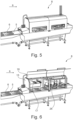
- Figure 5 shows an intelligent pin bone removal apparatus 8 in closed position, where a conveyor 5 is transporting fish fillets 6 in the direction of processing 9.
- Figure 6 shows an intelligent pin bone removal apparatus 8 in open position.
- the figure shows the position unit 17 as well as the pull mechanism 26.
- open position is meant that the cabinet 15 has a hatch 16, a door or a similar device which can be opened and closed.
- Figure 7 shows a scanner 10.
- Figure 8a shows a 3D surface scanning of a fish fillet conducted by a positioning unit 17 in terms of a 3D surface scan unit 17a;
- figure 8b shows a bone scanning conducted by a bone detection unit 18 either in terms of an x-ray unit 18a or a MR scanning unit 18b.
- Figure 8c shows a fish fillet 6 with pin bones 2.
- Figure 9 shows a microwave unit 13, in open position.
- Figure 10 shows microwaves 19 (just one wave is shown as a sinus heat curve for illustration) from the microwave unit 13 that hit the fish fillet 6 whereby the tendering process is then activated. This is done by manipulating the temperature, where especially the bones are fastened. Fat is more aqueous than flesh or meat, which means that the fat becomes warmer before the meat when exposed for microwaves. Since the bones are fastened to the fat which again is fastened to the skin the coherence becomes weaker and the bones becomes thus easier to pull without damaging the flesh of the fish.
- Figure 11 shows the "Thermal mode" with depth impact.
- Figure 12 shows a laser unit 14, in open position where a laser tool 20 is mounted on a flex picker robot 21.
- Figure 13 shows a laser beam 22 from the laser unit 14, where the laser beam 22 hit the fish fillet 6 whereby the tendering process is then activated by manipulating the temperature, where especially the bones are fastened. With laser technology this can be done very precisely.
- Figure 14 shows the "Thermal mode”.
- Figure 15 shows a pin bone removal unit 12 where four pull mechanism are arranged next to and in succession of each other, such that two and two are arranged next to each other and two and two in succession of each other.
- Figure 16a shows a salmon 23 in cross section with its bone structure comprising backbone 24 and pin bones 2.
- Figure 16b shows a fillet 6 with pin bones 2 in the lengthwise direction of the fish fillet 6
- figure 16c shows a fillet 6 with pin bones 2 in a cross section of the fish fillet 6.
- the pin bones 2 are exposed from the backbone 24 after filleting but piece of cartilage fastens the pin bones 2 to the skin 25.
- Figure 17a-f shows the flexibly positioning means of the pull mechanism 26 arranged on at least one arm 27 of the pin bone removal unit 12, which allows the pull mechanism 26 shown as a rotating drum 28 flexibly positioning means to optimize the picking angle.
- Figure 17a shows an example of a linear movement 29 of the arm 27 adjustable up and down in height (vertical)
- figure 17b an example of a front to end displacement as linear movement 42 in length (horizontal)
- figure 17c an example of a first rotating movement 30 adjustable in an angle around a first swivel 31 at the end of the arm
- figure 17d an example of a side to side displacement as linear movement 43 in width (horizontal)
- figure 17e shows a second rotating movement 32 adjustable 360 degrees around a second swivel 33 at the end of the arm 27 where the axis of the second swivel 33 is parallel to the axis of the arm 27, figure 17f shows that rotating drums 28 are able to run in both directions, rotating movement 44 and with variable speed.
- Figure 18a-c shows examples of fillets running through with the roller going in both directions (with the fillet and towards the fillet), so that the pull mechanism 26 matches the structure of the fillet 6.
- Figure 18a shows the conveyor 5 moving in one direction and where the arm 27 of the pull mechanism 26 is moving in the opposite direction from one end of the fillet 6
- figure 18b shows the conveyor 5 moving in one direction and where the arm 27 of the pull mechanism 26 is moving in the same direction from one end of the fillet 6 and to the other end of the fillet 6 shown at figure 18c .
- Figure 19 shows a pin bone removal apparatus 8, in open position where the means for easy cleaning is shown.
- This comprises automated inside cleaning cabinets 34 with moveable and/or fixed spray bars 35 as well as a sloped bottom section 36. Further are shown air, water and electricity connections 37 as well as the water drain pipe 38.
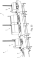
- Figure 20 shows an example of how a pin bone removal apparatus 8 is turned into a pre-rigor and fresh fish pin bone removal apparatus.
- the figure shows the apparatus 8 in closed position, where a conveyor 5 is transporting fish fillets 6 in the direction of processing 9.
- a temperature manipulation unit 11 placed in between a scanner 10 and a pin bone removal unit 12.
- Figure 21 shows an example of how a pin bone removal apparatus 8 is turned into a pre-rigor and fresh fish pin bone removal apparatus.
- the figure shows the apparatus 8 in open position comprising a microwave unit 13.
- Figure 22 shows an example of how a pin bone removal apparatus 8 is turned into a pre-rigor and fresh fish pin bone removal apparatus.
- the figure shows the apparatus 8 in open position comprising a laser unit 14, in open position.
- open position is meant that the cabinet 15 has a hatch 16, a door or a similar device which can be opened and closed.
Landscapes
- Life Sciences & Earth Sciences (AREA)
- Engineering & Computer Science (AREA)
- Wood Science & Technology (AREA)
- Zoology (AREA)
- Food Science & Technology (AREA)
- Processing Of Meat And Fish (AREA)
- Meat, Egg Or Seafood Products (AREA)
Claims (11)
- Appareil de retrait d'arêtes (8) pour retirer des arêtes (2) dans des filets (6) de chair de poisson, l'appareil de retrait d'arêtes (8) comprenant au moinsun convoyeur (5) pour un déplacement des filets (6) vers l'avant en un flux, incluant des étapes pouvant être commandées ou un déplacement continu vers l'avant, les filets étant en mouvement à la fois lors des étapes pouvant être commandées ou lors du déplacement continu vers l'avant, etune unité de retrait d'arêtes (12) comprenant au moins deux mécanismes de traction flexibles (26), les au moins deux mécanismes de traction flexibles (26) comprenant chacun un tambour rotatif (28) agencé sur un bras (27), le bras (27) présentant un certain nombre de moyens de positionnement flexibles (29, 30, 31, 32, 33, 42, 43), qui peuvent réagir aux filets individuels (6) en mouvement, notamment des moyens de déplacement horizontal linéaire (42) pour un positionnement horizontal des tambours rotatifs (28), dans lequelavant l'unité de retrait d'arêtes (12), l'appareil de retrait d'arêtes (8) comprend en outre au moins un scanner (10) pour mesurer les filets individuels (6) afin d'ajuster les tambours rotatifs (28) aux filets individuels (6),- dans lequel le au moins un scanner (10) comprend au moins une unité de positionnement (17) et une unité de détection d'arêtes (18),- dans lequel les au moins deux mécanismes de traction flexibles (26) sont agencés l'un à côté de l'autre et/ou l'un à la suite de l'autre, pouvant réagir aux filets individuels (6) en mouvement,- dans lequel les moyens de positionnement flexible de chaque bras (27) incluent des moyens de déplacement vertical linéaire (29) pour un positionnement vertical du tambour rotatif (28), qui peut réagir aux filets individuels (6) en mouvement,- dans lequel les tambours rotatifs (28) présentent des moyens de positionnement flexibles différents des moyens de positionnement flexibles du bras (27), et- dans lequel les moyens de positionnement flexibles des tambours rotatifs (28) et les moyens de positionnement flexibles du bras (27) peuvent ajuster la position des tambours rotatifs (28) par rapport aux filets individuels (6) en mouvement.
- Appareil de retrait d'arêtes selon la revendication 1, dans lequel les au moins deux mécanismes de traction flexibles (26) sont agencés l'un à la suite de l'autre.
- Appareil de retrait d'arêtes selon l'une quelconque des revendications 1 ou 2, dans lequel l'unité de positionnement (17) est une unité de balayage de surface 3D (17a) et en ce que l'unité de détection d'arêtes (18) est une unité à rayons X (18a).
- Appareil de retrait d'arêtes selon l'une quelconque des revendications 1 ou 2, dans lequel l'unité de positionnement (17) est une unité de balayage de surface 3D (17a) et en ce que l'unité de détection d'arêtes (18) est une unité de balayage MR (18b).
- Appareil de retrait d'arêtes selon l'une quelconque des revendications 1 à 4, dans lequel l'unité de retrait d'arêtes (8) comprend en outre au moins une unité de manipulation de température (11) configurée pour effectuer un chauffage commandé d'au moins une zone sélective de la chair d'un filet de poisson (6) et dans lequel l'unité de manipulation à température commandée (11) comprend une unité à micro-ondes (19), une unité à infrarouge ou une unité à laser (14).
- Appareil de retrait d'arêtes selon la revendication 5, dans lequel au moins l'unité à laser (14) comprend en outre un outil à laser (20) agencé au niveau d'un bras robotique (21).
- Appareil de retrait d'arêtes selon l'une quelconque des revendications 1 à 6, dans lequel l'appareil de retrait d'arêtes (8) comprend une armoire (15, 34) avec des moyens d'auto-nettoyage.
- Appareil de retrait d'arêtes selon la revendication 7, dans lequel les armoires de nettoyage intérieur automatisé (15, 34) comprennent des barres de pulvérisation mobiles et/ou fixes (35).
- Appareil de retrait d'arêtes selon l'une quelconque des revendications 7 à 8, dans lequel les armoires de nettoyage intérieur automatisé (15, 34) comprennent en outre une section de fond inclinée (36).
- Appareil de retrait d'arêtes selon l'une quelconque des revendications 1 à 9, dans lequel les moyens de positionnement flexibles des tambours rotatifs (28) différents des moyens de positionnement flexibles du bras (27) sont au moins certains des moyens de positionnement flexibles suivants : des moyens (31) ajustables en terme d'angle vertical, des moyens (33) ajustables sur 360 degrés ou des moyens (44) pouvant tourner à vitesse variable dans les deux sens autour du centre de rotation du tambour.
- Utilisation d'un appareil de retrait d'arêtes selon l'une quelconque des revendications précédentes 1 à 10, pour enlever des arêtes dans des filets (6) de saumon.
Applications Claiming Priority (3)
| Application Number | Priority Date | Filing Date | Title |
|---|---|---|---|
| DKPA201600456A DK178928B2 (en) | 2016-07-29 | 2016-07-29 | Pre-rigor and fresh fish nerve deboning apparatus |
| DKPA201670625A DK178927B1 (en) | 2016-07-29 | 2016-08-16 | Pin bone removal apparatus |
| PCT/DK2017/050147 WO2018019343A1 (fr) | 2016-07-29 | 2017-05-08 | Appareil de retrait d'arête intramusculaire |
Publications (4)
| Publication Number | Publication Date |
|---|---|
| EP3490384A1 EP3490384A1 (fr) | 2019-06-05 |
| EP3490384A4 EP3490384A4 (fr) | 2020-04-15 |
| EP3490384C0 EP3490384C0 (fr) | 2023-08-09 |
| EP3490384B1 true EP3490384B1 (fr) | 2023-08-09 |
Family
ID=58795918
Family Applications (2)
| Application Number | Title | Priority Date | Filing Date |
|---|---|---|---|
| EP17833618.6A Active EP3490385B1 (fr) | 2016-07-29 | 2017-05-08 | Appareil de retrait d'arête intramusculaire de poisson frais et avant rigidification |
| EP17833617.8A Active EP3490384B1 (fr) | 2016-07-29 | 2017-05-08 | Appareil de retrait d'arête intramusculaire |
Family Applications Before (1)
| Application Number | Title | Priority Date | Filing Date |
|---|---|---|---|
| EP17833618.6A Active EP3490385B1 (fr) | 2016-07-29 | 2017-05-08 | Appareil de retrait d'arête intramusculaire de poisson frais et avant rigidification |
Country Status (5)
| Country | Link |
|---|---|
| EP (2) | EP3490385B1 (fr) |
| CL (2) | CL2019000200A1 (fr) |
| DK (2) | DK178928B2 (fr) |
| PL (2) | PL3490384T3 (fr) |
| WO (2) | WO2018019344A1 (fr) |
Families Citing this family (4)
| Publication number | Priority date | Publication date | Assignee | Title |
|---|---|---|---|---|
| DK3424335T3 (da) | 2017-07-03 | 2023-11-27 | Marel Salmon As | Apparat til fjernelse af nerveben |
| US20230371532A1 (en) * | 2022-03-10 | 2023-11-23 | Circle Seafoods, Inc. | Method and Apparatus for Weakening Pin Bone Attachment in Fish |
| KR102889070B1 (ko) * | 2022-11-09 | 2025-11-25 | 주식회사 참코청하 | 생선살 핀본 제거장치 |
| KR102620401B1 (ko) * | 2023-07-20 | 2024-01-02 | 박진우 | 생선가시를 확인할 수 있도록 된 생선작업장치 |
Citations (1)
| Publication number | Priority date | Publication date | Assignee | Title |
|---|---|---|---|---|
| JP2014014346A (ja) * | 2012-07-05 | 2014-01-30 | Fuji Mach Mfg Co Ltd | 魚の小骨抜き取り機 |
Family Cites Families (20)
| Publication number | Priority date | Publication date | Assignee | Title |
|---|---|---|---|---|
| GB1513243A (en) | 1974-05-14 | 1978-06-07 | Unilever Ltd | Method and apparatus for filleting fish |
| NO754047L (fr) * | 1974-12-04 | 1976-06-08 | Unilever Nv | |
| GB1563662A (en) * | 1977-06-02 | 1980-03-26 | St Clair Fisheries Ltd | Treatment of fish |
| SE467904B (sv) * | 1991-01-18 | 1992-10-05 | Minova Ab | Anordning foer avlaegsnande av ben ur fisk, saerskilt fiskfileer |
| SE509884C2 (sv) * | 1996-10-28 | 1999-03-15 | Kari Koljonen | Anordning för att utdraga ben ur fisk |
| AU3025699A (en) | 1998-04-01 | 1999-11-01 | Kaj Olesen | An apparatus for removing fish bones |
| US6280313B1 (en) | 1998-05-07 | 2001-08-28 | Nordischer Maschinenbau Rud. Baader Gmbh + Co. Kg | Catfish fillet machine |
| WO2001043553A1 (fr) | 1999-12-14 | 2001-06-21 | Carnitech A/S | Procede et appareil servant a retirer les aretes |
| JP2003532393A (ja) * | 2000-05-10 | 2003-11-05 | カルド フィッシュ アクスイェ セルスカプ | 生魚肉製品を製造するための改良された方法 |
| WO2001091637A1 (fr) | 2000-05-29 | 2001-12-06 | Medicotest A/S | Electrode permettant d'etablir un contact electrique avec la peau |
| US6563904B2 (en) | 2000-12-01 | 2003-05-13 | Fmc Technologies, Inc. | Apparatus and method for detecting and removing undesirable material from workpieces |
| JP3738986B2 (ja) * | 2000-12-14 | 2006-01-25 | 株式会社前川製作所 | サケ等大型魚類のピンボーン抜き三枚卸し方法とその装置及びその装置の魚体搬送方法と魚体搬送装置 |
| DE102004024585B3 (de) * | 2004-05-12 | 2005-12-08 | Nordischer Maschinenbau Rud. Baader Gmbh + Co. Kg | Vorrichtung und Verfahren zum Entfernen von Fleischgräten aus einem Fischfilet |
| ATE472939T1 (de) | 2004-11-15 | 2010-07-15 | Prointech S A | Vorrichtung und verfahren zum entgräten von fischen |
| NO328972B1 (no) | 2008-09-26 | 2010-07-05 | Trio Food Proc Machinery As | Fremgangsmate og anordning for a trekke ut pinnebein fra en filet |
| EP2353395A1 (fr) * | 2010-02-07 | 2011-08-10 | Valka Ehf | Appareil de traitement des aliments pour détecter et découper les tissus des articles alimentaires |
| EP2636495A1 (fr) | 2012-03-08 | 2013-09-11 | Marel Iceland EHF | Appareil de découpe permettant de couper des articles alimentaires transportés sur un convoyeur comprenant au moins une bande transporteuse ainsi que système de traitement de produits alimentaires comprenant un tel appareil |
| NO20140037A1 (no) * | 2014-01-13 | 2014-12-01 | Unotek Breiland | En fremgangsmåte for fjerning av tykkfiskbein fra hvitfisk filet |
| US9848611B2 (en) * | 2014-07-15 | 2017-12-26 | Marel Iceland Ehf | Pin bone removal system |
| DE102015111448B3 (de) * | 2015-07-15 | 2016-05-25 | Nordischer Maschinenbau Rud. Baader Gmbh + Co. Kg | Vorrichtung und Verfahren zum Entfernen von Fleischgräten aus einem Fischfilet |
-
2016
- 2016-07-29 DK DKPA201600456A patent/DK178928B2/en active IP Right Maintenance
- 2016-08-16 DK DKPA201670625A patent/DK178927B1/en not_active IP Right Cessation
-
2017
- 2017-05-08 WO PCT/DK2017/050148 patent/WO2018019344A1/fr not_active Ceased
- 2017-05-08 PL PL17833617.8T patent/PL3490384T3/pl unknown
- 2017-05-08 EP EP17833618.6A patent/EP3490385B1/fr active Active
- 2017-05-08 EP EP17833617.8A patent/EP3490384B1/fr active Active
- 2017-05-08 PL PL17833618.6T patent/PL3490385T3/pl unknown
- 2017-05-08 WO PCT/DK2017/050147 patent/WO2018019343A1/fr not_active Ceased
-
2019
- 2019-01-25 CL CL2019000200A patent/CL2019000200A1/es unknown
- 2019-01-25 CL CL2019000201A patent/CL2019000201A1/es unknown
Patent Citations (1)
| Publication number | Priority date | Publication date | Assignee | Title |
|---|---|---|---|---|
| JP2014014346A (ja) * | 2012-07-05 | 2014-01-30 | Fuji Mach Mfg Co Ltd | 魚の小骨抜き取り機 |
Also Published As
| Publication number | Publication date |
|---|---|
| EP3490384C0 (fr) | 2023-08-09 |
| WO2018019344A1 (fr) | 2018-02-01 |
| EP3490385A4 (fr) | 2020-04-15 |
| DK178928B2 (en) | 2023-05-15 |
| EP3490384A1 (fr) | 2019-06-05 |
| DK178928B1 (en) | 2017-06-06 |
| CL2019000200A1 (es) | 2019-07-12 |
| DK201670625A1 (en) | 2017-06-06 |
| DK178927B1 (en) | 2017-06-06 |
| CL2019000201A1 (es) | 2019-07-12 |
| EP3490385A1 (fr) | 2019-06-05 |
| EP3490384A4 (fr) | 2020-04-15 |
| EP3490385C0 (fr) | 2023-06-07 |
| DK201600456A1 (en) | 2017-06-06 |
| PL3490385T3 (pl) | 2023-11-13 |
| WO2018019343A1 (fr) | 2018-02-01 |
| PL3490384T3 (pl) | 2023-12-11 |
| EP3490385B1 (fr) | 2023-06-07 |
Similar Documents
| Publication | Publication Date | Title |
|---|---|---|
| EP3490384B1 (fr) | Appareil de retrait d'arête intramusculaire | |
| US10485242B2 (en) | Sensor-guided automated method and system for processing crustaceans | |
| US20140227953A1 (en) | Method for removing blood released during filleting from the backbone of fish, and device for removing such blood | |
| US10130107B2 (en) | Processing device for processing slaughtered and plucked poultry carcasses, comprising poultry-support devices and poultry-processing devices | |
| DK179619B1 (en) | GUTTING DEVICE AND METHOD FOR GUTTING FISH | |
| EP3160241B1 (fr) | Procédé et appareil d'élimination de corps étrangers dans des morceaux de produit alimentaire | |
| JPS59169441A (ja) | 屠殺家禽の胸肉片取外し装置 | |
| EP0512636B1 (fr) | Procédé et dispositif pour l'éviscération mécanique de volailles abattues | |
| US9357789B2 (en) | Method for mechanically removing pin bones from fillet parts of conveyed fish and device for performing said method | |
| US20180084793A1 (en) | Cutting device and a cutting system for cutting food products | |
| EP4075988B1 (fr) | Système de traitement de viande | |
| CA2537453C (fr) | Procede de commande d'un traitement mecanique de poissons blancs a tetes tranchees et vides, et dispositif pour la mise en oeuvre de ce procede | |
| AU2020405625C8 (en) | A meat processing system | |
| US20250120410A1 (en) | Autonomous robotic bone dust scraper | |
| CN120225061A (zh) | 组合式多视觉自动化切割系统 | |
| NZ626747B2 (en) | Method for mechanically removing pin bones from filet parts of conveyed fish and device for performing said method |
Legal Events
| Date | Code | Title | Description |
|---|---|---|---|
| STAA | Information on the status of an ep patent application or granted ep patent |
Free format text: STATUS: THE INTERNATIONAL PUBLICATION HAS BEEN MADE |
|
| PUAI | Public reference made under article 153(3) epc to a published international application that has entered the european phase |
Free format text: ORIGINAL CODE: 0009012 |
|
| STAA | Information on the status of an ep patent application or granted ep patent |
Free format text: STATUS: REQUEST FOR EXAMINATION WAS MADE |
|
| 17P | Request for examination filed |
Effective date: 20190226 |
|
| AK | Designated contracting states |
Kind code of ref document: A1 Designated state(s): AL AT BE BG CH CY CZ DE DK EE ES FI FR GB GR HR HU IE IS IT LI LT LU LV MC MK MT NL NO PL PT RO RS SE SI SK SM TR |
|
| AX | Request for extension of the european patent |
Extension state: BA ME |
|
| DAV | Request for validation of the european patent (deleted) | ||
| DAX | Request for extension of the european patent (deleted) | ||
| A4 | Supplementary search report drawn up and despatched |
Effective date: 20200313 |
|
| RIC1 | Information provided on ipc code assigned before grant |
Ipc: A22C 25/16 20060101AFI20200309BHEP |
|
| STAA | Information on the status of an ep patent application or granted ep patent |
Free format text: STATUS: EXAMINATION IS IN PROGRESS |
|
| 17Q | First examination report despatched |
Effective date: 20211206 |
|
| GRAP | Despatch of communication of intention to grant a patent |
Free format text: ORIGINAL CODE: EPIDOSNIGR1 |
|
| STAA | Information on the status of an ep patent application or granted ep patent |
Free format text: STATUS: GRANT OF PATENT IS INTENDED |
|
| INTG | Intention to grant announced |
Effective date: 20230323 |
|
| GRAS | Grant fee paid |
Free format text: ORIGINAL CODE: EPIDOSNIGR3 |
|
| GRAA | (expected) grant |
Free format text: ORIGINAL CODE: 0009210 |
|
| STAA | Information on the status of an ep patent application or granted ep patent |
Free format text: STATUS: THE PATENT HAS BEEN GRANTED |
|
| AK | Designated contracting states |
Kind code of ref document: B1 Designated state(s): AL AT BE BG CH CY CZ DE DK EE ES FI FR GB GR HR HU IE IS IT LI LT LU LV MC MK MT NL NO PL PT RO RS SE SI SK SM TR |
|
| REG | Reference to a national code |
Ref country code: GB Ref legal event code: FG4D |
|
| REG | Reference to a national code |
Ref country code: CH Ref legal event code: EP |
|
| REG | Reference to a national code |
Ref country code: DE Ref legal event code: R096 Ref document number: 602017072574 Country of ref document: DE |
|
| REG | Reference to a national code |
Ref country code: IE Ref legal event code: FG4D |
|
| U01 | Request for unitary effect filed |
Effective date: 20230828 |
|
| U07 | Unitary effect registered |
Designated state(s): AT BE BG DE DK EE FI FR IT LT LU LV MT NL PT SE SI Effective date: 20230904 |
|
| REG | Reference to a national code |
Ref country code: NO Ref legal event code: T2 Effective date: 20230809 |
|
| PG25 | Lapsed in a contracting state [announced via postgrant information from national office to epo] |
Ref country code: GR Free format text: LAPSE BECAUSE OF FAILURE TO SUBMIT A TRANSLATION OF THE DESCRIPTION OR TO PAY THE FEE WITHIN THE PRESCRIBED TIME-LIMIT Effective date: 20231110 |
|
| PG25 | Lapsed in a contracting state [announced via postgrant information from national office to epo] |
Ref country code: RS Free format text: LAPSE BECAUSE OF FAILURE TO SUBMIT A TRANSLATION OF THE DESCRIPTION OR TO PAY THE FEE WITHIN THE PRESCRIBED TIME-LIMIT Effective date: 20230809 Ref country code: HR Free format text: LAPSE BECAUSE OF FAILURE TO SUBMIT A TRANSLATION OF THE DESCRIPTION OR TO PAY THE FEE WITHIN THE PRESCRIBED TIME-LIMIT Effective date: 20230809 Ref country code: GR Free format text: LAPSE BECAUSE OF FAILURE TO SUBMIT A TRANSLATION OF THE DESCRIPTION OR TO PAY THE FEE WITHIN THE PRESCRIBED TIME-LIMIT Effective date: 20231110 |
|
| PG25 | Lapsed in a contracting state [announced via postgrant information from national office to epo] |
Ref country code: ES Free format text: LAPSE BECAUSE OF FAILURE TO SUBMIT A TRANSLATION OF THE DESCRIPTION OR TO PAY THE FEE WITHIN THE PRESCRIBED TIME-LIMIT Effective date: 20230809 |
|
| PG25 | Lapsed in a contracting state [announced via postgrant information from national office to epo] |
Ref country code: SM Free format text: LAPSE BECAUSE OF FAILURE TO SUBMIT A TRANSLATION OF THE DESCRIPTION OR TO PAY THE FEE WITHIN THE PRESCRIBED TIME-LIMIT Effective date: 20230809 Ref country code: RO Free format text: LAPSE BECAUSE OF FAILURE TO SUBMIT A TRANSLATION OF THE DESCRIPTION OR TO PAY THE FEE WITHIN THE PRESCRIBED TIME-LIMIT Effective date: 20230809 Ref country code: ES Free format text: LAPSE BECAUSE OF FAILURE TO SUBMIT A TRANSLATION OF THE DESCRIPTION OR TO PAY THE FEE WITHIN THE PRESCRIBED TIME-LIMIT Effective date: 20230809 Ref country code: CZ Free format text: LAPSE BECAUSE OF FAILURE TO SUBMIT A TRANSLATION OF THE DESCRIPTION OR TO PAY THE FEE WITHIN THE PRESCRIBED TIME-LIMIT Effective date: 20230809 Ref country code: SK Free format text: LAPSE BECAUSE OF FAILURE TO SUBMIT A TRANSLATION OF THE DESCRIPTION OR TO PAY THE FEE WITHIN THE PRESCRIBED TIME-LIMIT Effective date: 20230809 |
|
| REG | Reference to a national code |
Ref country code: DE Ref legal event code: R097 Ref document number: 602017072574 Country of ref document: DE |
|
| U20 | Renewal fee for the european patent with unitary effect paid |
Year of fee payment: 8 Effective date: 20240416 |
|
| PLBE | No opposition filed within time limit |
Free format text: ORIGINAL CODE: 0009261 |
|
| STAA | Information on the status of an ep patent application or granted ep patent |
Free format text: STATUS: NO OPPOSITION FILED WITHIN TIME LIMIT |
|
| 26N | No opposition filed |
Effective date: 20240513 |
|
| REG | Reference to a national code |
Ref country code: CH Ref legal event code: PL |
|
| PG25 | Lapsed in a contracting state [announced via postgrant information from national office to epo] |
Ref country code: MC Free format text: LAPSE BECAUSE OF FAILURE TO SUBMIT A TRANSLATION OF THE DESCRIPTION OR TO PAY THE FEE WITHIN THE PRESCRIBED TIME-LIMIT Effective date: 20230809 |
|
| PG25 | Lapsed in a contracting state [announced via postgrant information from national office to epo] |
Ref country code: MC Free format text: LAPSE BECAUSE OF FAILURE TO SUBMIT A TRANSLATION OF THE DESCRIPTION OR TO PAY THE FEE WITHIN THE PRESCRIBED TIME-LIMIT Effective date: 20230809 Ref country code: CH Free format text: LAPSE BECAUSE OF NON-PAYMENT OF DUE FEES Effective date: 20240531 |
|
| PGFP | Annual fee paid to national office [announced via postgrant information from national office to epo] |
Ref country code: IS Payment date: 20250327 Year of fee payment: 9 |
|
| PG25 | Lapsed in a contracting state [announced via postgrant information from national office to epo] |
Ref country code: IE Free format text: LAPSE BECAUSE OF NON-PAYMENT OF DUE FEES Effective date: 20240508 |
|
| PGFP | Annual fee paid to national office [announced via postgrant information from national office to epo] |
Ref country code: NO Payment date: 20250328 Year of fee payment: 9 |
|
| PGFP | Annual fee paid to national office [announced via postgrant information from national office to epo] |
Ref country code: GB Payment date: 20250327 Year of fee payment: 9 |
|
| U20 | Renewal fee for the european patent with unitary effect paid |
Year of fee payment: 9 Effective date: 20250327 |
|
| PGFP | Annual fee paid to national office [announced via postgrant information from national office to epo] |
Ref country code: PL Payment date: 20250331 Year of fee payment: 9 |
|
| PG25 | Lapsed in a contracting state [announced via postgrant information from national office to epo] |
Ref country code: CY Free format text: LAPSE BECAUSE OF FAILURE TO SUBMIT A TRANSLATION OF THE DESCRIPTION OR TO PAY THE FEE WITHIN THE PRESCRIBED TIME-LIMIT; INVALID AB INITIO Effective date: 20170508 |
|
| PG25 | Lapsed in a contracting state [announced via postgrant information from national office to epo] |
Ref country code: HU Free format text: LAPSE BECAUSE OF FAILURE TO SUBMIT A TRANSLATION OF THE DESCRIPTION OR TO PAY THE FEE WITHIN THE PRESCRIBED TIME-LIMIT; INVALID AB INITIO Effective date: 20170508 |