EP3494262B1 - Rohrleitungssteuerungssystem, -verfahren und -vorrichtung zur verhinderung einer wiederholten verwendung eines geräts mit rückmeldung - Google Patents
Rohrleitungssteuerungssystem, -verfahren und -vorrichtung zur verhinderung einer wiederholten verwendung eines geräts mit rückmeldung Download PDFInfo
- Publication number
- EP3494262B1 EP3494262B1 EP17849506.5A EP17849506A EP3494262B1 EP 3494262 B1 EP3494262 B1 EP 3494262B1 EP 17849506 A EP17849506 A EP 17849506A EP 3494262 B1 EP3494262 B1 EP 3494262B1
- Authority
- EP
- European Patent Office
- Prior art keywords
- valve
- time period
- indicator
- request
- actuator
- Prior art date
- Legal status (The legal status is an assumption and is not a legal conclusion. Google has not performed a legal analysis and makes no representation as to the accuracy of the status listed.)
- Active
Links
Images


Classifications
-
- A—HUMAN NECESSITIES
- A61—MEDICAL OR VETERINARY SCIENCE; HYGIENE
- A61N—ELECTROTHERAPY; MAGNETOTHERAPY; RADIATION THERAPY; ULTRASOUND THERAPY
- A61N1/00—Electrotherapy; Circuits therefor
- A61N1/18—Applying electric currents by contact electrodes
- A61N1/32—Applying electric currents by contact electrodes alternating or intermittent currents
- A61N1/38—Applying electric currents by contact electrodes alternating or intermittent currents for producing shock effects
- A61N1/39—Heart defibrillators
- A61N1/3987—Heart defibrillators characterised by the timing or triggering of the shock
-
- A—HUMAN NECESSITIES
- A61—MEDICAL OR VETERINARY SCIENCE; HYGIENE
- A61B—DIAGNOSIS; SURGERY; IDENTIFICATION
- A61B5/00—Measuring for diagnostic purposes; Identification of persons
- A61B5/24—Detecting, measuring or recording bioelectric or biomagnetic signals of the body or parts thereof
- A61B5/316—Modalities, i.e. specific diagnostic methods
- A61B5/318—Heart-related electrical modalities, e.g. electrocardiography [ECG]
- A61B5/346—Analysis of electrocardiograms
- A61B5/349—Detecting specific parameters of the electrocardiograph cycle
- A61B5/361—Detecting fibrillation
-
- A—HUMAN NECESSITIES
- A61—MEDICAL OR VETERINARY SCIENCE; HYGIENE
- A61B—DIAGNOSIS; SURGERY; IDENTIFICATION
- A61B5/00—Measuring for diagnostic purposes; Identification of persons
- A61B5/48—Other medical applications
- A61B5/4836—Diagnosis combined with treatment in closed-loop systems or methods
-
- A—HUMAN NECESSITIES
- A61—MEDICAL OR VETERINARY SCIENCE; HYGIENE
- A61B—DIAGNOSIS; SURGERY; IDENTIFICATION
- A61B5/00—Measuring for diagnostic purposes; Identification of persons
- A61B5/72—Signal processing specially adapted for physiological signals or for diagnostic purposes
- A61B5/7203—Signal processing specially adapted for physiological signals or for diagnostic purposes for noise prevention, reduction or removal
- A61B5/7217—Signal processing specially adapted for physiological signals or for diagnostic purposes for noise prevention, reduction or removal of noise originating from a therapeutic or surgical apparatus, e.g. from a pacemaker
-
- A—HUMAN NECESSITIES
- A61—MEDICAL OR VETERINARY SCIENCE; HYGIENE
- A61N—ELECTROTHERAPY; MAGNETOTHERAPY; RADIATION THERAPY; ULTRASOUND THERAPY
- A61N1/00—Electrotherapy; Circuits therefor
- A61N1/18—Applying electric currents by contact electrodes
- A61N1/32—Applying electric currents by contact electrodes alternating or intermittent currents
- A61N1/38—Applying electric currents by contact electrodes alternating or intermittent currents for producing shock effects
- A61N1/39—Heart defibrillators
- A61N1/3904—External heart defibrillators [EHD]
-
- A—HUMAN NECESSITIES
- A61—MEDICAL OR VETERINARY SCIENCE; HYGIENE
- A61N—ELECTROTHERAPY; MAGNETOTHERAPY; RADIATION THERAPY; ULTRASOUND THERAPY
- A61N1/00—Electrotherapy; Circuits therefor
- A61N1/18—Applying electric currents by contact electrodes
- A61N1/32—Applying electric currents by contact electrodes alternating or intermittent currents
- A61N1/38—Applying electric currents by contact electrodes alternating or intermittent currents for producing shock effects
- A61N1/39—Heart defibrillators
- A61N1/3925—Monitoring; Protecting
-
- A—HUMAN NECESSITIES
- A61—MEDICAL OR VETERINARY SCIENCE; HYGIENE
- A61N—ELECTROTHERAPY; MAGNETOTHERAPY; RADIATION THERAPY; ULTRASOUND THERAPY
- A61N1/00—Electrotherapy; Circuits therefor
- A61N1/18—Applying electric currents by contact electrodes
- A61N1/32—Applying electric currents by contact electrodes alternating or intermittent currents
- A61N1/38—Applying electric currents by contact electrodes alternating or intermittent currents for producing shock effects
- A61N1/39—Heart defibrillators
- A61N1/3993—User interfaces for automatic external defibrillators
-
- E—FIXED CONSTRUCTIONS
- E03—WATER SUPPLY; SEWERAGE
- E03D—WATER-CLOSETS OR URINALS WITH FLUSHING DEVICES; FLUSHING VALVES THEREFOR
- E03D5/00—Special constructions of flushing devices, e.g. closed flushing system
- E03D5/02—Special constructions of flushing devices, e.g. closed flushing system operated mechanically or hydraulically (or pneumatically) also details such as push buttons, levers and pull-card therefor
- E03D5/026—Devices preventing overflow or locks inhibiting the use of the flushing system ; Devices preventing sucking-up of sealing and flushing water
-
- E—FIXED CONSTRUCTIONS
- E03—WATER SUPPLY; SEWERAGE
- E03D—WATER-CLOSETS OR URINALS WITH FLUSHING DEVICES; FLUSHING VALVES THEREFOR
- E03D5/00—Special constructions of flushing devices, e.g. closed flushing system
- E03D5/02—Special constructions of flushing devices, e.g. closed flushing system operated mechanically or hydraulically (or pneumatically) also details such as push buttons, levers and pull-card therefor
- E03D5/09—Special constructions of flushing devices, e.g. closed flushing system operated mechanically or hydraulically (or pneumatically) also details such as push buttons, levers and pull-card therefor directly by the hand
-
- E—FIXED CONSTRUCTIONS
- E03—WATER SUPPLY; SEWERAGE
- E03D—WATER-CLOSETS OR URINALS WITH FLUSHING DEVICES; FLUSHING VALVES THEREFOR
- E03D5/00—Special constructions of flushing devices, e.g. closed flushing system
- E03D5/10—Special constructions of flushing devices, e.g. closed flushing system operated electrically, e.g. by a photo-cell; also combined with devices for opening or closing shutters in the bowl outlet and/or with devices for raising/or lowering seat and cover and/or for swiveling the bowl
- E03D5/105—Special constructions of flushing devices, e.g. closed flushing system operated electrically, e.g. by a photo-cell; also combined with devices for opening or closing shutters in the bowl outlet and/or with devices for raising/or lowering seat and cover and/or for swiveling the bowl touchless, e.g. using sensors
-
- F—MECHANICAL ENGINEERING; LIGHTING; HEATING; WEAPONS; BLASTING
- F16—ENGINEERING ELEMENTS AND UNITS; GENERAL MEASURES FOR PRODUCING AND MAINTAINING EFFECTIVE FUNCTIONING OF MACHINES OR INSTALLATIONS; THERMAL INSULATION IN GENERAL
- F16K—VALVES; TAPS; COCKS; ACTUATING-FLOATS; DEVICES FOR VENTING OR AERATING
- F16K37/00—Special means in or on valves or other cut-off apparatus for indicating or recording operation thereof, or for enabling an alarm to be given
- F16K37/0025—Electrical or magnetic means
-
- G—PHYSICS
- G08—SIGNALLING
- G08B—SIGNALLING SYSTEMS, e.g. PERSONAL CALLING SYSTEMS; ORDER TELEGRAPHS; ALARM SYSTEMS
- G08B21/00—Alarms responsive to a single specified undesired or abnormal condition and not otherwise provided for
- G08B21/18—Status alarms
- G08B21/182—Level alarms, e.g. alarms responsive to variables exceeding a threshold
-
- G—PHYSICS
- G08—SIGNALLING
- G08B—SIGNALLING SYSTEMS, e.g. PERSONAL CALLING SYSTEMS; ORDER TELEGRAPHS; ALARM SYSTEMS
- G08B5/00—Visible signalling systems, e.g. visible personal calling systems or remote indication of seats occupied
- G08B5/22—Visible signalling systems, e.g. visible personal calling systems or remote indication of seats occupied using electric transmission; using electromagnetic transmission
- G08B5/36—Visible signalling systems, e.g. visible personal calling systems or remote indication of seats occupied using electric transmission; using electromagnetic transmission using visible light sources
Definitions
- This invention relates generally to restroom appliances and valves and, in particular, to an apparatus, a system and a method for preventing repeated use of a restroom appliance through visual feedback.
- Fluid control systems are used to manage and regulate the flow of fluid through plumbing systems, allowing and preventing fluid flow to and through various plumbing fixtures.
- control systems are used to regulate flow through toilets and lavatories in a facility, such as a prison.
- Prior art plumbing control systems include a plurality of toilets and lavatories within a facility, each of which are integrated through an associated controller, which, in turn, communicates with a central controller.
- each toilet and lavatory typically include a solenoid valve to operate the fixture based on use of an actuator.
- the control system uses the central controller to receive requests from any individual fixture, process the request, and communicate an appropriate signal back to the logic circuit or controller associated with each fixture, either allowing or disallowing fluid flow through a flow valve.
- these plumbing control systems can be used to delay operation of a single fixture, e.g., a flush valve for a toilet, within the facility, and/or to prevent such a fixture from being operated more than a specified number of times within a predetermined time period, thereby preventing flooding of the toilet.
- a single fixture e.g., a flush valve for a toilet
- these systems are classified as “delay” and/or "lockout” systems.
- U.S. Pat. No. 4,985,944 to Shaw is directed to a plumbing control system and method for prisons, which causes operation of a valve to be delayed for a selected period after the sensor has been operated and limits the number of operations of the valve per unit time.
- the users of the restroom appliances including fixtures having such "delay” and/or "lockout” features may not be aware of previous uses by others and, as a result, may not be aware if the restroom appliance is currently usable or locked out, if the next usage of the restroom appliance will create a lockout, or if the restroom appliance has been reset and is capable of more than a single usage during a time period.
- one restroom appliance may be shared by multiple individuals.
- a subsequent user may be unaware of whether the restroom appliance can be used or, if it can be used, how many additional times it can be used before it is placed in a "lockout" mode.
- a first inmate uses a toilet and flushes twice, and the maximum number of flushes within a time period is three
- a second inmate may approach the toilet within the time period thinking that three flushes are available.
- the second inmate may unknowingly only have one flush available before the valve prevents any further usage. In this situation, if the second inmate flushes before or during his usage of the toilet, the unavailability of an additional flush may result in waste being left in the toilet bowl.
- the terms "communication” and "communicate” refer to the receipt or transfer of one or more signals, messages, commands, or other type of data.
- one unit or component to be in communication with another unit or component means that the one unit or component is able to directly or indirectly receive data from and/or transmit data to the other unit or component. This can refer to a direct or indirect connection that may be wired and/or wireless in nature.
- two units or components may be in communication with each other even though the data transmitted may be modified, processed, and/or routed between the first and second unit or component.
- a first unit may be in communication with a second unit even though the first unit passively receives data and does not actively transmit data to the second unit.
- a first unit may be in communication with a second unit if an intermediary unit processes data from one unit and transmits processed data to the second unit. It will be appreciated that numerous other arrangements are possible.
- a restroom appliance such as a toilet, shower, faucet, and/or the like, includes a plumbing fixture, such as a valve, configured to control flow of a fluid to, from, and/or within the restroom appliance.
- the valve controls the flow of fluid through at least one valve operation, which may include opening the valve, closing the valve, restricting the flow of fluid through the valve, and/or the like, using a solenoid or any other like mechanism.
- a controller is configured to prevent a user of the restroom appliance from overloading the plumbing system and/or overusing the restroom appliance by limiting usage of the restroom appliance to a predetermined number of uses within a time period.
- An indicator configured to display a plurality of different visual states provides a user with a current status of the restroom appliance, such as whether it is available for full usage (e.g., the predetermined number of uses are all available), available for limited usage (e.g., less than the predetermined number of uses are left within a time period), or "locked out" and unavailable for any further uses for a time period.
- a restroom appliance refers to any type of appliance that is provided with fluid via one or more valves.
- a restroom appliance may include, for example, a toilet, faucet, shower, and/or the like.
- a valve refers to any type of valve capable of providing, controlling, and/or restricting the flow of a fluid to, from, and/or within a restroom appliance.
- a valve may include a flush valve for a toilet, a shower valve for a shower, a faucet valve for a faucet, or any other type of mechanism for providing, controlling, and/or restricting fluid flow.
- a valve includes a solenoid that operates the valve to open, close, and/or restrict the flow of water in response to one or more commands received from a controller.
- the system 1000 includes restroom appliances 117, 119, 121, 123 each having a respective valve 116, 118, 120, 122 and a respective controller 124, 126, 128, 130 . It will appreciated that each controller may also control one or more valves of other plumbing appliances and that, in some examples, a single controller may be used.
- the controllers 124, 126, 128, 130 may be located directly on the valves 116, 118, 120, 122 or at some other location (e.g., in a chase area, behind an appliance or wall, and/or the like).
- the controllers 124, 126, 128, 130 for each respective valve are in communication with a central controller 132 .
- a central controller 132 or a single local controller may be used instead of each of the respective controllers 124, 126, 128, 130 and that, in some examples, a central controller 132 may not be used.
- the controllers 124, 126, 128, 130 may have stored thereon, or be in communication with, program instructions that, when executed by a controller, cause the controller to perform data processing tasks.
- a computer-readable medium may be memory located on or in communication with a controller for storing the program instructions.
- controller refers to one or more of any type of processor, microprocessor, computer system, logic circuit, and/or other like data processing devices. Further, the term controller, unless noted otherwise, may refer to one or more controllers that are local to a specific restroom appliance, local to a plurality of restroom appliances or facility, and/or remote from the restroom appliances or facility. For example, a controller may be incorporated into a valve or restroom appliance, separate from a valve or restroom appliance, and/or arranged as a central controller that communicates with controllers local to the valves and restroom appliances. Various other arrangements are possible.
- the central controller 132 is in communication with a data storage device 134 to store usage data concerning the restroom appliances 117,119, 121,123 and/or the associated valves 116, 118, 120, 122 .
- Each restroom appliance 117,119, 121, 123 , valve 116, 118, 120, 122 , and/or the associated controllers 124, 126, 128, 130 may also include a data storage device, such as memory, to store usage data.
- Usage data may include, for example, a counter representing a number of times that a particular restroom appliance has been used and/or a number of valve operations performed by a particular valve. Usage data may be specific to a time period, e.g., a number of uses within a specified time period, and/or may represent an aggregate number of uses.
- the restroom appliance 117 includes an actuator 203 .
- the actuator 203 may be, for example, a push button, a capacitance sensor, a lever, an infrared sensor, and/or any other like mechanism for requesting a valve operation.
- the actuator 203 is in communication with the controller 124 associated with the restroom appliance 117 and/or a central controller (not shown in FIG. 2 ).
- the restroom appliance 117 is a toilet and the actuator 203 is used to request a flush.
- the restroom appliance 117 also includes one or more visual indicators 205 , such as a display screen, light emitting diode (LED), and/or the like.
- the actuator 203 includes the indicator 205 .
- indicator(s) 205 may be arranged on or off the restroom appliance 117 at any suitable location such that a prospective user of the restroom appliance 117 is able to view it.
- one or more indicators 205 may be arranged on the side of the restroom appliance 117 , adjacent the actuator 203 , or on a wall adjacent the restroom appliance 117 .
- non-visual indicators may be used, such as audible alarms or tactile feedback.
- a non-visual indicator may be a speaker in communication with a controller 124 to provide one or more audible indications to a user.
- a first audible state indicating that the restroom appliance 117 has not been recently used, may be the absence of any audible sound.
- a second audible state indicating that the restroom appliance 117 has been used within a predetermined time period, may be, for example, a tone such as a "beep" or "click.”
- the audible indication may be presented as a pattern of tones to indicate a number of uses that have already occurred or a number of uses that are left before lockout.
- the second audible state may be a repeating pattern of two "beeps" or other tones, followed by a pause, and a next audible state may be a repeating pattern of a single "beep” or other tone.
- a lockout audible state may be an alarm, a continuous tone, a rapid succession of "beeps," and/or the like.
- the audible states may also be distinguished based on a change in volume, tone, pitch, and/or the like. For example, a different tone may be used for different audible states. It will be appreciated that various other sound and/or tonal patterns may be used.
- the controller 124 may be programmed or configured to permit only a maximum number of valve operations within a given time period. For example, the controller 124 may maintain one or more programmatic counters and timers and permit three valve operations within five minutes. After the maximum number of valve operations has been reached, the controller 124 may prevent further valve operations when requested through use of the actuator 203 . In one example, the controller 124 may prevent further activation of the valve 116 until the time period elapses (e.g., five minutes from the first use when a first timer is initiated). In another example, the controller 124 may, in response to reaching the maximum number of valve operations during the time period, prevent further valve operations for an additional lockout time period (e.g., a second time period). Thus, instead of only preventing further use of the valve 116 until the first time period elapses, the controller 124 may, in response to reaching the maximum number of valve operations, initiate a second timer during which additional valve operations are not permitted.
- the controller 124 may, in response to reaching the maximum number of
- the controller 124 may prevent additional usage of the valve by not responding to requests received through the actuator 203 once the maximum number of uses has been reached.
- the controller 124 may determine if a timer is currently operating. If not, the controller 124 can begin a first timer, initiate a counter and set it to 1, and cause the requested valve operation. If an initial timer is currently operating when a request is received, the controller 124 can then determine if the counter has reached the maximum number of uses (e.g., if the counter value is equal to the maximum number of valve operations). If the maximum number of uses has not been reached, the counter is incremented and the controller 124 sends a command to the valve 116 to cause the requested valve operation.
- the visual indicator 205 is configured to display at least three different visual states.
- first visual state refers to different visual states that may be displayed in any order. The numbering of the visual state does not mean that it is necessarily displayed in that order.
- a first visual state may be a baseline state in which the restroom appliance may be used. The first visual state may indicate that a maximum number of valve operations are available for the user of the restroom appliance (e.g., that the restroom appliance has not been used by another within a certain time period).
- the first visual state may be a steady green light.
- the first visual state may be a static state with no further indication provided, such as no light being displayed.
- a second visual state may indicate that one or more valve operations have already been performed but that the maximum number of uses have not yet been reached.
- the second visual state may indicate to a user that the maximum number of uses are no longer available without waiting additional time, but at least one use is still available. For example, if the maximum number of uses is three, the second visual state may be displayed after the first use or after the second use.
- the second visual state may be, for example, a flashing green or red light.
- a third (or fourth, fifth, etc., depending on the maximum number of valve operations) visual state may be a lockout state that indicates that additional valve operations will not be permitted.
- the third visual state may be, for example, a steady red light. It will be appreciated that numerous different visual states may be used and that the visual states may include any pattern of steady, flashing, and/or different colored lights. Further, the different visual states may also be textually displayed on a display screen, an icon displayed on a display screen, and/or the like. In yet another example, there may be separate indicators for each visual state, such as an array of LEDs where a different LED is lit with each valve operation until the maximum number of valve operations is reached.
- a flashing light refers to a light that repeatedly turns on and off, or repeatedly changes color, at any time interval.
- a flashing light may be a light that is turned on for a first time period, turned off for a second time period, and then repeats the pattern.
- additional visual states may be presented prior to the lockout state.
- the visual states may indicate how many uses have already been requested or how many uses are left.
- a second visual state may be displayed in response to the first valve operation or request indicating that two additional valve operations are available within the time period.
- This visual state may be, for example, a red light that flashes twice, pauses, and continues to flash twice between pauses.
- the next visual state may be, for example, a red light that flashes once between pauses to indicate that only a single valve operation is available.
- an actuator 201 is shown according to preferred and non-limiting embodiments.
- the actuator 201 is a push button or a capacitance sensor and is surrounded by an indicator 301.
- the indicator 301 in this example is a ring that surrounds the actuator 201 and is capable of displaying multiple visual states including, for example, different colors and/or different lighting patterns.
- the indicator 301 may include one or more LEDs and/or other lighting devices.
- the actuator 201 is shown to include an indicator 301 , a push button 303 , and an outer rim 305 .
- the outer rim 305 may be any suitable material, such as stainless steel, plastic, and/or the like.
- the push button 303 physically depresses upon user actuation, closing a switch that underlies the actuator 201.
- the actuator 201 may be transparent or translucent and the indicator 301 may be positioned behind it such that the actuator 201 and indicator 301 are integrated.
- Various other arrangements are possible.
- a method for preventing repeated use of a restroom appliance with visual feedback is shown according to a preferred and non-limiting embodiment.
- a programmatic counter is initiated and set to zero (0).
- a first visual state is displayed by the visual indicator(s) to indicate to a user that the maximum number of valve operations are available.
- a request is received to utilize the restroom appliance. For example, a user may use an actuator to request a valve operation.
- the requested valve operation is performed at step 407 and a timer is started at step 409 . In a preferred and non-limiting example, the timer is set for 5 minutes, although various other times may be used.
- step 411 the counter is incremented.
- step 413 a next request to utilize the restroom appliance is received.
- the next visual state may be a second, third, fourth, or further visual state, depending on the value of the counter and/or number of requests.
- the method then goes back to step 411 in which the counter is incremented. If the maximum number of valve operations have been reached, however, the method proceeds from step 417 to step 420 , in which a lockout visual state is displayed (e.g., a third, fourth, or further visual state), and then to step 421 , in which further valve operations are prevented for a time period (e.g., either the remaining duration of the first time period or the duration of a second time period).
- a lockout visual state e.g., a third, fourth, or further visual state
- a method for preventing repeated use of a restroom appliance with visual feedback is shown according to another preferred and non-limiting embodiment.
- the first several steps are similar to those shown in FIG. 4 .
- a programmatic counter is initiated and set to zero (0).
- a first visual state is displayed by the visual indicator(s) to indicate to a user that the maximum number of valve operations are available.
- a request is received to utilize the restroom appliance. For example, a user may activate an actuator to cause a valve operation.
- the requested valve operation is performed at step 507 and a first timer is started at step 509 .
- the counter is incremented.
- a next request to utilize the restroom appliance is received.
- the next visual state may be a second, third, fourth, or further visual state, depending on the value of the counter and/or number of requests.
- step 511 the method then goes back to step 511 in which the counter is incremented. If the maximum number of valve operations have been reached, however, the method proceeds to step 521 , in which a second timer is started for a second time period (e.g., a lockout period), then to step 522 , in which a lockout visual state is displayed (e.g., a third, fourth, or further visual state), and finally to step 523 , in which further valve operations are prevented for the second time period.
- step 525 it is determined whether the second time period has elapsed. Once the second time period elapses, the method returns to step 501 and the counter is reset.
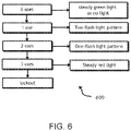
- the state diagram 600 shows example visual states that are displayed in response to a number of uses of a restroom appliance.
- the diagram 600 in FIG. 6 assumes that the maximum number of uses within the time period is three. It will be appreciated that various other maximum values may be used and that any number of different visual states may also be used.
- the visual state e.g., a first visual state
- the visual state may be a steady green light.
- the visual state e.g., a second visual state
- the visual state (e.g., a third visual state) may be a one-flash light pattern in which a red or green light flashes once between pauses to indicate that one use remains.
- the valve enters a lockout status and the visual state (e.g., a fourth visual state) may be a steady red light, a rapidly flashing light, or no light at all.
Landscapes
- Health & Medical Sciences (AREA)
- Engineering & Computer Science (AREA)
- Life Sciences & Earth Sciences (AREA)
- Public Health (AREA)
- Cardiology (AREA)
- Veterinary Medicine (AREA)
- General Health & Medical Sciences (AREA)
- Animal Behavior & Ethology (AREA)
- Biomedical Technology (AREA)
- Heart & Thoracic Surgery (AREA)
- Hydrology & Water Resources (AREA)
- Water Supply & Treatment (AREA)
- Aviation & Aerospace Engineering (AREA)
- Mechanical Engineering (AREA)
- Physics & Mathematics (AREA)
- Nuclear Medicine, Radiotherapy & Molecular Imaging (AREA)
- Radiology & Medical Imaging (AREA)
- Signal Processing (AREA)
- Molecular Biology (AREA)
- Pathology (AREA)
- Surgery (AREA)
- Medical Informatics (AREA)
- Biophysics (AREA)
- General Engineering & Computer Science (AREA)
- General Physics & Mathematics (AREA)
- Emergency Management (AREA)
- Business, Economics & Management (AREA)
- Computer Vision & Pattern Recognition (AREA)
- Psychiatry (AREA)
- Physiology (AREA)
- Artificial Intelligence (AREA)
- Human Computer Interaction (AREA)
- Domestic Plumbing Installations (AREA)
- Sanitary Device For Flush Toilet (AREA)
- Indication Of The Valve Opening Or Closing Status (AREA)
- Electromagnetism (AREA)
- Control Of Position, Course, Altitude, Or Attitude Of Moving Bodies (AREA)
Claims (17)
- Steuerungsvorrichtung (124, 126, 128, 130, 132) zur Verhinderung einer wiederholten Verwendung einer Toilettenvorrichtung (117, 119, 121, 132) durch einen Benutzer, wobei die Toilettenvorrichtung ein Ventil (116, 118, 120, 122), zumindest eine Anzeigevorrichtung (205, 301) und einen Aktuator (203, 201) umfasst,
der ausgelegt ist, eine Betätigung des Ventils zu bewirken, wobei die Steuerungsvorrichtung zumindest eine Steuerung (124, 126, 128, 130, 132) umfasst, die ausgelegt ist, um mit dem Ventil zu kommunizieren, wobei die zumindest eine Anzeigevorrichtung, der Aktuator und die zumindest eine Steuerung ausgelegt sind, um:die zumindest eine Anzeigevorrichtung zu steuern, um dem Benutzer der Toilettenvorrichtung einen ersten visuellen Zustand von zumindest drei unterschiedlichen visuellen Zuständen anzuzeigen;während einer ersten Zeitspanne eine Vielzahl von Anfragen zur Betätigung der Toilettenvorrichtung von dem Aktuator zu empfangen, wobei die Vielzahl von Anfragen eine maximale Anzahl an Ventilbetätigungen übersteigt, die der ersten Zeitspanne zugeordnet sind;eine erste Ventilbetätigung als Reaktion auf das Empfangen einer ersten Anfrage aus der Vielzahl von Anfragen durchzuführen;die zumindest eine Anzeigevorrichtung zu steuern, um dem Benutzer der Toilettenvorrichtung als Reaktion auf das Durchführen der ersten Ventilbetätigung oder das Empfangen der ersten Anfrage einen zweiten visuellen Zustand von den zumindest drei unterschiedlichen visuellen Zuständen anzuzeigen;zumindest eine nachfolgende Ventilbetätigung als Reaktion auf das Empfangen einer nachfolgenden Anfrage aus der Vielzahl von Anfragen durchzuführen, wobei die nachfolgende Anfrage der maximalen Anzahl an Ventilbetätigungen entspricht;die zumindest eine Anzeigevorrichtung zu steuern, um dem Benutzer der Toilettenvorrichtung als Reaktion auf das Durchführen der zumindest einen nachfolgenden Ventilbetätigung oder das Empfangen der zumindest einen nachfolgenden Anfrage einen dritten visuellen Zustand von den zumindest drei unterschiedlichen visuellen Zuständen anzuzeigen; undzusätzliche Ventilbetätigungen durch eine Anfrage des Aktuators während der ersten Zeitspanne und/oder für eine zweite Zeitspanne als Reaktion auf das Durchführen der zumindest einen nachfolgenden Ventilbetätigung oder das Empfangen der zumindest einen nachfolgenden Anfrage zu verhindern. - System (1000) zur Verhinderung der wiederholten Verwendung einer Toilettenvorrichtung (117, 119, 121, 123) mit visueller Rückmeldung, das Folgendes umfasst:ein Ventil (116, 118, 120, 122), das ausgelegt ist, um einen Fluidstrom zu der Toilettenvorrichtung durch zumindest eine Ventilbetätigung zu steuern;einen Aktuator (203, 201), der ausgelegt ist, um eine Verwendung der Toilettenvorrichtung anzufragen;zumindest eine Anzeigevorrichtung (205, 301), die ausgelegt ist, um zumindest drei unterschiedliche visuelle Zustände anzuzeigen; undeine Steuerungsvorrichtung (124, 126, 128, 130, 132) nach Anspruch 1.
- System nach Anspruch 2, wobei die zumindest eine Steuerung außerdem ausgelegt ist, um die zumindest eine Anzeigevorrichtung zu steuern, den ersten visuellen Zustand von den zumindest drei unterschiedlichen visuellen Zuständen als Reaktion auf das Bestimmen, dass die erste Zeitspanne und/oder die zweite Zeitspanne vergangen ist/sind, anzuzeigen.
- System nach Anspruch 2, wobei der Aktuator (201) einen Knopf (303) umfasst, der die zumindest eine Anzeigevorrichtung (301) umfasst, wobei die zumindest eine Anzeigevorrichtung ausgelegt ist, um Licht mit zumindest zwei unterschiedlichen Farben anzuzeigen.
- System nach Anspruch 2, wobei der Aktuator (201) einen Knopf (303) umfasst, der die zumindest eine Anzeigevorrichtung (301) umfasst, wobei die zumindest eine Anzeigevorrichtung als Ring, der den Knopf umgibt, angeordnet ist.
- System nach Anspruch 2, wobei der Aktuator zumindest eines aus Folgendem umfasst: einen Infrarotsensor, einen Annäherungssensor, einen Druckknopf, einen Kapazitätssensor, einen Hebel oder eine beliebige Kombination davon.
- System nach Anspruch 2, wobei der erste visuelle Zustand ein Dauerlicht ist, wobei der zweite visuelle Zustand ein Blinklicht ist, und wobei der dritte visuelle Zustand ein Dauer- oder Blinklicht mit einer anderen Farbe als jenes des ersten visuellen Zustands ist.
- System nach Anspruch 2, wobei die maximale Anzahl von Ventilbetätigungen drei ist.
- System nach Anspruch 2, wobei der zweite Zustand ein Lichtmuster umfasst, das eine Anzahl von Verwendungen, die durchgeführt wurden, oder eine Anzahl an Ventilbetätigungen, die innerhalb der ersten Zeitspanne übrig sind, anzeigt.
- System nach Anspruch 9, wobei das Lichtmuster das Blinken von Licht für eine bestimmte Anzahl an Malen, die der Anzahl an innerhalb der ersten Zeitspanne übrigen Ventilbetätigungen entsprechen, umfasst.
- System nach Anspruch 2, wobei zusätzliche Ventilbetätigungen auf Anfrage des Aktuators in einer zweiten Zeitspanne als Reaktion auf das Durchführen der zumindest einen nachfolgenden Ventilbetätigung oder das Empfangen der zumindest einen nachfolgenden Anfrage verhindert werden, wobei die zweite Zeitspanne eine Sperrzeit umfasst.
- System nach Anspruch 2, wobei zusätzliche Ventilbetätigungen auf Anfrage des Aktuators in einer verbleibenden Dauer der ersten Zeitspanne als Reaktion auf das Durchführen der zumindest einen nachfolgenden Ventilbetätigung oder das Empfangen der zumindest einen nachfolgenden Anfrage verhindert werden.
- System nach Anspruch 2, wobei die Ventilbetätigungen zumindest einen der folgenden umfassen: ein Spülen eines Spülventils, das Öffnen eines Absperrventils für eine vorbestimmte Zeitspanne oder das Öffnen eines Duschventils für eine vorbestimmte Zeitspanne.
- Verfahren zur Verhinderung der wiederholten Verwendung einer Toilettenvorrichtung mit visueller Rückmeldung, wobei die Toilettenvorrichtung ein Ventil, zumindest eine Anzeigevorrichtung und einen Aktuator umfasst, der ausgelegt ist, um eine Betätigung des Ventils zu bewirken, wobei das Verfahren Folgendes umfasst:das Steuern der zumindest einen Anzeigevorrichtung, um einem Benutzer der Toilettenvorrichtung einen ersten visuellen Zustand von zumindest drei unterschiedlichen visuellen Zuständen (403, 503) anzuzeigen;das Empfangen einer Vielzahl von Anfragen zur Betätigung der Toilettenvorrichtung von dem Aktuator während einer ersten Zeitspanne, wobei die Vielzahl von Anfragen eine maximale Anzahl an Ventilbetätigungen übersteigt, die mit der ersten Zeitspanne in Zusammenhang stehen;das Durchführen einer ersten Ventilbetätigung (407, 507) als Reaktion auf das Empfangen einer ersten Anfrage aus der Vielzahl von Anfragen (405, 505);das Steuern der zumindest einen Anzeigevorrichtung, um dem Benutzer der Toilettenvorrichtung als Reaktion auf das Durchführen der ersten Ventilbetätigung oder das Empfangen der ersten Anfrage einen zweiten visuellen Zustand von den zumindest drei unterschiedlichen visuellen Zuständen (419, 512, 519) anzuzeigen;das Durchführen der zumindest einen nachfolgenden Ventilbetätigung (418, 518) als Reaktion auf das Empfangen einer nachfolgenden Anfrage aus der Vielzahl von Anfragen, wobei die nachfolgende Anfrage der maximalen Anzahl an Ventilbetätigungen (413, 513) entspricht;das Steuern der zumindest einen Anzeigevorrichtung, um dem Benutzer der Toilettenvorrichtung als Reaktion auf das Durchführen der zumindest einen nachfolgenden Ventilbetätigung oder das Empfangen der zumindest einen nachfolgenden Anfrage einen dritten visuellen Zustand von den zumindest drei unterschiedlichen visuellen Zuständen (420, 522) anzuzeigen; unddas Verhindern von zusätzlichen Ventilbetätigungen (421, 523) durch eine Anfrage des Aktuators während des verbleibenden Teils der ersten Zeitspanne und/oder für eine zweite Zeitspanne als Reaktion auf das Durchführen der zumindest einen nachfolgenden Ventilbetätigung oder das Empfangen der zumindest einen nachfolgenden Anfrage.
- Verfahren nach Anspruch 14, das außerdem die Steuerung der zumindest einen Anzeigevorrichtung umfasst, um den ersten visuellen Zustand der zumindest drei unterschiedlichen visuellen Zustände als Reaktion auf die Bestimmung, dass die erste Zeitspanne und/oder die zweite Zeitspanne vergangen (415, 515) ist/sind, anzuzeigen.
- Verfahren nach Anspruch 14, wobei der Aktuator einen Knopf umfasst, der die zumindest eine Anzeigevorrichtung umfasst.
- Verfahren nach Anspruch 16, wobei die zumindest eine Anzeigevorrichtung als Ring, die den Knopf umgibt, angeordnet ist.
Priority Applications (1)
| Application Number | Priority Date | Filing Date | Title |
|---|---|---|---|
| HRP20220940TT HRP20220940T1 (hr) | 2016-09-08 | 2017-09-07 | Cjevovodni upravljački sustav, postupak i uređaj za sprečavanje ponovljene uporabe naprave s povratnom dojavom |
Applications Claiming Priority (2)
| Application Number | Priority Date | Filing Date | Title |
|---|---|---|---|
| US15/259,723 US9963863B2 (en) | 2016-09-08 | 2016-09-08 | Plumbing control system, method, and apparatus and preventing repeated use of an appliance with feedback |
| PCT/US2017/050410 WO2018048990A1 (en) | 2016-09-08 | 2017-09-07 | Plumbing control system, method, and apparatus for preventing repeated use of an appliance with feedback |
Publications (3)
| Publication Number | Publication Date |
|---|---|
| EP3494262A1 EP3494262A1 (de) | 2019-06-12 |
| EP3494262A4 EP3494262A4 (de) | 2020-04-15 |
| EP3494262B1 true EP3494262B1 (de) | 2022-06-29 |
Family
ID=61282158
Family Applications (1)
| Application Number | Title | Priority Date | Filing Date |
|---|---|---|---|
| EP17849506.5A Active EP3494262B1 (de) | 2016-09-08 | 2017-09-07 | Rohrleitungssteuerungssystem, -verfahren und -vorrichtung zur verhinderung einer wiederholten verwendung eines geräts mit rückmeldung |
Country Status (9)
| Country | Link |
|---|---|
| US (2) | US9963863B2 (de) |
| EP (1) | EP3494262B1 (de) |
| JP (1) | JP7002768B2 (de) |
| AU (2) | AU2017325011B2 (de) |
| CA (2) | CA3102802C (de) |
| ES (1) | ES2922255T3 (de) |
| HR (1) | HRP20220940T1 (de) |
| MX (1) | MX391008B (de) |
| WO (1) | WO2018048990A1 (de) |
Families Citing this family (13)
| Publication number | Priority date | Publication date | Assignee | Title |
|---|---|---|---|---|
| AU2019209965B2 (en) * | 2018-01-22 | 2024-12-19 | Hydraze, Inc. | Programmable toilet flush initiating, monitoring and management system and method thereof |
| US12270190B2 (en) | 2018-01-22 | 2025-04-08 | Hydraze, Inc. | Method and apparatus for controlling automatic toilet flushing system |
| US11866922B2 (en) | 2020-01-16 | 2024-01-09 | Hydraze, Inc. | Programmable toilet flush initiating, monitoring and management system and method thereof |
| US11739513B2 (en) | 2018-01-22 | 2023-08-29 | Hydraze, Inc. | Programmable toilet flush initiating, monitoring and management system and method thereof |
| US12301661B2 (en) | 2019-12-06 | 2025-05-13 | Zurn Water, Llc | Water management system and user interface |
| US11488457B2 (en) | 2020-06-08 | 2022-11-01 | Zurn Industries, Llc | Cloud-connected occupancy lights and status indication |
| US11108865B1 (en) | 2020-07-27 | 2021-08-31 | Zurn Industries, Llc | Battery powered end point device for IoT applications |
| US11153945B1 (en) | 2020-12-14 | 2021-10-19 | Zurn Industries, Llc | Facility occupancy detection with thermal grid sensor |
| US11594119B2 (en) | 2021-05-21 | 2023-02-28 | Zurn Industries, Llc | System and method for providing a connection status of a battery powered end point device |
| ES2848479R1 (es) * | 2021-06-22 | 2022-03-03 | Gil Orient Eric | Sistema de desagüe |
| US11543791B1 (en) | 2022-02-10 | 2023-01-03 | Zurn Industries, Llc | Determining operations for a smart fixture based on an area status |
| US11514679B1 (en) | 2022-02-18 | 2022-11-29 | Zurn Industries, Llc | Smart method for noise rejection in spatial human detection systems for a cloud connected occupancy sensing network |
| US11555734B1 (en) | 2022-02-18 | 2023-01-17 | Zurn Industries, Llc | Smart and cloud connected detection mechanism and real-time internet of things (IoT) system management |
Family Cites Families (14)
| Publication number | Priority date | Publication date | Assignee | Title |
|---|---|---|---|---|
| DE3262908D1 (en) | 1981-01-10 | 1985-05-15 | Laycock Bros Ltd | Flush control |
| US4985944A (en) | 1989-07-20 | 1991-01-22 | Bauer Industries Inc. | Plumbing control system and method for prisons |
| US5438714A (en) * | 1989-10-31 | 1995-08-08 | Bauer Industries, Inc. | Fresh water manifold distribution system and method |
| US5235706A (en) | 1991-09-06 | 1993-08-17 | Sloan Valve Company | Programmable urinal flushing delay circuit |
| EP1214479A1 (de) * | 1999-09-09 | 2002-06-19 | John Sykes | Toilette -oder urinalvorrichtung |
| US6477715B2 (en) | 2001-01-29 | 2002-11-12 | Ku Hyon Shin | Detachable disposable sweatband |
| US6477718B1 (en) * | 2001-07-31 | 2002-11-12 | Hsu Yun Wang | Toilet facility having image or video displayer |
| US6769443B2 (en) | 2002-04-29 | 2004-08-03 | I-Con Systems, Inc. | Plumbing control system with signal recognition |
| US8984675B2 (en) * | 2006-08-31 | 2015-03-24 | Thetford Corporation | Control system for a plurality of toilets and related method |
| MX2009003903A (es) | 2006-10-13 | 2009-06-11 | Sloan Valve Co | Fluxometro automatico programable. |
| JP5707733B2 (ja) | 2010-05-20 | 2015-04-30 | 株式会社Lixil | 便器洗浄装置 |
| JP5721047B2 (ja) | 2011-01-31 | 2015-05-20 | Toto株式会社 | 水栓装置 |
| US9728073B2 (en) | 2013-12-18 | 2017-08-08 | Sdb Ip Holdings, Llc | Plumbing control system with distress signal |
| SE538526C2 (sv) * | 2014-04-28 | 2016-09-06 | Villeroy & Boch Gustavsberg Ab | System och metod för övervakning av rörledningssystem |
-
2016
- 2016-09-08 US US15/259,723 patent/US9963863B2/en active Active
-
2017
- 2017-09-07 EP EP17849506.5A patent/EP3494262B1/de active Active
- 2017-09-07 CA CA3102802A patent/CA3102802C/en active Active
- 2017-09-07 HR HRP20220940TT patent/HRP20220940T1/hr unknown
- 2017-09-07 MX MX2019002757A patent/MX391008B/es unknown
- 2017-09-07 AU AU2017325011A patent/AU2017325011B2/en active Active
- 2017-09-07 JP JP2019513398A patent/JP7002768B2/ja active Active
- 2017-09-07 ES ES17849506T patent/ES2922255T3/es active Active
- 2017-09-07 WO PCT/US2017/050410 patent/WO2018048990A1/en not_active Ceased
- 2017-09-07 CA CA3035905A patent/CA3035905C/en active Active
-
2018
- 2018-04-13 US US15/952,552 patent/US10376706B2/en active Active
-
2020
- 2020-10-01 AU AU2020244537A patent/AU2020244537B2/en active Active
Also Published As
| Publication number | Publication date |
|---|---|
| CA3035905C (en) | 2021-02-16 |
| AU2017325011B2 (en) | 2020-07-02 |
| HRP20220940T1 (hr) | 2022-10-28 |
| MX2019002757A (es) | 2019-09-13 |
| MX391008B (es) | 2025-03-21 |
| CA3102802A1 (en) | 2018-03-15 |
| US20180066422A1 (en) | 2018-03-08 |
| EP3494262A4 (de) | 2020-04-15 |
| JP7002768B2 (ja) | 2022-01-20 |
| US10376706B2 (en) | 2019-08-13 |
| US20180236253A1 (en) | 2018-08-23 |
| EP3494262A1 (de) | 2019-06-12 |
| ES2922255T3 (es) | 2022-09-12 |
| CA3035905A1 (en) | 2018-03-15 |
| JP2019532198A (ja) | 2019-11-07 |
| AU2020244537B2 (en) | 2022-08-18 |
| WO2018048990A1 (en) | 2018-03-15 |
| AU2020244537A1 (en) | 2020-10-29 |
| CA3102802C (en) | 2021-11-30 |
| AU2017325011A1 (en) | 2019-03-28 |
| US9963863B2 (en) | 2018-05-08 |
Similar Documents
| Publication | Publication Date | Title |
|---|---|---|
| EP3494262B1 (de) | Rohrleitungssteuerungssystem, -verfahren und -vorrichtung zur verhinderung einer wiederholten verwendung eines geräts mit rückmeldung | |
| US5095945A (en) | Electronic tapware | |
| US6769443B2 (en) | Plumbing control system with signal recognition | |
| ES2820748T3 (es) | Sistema de control de tuberías con señal de socorro | |
| US6956498B1 (en) | System for remote operation of a personal hygiene or sanitary appliance | |
| JP4451482B2 (ja) | 給湯装置 | |
| EP3232882B1 (de) | System mit einem behälter und einem steuersystem, um unbedingtes spülen zu vermeiden | |
| KR19990067442A (ko) | 무선 온도 감지 시스템 | |
| GB2340964A (en) | Controlling water supply valves | |
| CN1270036C (zh) | 一种用于个人卫生或清洁器具的远程操作系统 | |
| US9637901B2 (en) | Method for setting parameters | |
| EP3011404B1 (de) | Abnehmbare zeiteinstellungsvorrichtung, system und verfahren zum einstellen einer elektronischen sanitärsteuerung | |
| JP6966880B2 (ja) | 自動水栓のモード切替操作装置 | |
| EP3064664A1 (de) | Automatisches system und verfahren zum spülen eines sanitärbeckens | |
| JP2019007183A (ja) | 自動水栓の制御装置 | |
| JP2778793B2 (ja) | シャワー装置 | |
| JP2773843B2 (ja) | シャワー装置 | |
| JP2000295680A (ja) | リモコン装置の表示制御方法 | |
| AU621875B2 (en) | Electronic tapware | |
| JPH09217399A (ja) | 給水制御装置 |
Legal Events
| Date | Code | Title | Description |
|---|---|---|---|
| REG | Reference to a national code |
Ref country code: HR Ref legal event code: TUEP Ref document number: P20220940 Country of ref document: HR |
|
| STAA | Information on the status of an ep patent application or granted ep patent |
Free format text: STATUS: THE INTERNATIONAL PUBLICATION HAS BEEN MADE |
|
| PUAI | Public reference made under article 153(3) epc to a published international application that has entered the european phase |
Free format text: ORIGINAL CODE: 0009012 |
|
| STAA | Information on the status of an ep patent application or granted ep patent |
Free format text: STATUS: REQUEST FOR EXAMINATION WAS MADE |
|
| 17P | Request for examination filed |
Effective date: 20190228 |
|
| AK | Designated contracting states |
Kind code of ref document: A1 Designated state(s): AL AT BE BG CH CY CZ DE DK EE ES FI FR GB GR HR HU IE IS IT LI LT LU LV MC MK MT NL NO PL PT RO RS SE SI SK SM TR |
|
| AX | Request for extension of the european patent |
Extension state: BA ME |
|
| DAV | Request for validation of the european patent (deleted) | ||
| DAX | Request for extension of the european patent (deleted) | ||
| A4 | Supplementary search report drawn up and despatched |
Effective date: 20200313 |
|
| RIC1 | Information provided on ipc code assigned before grant |
Ipc: E03D 5/09 20060101ALI20200309BHEP Ipc: E03D 5/02 20060101ALI20200309BHEP Ipc: E03D 5/10 20060101AFI20200309BHEP |
|
| GRAP | Despatch of communication of intention to grant a patent |
Free format text: ORIGINAL CODE: EPIDOSNIGR1 |
|
| STAA | Information on the status of an ep patent application or granted ep patent |
Free format text: STATUS: GRANT OF PATENT IS INTENDED |
|
| RIC1 | Information provided on ipc code assigned before grant |
Ipc: G08B 5/36 20060101ALN20211217BHEP Ipc: E03D 5/09 20060101ALI20211217BHEP Ipc: E03D 5/02 20060101ALI20211217BHEP Ipc: E03D 5/10 20060101AFI20211217BHEP |
|
| RIC1 | Information provided on ipc code assigned before grant |
Ipc: G08B 5/36 20060101ALN20220103BHEP Ipc: E03D 5/09 20060101ALI20220103BHEP Ipc: E03D 5/02 20060101ALI20220103BHEP Ipc: E03D 5/10 20060101AFI20220103BHEP |
|
| INTG | Intention to grant announced |
Effective date: 20220120 |
|
| RIC1 | Information provided on ipc code assigned before grant |
Ipc: G08B 5/36 20060101ALN20220111BHEP Ipc: E03D 5/09 20060101ALI20220111BHEP Ipc: E03D 5/02 20060101ALI20220111BHEP Ipc: E03D 5/10 20060101AFI20220111BHEP |
|
| GRAS | Grant fee paid |
Free format text: ORIGINAL CODE: EPIDOSNIGR3 |
|
| GRAA | (expected) grant |
Free format text: ORIGINAL CODE: 0009210 |
|
| STAA | Information on the status of an ep patent application or granted ep patent |
Free format text: STATUS: THE PATENT HAS BEEN GRANTED |
|
| AK | Designated contracting states |
Kind code of ref document: B1 Designated state(s): AL AT BE BG CH CY CZ DE DK EE ES FI FR GB GR HR HU IE IS IT LI LT LU LV MC MK MT NL NO PL PT RO RS SE SI SK SM TR |
|
| REG | Reference to a national code |
Ref country code: CH Ref legal event code: EP |
|
| REG | Reference to a national code |
Ref country code: AT Ref legal event code: REF Ref document number: 1501444 Country of ref document: AT Kind code of ref document: T Effective date: 20220715 |
|
| REG | Reference to a national code |
Ref country code: IE Ref legal event code: FG4D |
|
| REG | Reference to a national code |
Ref country code: DE Ref legal event code: R096 Ref document number: 602017059087 Country of ref document: DE |
|
| REG | Reference to a national code |
Ref country code: ES Ref legal event code: FG2A Ref document number: 2922255 Country of ref document: ES Kind code of ref document: T3 Effective date: 20220912 |
|
| REG | Reference to a national code |
Ref country code: LT Ref legal event code: MG9D |
|
| REG | Reference to a national code |
Ref country code: HR Ref legal event code: T1PR Ref document number: P20220940 Country of ref document: HR |
|
| PG25 | Lapsed in a contracting state [announced via postgrant information from national office to epo] |
Ref country code: SE Free format text: LAPSE BECAUSE OF FAILURE TO SUBMIT A TRANSLATION OF THE DESCRIPTION OR TO PAY THE FEE WITHIN THE PRESCRIBED TIME-LIMIT Effective date: 20220629 Ref country code: NO Free format text: LAPSE BECAUSE OF FAILURE TO SUBMIT A TRANSLATION OF THE DESCRIPTION OR TO PAY THE FEE WITHIN THE PRESCRIBED TIME-LIMIT Effective date: 20220929 Ref country code: LT Free format text: LAPSE BECAUSE OF FAILURE TO SUBMIT A TRANSLATION OF THE DESCRIPTION OR TO PAY THE FEE WITHIN THE PRESCRIBED TIME-LIMIT Effective date: 20220629 Ref country code: GR Free format text: LAPSE BECAUSE OF FAILURE TO SUBMIT A TRANSLATION OF THE DESCRIPTION OR TO PAY THE FEE WITHIN THE PRESCRIBED TIME-LIMIT Effective date: 20220930 Ref country code: FI Free format text: LAPSE BECAUSE OF FAILURE TO SUBMIT A TRANSLATION OF THE DESCRIPTION OR TO PAY THE FEE WITHIN THE PRESCRIBED TIME-LIMIT Effective date: 20220629 Ref country code: BG Free format text: LAPSE BECAUSE OF FAILURE TO SUBMIT A TRANSLATION OF THE DESCRIPTION OR TO PAY THE FEE WITHIN THE PRESCRIBED TIME-LIMIT Effective date: 20220929 |
|
| REG | Reference to a national code |
Ref country code: NL Ref legal event code: MP Effective date: 20220629 |
|
| REG | Reference to a national code |
Ref country code: AT Ref legal event code: MK05 Ref document number: 1501444 Country of ref document: AT Kind code of ref document: T Effective date: 20220629 |
|
| REG | Reference to a national code |
Ref country code: HR Ref legal event code: ODRP Ref document number: P20220940 Country of ref document: HR Payment date: 20220906 Year of fee payment: 6 |
|
| PG25 | Lapsed in a contracting state [announced via postgrant information from national office to epo] |
Ref country code: RS Free format text: LAPSE BECAUSE OF FAILURE TO SUBMIT A TRANSLATION OF THE DESCRIPTION OR TO PAY THE FEE WITHIN THE PRESCRIBED TIME-LIMIT Effective date: 20220629 Ref country code: LV Free format text: LAPSE BECAUSE OF FAILURE TO SUBMIT A TRANSLATION OF THE DESCRIPTION OR TO PAY THE FEE WITHIN THE PRESCRIBED TIME-LIMIT Effective date: 20220629 |
|
| PG25 | Lapsed in a contracting state [announced via postgrant information from national office to epo] |
Ref country code: NL Free format text: LAPSE BECAUSE OF FAILURE TO SUBMIT A TRANSLATION OF THE DESCRIPTION OR TO PAY THE FEE WITHIN THE PRESCRIBED TIME-LIMIT Effective date: 20220629 |
|
| PG25 | Lapsed in a contracting state [announced via postgrant information from national office to epo] |
Ref country code: SM Free format text: LAPSE BECAUSE OF FAILURE TO SUBMIT A TRANSLATION OF THE DESCRIPTION OR TO PAY THE FEE WITHIN THE PRESCRIBED TIME-LIMIT Effective date: 20220629 Ref country code: SK Free format text: LAPSE BECAUSE OF FAILURE TO SUBMIT A TRANSLATION OF THE DESCRIPTION OR TO PAY THE FEE WITHIN THE PRESCRIBED TIME-LIMIT Effective date: 20220629 Ref country code: RO Free format text: LAPSE BECAUSE OF FAILURE TO SUBMIT A TRANSLATION OF THE DESCRIPTION OR TO PAY THE FEE WITHIN THE PRESCRIBED TIME-LIMIT Effective date: 20220629 Ref country code: PT Free format text: LAPSE BECAUSE OF FAILURE TO SUBMIT A TRANSLATION OF THE DESCRIPTION OR TO PAY THE FEE WITHIN THE PRESCRIBED TIME-LIMIT Effective date: 20221031 Ref country code: EE Free format text: LAPSE BECAUSE OF FAILURE TO SUBMIT A TRANSLATION OF THE DESCRIPTION OR TO PAY THE FEE WITHIN THE PRESCRIBED TIME-LIMIT Effective date: 20220629 Ref country code: AT Free format text: LAPSE BECAUSE OF FAILURE TO SUBMIT A TRANSLATION OF THE DESCRIPTION OR TO PAY THE FEE WITHIN THE PRESCRIBED TIME-LIMIT Effective date: 20220629 |
|
| PG25 | Lapsed in a contracting state [announced via postgrant information from national office to epo] |
Ref country code: PL Free format text: LAPSE BECAUSE OF FAILURE TO SUBMIT A TRANSLATION OF THE DESCRIPTION OR TO PAY THE FEE WITHIN THE PRESCRIBED TIME-LIMIT Effective date: 20220629 Ref country code: IS Free format text: LAPSE BECAUSE OF FAILURE TO SUBMIT A TRANSLATION OF THE DESCRIPTION OR TO PAY THE FEE WITHIN THE PRESCRIBED TIME-LIMIT Effective date: 20221029 |
|
| REG | Reference to a national code |
Ref country code: DE Ref legal event code: R097 Ref document number: 602017059087 Country of ref document: DE |
|
| PG25 | Lapsed in a contracting state [announced via postgrant information from national office to epo] |
Ref country code: AL Free format text: LAPSE BECAUSE OF FAILURE TO SUBMIT A TRANSLATION OF THE DESCRIPTION OR TO PAY THE FEE WITHIN THE PRESCRIBED TIME-LIMIT Effective date: 20220629 |
|
| PG25 | Lapsed in a contracting state [announced via postgrant information from national office to epo] |
Ref country code: MC Free format text: LAPSE BECAUSE OF FAILURE TO SUBMIT A TRANSLATION OF THE DESCRIPTION OR TO PAY THE FEE WITHIN THE PRESCRIBED TIME-LIMIT Effective date: 20220629 Ref country code: DK Free format text: LAPSE BECAUSE OF FAILURE TO SUBMIT A TRANSLATION OF THE DESCRIPTION OR TO PAY THE FEE WITHIN THE PRESCRIBED TIME-LIMIT Effective date: 20220629 Ref country code: CZ Free format text: LAPSE BECAUSE OF FAILURE TO SUBMIT A TRANSLATION OF THE DESCRIPTION OR TO PAY THE FEE WITHIN THE PRESCRIBED TIME-LIMIT Effective date: 20220629 |
|
| REG | Reference to a national code |
Ref country code: CH Ref legal event code: PL |
|
| PLBE | No opposition filed within time limit |
Free format text: ORIGINAL CODE: 0009261 |
|
| STAA | Information on the status of an ep patent application or granted ep patent |
Free format text: STATUS: NO OPPOSITION FILED WITHIN TIME LIMIT |
|
| REG | Reference to a national code |
Ref country code: BE Ref legal event code: MM Effective date: 20220930 |
|
| 26N | No opposition filed |
Effective date: 20230330 |
|
| PG25 | Lapsed in a contracting state [announced via postgrant information from national office to epo] |
Ref country code: LU Free format text: LAPSE BECAUSE OF NON-PAYMENT OF DUE FEES Effective date: 20220907 |
|
| PG25 | Lapsed in a contracting state [announced via postgrant information from national office to epo] |
Ref country code: LI Free format text: LAPSE BECAUSE OF NON-PAYMENT OF DUE FEES Effective date: 20220930 Ref country code: IE Free format text: LAPSE BECAUSE OF NON-PAYMENT OF DUE FEES Effective date: 20220907 Ref country code: CH Free format text: LAPSE BECAUSE OF NON-PAYMENT OF DUE FEES Effective date: 20220930 |
|
| PG25 | Lapsed in a contracting state [announced via postgrant information from national office to epo] |
Ref country code: SI Free format text: LAPSE BECAUSE OF FAILURE TO SUBMIT A TRANSLATION OF THE DESCRIPTION OR TO PAY THE FEE WITHIN THE PRESCRIBED TIME-LIMIT Effective date: 20220629 |
|
| REG | Reference to a national code |
Ref country code: HR Ref legal event code: ODRP Ref document number: P20220940 Country of ref document: HR Payment date: 20230731 Year of fee payment: 7 |
|
| PG25 | Lapsed in a contracting state [announced via postgrant information from national office to epo] |
Ref country code: BE Free format text: LAPSE BECAUSE OF NON-PAYMENT OF DUE FEES Effective date: 20220930 |
|
| PG25 | Lapsed in a contracting state [announced via postgrant information from national office to epo] |
Ref country code: HU Free format text: LAPSE BECAUSE OF FAILURE TO SUBMIT A TRANSLATION OF THE DESCRIPTION OR TO PAY THE FEE WITHIN THE PRESCRIBED TIME-LIMIT; INVALID AB INITIO Effective date: 20170907 |
|
| PG25 | Lapsed in a contracting state [announced via postgrant information from national office to epo] |
Ref country code: CY Free format text: LAPSE BECAUSE OF FAILURE TO SUBMIT A TRANSLATION OF THE DESCRIPTION OR TO PAY THE FEE WITHIN THE PRESCRIBED TIME-LIMIT Effective date: 20220629 |
|
| PG25 | Lapsed in a contracting state [announced via postgrant information from national office to epo] |
Ref country code: MK Free format text: LAPSE BECAUSE OF FAILURE TO SUBMIT A TRANSLATION OF THE DESCRIPTION OR TO PAY THE FEE WITHIN THE PRESCRIBED TIME-LIMIT Effective date: 20220629 |
|
| REG | Reference to a national code |
Ref country code: HR Ref legal event code: ODRP Ref document number: P20220940 Country of ref document: HR Payment date: 20240726 Year of fee payment: 8 |
|
| PG25 | Lapsed in a contracting state [announced via postgrant information from national office to epo] |
Ref country code: MT Free format text: LAPSE BECAUSE OF FAILURE TO SUBMIT A TRANSLATION OF THE DESCRIPTION OR TO PAY THE FEE WITHIN THE PRESCRIBED TIME-LIMIT Effective date: 20220629 |
|
| PG25 | Lapsed in a contracting state [announced via postgrant information from national office to epo] |
Ref country code: BG Free format text: LAPSE BECAUSE OF FAILURE TO SUBMIT A TRANSLATION OF THE DESCRIPTION OR TO PAY THE FEE WITHIN THE PRESCRIBED TIME-LIMIT Effective date: 20220629 |
|
| PG25 | Lapsed in a contracting state [announced via postgrant information from national office to epo] |
Ref country code: BG Free format text: LAPSE BECAUSE OF FAILURE TO SUBMIT A TRANSLATION OF THE DESCRIPTION OR TO PAY THE FEE WITHIN THE PRESCRIBED TIME-LIMIT Effective date: 20220629 |
|
| REG | Reference to a national code |
Ref country code: HR Ref legal event code: ODRP Ref document number: P20220940 Country of ref document: HR Payment date: 20250903 Year of fee payment: 9 |
|
| PGFP | Annual fee paid to national office [announced via postgrant information from national office to epo] |
Ref country code: DE Payment date: 20250929 Year of fee payment: 9 |
|
| PGFP | Annual fee paid to national office [announced via postgrant information from national office to epo] |
Ref country code: IT Payment date: 20250919 Year of fee payment: 9 |
|
| PGFP | Annual fee paid to national office [announced via postgrant information from national office to epo] |
Ref country code: GB Payment date: 20250929 Year of fee payment: 9 |
|
| PGFP | Annual fee paid to national office [announced via postgrant information from national office to epo] |
Ref country code: HR Payment date: 20250903 Year of fee payment: 9 |
|
| PGFP | Annual fee paid to national office [announced via postgrant information from national office to epo] |
Ref country code: FR Payment date: 20250925 Year of fee payment: 9 |
|
| PG25 | Lapsed in a contracting state [announced via postgrant information from national office to epo] |
Ref country code: TR Free format text: LAPSE BECAUSE OF FAILURE TO SUBMIT A TRANSLATION OF THE DESCRIPTION OR TO PAY THE FEE WITHIN THE PRESCRIBED TIME-LIMIT Effective date: 20220629 |
|
| PGFP | Annual fee paid to national office [announced via postgrant information from national office to epo] |
Ref country code: ES Payment date: 20251001 Year of fee payment: 9 |