EP3495584A1 - Gerüst für bauelement, bauelement, das ein solches gerüst umfasst, und entsprechendes herstellungsverfahren - Google Patents
Gerüst für bauelement, bauelement, das ein solches gerüst umfasst, und entsprechendes herstellungsverfahren Download PDFInfo
- Publication number
- EP3495584A1 EP3495584A1 EP18211777.0A EP18211777A EP3495584A1 EP 3495584 A1 EP3495584 A1 EP 3495584A1 EP 18211777 A EP18211777 A EP 18211777A EP 3495584 A1 EP3495584 A1 EP 3495584A1
- Authority
- EP
- European Patent Office
- Prior art keywords
- skeleton
- cells
- construction element
- longitudinal axis
- axis
- Prior art date
- Legal status (The legal status is an assumption and is not a legal conclusion. Google has not performed a legal analysis and makes no representation as to the accuracy of the status listed.)
- Granted
Links
Images




Classifications
-
- E—FIXED CONSTRUCTIONS
- E04—BUILDING
- E04G—SCAFFOLDING; FORMS; SHUTTERING; BUILDING IMPLEMENTS OR AIDS, OR THEIR USE; HANDLING BUILDING MATERIALS ON THE SITE; REPAIRING, BREAKING-UP OR OTHER WORK ON EXISTING BUILDINGS
- E04G9/00—Forming or shuttering elements for general use
- E04G9/08—Forming boards or similar elements, which are collapsible, foldable, or able to be rolled up
-
- E—FIXED CONSTRUCTIONS
- E01—CONSTRUCTION OF ROADS, RAILWAYS, OR BRIDGES
- E01C—CONSTRUCTION OF, OR SURFACES FOR, ROADS, SPORTS GROUNDS, OR THE LIKE; MACHINES OR AUXILIARY TOOLS FOR CONSTRUCTION OR REPAIR
- E01C11/00—Details of pavings
- E01C11/02—Arrangement or construction of joints; Methods of making joints; Packing for joints
- E01C11/04—Arrangement or construction of joints; Methods of making joints; Packing for joints for cement concrete paving
- E01C11/10—Packing of plastic or elastic materials, e.g. wood, resin
-
- E—FIXED CONSTRUCTIONS
- E01—CONSTRUCTION OF ROADS, RAILWAYS, OR BRIDGES
- E01D—CONSTRUCTION OF BRIDGES, ELEVATED ROADWAYS OR VIADUCTS; ASSEMBLY OF BRIDGES
- E01D19/00—Structural or constructional details of bridges
- E01D19/06—Arrangement, construction or bridging of expansion joints
-
- E—FIXED CONSTRUCTIONS
- E01—CONSTRUCTION OF ROADS, RAILWAYS, OR BRIDGES
- E01D—CONSTRUCTION OF BRIDGES, ELEVATED ROADWAYS OR VIADUCTS; ASSEMBLY OF BRIDGES
- E01D19/00—Structural or constructional details of bridges
- E01D19/06—Arrangement, construction or bridging of expansion joints
- E01D19/067—Flat continuous joints cast in situ
-
- E—FIXED CONSTRUCTIONS
- E04—BUILDING
- E04G—SCAFFOLDING; FORMS; SHUTTERING; BUILDING IMPLEMENTS OR AIDS, OR THEIR USE; HANDLING BUILDING MATERIALS ON THE SITE; REPAIRING, BREAKING-UP OR OTHER WORK ON EXISTING BUILDINGS
- E04G9/00—Forming or shuttering elements for general use
- E04G9/02—Forming boards or similar elements
- E04G9/021—Forming boards or similar elements the form surface being of cardboard
Definitions
- the invention relates to a skeleton for a construction element.
- the invention also relates to a construction element comprising such a skeleton.
- the construction element is for example a structure (bridge, tunnel, dock, dike ...) or a roadway or a portion of roadway or a road joint and / or engineering structure.
- the invention also relates to a method of producing an associated building element.
- Structures are constructions of important dimensions such as bridges, tunnels, wharves, dikes ... presenting by their dimensions cuts at the junction between the various elements constituting them.
- joints In order to fill these junctions and thus ensure a continuity of the outer coating of the structure considered due to the expansion of the various materials used, it is known to arrange joints at said junctions.
- the normal-coated apparent joints comprise a sheet arranged at the seal void so as to form a reservoir, which tank is filled with a sealant.
- a standard bitumen then covers the whole.
- Also known are improved coated seals comprising a bridging plate arranged to cover the joint gap, said plate being covered with a special coating generally consisting of a mixture of binder and granules.
- Such apparent improved-coated joints have a blast capacity which is larger than the normal-coated exposed joints (being recalled that a "breath" of a joint corresponds to the variation of dimensions that the joint can take relative to its initial position at the moment of its installation for example when the joint is dilated, from the breath one can thus estimate the relative displacement maximum allowed between two elements that the joint connects so that the seal can fulfill its function of continuity between said two elements).
- An object of the invention is to provide a solution for a building element to have better properties especially in terms of wear resistance.
- a skeleton for a construction element comprising a honeycomb structure extending longitudinally along a longitudinal axis, said structure comprising polygonal section cells having for normal an orthogonal axis to the longitudinal axis.
- the cells allow the skeleton to be able to more easily accompany the deformation of the building element due for example to the expansion of the constituent materials.
- the invention makes it easier to support deformations of a construction element in which the skeleton is arranged.
- the skeleton, and thus the associated construction element has a relatively high rigidity along the axis orthogonal to the longitudinal axis due to the particular arrangement of the cells.
- This makes it possible to have a construction element which is more resistant, for example to the passage of vehicles traveling on said building element. This also limits creep and rutting of said element.
- the invention therefore makes it possible to have a building element having good properties, especially mechanical properties.
- At least two cells have sections of different shapes.
- the structure is rubber.
- the structure comprises at least two rows of cells.
- At least one cell has a hexagonal section.
- the cell has an irregular hexagonal section.
- the cell has a flattened hexagon section.
- At least two cells are separated by another cell of different shape from those of said two cells.
- the structure comprises at least one arm extending parallel to the longitudinal axis of said structure.
- the skeleton comprises at least one reinforcing element of the structure.
- the invention also relates to a construction element comprising a skeleton as mentioned above.
- the skeleton ensures in particular a better homogeneity of the coating of the building element in time and seasons.
- the filling material comprises aggregates coated with bitumen.
- a skeleton according to a particular embodiment of the invention will now be described.
- the skeleton is used here in a joint of a structure of art such as a bridge, a tunnel, a quay, a dike ...
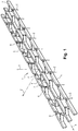
- the skeleton generally designated 1, comprises a honeycomb structure 2.
- the structure 2 is in an elastically deformable material.
- said structure 2 is made of natural rubber or synthetic rubber.
- Said structure 2 is for example vulcanized rubber.
- the structure 2 extends longitudinally along a longitudinal axis X.
- Said structure 2 comprises cavities 3 (only one of which is referenced here) of section having for normal a second axis Y perpendicular to the longitudinal axis X.
- the structure 2 comprises at least two rows of cells 3, the rows being parallel to each other and to the longitudinal axis X. Each row thus comprises a succession, along the longitudinal axis X, of cells 3.
- the structure 2 comprises two rows of cells 3. According to a particular embodiment, the two rows are identical to each other. Typically, each row comprises a first type of cells 3 and a second type of cells 4.
- the first cells 3 are typically of polygonal sections (section having for normal the second axis Y).
- the first cells 3 are all identical to each other here between two different rows.
- the first cells 3 have for example a section (having for normal second axis Y) shaped irregular hexagon.
- the first cells 3 thus have two opposite faces of longer length than those of the other four faces. Said faces of greater length extend parallel to the longitudinal axis X. The other four faces are of identical length.
- the first cells 3 are thus substantially shaped into flattened hexagonal prisms along a third axis Z, perpendicular to the longitudinal axis X and the second axis Y.
- the first cells 3 of the same row are not contiguous.
- the first cells 3 of the same row are thus separated from each other by the same distance (along the longitudinal axis X).
- the structure 2 thus has between two cells 3 of the same row, a cell 4 of the second type (only one of which is referenced here) which is here substantially hourglass-shaped.
- the different second cells 4 are all identical to each other here between two different rows.
- each first cell 3 of the first row is aligned (along the third axis Z) with a first cell 3 of the respective second row, and correspondingly each second cell 4 of the first row is aligned ( along the third axis Z) with a second respective cell 4 of the second row.
- the first cells 3 and / or the second cells 4 of the ends of the skeleton 1 may be whole or cut.
- the rows of the first cells 3 are bordered externally by a first longitudinal arm 5 and a second longitudinal arm 6 of the structure 2, the first arm 5 and the second arm 6 both extending parallel to the longitudinal axis X.
- the structure 2 also comprises a central longitudinal arm 7 separating the two rows of cells.
- Said central arm 7 is here parallel to the two arms 5, 6 and extends along the longitudinal axis X.
- the different arms form faces of the cells 3, 4 (in this case the two faces of the first cells 3 of the largest length).
- the central arm 7 and the two arms 5, 6 constitute the thickest parts of the structure 2.
- the rest of the structure 2 has the same thickness less than that of the arms 5, 6, 7.
- Said thickness of the rest of the structure 2 is between 20 and 100 millimeters and preferably between 50 and 70 millimeters.
- said thickness is substantially 60 millimeters.
- the thickness of the arms 5, 6, 7 is here at least greater than 60 millimeters.
- the skeleton 1 comprises at least one reinforcing element of the structure 2.
- the reinforcing element or elements extend parallel to the longitudinal axis X.
- the reinforcing element or elements are made of metal and for example steel.
- the skeleton 1 comprises one or more reinforcement elements entirely embedded in the structure 2.
- each reinforcing element is shaped as a bar arranged inside the structure 2.
- the skeleton 1 comprises a first bar extending in the first arm 5, a second bar extending in the second arm 6 and a central bar extending in the central arm 7 (the various bars are here not visible because embedded in the arms of the structure 2).
- the reinforcement elements are inserted into the thickest parts of the structure 2.
- the skeleton 1 comprises openings in the structure 2 for the passage of means for fixing the skeleton 1 as we shall see later.
- Said openings are in the form of an orifice and / or a recess.
- the skeleton 1 comprises here only recesses 8 formed in the first arm 5 and the second arm 6 at regular intervals (or not) so that the recesses 8 of the first arm 5 are aligned respectively with one of the recesses of the second arm 6.
- the skeleton 1 comprises a recess 8 substantially at the center of a face of each cell 3, 4 formed by the arm.
- Each recess 8 thus forms a housing in the associated arm.
- the housings 8 here have a substantially parallelepiped shape.
- the means for fixing the skeleton 1 are arranged at the level of the arms 5, 6 of the structure 2, or at the level of the thickest parts of the structure.
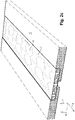
- said work of art 10 is hollowed over the joint gap to form a reservation 11.
- the skeleton 1 is then placed in said reservation 11 above the seal gap.
- the skeleton 1 does not rely here directly on the joint gap but on a layer of bitumen, concrete, binder ... or any other material such as for example a bridging plate made of metallic material itself. plumb of joint vacuum.
- the skeleton 1 thus extends transversely to the structure 10.
- the third axis Z of the skeleton 1 corresponds to the longitudinal direction of the structure 10.
- the rigidity of the seal 12 along the second axis Y allows the seal 12 to be more resistant to the passage of vehicles traveling on the structure 10. This also limits creep and rutting of the seal 12 .
- the skeleton 1 extends substantially in a horizontal plane and the second axis Y extends substantially vertically.
- skeleton 1 is then secured to the reservation 11 by fastening means such as for example using piles sometimes called sticks C.
- Said sticks C typically comprise a rod (threaded or not) extended by a hook: the rods are driven into the structure 10 beyond the reservation (typically in holes made for this purpose) and the hooks are s press the skeleton 1 recesses so as to press the skeleton 1 against the bottom of the reservation. Each hook thus surrounds the associated arm of the skeleton 1. It is possible to seal the stems of the butts C at the reservation for example by hydraulic mortar or by chemical sealing.
- the distance separating two sticks C (along the first axis X) can vary along the skeleton 1.
- the filling material 13 is for example composed of aggregates, and preferably aggregates coated with bitumen, such as in particular, although not exclusively, modified bitumen. by a polymer (such as an elastomer).
- a hydrocarbon binder 14 is poured over the above aggregates, and preferably a bituminous binder (modified or not by a polymer such as an elastomer).
- a finishing layer 15 is created on said special coating block to ensure the most complete continuity possible between the various elements of the structure 10 which the seal 12 connects.
- This topcoat 15 is for example created from a hydrocarbon binder sprinkled with micro-granulates.
- the seal 12 has thus been created simply and quickly.
- the skeleton 1 used is easily adaptable to joints 12 already existing and should be renovated. Indeed, it is sufficient on site to cut the skeleton 1 to the right length (along the longitudinal axis X) and dig the reservation 11 to the right depth (along the second axis Y) to arrange the skeleton 1 in any type of booking. In the same way, such a skeleton 1 can be used in half-pavements and without discontinuity between the two semi-shores considered.
- skeleton 1 used is also quite suitable for new structures.
- the seal 12 has for example a breath that can go beyond 60 millimeters.
- the skeleton can be associated with other types of joint such as a normal coated joint or an improved coated joint.
- the joint may have a different wind than what has been indicated.
- the skeleton may be associated with joints requiring highly variable blasts.
- the skeleton may well be associated with joints requiring a blast equal to zero that joints requiring a larger breath, the skeleton can be associated with joints requiring breaths greater than 60 millimeters.
- the skeleton can be used for other building elements that a work of art such as a roadway.
- the method of implementation of the skeleton will for example be identical to that described above for a seal.
- the thickness of the structure 2 may be different from what has been indicated (whether the structure has a uniform thickness or not).
- the thickness of the structure 2 may thus be between 10 and 100 millimeters and for example between 30 and 60 millimeters.
- the honeycomb structure may take another form than that indicated and for example have a different number of rows of cells and / or a different shape of cells.
- the honeycomb structure may for example comprise a single row.
- the cells may be contiguous within the same row and / or be shifted from one row to another. Within the same structure, it will be possible to have cells of different shape and / or size.
- the structure may for example be in the form of honeycombs.
- One or more cells may have a section in the form of pentagon, regular hexagon ...
- the honeycomb structure may not have arms.
- skeleton of the type of that of the figure 1 but whose angles of the cells 3, 4 have been rounded.
- the skeleton further comprises three rows of cells, the rows being separated in pairs by a central arm 7.
- the cavities 3 all have the same shape, namely a chevron shape delimited, along the length of the row, by two V-shaped parts connecting the arm 6 to the arm 7.
- the cells 3 of a row here all extend in the same direction, this sense being opposite to that of the cells 3 of the adjacent row.
- the cells 3 of a row are furthermore positioned relative to the cells 3 of the adjacent row in such a way that the parts in V separating two by two the cells 3 of a row extend in the extension of the V parts separating in pairs the cells 3 of the adjacent row.
- the cells 3 of a row are offset relative to the cells 3 of the adjacent row and / or that the cells 3 of two adjacent rows extend in the same direction.
- the arm 7 has a rectilinear shape here, but it could have a zig-zag or wavy shape.
- the skeleton may not have a reinforcing element.
- the skeleton may not have a metal reinforcing element.
- the skeleton may not be secured to the reservation.
- the skeleton may not be secured to the reservation including, although not exclusively, when the blast of the seal may be less than or equal to substantially 20 millimeters (which depends on the intended applications) .
- the skeleton can be secured to the reservation otherwise than by sticks such as with the help of rods passing through the skeleton or with the help of threaded rods.
- the skeleton is arranged on an existing structure or roadway
- the skeleton can be arranged on a structure or roadway under construction.
- the building element may comprise a single skeleton as described above or two or more skeletons that will be juxtaposed or not, in the direction of the width or length or height of the building element.
Landscapes
- Engineering & Computer Science (AREA)
- Architecture (AREA)
- Civil Engineering (AREA)
- Structural Engineering (AREA)
- Mechanical Engineering (AREA)
- Road Paving Structures (AREA)
- Rod-Shaped Construction Members (AREA)
- Bridges Or Land Bridges (AREA)
Applications Claiming Priority (1)
| Application Number | Priority Date | Filing Date | Title |
|---|---|---|---|
| FR1761955A FR3074826B1 (fr) | 2017-12-11 | 2017-12-11 | Squelette pour element de construction, element de construction comprenant un tel squelette et procede de realisation associe |
Publications (3)
| Publication Number | Publication Date |
|---|---|
| EP3495584A1 true EP3495584A1 (de) | 2019-06-12 |
| EP3495584B1 EP3495584B1 (de) | 2025-02-05 |
| EP3495584C0 EP3495584C0 (de) | 2025-02-05 |
Family
ID=61913278
Family Applications (1)
| Application Number | Title | Priority Date | Filing Date |
|---|---|---|---|
| EP18211777.0A Active EP3495584B1 (de) | 2017-12-11 | 2018-12-11 | Gerüst für bauelement, bauelement, das ein solches gerüst umfasst, und entsprechendes herstellungsverfahren |
Country Status (2)
| Country | Link |
|---|---|
| EP (1) | EP3495584B1 (de) |
| FR (1) | FR3074826B1 (de) |
Citations (6)
| Publication number | Priority date | Publication date | Assignee | Title |
|---|---|---|---|---|
| US3358568A (en) * | 1964-05-28 | 1967-12-19 | Brown Co D S | Elastomer seal strips for moving joints |
| US3585910A (en) * | 1969-05-21 | 1971-06-22 | Brown Co D S | Expansion joint and bridge joint seals |
| US4708517A (en) * | 1986-09-15 | 1987-11-24 | Mm Systems Corporation | Compression seal |
| JP2014114593A (ja) * | 2012-12-10 | 2014-06-26 | Masashige Inaba | 道路構造物と盛土との境界部における道路構造 |
| CN104674646A (zh) * | 2015-02-06 | 2015-06-03 | 彭晶蓉 | 一种桥梁减震缓冲结构及其制造方法 |
| KR20170096449A (ko) * | 2016-02-16 | 2017-08-24 | 학교법인 송원대학교 | 교량용 신축이음장치 |
Family Cites Families (1)
| Publication number | Priority date | Publication date | Assignee | Title |
|---|---|---|---|---|
| GB2486723B (en) * | 2010-12-23 | 2017-08-23 | Cordek Ltd | Shuttering |
-
2017
- 2017-12-11 FR FR1761955A patent/FR3074826B1/fr active Active
-
2018
- 2018-12-11 EP EP18211777.0A patent/EP3495584B1/de active Active
Patent Citations (6)
| Publication number | Priority date | Publication date | Assignee | Title |
|---|---|---|---|---|
| US3358568A (en) * | 1964-05-28 | 1967-12-19 | Brown Co D S | Elastomer seal strips for moving joints |
| US3585910A (en) * | 1969-05-21 | 1971-06-22 | Brown Co D S | Expansion joint and bridge joint seals |
| US4708517A (en) * | 1986-09-15 | 1987-11-24 | Mm Systems Corporation | Compression seal |
| JP2014114593A (ja) * | 2012-12-10 | 2014-06-26 | Masashige Inaba | 道路構造物と盛土との境界部における道路構造 |
| CN104674646A (zh) * | 2015-02-06 | 2015-06-03 | 彭晶蓉 | 一种桥梁减震缓冲结构及其制造方法 |
| KR20170096449A (ko) * | 2016-02-16 | 2017-08-24 | 학교법인 송원대학교 | 교량용 신축이음장치 |
Also Published As
| Publication number | Publication date |
|---|---|
| EP3495584B1 (de) | 2025-02-05 |
| EP3495584C0 (de) | 2025-02-05 |
| FR3074826B1 (fr) | 2021-12-24 |
| FR3074826A1 (fr) | 2019-06-14 |
Similar Documents
| Publication | Publication Date | Title |
|---|---|---|
| EP0081402B1 (de) | Verfahren zur Herstellung von hohlen Elementen wie etwa Leitungen, Silos oder Bunkern | |
| EP0381547B1 (de) | Verfahren zur Herstellung einer vergrabenen Leitung | |
| EP2493783B1 (de) | Zerlegbare modulare plattform für abfallentsorgungsanlage | |
| EP1380696B1 (de) | Modulare Ablenkeinrichtung und Verfahren zu dessen Errichtung | |
| EP3495584B1 (de) | Gerüst für bauelement, bauelement, das ein solches gerüst umfasst, und entsprechendes herstellungsverfahren | |
| EP0500444B2 (de) | Unterirdisches rohrförmiges Bauwerk | |
| FR2903437A1 (fr) | Element prefabrique pour la realisation d'une paroi en beton arme et paroi ainsi realisee | |
| EP2079864B1 (de) | Verbundgeotextil für hoch- und tiefbau | |
| WO2000046458A1 (fr) | Dalle de construction, assemblage de telles dalles et utilisation pour realiser des structures pouvant supporter des charges importantes | |
| EP2231947B1 (de) | Vorgefertigtes element zur herstellung einer stahlbetonplatte und so hergestellte platte | |
| WO1999053143A1 (fr) | Structure rigide de renforcement et de solidarisation verticale de structures de roulement comme autoroutes ou ponts presentant des joints ou fissures | |
| FR2717512A1 (fr) | Joint de chaussée à feuilles. | |
| EP1457599B1 (de) | Verfahren zur Herstellung eines schienengleichen Bahnübergangs | |
| CA2822414A1 (fr) | Procede de modification d'un ouvrage en sol renforce | |
| FR2694581A1 (fr) | Procédé pour élargir le tablier d'un pont en béton préexistant. | |
| WO1998002614A1 (fr) | Procede d'assemblage de dalles pour constituer un revetement de sol et dalles pour la mise en oeuvre du procede | |
| FR2562922A1 (fr) | Dalle de chaussee, notamment pour des voies de circulation provisoires | |
| EP1460175A1 (de) | Verfahren zum Einlegen einer Verkehrs- und Gleisplattform, und eine derart hergestellte Plattform | |
| CH419209A (fr) | Procédé de construction d'une route sur un mauvais terrain et route obtenue par la mise en oeuvre de ce procédé | |
| FR2695154A1 (fr) | Règles modulaires pour coffrage perdu et procédé de réalisation d'un revêtement de sol mettant en Óoeuvre de telles règles. | |
| WO2017134370A1 (fr) | Dispositif modulaire pour la formation d'un point d'ancrage au sol | |
| FR2632705A1 (fr) | Conduit tubulaire | |
| FR2758348A1 (fr) | Procede de realisation d'un joint de construction et ouvrage comportant un tel joint | |
| FR3021981A1 (fr) | Dispositif de liaison pour relier des structures prefabriquees | |
| FR2816647A1 (fr) | Parement pour ouvrage en terre renforcee |
Legal Events
| Date | Code | Title | Description |
|---|---|---|---|
| PUAI | Public reference made under article 153(3) epc to a published international application that has entered the european phase |
Free format text: ORIGINAL CODE: 0009012 |
|
| STAA | Information on the status of an ep patent application or granted ep patent |
Free format text: STATUS: THE APPLICATION HAS BEEN PUBLISHED |
|
| AK | Designated contracting states |
Kind code of ref document: A1 Designated state(s): AL AT BE BG CH CY CZ DE DK EE ES FI FR GB GR HR HU IE IS IT LI LT LU LV MC MK MT NL NO PL PT RO RS SE SI SK SM TR |
|
| AX | Request for extension of the european patent |
Extension state: BA ME |
|
| STAA | Information on the status of an ep patent application or granted ep patent |
Free format text: STATUS: REQUEST FOR EXAMINATION WAS MADE |
|
| STAA | Information on the status of an ep patent application or granted ep patent |
Free format text: STATUS: EXAMINATION IS IN PROGRESS |
|
| 17P | Request for examination filed |
Effective date: 20191212 |
|
| RBV | Designated contracting states (corrected) |
Designated state(s): AL AT BE BG CH CY CZ DE DK EE ES FI FR GB GR HR HU IE IS IT LI LT LU LV MC MK MT NL NO PL PT RO RS SE SI SK SM TR |
|
| 17Q | First examination report despatched |
Effective date: 20200124 |
|
| RIN1 | Information on inventor provided before grant (corrected) |
Inventor name: ROBERT, MICHEL |
|
| GRAP | Despatch of communication of intention to grant a patent |
Free format text: ORIGINAL CODE: EPIDOSNIGR1 |
|
| STAA | Information on the status of an ep patent application or granted ep patent |
Free format text: STATUS: GRANT OF PATENT IS INTENDED |
|
| INTG | Intention to grant announced |
Effective date: 20240729 |
|
| GRAS | Grant fee paid |
Free format text: ORIGINAL CODE: EPIDOSNIGR3 |
|
| GRAA | (expected) grant |
Free format text: ORIGINAL CODE: 0009210 |
|
| STAA | Information on the status of an ep patent application or granted ep patent |
Free format text: STATUS: THE PATENT HAS BEEN GRANTED |
|
| AK | Designated contracting states |
Kind code of ref document: B1 Designated state(s): AL AT BE BG CH CY CZ DE DK EE ES FI FR GB GR HR HU IE IS IT LI LT LU LV MC MK MT NL NO PL PT RO RS SE SI SK SM TR |
|
| REG | Reference to a national code |
Ref country code: GB Ref legal event code: FG4D Free format text: NOT ENGLISH |
|
| REG | Reference to a national code |
Ref country code: CH Ref legal event code: EP |
|
| REG | Reference to a national code |
Ref country code: IE Ref legal event code: FG4D Free format text: LANGUAGE OF EP DOCUMENT: FRENCH |
|
| REG | Reference to a national code |
Ref country code: DE Ref legal event code: R096 Ref document number: 602018078959 Country of ref document: DE |
|
| U01 | Request for unitary effect filed |
Effective date: 20250227 |
|
| U07 | Unitary effect registered |
Designated state(s): AT BE BG DE DK EE FI FR IT LT LU LV MT NL PT RO SE SI Effective date: 20250310 |
|
| PG25 | Lapsed in a contracting state [announced via postgrant information from national office to epo] |
Ref country code: RS Free format text: LAPSE BECAUSE OF FAILURE TO SUBMIT A TRANSLATION OF THE DESCRIPTION OR TO PAY THE FEE WITHIN THE PRESCRIBED TIME-LIMIT Effective date: 20250505 |
|
| PG25 | Lapsed in a contracting state [announced via postgrant information from national office to epo] |
Ref country code: PL Free format text: LAPSE BECAUSE OF FAILURE TO SUBMIT A TRANSLATION OF THE DESCRIPTION OR TO PAY THE FEE WITHIN THE PRESCRIBED TIME-LIMIT Effective date: 20250205 |
|
| PG25 | Lapsed in a contracting state [announced via postgrant information from national office to epo] |
Ref country code: ES Free format text: LAPSE BECAUSE OF FAILURE TO SUBMIT A TRANSLATION OF THE DESCRIPTION OR TO PAY THE FEE WITHIN THE PRESCRIBED TIME-LIMIT Effective date: 20250205 |
|
| PG25 | Lapsed in a contracting state [announced via postgrant information from national office to epo] |
Ref country code: IS Free format text: LAPSE BECAUSE OF FAILURE TO SUBMIT A TRANSLATION OF THE DESCRIPTION OR TO PAY THE FEE WITHIN THE PRESCRIBED TIME-LIMIT Effective date: 20250605 Ref country code: NO Free format text: LAPSE BECAUSE OF FAILURE TO SUBMIT A TRANSLATION OF THE DESCRIPTION OR TO PAY THE FEE WITHIN THE PRESCRIBED TIME-LIMIT Effective date: 20250505 |
|
| PG25 | Lapsed in a contracting state [announced via postgrant information from national office to epo] |
Ref country code: HR Free format text: LAPSE BECAUSE OF FAILURE TO SUBMIT A TRANSLATION OF THE DESCRIPTION OR TO PAY THE FEE WITHIN THE PRESCRIBED TIME-LIMIT Effective date: 20250205 |
|
| PG25 | Lapsed in a contracting state [announced via postgrant information from national office to epo] |
Ref country code: GR Free format text: LAPSE BECAUSE OF FAILURE TO SUBMIT A TRANSLATION OF THE DESCRIPTION OR TO PAY THE FEE WITHIN THE PRESCRIBED TIME-LIMIT Effective date: 20250506 |
|
| PG25 | Lapsed in a contracting state [announced via postgrant information from national office to epo] |
Ref country code: SM Free format text: LAPSE BECAUSE OF FAILURE TO SUBMIT A TRANSLATION OF THE DESCRIPTION OR TO PAY THE FEE WITHIN THE PRESCRIBED TIME-LIMIT Effective date: 20250205 |
|
| PG25 | Lapsed in a contracting state [announced via postgrant information from national office to epo] |
Ref country code: CZ Free format text: LAPSE BECAUSE OF FAILURE TO SUBMIT A TRANSLATION OF THE DESCRIPTION OR TO PAY THE FEE WITHIN THE PRESCRIBED TIME-LIMIT Effective date: 20250205 |
|
| PG25 | Lapsed in a contracting state [announced via postgrant information from national office to epo] |
Ref country code: SK Free format text: LAPSE BECAUSE OF FAILURE TO SUBMIT A TRANSLATION OF THE DESCRIPTION OR TO PAY THE FEE WITHIN THE PRESCRIBED TIME-LIMIT Effective date: 20250205 |
|
| PLBE | No opposition filed within time limit |
Free format text: ORIGINAL CODE: 0009261 |
|
| STAA | Information on the status of an ep patent application or granted ep patent |
Free format text: STATUS: NO OPPOSITION FILED WITHIN TIME LIMIT |
|
| 26N | No opposition filed |
Effective date: 20251106 |
|
| U20 | Renewal fee for the european patent with unitary effect paid |
Year of fee payment: 8 Effective date: 20251230 |