EP3499603B1 - Querleiste, die als klemmenleiste für elektrochemischen metallionen-akku dient, und entsprechender akku - Google Patents
Querleiste, die als klemmenleiste für elektrochemischen metallionen-akku dient, und entsprechender akku Download PDFInfo
- Publication number
- EP3499603B1 EP3499603B1 EP18212072.5A EP18212072A EP3499603B1 EP 3499603 B1 EP3499603 B1 EP 3499603B1 EP 18212072 A EP18212072 A EP 18212072A EP 3499603 B1 EP3499603 B1 EP 3499603B1
- Authority
- EP
- European Patent Office
- Prior art keywords
- accumulator
- accumulators
- une
- module
- ion
- Prior art date
- Legal status (The legal status is an assumption and is not a legal conclusion. Google has not performed a legal analysis and makes no representation as to the accuracy of the status listed.)
- Active
Links
Images


Classifications
-
- H—ELECTRICITY
- H01—ELECTRIC ELEMENTS
- H01M—PROCESSES OR MEANS, e.g. BATTERIES, FOR THE DIRECT CONVERSION OF CHEMICAL ENERGY INTO ELECTRICAL ENERGY
- H01M50/00—Constructional details or processes of manufacture of the non-active parts of electrochemical cells other than fuel cells, e.g. hybrid cells
- H01M50/50—Current conducting connections for cells or batteries
- H01M50/543—Terminals
- H01M50/552—Terminals characterised by their shape
- H01M50/559—Terminals adapted for cells having curved cross-section, e.g. round, elliptic or button cells
-
- H—ELECTRICITY
- H01—ELECTRIC ELEMENTS
- H01M—PROCESSES OR MEANS, e.g. BATTERIES, FOR THE DIRECT CONVERSION OF CHEMICAL ENERGY INTO ELECTRICAL ENERGY
- H01M10/00—Secondary cells; Manufacture thereof
- H01M10/60—Heating or cooling; Temperature control
- H01M10/65—Means for temperature control structurally associated with the cells
- H01M10/655—Solid structures for heat exchange or heat conduction
- H01M10/6553—Terminals or leads
-
- H—ELECTRICITY
- H01—ELECTRIC ELEMENTS
- H01M—PROCESSES OR MEANS, e.g. BATTERIES, FOR THE DIRECT CONVERSION OF CHEMICAL ENERGY INTO ELECTRICAL ENERGY
- H01M10/00—Secondary cells; Manufacture thereof
- H01M10/60—Heating or cooling; Temperature control
- H01M10/65—Means for temperature control structurally associated with the cells
- H01M10/654—Means for temperature control structurally associated with the cells located inside the innermost case of the cells, e.g. mandrels, electrodes or electrolytes
-
- H—ELECTRICITY
- H01—ELECTRIC ELEMENTS
- H01M—PROCESSES OR MEANS, e.g. BATTERIES, FOR THE DIRECT CONVERSION OF CHEMICAL ENERGY INTO ELECTRICAL ENERGY
- H01M10/00—Secondary cells; Manufacture thereof
- H01M10/05—Accumulators with non-aqueous electrolyte
- H01M10/052—Li-accumulators
-
- H—ELECTRICITY
- H01—ELECTRIC ELEMENTS
- H01M—PROCESSES OR MEANS, e.g. BATTERIES, FOR THE DIRECT CONVERSION OF CHEMICAL ENERGY INTO ELECTRICAL ENERGY
- H01M10/00—Secondary cells; Manufacture thereof
- H01M10/05—Accumulators with non-aqueous electrolyte
- H01M10/054—Accumulators with insertion or intercalation of metals other than lithium, e.g. with magnesium or aluminium
-
- H—ELECTRICITY
- H01—ELECTRIC ELEMENTS
- H01M—PROCESSES OR MEANS, e.g. BATTERIES, FOR THE DIRECT CONVERSION OF CHEMICAL ENERGY INTO ELECTRICAL ENERGY
- H01M10/00—Secondary cells; Manufacture thereof
- H01M10/60—Heating or cooling; Temperature control
- H01M10/61—Types of temperature control
- H01M10/613—Cooling or keeping cold
-
- H—ELECTRICITY
- H01—ELECTRIC ELEMENTS
- H01M—PROCESSES OR MEANS, e.g. BATTERIES, FOR THE DIRECT CONVERSION OF CHEMICAL ENERGY INTO ELECTRICAL ENERGY
- H01M10/00—Secondary cells; Manufacture thereof
- H01M10/60—Heating or cooling; Temperature control
- H01M10/65—Means for temperature control structurally associated with the cells
- H01M10/653—Means for temperature control structurally associated with the cells characterised by electrically insulating or thermally conductive materials
-
- H—ELECTRICITY
- H01—ELECTRIC ELEMENTS
- H01M—PROCESSES OR MEANS, e.g. BATTERIES, FOR THE DIRECT CONVERSION OF CHEMICAL ENERGY INTO ELECTRICAL ENERGY
- H01M10/00—Secondary cells; Manufacture thereof
- H01M10/60—Heating or cooling; Temperature control
- H01M10/65—Means for temperature control structurally associated with the cells
- H01M10/655—Solid structures for heat exchange or heat conduction
- H01M10/6556—Solid parts with flow channel passages or pipes for heat exchange
-
- H—ELECTRICITY
- H01—ELECTRIC ELEMENTS
- H01M—PROCESSES OR MEANS, e.g. BATTERIES, FOR THE DIRECT CONVERSION OF CHEMICAL ENERGY INTO ELECTRICAL ENERGY
- H01M10/00—Secondary cells; Manufacture thereof
- H01M10/60—Heating or cooling; Temperature control
- H01M10/65—Means for temperature control structurally associated with the cells
- H01M10/656—Means for temperature control structurally associated with the cells characterised by the type of heat-exchange fluid
- H01M10/6567—Liquids
- H01M10/6568—Liquids characterised by flow circuits, e.g. loops, located externally to the cells or cell casings
-
- H—ELECTRICITY
- H01—ELECTRIC ELEMENTS
- H01M—PROCESSES OR MEANS, e.g. BATTERIES, FOR THE DIRECT CONVERSION OF CHEMICAL ENERGY INTO ELECTRICAL ENERGY
- H01M50/00—Constructional details or processes of manufacture of the non-active parts of electrochemical cells other than fuel cells, e.g. hybrid cells
- H01M50/10—Primary casings; Jackets or wrappings
- H01M50/116—Primary casings; Jackets or wrappings characterised by the material
- H01M50/117—Inorganic material
- H01M50/119—Metals
-
- H—ELECTRICITY
- H01—ELECTRIC ELEMENTS
- H01M—PROCESSES OR MEANS, e.g. BATTERIES, FOR THE DIRECT CONVERSION OF CHEMICAL ENERGY INTO ELECTRICAL ENERGY
- H01M50/00—Constructional details or processes of manufacture of the non-active parts of electrochemical cells other than fuel cells, e.g. hybrid cells
- H01M50/10—Primary casings; Jackets or wrappings
- H01M50/147—Lids or covers
- H01M50/166—Lids or covers characterised by the methods of assembling casings with lids
- H01M50/169—Lids or covers characterised by the methods of assembling casings with lids by welding, brazing or soldering
-
- H—ELECTRICITY
- H01—ELECTRIC ELEMENTS
- H01M—PROCESSES OR MEANS, e.g. BATTERIES, FOR THE DIRECT CONVERSION OF CHEMICAL ENERGY INTO ELECTRICAL ENERGY
- H01M50/00—Constructional details or processes of manufacture of the non-active parts of electrochemical cells other than fuel cells, e.g. hybrid cells
- H01M50/10—Primary casings; Jackets or wrappings
- H01M50/172—Arrangements of electric connectors penetrating the casing
- H01M50/174—Arrangements of electric connectors penetrating the casing adapted for the shape of the cells
- H01M50/179—Arrangements of electric connectors penetrating the casing adapted for the shape of the cells for cells having curved cross-section, e.g. round or elliptic
-
- H—ELECTRICITY
- H01—ELECTRIC ELEMENTS
- H01M—PROCESSES OR MEANS, e.g. BATTERIES, FOR THE DIRECT CONVERSION OF CHEMICAL ENERGY INTO ELECTRICAL ENERGY
- H01M50/00—Constructional details or processes of manufacture of the non-active parts of electrochemical cells other than fuel cells, e.g. hybrid cells
- H01M50/20—Mountings; Secondary casings or frames; Racks, modules or packs; Suspension devices; Shock absorbers; Transport or carrying devices; Holders
- H01M50/204—Racks, modules or packs for multiple batteries or multiple cells
- H01M50/207—Racks, modules or packs for multiple batteries or multiple cells characterised by their shape
- H01M50/213—Racks, modules or packs for multiple batteries or multiple cells characterised by their shape adapted for cells having curved cross-section, e.g. round or elliptic
-
- H—ELECTRICITY
- H01—ELECTRIC ELEMENTS
- H01M—PROCESSES OR MEANS, e.g. BATTERIES, FOR THE DIRECT CONVERSION OF CHEMICAL ENERGY INTO ELECTRICAL ENERGY
- H01M50/00—Constructional details or processes of manufacture of the non-active parts of electrochemical cells other than fuel cells, e.g. hybrid cells
- H01M50/50—Current conducting connections for cells or batteries
- H01M50/502—Interconnectors for connecting terminals of adjacent batteries; Interconnectors for connecting cells outside a battery casing
- H01M50/503—Interconnectors for connecting terminals of adjacent batteries; Interconnectors for connecting cells outside a battery casing characterised by the shape of the interconnectors
-
- H—ELECTRICITY
- H01—ELECTRIC ELEMENTS
- H01M—PROCESSES OR MEANS, e.g. BATTERIES, FOR THE DIRECT CONVERSION OF CHEMICAL ENERGY INTO ELECTRICAL ENERGY
- H01M50/00—Constructional details or processes of manufacture of the non-active parts of electrochemical cells other than fuel cells, e.g. hybrid cells
- H01M50/50—Current conducting connections for cells or batteries
- H01M50/528—Fixed electrical connections, i.e. not intended for disconnection
-
- H—ELECTRICITY
- H01—ELECTRIC ELEMENTS
- H01M—PROCESSES OR MEANS, e.g. BATTERIES, FOR THE DIRECT CONVERSION OF CHEMICAL ENERGY INTO ELECTRICAL ENERGY
- H01M50/00—Constructional details or processes of manufacture of the non-active parts of electrochemical cells other than fuel cells, e.g. hybrid cells
- H01M50/50—Current conducting connections for cells or batteries
- H01M50/543—Terminals
- H01M50/547—Terminals characterised by the disposition of the terminals on the cells
- H01M50/548—Terminals characterised by the disposition of the terminals on the cells on opposite sides of the cell
-
- H—ELECTRICITY
- H01—ELECTRIC ELEMENTS
- H01M—PROCESSES OR MEANS, e.g. BATTERIES, FOR THE DIRECT CONVERSION OF CHEMICAL ENERGY INTO ELECTRICAL ENERGY
- H01M50/00—Constructional details or processes of manufacture of the non-active parts of electrochemical cells other than fuel cells, e.g. hybrid cells
- H01M50/50—Current conducting connections for cells or batteries
- H01M50/543—Terminals
- H01M50/552—Terminals characterised by their shape
- H01M50/561—Hollow metallic terminals, e.g. terminal bushings
-
- H—ELECTRICITY
- H01—ELECTRIC ELEMENTS
- H01M—PROCESSES OR MEANS, e.g. BATTERIES, FOR THE DIRECT CONVERSION OF CHEMICAL ENERGY INTO ELECTRICAL ENERGY
- H01M50/00—Constructional details or processes of manufacture of the non-active parts of electrochemical cells other than fuel cells, e.g. hybrid cells
- H01M50/50—Current conducting connections for cells or batteries
- H01M50/543—Terminals
- H01M50/562—Terminals characterised by the material
-
- H—ELECTRICITY
- H01—ELECTRIC ELEMENTS
- H01M—PROCESSES OR MEANS, e.g. BATTERIES, FOR THE DIRECT CONVERSION OF CHEMICAL ENERGY INTO ELECTRICAL ENERGY
- H01M10/00—Secondary cells; Manufacture thereof
- H01M10/05—Accumulators with non-aqueous electrolyte
- H01M10/052—Li-accumulators
- H01M10/0525—Rocking-chair batteries, i.e. batteries with lithium insertion or intercalation in both electrodes; Lithium-ion batteries
-
- H—ELECTRICITY
- H01—ELECTRIC ELEMENTS
- H01M—PROCESSES OR MEANS, e.g. BATTERIES, FOR THE DIRECT CONVERSION OF CHEMICAL ENERGY INTO ELECTRICAL ENERGY
- H01M10/00—Secondary cells; Manufacture thereof
- H01M10/05—Accumulators with non-aqueous electrolyte
- H01M10/058—Construction or manufacture
- H01M10/0587—Construction or manufacture of accumulators having only wound construction elements, i.e. wound positive electrodes, wound negative electrodes and wound separators
-
- H—ELECTRICITY
- H01—ELECTRIC ELEMENTS
- H01M—PROCESSES OR MEANS, e.g. BATTERIES, FOR THE DIRECT CONVERSION OF CHEMICAL ENERGY INTO ELECTRICAL ENERGY
- H01M10/00—Secondary cells; Manufacture thereof
- H01M10/42—Methods or arrangements for servicing or maintenance of secondary cells or secondary half-cells
- H01M10/425—Structural combination with electronic components, e.g. electronic circuits integrated to the outside of the casing
-
- H—ELECTRICITY
- H01—ELECTRIC ELEMENTS
- H01M—PROCESSES OR MEANS, e.g. BATTERIES, FOR THE DIRECT CONVERSION OF CHEMICAL ENERGY INTO ELECTRICAL ENERGY
- H01M10/00—Secondary cells; Manufacture thereof
- H01M10/60—Heating or cooling; Temperature control
- H01M10/61—Types of temperature control
- H01M10/617—Types of temperature control for achieving uniformity or desired distribution of temperature
-
- H—ELECTRICITY
- H01—ELECTRIC ELEMENTS
- H01M—PROCESSES OR MEANS, e.g. BATTERIES, FOR THE DIRECT CONVERSION OF CHEMICAL ENERGY INTO ELECTRICAL ENERGY
- H01M10/00—Secondary cells; Manufacture thereof
- H01M10/60—Heating or cooling; Temperature control
- H01M10/64—Heating or cooling; Temperature control characterised by the shape of the cells
- H01M10/643—Cylindrical cells
-
- H—ELECTRICITY
- H01—ELECTRIC ELEMENTS
- H01M—PROCESSES OR MEANS, e.g. BATTERIES, FOR THE DIRECT CONVERSION OF CHEMICAL ENERGY INTO ELECTRICAL ENERGY
- H01M10/00—Secondary cells; Manufacture thereof
- H01M10/42—Methods or arrangements for servicing or maintenance of secondary cells or secondary half-cells
- H01M10/425—Structural combination with electronic components, e.g. electronic circuits integrated to the outside of the casing
- H01M2010/4271—Battery management systems including electronic circuits, e.g. control of current or voltage to keep battery in healthy state, cell balancing
-
- H—ELECTRICITY
- H01—ELECTRIC ELEMENTS
- H01M—PROCESSES OR MEANS, e.g. BATTERIES, FOR THE DIRECT CONVERSION OF CHEMICAL ENERGY INTO ELECTRICAL ENERGY
- H01M50/00—Constructional details or processes of manufacture of the non-active parts of electrochemical cells other than fuel cells, e.g. hybrid cells
- H01M50/30—Arrangements for facilitating escape of gases
- H01M50/342—Non-re-sealable arrangements
- H01M50/3425—Non-re-sealable arrangements in the form of rupturable membranes or weakened parts, e.g. pierced with the aid of a sharp member
-
- H—ELECTRICITY
- H01—ELECTRIC ELEMENTS
- H01M—PROCESSES OR MEANS, e.g. BATTERIES, FOR THE DIRECT CONVERSION OF CHEMICAL ENERGY INTO ELECTRICAL ENERGY
- H01M50/00—Constructional details or processes of manufacture of the non-active parts of electrochemical cells other than fuel cells, e.g. hybrid cells
- H01M50/30—Arrangements for facilitating escape of gases
- H01M50/394—Gas-pervious parts or elements
-
- Y—GENERAL TAGGING OF NEW TECHNOLOGICAL DEVELOPMENTS; GENERAL TAGGING OF CROSS-SECTIONAL TECHNOLOGIES SPANNING OVER SEVERAL SECTIONS OF THE IPC; TECHNICAL SUBJECTS COVERED BY FORMER USPC CROSS-REFERENCE ART COLLECTIONS [XRACs] AND DIGESTS
- Y02—TECHNOLOGIES OR APPLICATIONS FOR MITIGATION OR ADAPTATION AGAINST CLIMATE CHANGE
- Y02E—REDUCTION OF GREENHOUSE GAS [GHG] EMISSIONS, RELATED TO ENERGY GENERATION, TRANSMISSION OR DISTRIBUTION
- Y02E60/00—Enabling technologies; Technologies with a potential or indirect contribution to GHG emissions mitigation
- Y02E60/10—Energy storage using batteries
-
- Y—GENERAL TAGGING OF NEW TECHNOLOGICAL DEVELOPMENTS; GENERAL TAGGING OF CROSS-SECTIONAL TECHNOLOGIES SPANNING OVER SEVERAL SECTIONS OF THE IPC; TECHNICAL SUBJECTS COVERED BY FORMER USPC CROSS-REFERENCE ART COLLECTIONS [XRACs] AND DIGESTS
- Y02—TECHNOLOGIES OR APPLICATIONS FOR MITIGATION OR ADAPTATION AGAINST CLIMATE CHANGE
- Y02P—CLIMATE CHANGE MITIGATION TECHNOLOGIES IN THE PRODUCTION OR PROCESSING OF GOODS
- Y02P70/00—Climate change mitigation technologies in the production process for final industrial or consumer products
- Y02P70/50—Manufacturing or production processes characterised by the final manufactured product
Definitions
- the present invention relates to the field of metal-ion accumulators.
- the invention relates to a module of metal-ion accumulators aligned in a tube and in electrical series.
- the invention aims firstly to improve the electrical and thermal homogeneity of accumulators within a battery pack.
- the invention provides modular electrical and thermal management of the pack from the same unitary accumulator.
- the invention applies to any electrochemical metal-ion accumulator, that is to say also Sodium-ion, Magnesium-ion, Aluminum-ion ...
- a lithium-ion battery or accumulator usually comprises at least one electrochemical cell C consisting of an electrolyte constituent 1 between a positive electrode or cathode 2 and a negative electrode or anode 3, a current collector 4 connected to the cathode 2 , a current collector 5 connected to the anode 3 and finally, a package 6 arranged to contain the electrochemical cell with sealing while being traversed by a part of the current collectors 4, 5.
- WO 2012/115131 A1 discloses a cylindrical lithium-ion battery having at its center a hollow mandrel (8) used for the circulation of a heat transfer fluid and for the exhaust of the gases.
- the output terminal comprises a male part (15, 17) having three parts of increasing diameter, and two female parts (23, 25) screwed around the male part.
- the material of the female parts is not described, since it is a fixing by screwing, at least the nut (25) is of the same material (conductor) as the threaded part of the male part.
- the terminal passes through an orifice in the wall (7) of the housing, and is electrically insulated therefrom by two washers (19, 21).
- JP 2002 231298 A discloses a battery module connected to each other by a terminal crossing (18), having an internal passage, inserted in the hollow mandrel (18a, 21b) of the following battery in order to ensure a mechanical link, a series connection, as well than a continuous passage for a coolant fluid.
- the bushing comprises a male part (18b) surrounded by a female part (18d), and is isolated from the wall (22) by a washer (24a).
- US 2015/118547 A1 discloses a bushing forming a terminal for a Li-ion battery comprising a male part (2) passing through an opening in the wall (3) of the battery, as well as a female part (4, 6) screwed around the male part.
- Two washers (5A, 5B) provide electrical insulation and sealing between the battery wall and the bushing.
- EP 2 101 336 A1 discloses a cylindrical battery having in its center a hollow mandrel (24, 25) used for the circulation of a heat transfer fluid, the batteries being electrically connected to each other by plugging between a male part (27) and a female part (28 ), which may include a thread.
- the electrolyte component 1 can be solid, liquid or gel.
- the constituent may comprise a polymer separator, in ceramic or microporous composite soaked with organic electrolyte (s) or ionic liquid type which allows the displacement of the Lithium ion from the cathode to the anode for a charge and vice versa for a discharge, which generates the current.
- the electrolyte is generally a mixture of organic solvents, for example carbonates to which is added a lithium salt typically LiPF6.
- the positive electrode or cathode 2 is made of lithium cation insertion materials which are generally composite, such as LiFePO 4 , LiCoO 2 , LiNi 0.33 Mn 0.33 Co 0.33 O 2 .
- the negative electrode or anode 3 is very often made of graphite carbon or of Li 4 TiO 5 O 12 (titanate material), possibly also based on silicon or of composite formed on silicon basis.
- the current collector 4 connected to the positive electrode is generally made of aluminum.
- the current collector 5 connected to the negative electrode is generally made of copper, nickel-plated copper or aluminum.
- a lithium-ion battery or accumulator can obviously comprise a plurality of electrochemical cells which are stacked on top of each other.
- a Li-ion battery or accumulator uses a couple of materials at the anode and at the cathode allowing it to operate at a high voltage level, typically equal to 3.6 Volt.
- the packaging is then either flexible or rigid and in this latter case constitutes a sort of case.
- Flexible packaging is usually made from a multilayer composite material, consisting of a stack of aluminum layers covered by one or more polymer film (s) laminated by gluing.
- Rigid packaging is used when the intended applications are restrictive or where a long service life is sought, for example with pressures to be supported much higher and a required level of tightness more strict, typically less than 10 -8 mbar.l / s, or in environments with high constraints such as aeronautics or space.
- a rigid packaging used consists of a metal case, generally made of metal, typically stainless steel (316L stainless steel or 304 stainless steel) or aluminum (Al 1050 or Al 3003), or even titanium.
- metal typically stainless steel (316L stainless steel or 304 stainless steel) or aluminum (Al 1050 or Al 3003), or even titanium.
- aluminum is generally preferred for its high coefficient of thermal conductivity as explained below.
- the patent application FR3004292 describes the use of the interior of the mandrel as an air knife to cool the core of a wound cell of a metal-ion accumulator.
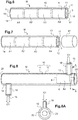
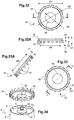
- FIG. 3 One of the types of rigid cylindrical case, usually manufactured for a high capacity Li-ion battery, is illustrated in figure 3 .
- a rigid prismatic case is also shown in figure 4 .
- the case 6 comprises a cylindrical lateral casing 7, a bottom 8 at one end, a cover 9 at the other end, the bottom 8 and the cover 9 being assembled to the casing 7.
- the cover 9 supports the poles or terminals of current output 4, 5.
- One of the output terminals (poles), for example the positive terminal 4 is soldered to the cover 9 while the other output terminal, for example the negative terminal 5, passes through the cover 9 with the interposition of a seal (not shown) which electrically isolates the negative terminal 5 from the cover.
- the type of rigid case widely manufactured also consists of a stamped cup and a cover welded together on their periphery by laser.
- the current collectors include a bushing with a part projecting from the top of the case and which forms a terminal also called the apparent pole of the battery.
- the difficulty in producing such a terminal lies mainly in the assembly of the various components of the battery in order to have a robust design.
- the nature of the materials used is also important in order to be compatible with certain electrochemical couples. Indeed, Li-ion technology preferably requires selecting a grade of aluminum as pure as possible inside the accumulator to avoid the presence of pollution and the generation of galvanic torque in the presence of the electrolyte can lead to corrosion.
- a battery pack P consists of a variable number of accumulators up to several thousand which are electrically connected in series or in parallel with one another and generally by connection bars, usually called, busbars.
- FIG. 5 An example of P battery pack is shown in figure 5 .
- This pack consists of two identical modules M1, M2 of Li-ion batteries A and connected together in series, each module M1, M2 consisting of four rows of batteries connected in parallel, each row consisting of a number equal to six Li-ion batteries.
- busbars B1 advantageously made of copper, each connecting a positive terminal 4 to a negative terminal 5.
- the connection between two rows of accumulators in parallel within the same module M1 or M2 is provided by a busbar B2, also advantageously made of copper.
- the connection between the two modules M1, M2 is provided by a busbar B3, also advantageously made of copper.
- a lithium electrochemical system whether at the cell, module or pack scale, produces exothermic reactions whatever the given cycling profile.
- the optimal functioning of lithium ion accumulators is limited within a certain temperature range.
- An accumulator must control its temperature, typically generally less than 70 ° C at its outer surface of the case, in order to avoid going into thermal runaway which can be followed by a generation of gas and explosion and / or fire.
- maintaining a temperature below 70 ° C. makes it possible to increase its service life, because the higher the operating temperature of an accumulator, the more its service life will be reduced.
- the dispersions of aging can be high depending for example on the position of the accumulators, following asymmetries of aging between the accumulators or differences in uses ( thermal variations between the core and the edges of the pack, current gradient ).
- differences in SOH health states of the order of 20% between accumulators in the same pack can be observed.
- the BMS (English acronym for " Battery Management System ”) is used to monitor the state of the various accumulators (state of charge, state of health, etc.) and to control the various safety elements, such currents should not be too high, unsuitable potentials (too high or too low), limit temperatures and therefore has the function in particular of stopping current applications as soon as threshold voltage values are reached, ie a potential difference between the two active insertion materials.
- the BMS therefore stops current applications (charging, discharging) as soon as threshold voltages are reached.
- a battery pack generally requires a very efficient BMS, in order to generate voltage balances.
- thermally balanced battery pack is also a necessity.
- the difficulty arises in ensuring uniformity of temperature within a battery pack.
- the first category concerns solutions where a heat transfer fluid (gaseous or liquid) is circulated within a battery pack.
- the patent US5320190 thus offers air circulation to cool a vehicle battery pack, either by directly using the air impacting the vehicle during taxiing, or by using a fan for the parked phases or just after taxiing.
- the patent CN202259596U offers a battery pack that incorporates air distributors.
- Coolant can be used in place of air.
- the concepts of cost, size and additional mass can be major factors depending on the application considered.
- air cooling is the least expensive solution since, as indicated, it consists of forced air ventilation between the accumulators.
- thermal performance of air cooling is of poor quality due to the low exchange coefficient and its low thermal inertia.
- the first accumulator will nevertheless heat up in contact with the air and the air temperature will increase.
- the second accumulator passes, the air is warmer and the accumulator is warmer than the first. In the end, we thus obtain accumulators whose temperature is inhomogeneous.
- Liquid cooling solutions are much more effective.
- patent applications WO2008 / 156737 and US2013 / 196184 propose a system of channels which each follow a part of the periphery of several cylindrical accumulators parallel to each other A heat transfer liquid flows inside these channels to drain the heat.
- the patent US8877366 relates to a liquid cooling solution flowing in external tubes which cool by thermal conduction of the fins inserted between accumulators.
- the second category concerns the use of cold plates.
- the patent application WO2011 / 013997 proposes cooling fins arranged inside a stack of flat cells to drain the heat from the cells towards a fluid circulating at the bottom of the stack.
- the third category concerns cooling by phase change material. So the patent application US2006 / 0073377 proposes to regulate the temperature of the cells which are embedded in the phase change material. The material is placed inside a rigid envelope which contains the electrochemical cells and fills the spaces between the adjacent cells.
- the object of the invention is to meet these needs at least in part.
- the invention consists in defining a completely independent module with a tube which serves as a housing for a plurality of accumulators aligned one after the other, the accumulators being electrically connected together in series and fluidly by a common circuit coolant which will flow continuously in the heart of the electrochemical bundles of all the accumulators and / or in an external envelope defined by the housing tube, in contact with the accumulator boxes.
- the thermal of a complete battery pack can be managed in a modular manner by connecting in series or in fluidic parallel therebetween several accumulator modules which are further connected together in series or in electrical parallel.
- the cooling or heating of a battery pack is simplified.
- the N accumulators can be divided into several modules M. If the N accumulators operate in the same way, it is advantageous to have the same flow rate within each of the M modules. If certain accumulators N operate differently and therefore heat more, it is also possible to regulate the flow rate of each of the M modules.
- the reservoir can be a closed double-walled tank, the inner or outer wall of which is defined by the tube, the closed double-wall being filled with a phase change material (MCP).
- MCP phase change material
- the circuit can comprise a double-walled conduit, the internal or external wall of which is defined by the tube, the double-wall being emerging at one of its ends by a fluid supply orifice and to the other of his ends by a fluid outlet orifice, to circulate the heat transfer fluid over the entire periphery of the accumulator boxes, from the inlet orifice to the outlet orifice.
- the module may include two sealed fluid connections, each passing longitudinally through the interior of one end of the double wall.
- each of the closure elements comprises an electrically conductive central part, forming the electrical output terminal of the module and a peripheral part, around its central, electrically insulating part.
- the double-walled conduit can be constituted by two concentric tubes distinct from the accumulator boxes, the inner tube being in direct contact with the lateral envelopes of the accumulator boxes.
- the inner wall of the double-walled conduit is delimited by the lateral envelopes of the accumulator boxes, the outer wall being constituted by the tube.
- the module comprises centering means either between the inner tube and the outer tube, or between the side envelopes of the housings and the outer tube.
- the centering means can be constituted either by a plurality of fins or inserts distributed uniformly on the periphery of the inner tube or the lateral envelopes of the housings, or by a helically shaped fin wound around the inner tube or around side casings of the cases, either by a foam homogeneously filling the volume between the inner tube and the outer tube or between the side casings of the cases and the outer tube.
- means of electrical insulation are provided between the fins or foam and the inner tube.
- the invention also relates to a battery module (M) according to the first alternative in combination with the second alternative.
- the invention also relates to a battery pack comprising a plurality of modules (M) of accumulators described above, electrically connected in series or in parallel, with the plurality of coolant circuits fluidly connected in series or in parallel.
- the system comprises a safety member to protect the expansion tank from overpressure caused by the gases of the accumulators.
- the safety device is preferably a valve, and / or a regulating device controllable by the battery pack accumulator control system (BMS).
- BMS battery pack accumulator control system
- the invention also relates to a metal-ion electrochemical battery or accumulator, for a monitoring system as described above, comprising a rupture membrane permeable to gases and impermeable to the heat transfer fluid, the membrane being arranged and fixed in the accumulator for allow the gases released by the accumulator to pass outside of the latter.
- the membrane is in the form of a disc sandwiched on the through hole by means of a metal crown welded to the electrically conductive part.
- the electrically conductive part is preferably a male part projecting from the accumulator case.
- the male part is preferably made of nickel-plated copper or aluminum alloy
- the male part may include, in its lower part, below the second diameter enlargement, a reduction in diameter integrating the through hole on which the rupture membrane is fixed.
- the crossing can be carried out through the cover of the case, which is advantageously made of aluminum, such as aluminum 1050 or 3003.
- the rupture membrane is arranged in the empty volume delimited between the cover and the current collector of the electrical connection between the terminal and the electrochemical cell of the accumulator.
- the annular groove is advantageously dimensioned to produce a fitting with a tight fit on the top of the accumulator case.
- the collar further comprises a plurality of spacer tabs distributed at the periphery of the annular wall, the tabs being adapted to guarantee a fixed spacing with an outer tube in which the aligned accumulators are housed coaxially.
- the spacer tabs are distributed uniformly according to a spacing step e5.
- the collar is shaped so as to leave an empty volume between the flat base which is applied against the cover of the case of one of the two accumulators and the bottom of the case of the other of the accumulators.
- the part is produced by injection of a plastic material, in particular a PA6-6 or a polyoxymethylene (POM).
- a plastic material in particular a PA6-6 or a polyoxymethylene (POM).
- the two accumulators are also advantageously assembled together by means of the output terminal of one of the accumulators screwed onto the hollow mandrel of the other of the accumulators, through the bottom of the latter.
- an electronic module is provided supported by the flat base in the empty volume or integrated into the thickness of the flat base, the electronic module being adapted to monitor the electrical characteristics of one or the other of the accumulators.
- the electronic module is electrically supplied on the one hand by a wire of a polarity, through the flange to connect it electrically to the cover of the accumulator on which the flat base of the the flange is supported on the other by another electrical supply wire, of opposite polarity, to connect it electrically to a part of the output terminal of the accumulator.
- the invention also relates to a battery pack comprising one or a plurality of accumulator modules described above and a control system for all the accumulators (BMS) to which all the accumulators are electrically connected by an electric power circuit configured of such that the voltage increases from the electronic modules to the BMS are made by line carrier currents (CPL) on said circuit.
- BMS accumulator modules
- CPL line carrier currents
- Each of the electronic modules can be electrically connected to another of the electronic modules by means of one or more so-called redundancy electric wires.
- Each flange can advantageously integrate into its side wall a connection connection between two redundancy wires, one being directly connected to an electronic module, the other being connected to another electronic module.
- the wire connected between the connectors and the other electronic module is fixed, in particular by gluing, along the wall of the accumulator adjacent to that supporting the electronic module.
- the male part comprises an annular groove adapted to accommodate an O-ring seal.
- the invention also relates to an accumulator module, comprising at least two accumulators described above, the accumulators being assembled together by means of the bushing forming an output terminal of one of the accumulators screwed to a hollow mandrel of the other of the accumulators, through the bottom of the latter.
- the bushing is preferably screwed into the hollow mandrel according to a tightening torque at least equal to 3 N.m.
- the invention also relates to a battery pack comprising one or more accumulator modules as described above.
- the terminal piece, the mandrel and the electrical insulation element are assembled together according to a magnetic pulse welding process, or by bonding, or by shrinking, or by brazing.
- the terminal part comprises a thread intended to cooperate by screwing with another thread for fixing and the electrical output of the accumulator.
- the mandrel comprises a thread intended to cooperate by screwing with another thread for the fixing and the electrical outlet of the accumulator.
- the mandrel is preferably made of aluminum, preferably made of 99.5% pure aluminum (1050A).
- the invention also relates to a metal-ion battery or accumulator comprising a sub-assembly which has just been described, the terminal piece of which constitutes a portion of the bushing of the cover of the accumulator case, and the mandrel of which crosses the bottom. of the case by being welded to it.
- the invention finally relates to an accumulator module, comprising at least two accumulators as above, the accumulators being assembled together by means of the bushing forming output terminal of one of the accumulators screwed to the hollow mandrel of the other accumulators, through the bottom of the latter.
- the bushing is advantageously screwed into the hollow mandrel according to a tightening torque at least equal to 3 N.m.
- the Figures 1 to 5 relate to different examples of Li-ion accumulator, boxes and bushings forming terminals as well as a battery pack according to the state of the art. These Figures 1 to 5 have already been commented on in the preamble and are therefore not further discussed below.
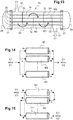
- the stack of accumulators A1-A4 aligned one after the other and connected together in electrical series is housed in a double-walled envelope 10.
- the A1-A4 batteries shown are cylindrical in size.
- the double-walled envelope 10 consists of two concentric tubes 11, 12, arranged coaxially around the accumulators.
- the space between the inner tube 11 and the outer tube 12 defines a volume of heat transfer fluid over the entire periphery of the accumulator boxes.
- the envelope 10 may constitute a closed double-walled reservoir 11, 12 filled with a phase-change material (MCP) of the solid-liquid type. It is thus possible to generate a constant liquid temperature over the entire length of the casing 10, and therefore over all the heights of the accumulators A1-A4.
- MCP phase-change material
- the casing 10 can be a double-walled conduit, emerging at one of its ends 13 by a supply orifice 15 of heat transfer fluid and at the other of its ends 14 by an outlet orifice 16 for the fluid.
- a heat transfer fluid C1 over the entire periphery of the accumulator boxes, from the inlet orifice 15 to the outlet orifice 16.
- One or more compression elements such as springs or blades, can be arranged inside the inner tube 11 and at one or both ends 13, 14 of the tube 11 in order to ensure the longitudinal positioning of the assembly inside the tube while guaranteeing the electrical insulation with respect to the tube which must remain at a neutral potential, that is to say different from the positive pole of the box or the negative pole of the terminal passing through the cover.
- the inner tube can either be a separate tube 11 of the accumulator boxes 6, or be delimited by the lateral envelopes of the cases 6. In other words, when it is a separate tube 11, the accumulators A1-A4 are fitted inside it, preferably with direct contact.
- the lateral casings of housings 6 of aligned A1-A4 accumulators can delimit the inner tube 11.
- This alternative embodiment makes it possible to remove an inner tube and therefore to reduce the thermal resistance between heat transfer fluid and accumulators A1-A4, this which therefore generates better heat exchanges.
- the electrical connection in series is advantageously made by an output terminal 5 which projects from the housing 6 of an accumulator, with the bottom 8 of the housing 6 from an adjacent accumulator and the electrical output of the module M is leaves via the output terminal 5 of the accumulator A4 at one end 13 and through the bottom of the accumulator A1 at the other end 14.
- An advantageous embodiment of output terminal 5 according to the invention is described more far.
- the supply of heat transfer fluid which is a cooling fluid (liquid or gas or refrigerant) when it is desired to cool the accumulators A1-A4 in operation, can be done directly with flexible or other that is sleeved then that the 'fixed at the ends 13, 14 of the module.
- the fixing can be ensured by screwing, welding or brazing.
- This sealed connection sleeve 17 passes longitudinally through the interior of one end 13 of the double wall 11, 12.
- sleeves which each relate to a fluid collector 18, 19 passing laterally through one end 13, 14 of the double wall.
- two sealed closure elements 20, 21 each close longitudinally one end 13, 14 of the double wall.
- the closing element 20 can also directly constitute one of the two output terminals of the module M. In this case, it is necessary to electrically isolate it from the tubes 11, 12. To do this, as shown in FIGS. 8 and 8A, a block of insulating material 22 is arranged around the terminal 5 and the closure element 20. A similar insulating block, not shown, is arranged at the other end of the module.
- a second alternative according to the invention for managing the thermal of a module M consists in circulating a heat transfer fluid in all of the hearts of accumulators A1-A4.
- the aim is to produce a continuous flow of this fluid through all of the mandrels which have the primary function of serving as the winding core of an electrochemical cell before its housing in a housing. accumulator.
- the mandrels are hollow and also serve as a heat transfer fluid circulation conduit, all of the hollows being hydraulically connected in series within the same module M.
- the invention therefore makes it possible to have a combined circulation of a heat transfer fluid C1 at the periphery of the accumulators A1-A4 with a heat transfer fluid C2 at the heart of the accumulators A1-A4.
- the heat transfer fluids C1 and C2 can be the same fluid or be distinct. Depending on the geometry and / or the chemistry of the electrochemical cells, it is thus possible to choose a fluid C1 with thermal or dielectric characteristics, different from those of the fluid C2.
- the circulation of the fluid C1 may be co-current with that of C2 or even in the opposite direction of flow, that is to say in counter-current to C2.
- This counter-current circulation can make the temperature of accumulators A1-A4 of the same module even more homogeneous.
- a double-walled conduit 10 therefore consists of an inner tube 11 either filled with accumulators A1-A4 in contact with its internal wall, or delimited by the lateral envelopes of the housings 6 and a tube exterior 12 concentric with the interior tube 11, 6.
- the annular space E between internal tube 11 and external tube 12 therefore defines the cross section of the heat transfer fluid C1.
- the annular space E can advantageously vary between 1 mm and 20 mm, depending on the size and the power of the accumulators.
- the centering means may consist of fins or inserts 23 of straight shape, fixed on at least one of the two tubes 11, 12 which extend along the axis of the tubes by being uniformly angularly distributed as shown in figure 11 .
- These fins or inserts 23 also have the advantage of being able to increase the surface area for exchange with the heat transfer fluid C1 which will circulate in the annular space E.
- a material constituting the fins 23 which is a good thermal conductor (aluminum, copper, ...), we may be able to multiply the exchange surface between the fluid C1 and the internal tube 11 by a factor of about 1 to 5, and therefore reduce the temperature difference between fluid C and accumulators A1-A4 of the same factor.
- care is taken to size the fins or inserts 23 so that they do not obstruct the cross section of the fluid C1 in order to have acceptable pressure drops. In the context of the invention, care must also be taken not to produce a short circuit via the tube if the fins are electrically conductive.
- the figure 12 shows an alternative embodiment according to which a single helical fin 24 is crimped around the inner tube 6, 11.
- This helical fin 24 allows also to increase the exchange surface and to intensify the heat exchange, due to the propeller 24 which also allows the coolant to rotate.
- this exchanger 25 a bundle of modules (M1, M2, M3, M4, etc.) of accumulators is housed in a sealed hollow body forming a shell 26 which will act as an external wall for guiding the heat-transfer fluid while the inner wall is provided for each module (M) by a single tube 11 inside which are housed the accumulators aligned and electrically connected in series. With such an exchanger 25, there is no longer any peripheral flow in a double wall 10 and the heat transfer fluid travels outside the tubes 11.
- the exchanger 25 comprises two tubular holding plates 27 each pierced with a plurality of orifices 28 parallel to each other.
- the number of orifices is equal to that of the plurality of tubes 11 of the modules (M) of accumulators.
- each of the two ends of each tube 11 is engaged in a holding orifice 28 of a tubular plate 27 while being fixed in leaktight manner to the latter.
- the grille 26 is tightly fixed around the tubular plates 27 to delimit the coolant circuit.
- the calender 26 comprises at one of its ends an inlet orifice 30 for heat transfer fluid and at the other of its ends an outlet orifice 31 for fluid.
- baffles 32 are arranged inside the calender 26 for guiding the flow of the heat transfer fluid C1.
- the baffles 32 are constituted by plates extending transversely to the tubes 11 and parallel to the end tubular plates 27, being regularly spaced along the tubes and closing part of the cross section of the shell, to guide the heat transfer fluid around the tubes 11 of the accumulator modules (M1, ... M4).
- the baffles then also make it possible to support the mass of the tubes 11 filled with accumulators (A1-A4) and thus avoid the bending of the tubes 11 under the weight of the accumulators.
- two electrical collectors 29 make it possible to house a plurality of electrical connections connected to the plurality of M1-M4 accumulator modules for electrically connecting all these modules to each other.
- the exchanger 25 cooled by the heat transfer fluid C around the accumulators A1-A4 of each module and possibly at the heart of each of them, constitutes in itself, once the electrical connections in series or in parallel between the different modules M1 to M4, a battery pack.
- a module M of accumulators formed according to the invention constitutes an autonomous assembly with a number of X of accumulators in series which one can easily handle, put in place where one wishes to connect fluidly and electrically with other modules accumulators according to the invention.
- the modules M are combined in series or fluid parallel. Indeed, the fluid heats up progressively and one can then have temperature differences between the first and the last accumulator of the same module.
- the figure 14 illustrates a configuration of battery pack P according to which the circulation of the heat transfer fluid C1 and / or C2 is ensured in parallel between all the modules M1, M2 ... Mn while they are connected in electrical series with one another.
- the figure 15 illustrates a configuration of battery pack P according to which the circulation of the heat transfer fluid C1 and / or C2 is ensured in series between all the modules M1, M2 ... Mn while they are connected in electrical parallel to each other.
- a circulation of heat transfer fluid only in series has the advantage of not causing any problem in the distribution of fluid since all the accumulators are in contact with the same flow of fluid, unless the fluid heats up along the flow.
- one solution consists in connecting them by connecting a terminal 5 to the center of the cover 9 of the casing of an accumulator to the terminal opposite 4 located on the bottom 8 of the case of an adjacent accumulator.
- the inventors have thought of producing a hollow sub-assembly 33 comprising a hollow mandrel 34 and a hollow output terminal part. 5 in the continuity of the hollow mandrel 34.
- This sub-assembly must induce a minimum or even no pressure drop for the circulation of the coolant. In addition, it must guarantee a perfect seal with the interior of the accumulator, in order to avoid any contact between the heat transfer fluid and the electrolyte of the accumulator.
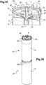
- a sub-assembly 33 is shown with its components 5, 34, 43 in Figures 16 to 23 .
- FIGS. 16 and 17 show the interior of an accumulator A which integrates such a subset 33 therein.
- the hollow mandrel 34 retains its primary function and supports the electrochemical cell C which is wound around during its winding.
- the diameter of the mandrel 34 thus respects the winding conditions of a cell C in order to generate the desired electrochemical performance of the accumulator.
- the end 35 of the mandrel 34 opposite to that in connection with the terminal 5, includes a thread 35.
- the threaded mandrel 34 and the bottom 8 of the housing 6 therefore constitute the other terminal 4 of the accumulator, typically the positive terminal in the case of a Li-ion accumulator.
- the part 5, hollow in its center, which forms a male part of the output terminal is shown alone in figure 18 . It firstly comprises in its upper part a thread 36 adapted to cooperate with the thread 35 of the mandrel 34 of an adjacent accumulator to make the electrical and mechanical connection between two accumulators.
- a groove 37 is produced below the thread 36, in order to be able to accommodate there a seal 38, for example made of PTFE.
- the part 5 comprises a first enlargement of diameter 39 which serves as the crimping diameter of a female part 50 of the output terminal as described below, and a second enlargement of diameter 40 in the continuity of the first which serves as both a support surface with an electrically insulating washer and a surface for connection to a current collector which makes the electrical connection with the cell as described below.
- the part 5 comprises two reductions in diameter 41, 42, the end of which is adapted to be fitted inside the mandrel 34.
- the terminal 4 constituted by the hollow mandrel 34 typically the positive terminal, of the hollow terminal piece 5, typically the negative terminal.
- the hollow sub-assembly 33 comprises a mechanical connection and electrical insulation part 43 shown in detail in figure 19 .
- flange 44 In its upper part a flange 44 and in its lower part a cylinder 45.
- the dimensioning of the parts and their positioning are chosen so that the flange 44 extends above the base 52 of current collector 51 described by after.
- This connecting piece 43 being made of electrically insulating material, it is necessary to guarantee a mechanically robust and perfectly sealed assembly of this piece 43 with the terminal piece 5 and the mandrel 34 both made of electrically conductive material.
- Magnetic Pulse Welding is a process based on the use of electromagnetic forces to weld parts together.
- Such a method consists in arranging the different parts to be welded in an induction coil but without contact with it. During the welding cycle, a very large amount of electrical energy is released in a very short period of time. Thus, the high energy flow crosses the coil and this current discharge induces eddy currents in the external part to be welded. These two currents create a magnetic field. The repulsion between the two magnetic fields develops a force which gives a very great acceleration to the external part to be welded in direction of the internal part. Such a force pushes the atoms of materials against each other so that a metallic connection is obtained between internal and external parts.
- the magnetic pulse welding process is a cold welding process, in which the materials to be welded do not reach more than 30 ° C, no area of the parts is affected thermally and the material does not lose its properties . This means that after welding, the parts can be immediately released and implemented. The absence of heat during the welding cycle makes it possible to assemble materials having a very different melting point. In addition, during the magnetic pulse welding cycle, the metal of a part is not melted. Finally, a magnetic pulse weld is stronger than the weakest base metal.
- a hollow sub-assembly 33 produced by a magnetic pulse welding process, guarantees on the one hand the perfect seal between the electrolyte present in the accumulator and the heat transfer fluid which will circulate inside the sub-assembly and on the other hand the perfect electrical insulation between the polarities of the accumulator between the cover and the bottom.
- the male part 5, preferably produced by one-piece machining can be made of aluminum or copper. More preferably, the material is pure copper (CuAl. For corrosion reasons, a nickel-based surface treatment can be deposited on the surface. The diameter enlargements 39, 40 can be applied to the workpiece 5 by laser welding or shrinking in order to reduce the cost of machining / material Finally, the height of the part 5 is optimized, so as not to machine very long but also in order to reduce material costs.
- the hollow mandrel 34 is preferably made of aluminum. More preferably, the material is 99.5% pure aluminum (1050A) which is usually the material of the cup 7 and of the bottom 8 of an accumulator case 6. This provides the best chemical compatibility for welding, in particular by laser, between the mandrel 34 and the bottom 8.
- the electrical insulation part and mechanical connection 43 is preferably made of rigid plastic with very good chemical inertness, and preferably produced by machining or by injection.
- the part 43 is preferably made of polypropylene (PP) or polyetherimide (PEI), which have the advantage of being resistant with the usual electrolytes of accumulators and an oil as heat transfer fluid while having good mechanical characteristics at the deformation.
- the part 43 can undergo a coating treatment, for example with a mixture of ferrite and insulating resin, in order to make it ferromagnetic to apply the solder while remaining insulating from a current flow point of view.
- the mechanical clearances during assembly before assembly by welding between the three parts 5, 34, 43 are chosen to guarantee the fitting of the parts together but also to ensure sealing.
- the hollow sub-assembly 33 internally defines a continuous and sealed passage of the heat transfer fluid C2 over the entire height of the accumulator.
- the inside of the diameter reduction portion 41 can advantageously be provided at the end of the latter with a chamfer 46.
- the chamfer 46 is 1 mm in height , with an inclination of 45 °.
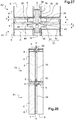
- the crossing is carried out through an orifice 47 opening on either side of a cover 9 of an accumulator case A.
- the crossing comprises first of all two identical electrically insulating washers 48, 49. These two insulating washers 48, 49 have the function of ensuring sealing against the electrolyte within the accumulator on which the crossing is made, vis-à-vis the outside of the cover 9. In addition, they provide electrical insulation between the room terminal 5 male and cover 9.
- each washer has a support portion and a guide portion projecting from the support portion.
- the bearing portion of the upper washer is in surface support with pressure against the upper face of the cover 9 and its guide portion is in contact with the edge of the orifice 47 of the cover 7.
- the portion of support of the lower washer 49 is in surface support with pressure against the lower face of the cover 7 and its guide portion is in contact against the edge of the orifice 47 of the cover 7.
- the electrically conductive male part 5 is adjusted clamped by its enlargement of diameter 39 in a female annular part 50, opening out at its center, which is also conductive.
- the female annular part 50 is therefore crimped around the enlarged diameter 39 of the male part 5 and presses against the upper insulating washer 48.
- the different dimensions of the components of the terminal are such that, in this assembled configuration, the thread 36 in the upper part of the male part 5 protrudes beyond the female part 50 and the O-ring seal 38 is interposed between them.
- this female part 50 by its annular surface makes it possible to provide the electrical connection between the terminal 5, 50, typically at the negative pole, of an accumulator A2 and the bottom 8 of the housing 6 of the accumulator adjacent A1 to the positive pole by a plate ensuring the cross section for strong currents.
- the thread 36 is used for connection between the output terminal of an accumulator A2 with the bottom 8 of case 6 of an adjacent accumulator A2. More precisely, the thread 36 which cooperates by screwing with the thread 35 of a hollow mandrel 34 makes it possible to guarantee a high level of tightening, typically of the order of 3N / m between two adjacent accumulators A1, A2, and therefore a resistance less contact, of the order of 12 to 15 mohm.
- the O-ring 38 therefore seals the heat transfer fluid C2 at this threaded junction 35, 36, the tightening of the seal being controlled by the adjustment between the bottom of the groove 37 and the internal diameter of the hollow mandrel 34.
- the crimping pressure generates a compression along the X axis of the bushing which is the central axis of the accumulator.
- the inventors carried out different crimping tests by increasing the thickness E of the base of the male part 5 of the terminal according to the invention.
- This base is formed by the enlargement of diameter 40.
- the value of the thickness E of the base 40 is all the more important as the diameter ⁇ of bore 39 is large because the more this diameter increases and, the more the crimping force must be important.
- the term “robust mechanical connection” within the meaning of the invention means a connection which makes it possible to meet the required specifications, in terms of mechanical resistance of this type of terminal which constitutes a terminal terminal or the output of an accumulator, it i.e. a tensile strength, a tightening torque strength, a vibration resistance, a mechanical shock resistance, a resistance to temperature variations (-40 ° C / + 75 ° C), ...
- the female part 50 can be of 5754 aluminum grade or copper or nickel-plated copper.
- Aluminum 5754 has the advantages of having very good mechanical characteristics and remains intact when pressure is applied to its surface, in particular during crimping according to the invention.
- the nickel-plated copper is advantageously of the same nature as that defined for a conventional copper negative terminal, which makes it possible to maintain an identical interface for a user.
- the male part 5 is preferably made of nickel-plated copper because it is compatible with the materials constituting the electrochemical core of a Li-ion accumulator (chemistry of electrode materials, electrolyte based on LiPF6, etc.). But, as already mentioned, the male part can just as easily be made of aluminum.
- the insulating washers 48, 49 are advantageously made of polyethrimide (PEI).
- the dimensioning of the different parts of the output terminal, and in particular the height H1 of the female part 50 ensures a minimum separation distance d between two boxes 6 of adjacent accumulators A1, A2.
- this distance d is at least equal to 1 mm, preferably between 1 and 5 mm.
- a metal current collector 51 illustrated as as in figure 29 .
- This current collector 51 comprises a flat base 52 which is welded at the top of the electrochemical bundle C to the metal strip supporting the active material of the electrode and a tongue 53 folded back on itself and welded to the enlargement of diameter 40 of the male part 5 of the terminal.
- This base 52 and tongue 53 therefore provide electrical continuity between the electrode and the output terminal, of given polarity.
- a cooling / reheating circulation mode consists in circulating the heat transfer fluid on the periphery of the accumulators A1-A4 within the same module, with direct contact on the side envelopes of their housings, that is to say, by dispensing with an additional inner tube 11.
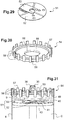
- This interface piece 54 forming a collar is shown as such in figure 30 . It comprises first of all a flat base 55 pierced with a through opening 56 whose diameter is adapted to that of the female part 50 which is housed there.
- the flat base 55 is surrounded by an annular wall 57 which comprises a plurality of spacer lugs 58 distributed uniformly at the periphery of the annular wall 57 according to a spacing pitch e5.
- These legs 58 have the function of guaranteeing a spacer, that is to say of guaranteeing a fixed spacing with an external tube 12 in which are housed the accumulators A1-A4 assembled together of the same module M.
- the side wall 57 is further shaped to delimit an annular groove 59 of complementary shape with that of the top of an accumulator case 6, that is to say complementary to the upper shape of the lateral envelope 7 and of the cover 9 which is welded thereto.
- an interface piece or flange 54 is adapted to be fitted by its annular groove 59 on the inner rim of the cover 9 of the casing 6 and the top of its lateral envelope 7.
- This fitting can be done manually and the dimensions of the collar 54 advantageously allow tightening during assembly.
- the tightening obtained with the flange 54 according to the dimensions indicated in the table is 0.2 to 0.25 mm for the minimum cover dimension , or from 0 to 0.05 mm for the maximum dimension of the cover.
- the collar 54 can advantageously be produced by injection of a plastic, in particular a PA6-6 or a polyoxymethylene (POM) such as that sold under the brand Delrin. .
- a plastic in particular a PA6-6 or a polyoxymethylene (POM) such as that sold under the brand Delrin.
- the figures 34 and 35 show the collar 54 respectively before and once it has been tightened in place on an accumulator case 6.
- the flange 54 makes it possible to guide the adjacent accumulator A2, during the electrical connection between terminal 5 and hollow mandrel 34. The guidance is therefore carried out via this flange 54 and the outer periphery from the bottom 8 of the accumulator case.
- the figures 36 and 37 show the outside of a part of a module M with the accumulators A1-A4 electrically connected to each other, assembled by their terminals 5 and hollow mandrel 34, and guided and spaced from one another by the flanges 54 arranged individually between them .
- this assembly is in turn inserted into a tube 12 which will constitute the outer tube of the double-walled conduit 10 for the circulation of the heat transfer fluid C1 at the periphery of the accumulators, the double-wall being delimited internally by the lateral envelopes of the housings 6 accumulators.
- the guiding of the accumulators A1-A4 is ensured by the outside diameter of the flange 54, that is to say by the outside diameter ⁇ 1 of the spacer tabs 58.
- this internal diameter is also dimensioned as a function of the external diameter of the flange 54 and the thicknesses of the legs. spacer 58, so as to control the pressure losses of the heat transfer fluid while taking care to block the accumulators and withstand in particular vibrational stresses.
- the additional function of the collar 54 which has just been described is to electrically isolate the accumulators A1-A2 from each other, during and, once the connection by the output terminal 5 has been made.
- the figure 39 illustrates this function well where it is clearly seen that by the shape of the collar 54, any contact between two boxes 6 of adjacent accumulators, and more particularly between the cover 9 of one and the bottom 8 of the other is prohibited.
- the inventors have also thought of assigning the collar 54 another function. Indeed, as shown in figures 40A and 40B , the inventors have defined a collar 54 which, once the assembly between adjacent accumulators has been carried out, leaves a volume V free between the base 55 of the collar 54 and the bottom 8 of the adjacent housing 6.
- each electronic module 60 or microcontroller may include at least one memory, a communication module adapted to receive and / or transmit data from and / or to the outside of each accumulator and a processor adapted to receive and / or transmit at least data from and / or to the communication module.
- the inventors therefore thought of using the base 55 of the collar 54 as a support for an electronic module 60, as shown in Figures 41A and 41B .
- the electronic module 60 can be fixed by gluing or other means on the base 55.
- the supply of an electronic module 60 is advantageously provided by the terminals of an accumulator. As shown in figures 41B one can thus pass a wire 61 of electrical supply of a polarity through the flange 54 to connect it electrically to the cover and another wire 62 of electrical supply 62, of opposite polarity to connect it electrically to the female part 50 from the terminal.
- the electrical supply wires 61, 62 independently supply the electronic module 60 with the current delivered by the accumulator.
- the figure 42 shows a variant according to which the electronic module 60 is embedded by thermoforming in the thickness of the base 55 of the collar 54.
- the figure 43 shows the equivalent electrical diagram of a module M of accumulators A1-A2 connected to a BMS 70, and each supplying an electronic module 60.
- the voltage rises from the electronic modules 60 to the BMS are made by carrier current CPL on the circuit of power from accumulators A1-A2.
- a variant of this embodiment consists in connecting all the electronic modules 60 together so that the BMS 70 can communicate directly with these electronics, in order to have physical redundancy on the rise in voltages.
- connecting wires 64, 65 between modules 60.
- a first connecting wire 64 is connected from the module 60 to a connector 64 arranged in the thickness of the external edge 57 of the flange 54 then a second connecting wire 65 is preferably fixed by gluing to the lateral envelope 7 of the case 6 of the accumulator, in order to connect each of the connections on the flanges 54.
- these connecting wires 64, 65 very little or no additional pressure drop is introduced into the heat transfer fluid C1.
- the figure 46 shows the equivalent electrical diagram with redundancy by wires 63, 65 and connections 64.
- An expansion vessel 90 is installed on this circuit.
- the gases generated in the heat transfer circuit are therefore recovered in the sky from the expansion tank 90.
- a safety device can be provided to protect the expansion tank from overpressure in the gaseous air, in particular a valve, and / or a regulating device controllable by the BMS.
- the inventors have thought of implanting a rupture membrane or rupture seal directly within each output terminal of an accumulator according to the invention.
- the male part 5 is pierced at its diameter reduction 41 with a through hole 66 which joins the interior of the part.
- a rupture membrane 67 which forms a vent.
- This rupture membrane 67 is gas permeable and impermeable and compatible with a coolant.
- An advantageous type of membrane is described in the patent application WO 1996/016288 A1 .
- the vent may consist of a membrane in the form of a disc 67 made of gas permeable material and impermeable to the cooling fluid, typically according to demand WO 1996/016288 A1 and a metal crown 68 welded to the part 5 and which sandwiches the membrane 67 on the through hole 66.
- the membrane 67 is arranged on the male part 5 of the terminal of the accumulator, so that it is in the empty volume of the latter, that is to say above the base 52 of collector 51 , where gases are formed during electrochemical operation.
- this membrane 67 also constitutes a safety vent, in the event of gas overpressure. Indeed, in this case, the rupture lines 69 formed in the membrane 67 break and the latter tears.
- the rupture value can be fixed at a maximum gas pressure value of the order of 12 bar.
- the overpressure gases arrive in the sky of the expansion tank and the triggering threshold is exceeded, which leads to the opening of the electrical circuit in series, either of the module concerned, or of the entire battery pack.
- the inventors carried out calculations with thermal simulation to highlight the relevance of the various types of cooling / heating according to the invention.
- the format used for the accumulators is the format 50125, that is to say a diameter of 50 mm and a height of 125 mm.
- an internal heat source equivalent to a discharge at 1C is generated, that is to say about 13 Watts.
- the simulated accumulator according to the invention has a hollow mandrel, that is to say an accumulator perforated over the entire height of its central axis, with an outside diameter equal to 9 mm and an inside diameter of 7 mm.
- the accumulator has a hollow mandrel in which the air is trapped without any real cooling effect given the small volume.
- the accumulators A1-A4 illustrated are of cylindrical format, it is possible to envisage realizing all the characteristics of the invention with accumulators of prismatic format.
- the heat transfer fluid can also be a heating fluid for the preheating of the accumulators or for a permanent temperature maintenance of the accumulators. This may be of interest for certain cell chemistries which typically require an operating temperature well above ambient temperature.
- the magnetic pulse welding process has been described for welding between the electrical insulating part 43 and on the one hand the male part 5 of a terminal and on the other hand the chuck 34 which forms the opposite polarity terminal. It is entirely possible to envisage other joining techniques between these different parts 5, 34, 43 such as hooping and / or bonding.
Landscapes
- Chemical & Material Sciences (AREA)
- Chemical Kinetics & Catalysis (AREA)
- Electrochemistry (AREA)
- General Chemical & Material Sciences (AREA)
- Engineering & Computer Science (AREA)
- Manufacturing & Machinery (AREA)
- Materials Engineering (AREA)
- Inorganic Chemistry (AREA)
- Sealing Battery Cases Or Jackets (AREA)
- Battery Mounting, Suspending (AREA)
- Connection Of Batteries Or Terminals (AREA)
- Secondary Cells (AREA)
- Battery Electrode And Active Subsutance (AREA)
Claims (12)
- Durchführung, welche einen Anschluss für einen elektrochemischen Metall-Ionen-Akkumulator bildet, durch eine Öffnung (47) hindurch ausgebildet ist, die beiderseits einer Wand (9) des Gehäuses des Akkumulators mündet, und aufweist:- einen elektrisch leitenden Steckteil (5), der innen einen Durchgang umfasst, der dazu bestimmt ist, ein Kühlfluid strömen zu lassen, das entlang der Längsachse des Akkumulators geströmt ist, wobei der Durchgang zur Außenseite des Akkumulators hin mündet;- einen elektrisch leitenden Aufnahmeteil (50), der mit Presssitz um einen Teil des Steckteils herum angeordnet ist, außerhalb des Akkumulators;- zwei elektrisch isolierende Scheiben (48, 49), die jeweils einen Stützabschnitt, der flächig mit Druck gleichzeitig an einer der Seiten der Wand anliegt, und einen Führungsabschnitt, der in Bezug auf den Stützabschnitt vorsteht und mit dem Rand der Öffnung (47) in Kontakt steht, aufweisen; wobei der Stützabschnitt einer Scheibe (48) mit Druck an dem Aufnahmeteil anliegt; wobei der Stützabschnitt der anderen Scheibe (49) mit Druck an einem Teil des Steckteils anliegt;wobei der Steckteil (5) umfasst:• ein Gewinde (36), das dazu bestimmt ist, durch Verschraubung mit einem anderen Gewinde (35) zur Befestigung zur Befestigung und dem elektrischen Ausgang des Akkumulators zusammenzuwirken;• eine erste Durchmesserverbreiterung (39) unterhalb des Gewindes (36), welche als Klemmdurchmesser für den Aufnahmeteil (50) dient, und• eine zweite Durchmesserverbreiterung (40) in der Fortsetzung der ersten, welche gleichzeitig als Anlagefläche für die elektrisch isolierende Scheibe (49) und als Verbindungsfläche zu einem Stromabnehmer (51), der dazu bestimmt ist, die elektrische Verbindung mit der elektrochemischen Zelle des Akkumulators herzustellen, dient.
- Durchführung nach Anspruch 1, welche außerdem eine durchgehende Schweißnaht (S) umfasst, die Rand an Rand zwischen dem Steckteil und dem Aufnahmeteil hergestellt ist.
- Durchführung nach einem der vorhergehenden Ansprüche, wobei der Steckteil (5) eine Ringnut (37) umfasst, die dafür ausgelegt ist, einen O-Dichtring (38) aufzunehmen.
- Durchführung nach einem der vorhergehenden Ansprüche, wobei der Steckteil (5) aus vernickeltem Kupfer oder aus Aluminiumlegierung besteht.
- Durchführung nach einem der vorhergehenden Ansprüche, wobei der Aufnahmeteil (50) aus einer Aluminiumlegierung 5754 oder aus Kupfer oder aus vernickeltem Kupfer besteht.
- Durchführung nach einem der vorhergehenden Ansprüche, wobei die isolierenden Scheiben (48, 49) aus Polyetherimid (PEI) bestehen.
- Metall-Ionen-Batterie oder -Akkumulator, die bzw. der ein Gehäuse (6) mit einem Deckel (9) aufweist, durch den hindurch eine Durchführung nach einem der vorhergehenden Ansprüche hergestellt ist.
- Metall-Ionen-Batterie oder -Akkumulator nach Anspruch 7, wobei der Deckel aus Aluminium besteht, wie etwa Aluminium 1050 oder 3003.
- Lithium-Ionen-Batterie oder -Akkumulator nach Anspruch 7 oder 8, wobei in dem Akkumulator:- das Material der negativen Elektrode(n) aus der Gruppe ausgewählt ist, welche Graphit, Lithium, Lithium-Titanat-Oxid Li4TiO5O12 umfasst;- das Material der positiven Elektrode(n) aus der Gruppe ausgewählt ist, welche LiFePO4, LiCoO2, LiNi0,33Mn0,33Co0,33O2 umfasst.
- Modul (M) von Akkumulatoren, welches wenigstens zwei Akkumulatoren (A1, A2) nach einem der Ansprüche 7 bis 9 umfasst, wobei die Akkumulatoren über die einen Ausgangsanschluss bildende Durchführung eines (A1) der Akkumulatoren, die an einen hohlen Dorn (34) des anderen (A2) der Akkumulatoren durch den Boden (8) dieses Letzteren hindurch angeschraubt ist, zusammengebaut sind.
- Modul (M) von Akkumulatoren nach Anspruch 10, wobei die Durchführung in den hohlen Dorn mit einem Anzugsmoment von wenigstens 3 N.m eingeschraubt ist.
- Batteriepack, welches ein oder mehrere Module (M) von Akkumulatoren nach Anspruch 10 oder 11 umfasst.
Applications Claiming Priority (1)
| Application Number | Priority Date | Filing Date | Title |
|---|---|---|---|
| FR1762152A FR3075477B1 (fr) | 2017-12-14 | 2017-12-14 | Traversee formant borne pour accumulateur electrochimique metal-ion, accumulateur associe |
Publications (2)
| Publication Number | Publication Date |
|---|---|
| EP3499603A1 EP3499603A1 (de) | 2019-06-19 |
| EP3499603B1 true EP3499603B1 (de) | 2020-02-12 |
Family
ID=62143263
Family Applications (1)
| Application Number | Title | Priority Date | Filing Date |
|---|---|---|---|
| EP18212072.5A Active EP3499603B1 (de) | 2017-12-14 | 2018-12-12 | Querleiste, die als klemmenleiste für elektrochemischen metallionen-akku dient, und entsprechender akku |
Country Status (4)
| Country | Link |
|---|---|
| EP (1) | EP3499603B1 (de) |
| JP (1) | JP2019110122A (de) |
| KR (1) | KR20190072482A (de) |
| FR (1) | FR3075477B1 (de) |
Cited By (1)
| Publication number | Priority date | Publication date | Assignee | Title |
|---|---|---|---|---|
| EP4572000A4 (de) * | 2022-11-08 | 2025-12-31 | Lg Energy Solution Ltd | Batterie und batteriepack sowie fahrzeug damit |
Families Citing this family (9)
| Publication number | Priority date | Publication date | Assignee | Title |
|---|---|---|---|---|
| DE102019118160A1 (de) * | 2019-07-04 | 2021-01-07 | F.E.R. Fischer Edelstahlrohre Gmbh | Zelle mit elektrischem Energiespeicher und Gehäuse |
| DE102019118162A1 (de) * | 2019-07-04 | 2021-01-07 | F.E.R. Fischer Edelstahlrohre Gmbh | Zellverbinder für Zellen und Zellmodule und Batteriemodule mit Zellen |
| CN112582731B (zh) * | 2019-09-30 | 2022-09-09 | 比亚迪股份有限公司 | 电池模组 |
| CN112054269B (zh) * | 2020-09-28 | 2025-02-07 | 广东广特新能源有限公司 | 一种电池单体及电池组 |
| DE212020000648U1 (de) * | 2020-09-28 | 2022-01-24 | Zhongshan Wan Energy Technology Co., Ltd | Batterieelement und Batteriepack |
| CN112803087B (zh) * | 2020-12-17 | 2022-11-15 | 上海第二工业大学 | 一种锂电池回收储存装置 |
| CN115663342A (zh) * | 2022-11-03 | 2023-01-31 | 星恒电源(滁州)有限公司 | 一种圆环型锂离子电池 |
| CN116315473A (zh) * | 2022-12-30 | 2023-06-23 | 广汽埃安新能源汽车股份有限公司 | 电池单体、动力电池及用电设备 |
| US20240421406A1 (en) * | 2023-06-14 | 2024-12-19 | Volkswagen Aktiengesellschaft | Devices systems and methods for vehicle power storage |
Family Cites Families (7)
| Publication number | Priority date | Publication date | Assignee | Title |
|---|---|---|---|---|
| JP3759564B2 (ja) * | 1998-09-02 | 2006-03-29 | 三洋電機株式会社 | リチウム二次電池 |
| JP2002231298A (ja) * | 2001-02-02 | 2002-08-16 | Mitsubishi Materials Corp | 電池及びこれを用いた組電池 |
| JP4356314B2 (ja) * | 2002-12-20 | 2009-11-04 | パナソニック株式会社 | 電池及び組電池 |
| FR2928773A1 (fr) * | 2008-03-14 | 2009-09-18 | Peugeot Citroen Automobiles Sa | Dispositif accumulateur d'energie electrique et train comportant une pluralite de tels dispositifs. |
| JP6127967B2 (ja) * | 2011-02-24 | 2017-05-17 | 日立化成株式会社 | 二次電池及びリチウムイオン電池 |
| DE102011105040A1 (de) * | 2011-05-06 | 2012-11-08 | Klaus Ebert | Lithiumsenkundärzellenanordnung |
| FR2989836B1 (fr) * | 2012-04-24 | 2014-05-23 | Commissariat Energie Atomique | Traversee formant borne pour accumulateur electrochimique au lithium et accumulateur associe. |
-
2017
- 2017-12-14 FR FR1762152A patent/FR3075477B1/fr active Active
-
2018
- 2018-12-12 EP EP18212072.5A patent/EP3499603B1/de active Active
- 2018-12-13 JP JP2018233406A patent/JP2019110122A/ja active Pending
- 2018-12-14 KR KR1020180162485A patent/KR20190072482A/ko not_active Abandoned
Non-Patent Citations (1)
| Title |
|---|
| None * |
Cited By (1)
| Publication number | Priority date | Publication date | Assignee | Title |
|---|---|---|---|---|
| EP4572000A4 (de) * | 2022-11-08 | 2025-12-31 | Lg Energy Solution Ltd | Batterie und batteriepack sowie fahrzeug damit |
Also Published As
| Publication number | Publication date |
|---|---|
| FR3075477B1 (fr) | 2021-07-30 |
| JP2019110122A (ja) | 2019-07-04 |
| FR3075477A1 (fr) | 2019-06-21 |
| EP3499603A1 (de) | 2019-06-19 |
| KR20190072482A (ko) | 2019-06-25 |
Similar Documents
| Publication | Publication Date | Title |
|---|---|---|
| EP3499602B1 (de) | System zur nachverfolgung von gasen in einem batteriepaket, entsprechender elektrochemischer metallionen-akku, der eine klemmenbildende querleiste zur integration einer sicherheitsentlüftung für das nachverfolgungssystem umfasst | |
| EP3499603B1 (de) | Querleiste, die als klemmenleiste für elektrochemischen metallionen-akku dient, und entsprechender akku | |
| EP3499606B1 (de) | Mechanisches schnittstellenelement, das auch zur elektrischen isolierung zwischen zwei elektrochemischen metallionen-akkus dient, die auf ihrer längsachse in reihe geschaltet sind, und entsprechendes akku-modul | |
| EP3499608B1 (de) | Untereinheit, die einen hohldorn und einen teil einer hohlen querleiste umfasst, die als klemmenleiste für einen elektrochemischen metallionen-akku dient, und entsprechender akku | |
| EP3764423A1 (de) | Busbar für batteriepaket, der zur elektrischen verbindung mindestens eines akkus des pakets bestimmt ist sowie zur zirkulation einer wärmeübertragungsflüssigkeit in seinem innern für die optimale kühlung des akkus und des batteriepakets, insbesondere im falle von thermischem durchgehen | |
| EP4002572A1 (de) | Metall-ionen-akku mit entgasungsleitung, batteriemodul oder entsprechender batteriepack mit flüssigkeitskühlung | |
| FR3085803A1 (fr) | Pack-batterie d'accumulateurs, comprenant des shunts magnetiques actionnables sur demande pour la commutation electrique d'un ou plusieurs des accumulateurs | |
| FR3085794A1 (fr) | Pack-batterie d'accumulateurs electrochimiques comprenant des dispositifs de deconnexion magnetique passive entre les accumulateurs et des busbars, et le cas echeant de shunt passif d'un ou plusieurs accumulateurs en cas de defaillance d'un de ceux-ci | |
| EP3179532B1 (de) | Dichter querträger vom typ glas-metall, seine verwendung für elektrochemischen lithiumakkumulator und entsprechendes herstellungsverfahren | |
| FR3091789A1 (fr) | Pack-batterie comprenant une pluralite d’accumulateurs relies electriquement entre eux et un systeme de circulation de fluide dielectrique assurant a la fois le refroidissement des accumulateurs et leur serrage | |
| FR3085793A1 (fr) | Procede d'assemblage d'un pack-batterie d'accumulateurs electrochimiques a des busbars par verrouillage magnetique | |
| EP4199190A2 (de) | Gehäuse für ein batteriemodul oder ein batteriepack mit einer wasserdichten membran zur ermöglichung eines zirkulierenden wärmeträgermediums zur optimalen kühlung von modul- oder paketakkumulatoren. | |
| FR3085796A1 (fr) | Dispositif de connexion/deconnexion magnetique entre un accumulateur electrochimique et des busbars, et de shunt magnetique passif de l'accumulateur apres sa chute par gravite | |
| EP3624229B1 (de) | Ausgangsklemme eines elektrochemischen akkus, die einen magnetverschluss zur magnetischen befestigung mit elektrischer leitung mit einer sammelschiene umfasst | |
| EP3840103B1 (de) | Elektrochemischer akku, insbesondere metall-ionen-akku, mit weicher verpackung, die kühlkanäle umfasst, entsprechendes modul und entsprechendes herstellungsverfahren | |
| EP4174996A1 (de) | Elektrochemischer metall-ionen-akkumulator mit einem stromkollektor, der aus einer scheibe aus thermoplastischem polymer besteht, die mit elektrisch leitenden partikeln und/oder fasern gefüllt ist. | |
| EP3840099A1 (de) | Elektrochemischer akku, insbesondere metall-ionen-akku, mit weicher verpackung, die eine oder mehrere kühlflüssigkeitsdurchlassöffnungen umfasst, entsprechendes modul und herstellungsverfahren | |
| EP3879050B1 (de) | Schnittstellenadapter mit integrierter magnetischer verriegelung, der mindestens einen akkumulator aufnimmt oder durch diesen gebildet wird und dessen magnetische befestigung mit elektrischer leitung an einer stromschiene (b1) gewährleistet | |
| EP4287377A1 (de) | Batteriepack mit in dichten gehäusen einzeln unter überdruck und übereinander gestapelten übereinander angeordneten, elektrisch miteinander verbundenen modulen aufgenommenen batteriemodulen. | |
| EP3624230B1 (de) | Schnittstellenadapter, der mindestens einen magnetverschluss zur magnetischen befestigung mit elektrischer leitung von einem elektrochemischem akku zu einer sammelschiene umfasst | |
| EP3846269A1 (de) | Vorrichtung zum auslösen des thermischen durchgehens eines elektrochemischen akkus, insbesondere eines metall-ionen-akkus, und entsprechendes verfahren | |
| EP4564538B1 (de) | Batteriemodul mit mindestens einem speicher mit einem phasenveränderlichen metallpulver zur begrenzung der ausbreitung von thermischem durchgehen und der druckerhöhung dafür | |
| FR3097376A1 (fr) | Entretoise pour pack-batterie, destinée à séparer deux accumulateurs adjacents du pack et à permettre une circulation d’un fluide caloporteur avec contact direct avec les accumulateurs pour leur refroidissement optimal | |
| EP4187703A2 (de) | Batteriemodul oder batteriepack mit gehäuse mit flexiblen verbindungen mit komplementären sperrformen als mechanische haltevorrichtung für das gehäuse, verfahren zur herstellung eines batteriemoduls oder eines batteriepacks | |
| FR3147431A1 (fr) | Module de batterie et procédé de fabrication associé |
Legal Events
| Date | Code | Title | Description |
|---|---|---|---|
| PUAI | Public reference made under article 153(3) epc to a published international application that has entered the european phase |
Free format text: ORIGINAL CODE: 0009012 |
|
| STAA | Information on the status of an ep patent application or granted ep patent |
Free format text: STATUS: REQUEST FOR EXAMINATION WAS MADE |
|
| 17P | Request for examination filed |
Effective date: 20181212 |
|
| AK | Designated contracting states |
Kind code of ref document: A1 Designated state(s): AL AT BE BG CH CY CZ DE DK EE ES FI FR GB GR HR HU IE IS IT LI LT LU LV MC MK MT NL NO PL PT RO RS SE SI SK SM TR |
|
| AX | Request for extension of the european patent |
Extension state: BA ME |
|
| RIC1 | Information provided on ipc code assigned before grant |
Ipc: H01M 10/6556 20140101ALI20190731BHEP Ipc: H01M 2/30 20060101ALI20190731BHEP Ipc: H01M 10/654 20140101ALI20190731BHEP Ipc: H01M 2/06 20060101ALI20190731BHEP Ipc: H01M 2/20 20060101ALI20190731BHEP Ipc: H01R 11/28 20060101ALI20190731BHEP Ipc: H01M 2/10 20060101ALI20190731BHEP Ipc: H01M 10/0587 20100101ALI20190731BHEP Ipc: H01M 10/42 20060101ALI20190731BHEP Ipc: H01M 2/04 20060101ALI20190731BHEP Ipc: H01M 2/02 20060101AFI20190731BHEP Ipc: H01M 10/0525 20100101ALI20190731BHEP Ipc: H01M 2/12 20060101ALI20190731BHEP Ipc: H01M 2/22 20060101ALI20190731BHEP Ipc: H01M 10/6568 20140101ALI20190731BHEP |
|
| GRAP | Despatch of communication of intention to grant a patent |
Free format text: ORIGINAL CODE: EPIDOSNIGR1 |
|
| STAA | Information on the status of an ep patent application or granted ep patent |
Free format text: STATUS: GRANT OF PATENT IS INTENDED |
|
| INTG | Intention to grant announced |
Effective date: 20190925 |
|
| GRAS | Grant fee paid |
Free format text: ORIGINAL CODE: EPIDOSNIGR3 |
|
| GRAA | (expected) grant |
Free format text: ORIGINAL CODE: 0009210 |
|
| STAA | Information on the status of an ep patent application or granted ep patent |
Free format text: STATUS: THE PATENT HAS BEEN GRANTED |
|
| AK | Designated contracting states |
Kind code of ref document: B1 Designated state(s): AL AT BE BG CH CY CZ DE DK EE ES FI FR GB GR HR HU IE IS IT LI LT LU LV MC MK MT NL NO PL PT RO RS SE SI SK SM TR |
|
| REG | Reference to a national code |
Ref country code: GB Ref legal event code: FG4D Free format text: NOT ENGLISH |
|
| REG | Reference to a national code |
Ref country code: CH Ref legal event code: EP |
|
| REG | Reference to a national code |
Ref country code: AT Ref legal event code: REF Ref document number: 1233276 Country of ref document: AT Kind code of ref document: T Effective date: 20200215 |
|
| REG | Reference to a national code |
Ref country code: DE Ref legal event code: R096 Ref document number: 602018002426 Country of ref document: DE |
|
| REG | Reference to a national code |
Ref country code: IE Ref legal event code: FG4D Free format text: LANGUAGE OF EP DOCUMENT: FRENCH |
|
| PG25 | Lapsed in a contracting state [announced via postgrant information from national office to epo] |
Ref country code: NO Free format text: LAPSE BECAUSE OF FAILURE TO SUBMIT A TRANSLATION OF THE DESCRIPTION OR TO PAY THE FEE WITHIN THE PRESCRIBED TIME-LIMIT Effective date: 20200512 Ref country code: RS Free format text: LAPSE BECAUSE OF FAILURE TO SUBMIT A TRANSLATION OF THE DESCRIPTION OR TO PAY THE FEE WITHIN THE PRESCRIBED TIME-LIMIT Effective date: 20200212 Ref country code: FI Free format text: LAPSE BECAUSE OF FAILURE TO SUBMIT A TRANSLATION OF THE DESCRIPTION OR TO PAY THE FEE WITHIN THE PRESCRIBED TIME-LIMIT Effective date: 20200212 |
|
| REG | Reference to a national code |
Ref country code: LT Ref legal event code: MG4D |
|
| REG | Reference to a national code |
Ref country code: NL Ref legal event code: MP Effective date: 20200212 |
|
| PG25 | Lapsed in a contracting state [announced via postgrant information from national office to epo] |
Ref country code: LV Free format text: LAPSE BECAUSE OF FAILURE TO SUBMIT A TRANSLATION OF THE DESCRIPTION OR TO PAY THE FEE WITHIN THE PRESCRIBED TIME-LIMIT Effective date: 20200212 Ref country code: BG Free format text: LAPSE BECAUSE OF FAILURE TO SUBMIT A TRANSLATION OF THE DESCRIPTION OR TO PAY THE FEE WITHIN THE PRESCRIBED TIME-LIMIT Effective date: 20200512 Ref country code: SE Free format text: LAPSE BECAUSE OF FAILURE TO SUBMIT A TRANSLATION OF THE DESCRIPTION OR TO PAY THE FEE WITHIN THE PRESCRIBED TIME-LIMIT Effective date: 20200212 Ref country code: IS Free format text: LAPSE BECAUSE OF FAILURE TO SUBMIT A TRANSLATION OF THE DESCRIPTION OR TO PAY THE FEE WITHIN THE PRESCRIBED TIME-LIMIT Effective date: 20200612 Ref country code: HR Free format text: LAPSE BECAUSE OF FAILURE TO SUBMIT A TRANSLATION OF THE DESCRIPTION OR TO PAY THE FEE WITHIN THE PRESCRIBED TIME-LIMIT Effective date: 20200212 Ref country code: GR Free format text: LAPSE BECAUSE OF FAILURE TO SUBMIT A TRANSLATION OF THE DESCRIPTION OR TO PAY THE FEE WITHIN THE PRESCRIBED TIME-LIMIT Effective date: 20200513 |
|
| PG25 | Lapsed in a contracting state [announced via postgrant information from national office to epo] |
Ref country code: NL Free format text: LAPSE BECAUSE OF FAILURE TO SUBMIT A TRANSLATION OF THE DESCRIPTION OR TO PAY THE FEE WITHIN THE PRESCRIBED TIME-LIMIT Effective date: 20200212 |
|
| PG25 | Lapsed in a contracting state [announced via postgrant information from national office to epo] |
Ref country code: SK Free format text: LAPSE BECAUSE OF FAILURE TO SUBMIT A TRANSLATION OF THE DESCRIPTION OR TO PAY THE FEE WITHIN THE PRESCRIBED TIME-LIMIT Effective date: 20200212 Ref country code: DK Free format text: LAPSE BECAUSE OF FAILURE TO SUBMIT A TRANSLATION OF THE DESCRIPTION OR TO PAY THE FEE WITHIN THE PRESCRIBED TIME-LIMIT Effective date: 20200212 Ref country code: PT Free format text: LAPSE BECAUSE OF FAILURE TO SUBMIT A TRANSLATION OF THE DESCRIPTION OR TO PAY THE FEE WITHIN THE PRESCRIBED TIME-LIMIT Effective date: 20200705 Ref country code: ES Free format text: LAPSE BECAUSE OF FAILURE TO SUBMIT A TRANSLATION OF THE DESCRIPTION OR TO PAY THE FEE WITHIN THE PRESCRIBED TIME-LIMIT Effective date: 20200212 Ref country code: RO Free format text: LAPSE BECAUSE OF FAILURE TO SUBMIT A TRANSLATION OF THE DESCRIPTION OR TO PAY THE FEE WITHIN THE PRESCRIBED TIME-LIMIT Effective date: 20200212 Ref country code: LT Free format text: LAPSE BECAUSE OF FAILURE TO SUBMIT A TRANSLATION OF THE DESCRIPTION OR TO PAY THE FEE WITHIN THE PRESCRIBED TIME-LIMIT Effective date: 20200212 Ref country code: CZ Free format text: LAPSE BECAUSE OF FAILURE TO SUBMIT A TRANSLATION OF THE DESCRIPTION OR TO PAY THE FEE WITHIN THE PRESCRIBED TIME-LIMIT Effective date: 20200212 Ref country code: EE Free format text: LAPSE BECAUSE OF FAILURE TO SUBMIT A TRANSLATION OF THE DESCRIPTION OR TO PAY THE FEE WITHIN THE PRESCRIBED TIME-LIMIT Effective date: 20200212 Ref country code: SM Free format text: LAPSE BECAUSE OF FAILURE TO SUBMIT A TRANSLATION OF THE DESCRIPTION OR TO PAY THE FEE WITHIN THE PRESCRIBED TIME-LIMIT Effective date: 20200212 |
|
| REG | Reference to a national code |
Ref country code: DE Ref legal event code: R097 Ref document number: 602018002426 Country of ref document: DE |
|
| REG | Reference to a national code |
Ref country code: AT Ref legal event code: MK05 Ref document number: 1233276 Country of ref document: AT Kind code of ref document: T Effective date: 20200212 |
|
| REG | Reference to a national code |
Ref country code: DE Ref legal event code: R079 Ref document number: 602018002426 Country of ref document: DE Free format text: PREVIOUS MAIN CLASS: H01M0002020000 Ipc: H01M0050100000 |
|
| PLBE | No opposition filed within time limit |
Free format text: ORIGINAL CODE: 0009261 |
|
| STAA | Information on the status of an ep patent application or granted ep patent |
Free format text: STATUS: NO OPPOSITION FILED WITHIN TIME LIMIT |
|
| 26N | No opposition filed |
Effective date: 20201113 |
|
| PG25 | Lapsed in a contracting state [announced via postgrant information from national office to epo] |
Ref country code: IT Free format text: LAPSE BECAUSE OF FAILURE TO SUBMIT A TRANSLATION OF THE DESCRIPTION OR TO PAY THE FEE WITHIN THE PRESCRIBED TIME-LIMIT Effective date: 20200212 Ref country code: AT Free format text: LAPSE BECAUSE OF FAILURE TO SUBMIT A TRANSLATION OF THE DESCRIPTION OR TO PAY THE FEE WITHIN THE PRESCRIBED TIME-LIMIT Effective date: 20200212 |
|
| PG25 | Lapsed in a contracting state [announced via postgrant information from national office to epo] |
Ref country code: PL Free format text: LAPSE BECAUSE OF FAILURE TO SUBMIT A TRANSLATION OF THE DESCRIPTION OR TO PAY THE FEE WITHIN THE PRESCRIBED TIME-LIMIT Effective date: 20200212 |
|
| PG25 | Lapsed in a contracting state [announced via postgrant information from national office to epo] |
Ref country code: MC Free format text: LAPSE BECAUSE OF FAILURE TO SUBMIT A TRANSLATION OF THE DESCRIPTION OR TO PAY THE FEE WITHIN THE PRESCRIBED TIME-LIMIT Effective date: 20200212 |
|
| REG | Reference to a national code |
Ref country code: BE Ref legal event code: MM Effective date: 20201231 |
|
| PG25 | Lapsed in a contracting state [announced via postgrant information from national office to epo] |
Ref country code: LU Free format text: LAPSE BECAUSE OF NON-PAYMENT OF DUE FEES Effective date: 20201212 Ref country code: IE Free format text: LAPSE BECAUSE OF NON-PAYMENT OF DUE FEES Effective date: 20201212 |
|
| PG25 | Lapsed in a contracting state [announced via postgrant information from national office to epo] |
Ref country code: TR Free format text: LAPSE BECAUSE OF FAILURE TO SUBMIT A TRANSLATION OF THE DESCRIPTION OR TO PAY THE FEE WITHIN THE PRESCRIBED TIME-LIMIT Effective date: 20200212 Ref country code: MT Free format text: LAPSE BECAUSE OF FAILURE TO SUBMIT A TRANSLATION OF THE DESCRIPTION OR TO PAY THE FEE WITHIN THE PRESCRIBED TIME-LIMIT Effective date: 20200212 Ref country code: CY Free format text: LAPSE BECAUSE OF FAILURE TO SUBMIT A TRANSLATION OF THE DESCRIPTION OR TO PAY THE FEE WITHIN THE PRESCRIBED TIME-LIMIT Effective date: 20200212 |
|
| PG25 | Lapsed in a contracting state [announced via postgrant information from national office to epo] |
Ref country code: MK Free format text: LAPSE BECAUSE OF FAILURE TO SUBMIT A TRANSLATION OF THE DESCRIPTION OR TO PAY THE FEE WITHIN THE PRESCRIBED TIME-LIMIT Effective date: 20200212 Ref country code: AL Free format text: LAPSE BECAUSE OF FAILURE TO SUBMIT A TRANSLATION OF THE DESCRIPTION OR TO PAY THE FEE WITHIN THE PRESCRIBED TIME-LIMIT Effective date: 20200212 |
|
| PG25 | Lapsed in a contracting state [announced via postgrant information from national office to epo] |
Ref country code: BE Free format text: LAPSE BECAUSE OF NON-PAYMENT OF DUE FEES Effective date: 20201231 |
|
| REG | Reference to a national code |
Ref country code: CH Ref legal event code: PL |
|
| PG25 | Lapsed in a contracting state [announced via postgrant information from national office to epo] |
Ref country code: LI Free format text: LAPSE BECAUSE OF NON-PAYMENT OF DUE FEES Effective date: 20211231 Ref country code: CH Free format text: LAPSE BECAUSE OF NON-PAYMENT OF DUE FEES Effective date: 20211231 |
|
| GBPC | Gb: european patent ceased through non-payment of renewal fee |
Effective date: 20221212 |
|
| PG25 | Lapsed in a contracting state [announced via postgrant information from national office to epo] |
Ref country code: SI Free format text: LAPSE BECAUSE OF FAILURE TO SUBMIT A TRANSLATION OF THE DESCRIPTION OR TO PAY THE FEE WITHIN THE PRESCRIBED TIME-LIMIT Effective date: 20200212 |
|
| PG25 | Lapsed in a contracting state [announced via postgrant information from national office to epo] |
Ref country code: GB Free format text: LAPSE BECAUSE OF NON-PAYMENT OF DUE FEES Effective date: 20221212 |
|
| PGFP | Annual fee paid to national office [announced via postgrant information from national office to epo] |
Ref country code: FR Payment date: 20251222 Year of fee payment: 8 |
|
| PGFP | Annual fee paid to national office [announced via postgrant information from national office to epo] |
Ref country code: DE Payment date: 20251222 Year of fee payment: 8 |