EP3501877B1 - Kontakteinheit und verfahren - Google Patents
Kontakteinheit und verfahren Download PDFInfo
- Publication number
- EP3501877B1 EP3501877B1 EP18209361.7A EP18209361A EP3501877B1 EP 3501877 B1 EP3501877 B1 EP 3501877B1 EP 18209361 A EP18209361 A EP 18209361A EP 3501877 B1 EP3501877 B1 EP 3501877B1
- Authority
- EP
- European Patent Office
- Prior art keywords
- contact
- magnet
- strip
- support
- contact unit
- Prior art date
- Legal status (The legal status is an assumption and is not a legal conclusion. Google has not performed a legal analysis and makes no representation as to the accuracy of the status listed.)
- Active
Links
Images



Classifications
-
- H—ELECTRICITY
- H01—ELECTRIC ELEMENTS
- H01H—ELECTRIC SWITCHES; RELAYS; SELECTORS; EMERGENCY PROTECTIVE DEVICES
- H01H9/00—Details of switching devices, not covered by groups H01H1/00 - H01H7/00
- H01H9/30—Means for extinguishing or preventing arc between current-carrying parts
- H01H9/44—Means for extinguishing or preventing arc between current-carrying parts using blow-out magnet
- H01H9/446—Means for extinguishing or preventing arc between current-carrying parts using blow-out magnet using magnetisable elements associated with the contacts
-
- B—PERFORMING OPERATIONS; TRANSPORTING
- B60—VEHICLES IN GENERAL
- B60L—PROPULSION OF ELECTRICALLY-PROPELLED VEHICLES; SUPPLYING ELECTRIC POWER FOR AUXILIARY EQUIPMENT OF ELECTRICALLY-PROPELLED VEHICLES; ELECTRODYNAMIC BRAKE SYSTEMS FOR VEHICLES IN GENERAL; MAGNETIC SUSPENSION OR LEVITATION FOR VEHICLES; MONITORING OPERATING VARIABLES OF ELECTRICALLY-PROPELLED VEHICLES; ELECTRIC SAFETY DEVICES FOR ELECTRICALLY-PROPELLED VEHICLES
- B60L5/00—Current collectors for power supply lines of electrically-propelled vehicles
- B60L5/18—Current collectors for power supply lines of electrically-propelled vehicles using bow-type collectors in contact with trolley wire
- B60L5/20—Details of contact bow
-
- B—PERFORMING OPERATIONS; TRANSPORTING
- B60—VEHICLES IN GENERAL
- B60L—PROPULSION OF ELECTRICALLY-PROPELLED VEHICLES; SUPPLYING ELECTRIC POWER FOR AUXILIARY EQUIPMENT OF ELECTRICALLY-PROPELLED VEHICLES; ELECTRODYNAMIC BRAKE SYSTEMS FOR VEHICLES IN GENERAL; MAGNETIC SUSPENSION OR LEVITATION FOR VEHICLES; MONITORING OPERATING VARIABLES OF ELECTRICALLY-PROPELLED VEHICLES; ELECTRIC SAFETY DEVICES FOR ELECTRICALLY-PROPELLED VEHICLES
- B60L5/00—Current collectors for power supply lines of electrically-propelled vehicles
- B60L5/18—Current collectors for power supply lines of electrically-propelled vehicles using bow-type collectors in contact with trolley wire
- B60L5/20—Details of contact bow
- B60L5/205—Details of contact bow with carbon contact members
-
- B—PERFORMING OPERATIONS; TRANSPORTING
- B60—VEHICLES IN GENERAL
- B60L—PROPULSION OF ELECTRICALLY-PROPELLED VEHICLES; SUPPLYING ELECTRIC POWER FOR AUXILIARY EQUIPMENT OF ELECTRICALLY-PROPELLED VEHICLES; ELECTRODYNAMIC BRAKE SYSTEMS FOR VEHICLES IN GENERAL; MAGNETIC SUSPENSION OR LEVITATION FOR VEHICLES; MONITORING OPERATING VARIABLES OF ELECTRICALLY-PROPELLED VEHICLES; ELECTRIC SAFETY DEVICES FOR ELECTRICALLY-PROPELLED VEHICLES
- B60L5/00—Current collectors for power supply lines of electrically-propelled vehicles
- B60L5/04—Current collectors for power supply lines of electrically-propelled vehicles using rollers or sliding shoes in contact with trolley wire
- B60L5/08—Structure of the sliding shoes or their carrying means
-
- H—ELECTRICITY
- H01—ELECTRIC ELEMENTS
- H01H—ELECTRIC SWITCHES; RELAYS; SELECTORS; EMERGENCY PROTECTIVE DEVICES
- H01H9/00—Details of switching devices, not covered by groups H01H1/00 - H01H7/00
- H01H9/30—Means for extinguishing or preventing arc between current-carrying parts
- H01H9/44—Means for extinguishing or preventing arc between current-carrying parts using blow-out magnet
- H01H9/443—Means for extinguishing or preventing arc between current-carrying parts using blow-out magnet using permanent magnets
-
- H—ELECTRICITY
- H01—ELECTRIC ELEMENTS
- H01R—ELECTRICALLY-CONDUCTIVE CONNECTIONS; STRUCTURAL ASSOCIATIONS OF A PLURALITY OF MUTUALLY-INSULATED ELECTRICAL CONNECTING ELEMENTS; COUPLING DEVICES; CURRENT COLLECTORS
- H01R13/00—Details of coupling devices of the kinds covered by groups H01R12/70 or H01R24/00 - H01R33/00
- H01R13/46—Bases; Cases
- H01R13/53—Bases or cases for heavy duty; Bases or cases for high voltage with means for preventing corona or arcing
-
- H—ELECTRICITY
- H01—ELECTRIC ELEMENTS
- H01R—ELECTRICALLY-CONDUCTIVE CONNECTIONS; STRUCTURAL ASSOCIATIONS OF A PLURALITY OF MUTUALLY-INSULATED ELECTRICAL CONNECTING ELEMENTS; COUPLING DEVICES; CURRENT COLLECTORS
- H01R41/00—Non-rotary current collectors for maintaining contact between moving and stationary parts of an electric circuit
-
- H—ELECTRICITY
- H01—ELECTRIC ELEMENTS
- H01H—ELECTRIC SWITCHES; RELAYS; SELECTORS; EMERGENCY PROTECTIVE DEVICES
- H01H2231/00—Applications
- H01H2231/026—Car
-
- H—ELECTRICITY
- H01—ELECTRIC ELEMENTS
- H01R—ELECTRICALLY-CONDUCTIVE CONNECTIONS; STRUCTURAL ASSOCIATIONS OF A PLURALITY OF MUTUALLY-INSULATED ELECTRICAL CONNECTING ELEMENTS; COUPLING DEVICES; CURRENT COLLECTORS
- H01R2201/00—Connectors or connections adapted for particular applications
- H01R2201/26—Connectors or connections adapted for particular applications for vehicles
Definitions
- the invention relates to a contact unit, in particular for a power supply of vehicles via a contact wire, as well as a method for directing arcs on a contact unit, the contact unit comprising a sliding contact device which has a contact strip carrier device and a contact strip arranged thereon, the contact unit being a steering device for Having arcs, which is arranged on the contact unit, wherein the steering device is formed with a magnet.
- the invention further relates to a use of a magnet for directing or extinguishing arcs on a contact unit.
- contact units with sliding contact devices are used, which comprise a sliding strip and a sliding strip support device.
- These sliding contact devices are formed with a pressure device or a positioning device of the contact unit, such as a pantograph or a rocker a pressing force pressed against a traction current conductor or contact wire.
- a pressure device or a positioning device of the contact unit such as a pantograph or a rocker a pressing force pressed against a traction current conductor or contact wire.
- the contact strip support device is often formed from an aluminum profile with a U-shaped receptacle for the contact strip consisting of a metal-impregnated carbon material, hard carbon, graphite or a metal alloy.
- the contact strip can be glued to the aluminum profile or clamped to the U-shaped receptacle in a form-fitting manner by bending or flanging the legs of the U-shaped receptacle.
- the grinding strip support device can also be a so-called auxiliary carrier, which is permanently mounted on a rocker of a pantograph or a rocker.
- a sliding contact device which is intended to prevent the formation of arcs between a sliding strip support device and a contact wire.
- a flow channel is formed on the sliding strip support device, which allows a targeted guidance of an air flow while the vehicle is traveling in such a way that an arc is deflected from the sliding strip support device onto the sliding strip.
- the GB 560 769 A discloses a device for interrupting a power supply to an electrically driven vehicle by means of a contact strip arranged on the vehicle, which slides along a current-carrying rail.
- the device comprises a first plate, which is connected to the rail in an electrically conductive manner, and a second plate which is electrically insulated from the rail.
- a steering device designed with a magnet for arcing, with an electromagnet being the magnet or a permanent magnet can be provided. If the contact strip now passes a gap, the power supply to the vehicle is interrupted and an arc that is created in the process can be steered by means of the steering device into a chamber of the steering device and extinguished there.
- the technical effect of the steering device in the subject of this document is therefore to deflect or extinguish arcs that occur during an interruption in a power supply. In other words, the steering device is only effective in the context of braking the vehicle.
- the DE 21 30 199 A1 discloses a contact unit for supplying power to vehicles via a contact wire with a sliding contact and an arc electrode.
- An arc can be formed between the contact wire and the arc electrode, which arc can be deflected or stabilized by means of a steering device.
- the steering device is designed here with an electromagnet. Depending on a driving speed of the vehicle, the vehicle can be supplied with power either via the sliding contact or via the arc electrode.
- Another contact unit for a power supply of vehicles via a contact wire shows DE 20 02 307 A1 .
- this document reveals a contact unit which is equipped with a steering device or blowing device, by means of which an arc formed between a contact wire and the contact unit can be deflected or driven to a specific point on the contact unit.
- the steering device is also designed here with an electromagnet.
- Similar to the DE 21 30 199 A1 also lies the DE 20 02 307 A1
- the technical theory is based on supplying the vehicle with electricity above a certain driving speed not via a sliding contact, but via an electric arc.
- the present invention is therefore based on the object of proposing a contact unit and a method for diverting arcs, by means of which damage to the contact unit by arcing can be better prevented.
- the contact unit according to the invention in particular for powering vehicles via a contact wire, comprises a sliding contact device, the sliding contact device having a sliding strip carrier device and a sliding strip arranged thereon, the contact unit having a steering device for arcs, which is arranged on the contact unit or adjacent to the contact unit, wherein the steering device is designed with a magnet, the magnet being arranged on a support profile of the contact strip carrier device, wherein by means of the magnet an arc can be repelled from the support profile and directed or extinguished towards the contact strip.
- Such a contact unit can be formed from a contact strip consisting of a carbon material, graphite or a metal alloy on a pantograph or a rocker.
- the steering device then makes it possible to specifically direct arcs that jump between the contact unit and the contact wire in such a way that arcs are introduced into the contact strip and kept away from the contact strip support device.
- an electric arc strikes the contact strip, only the contact strip is heated and not a support profile of the contact strip support device which holds the contact strip and which is usually made of metal. Destruction or melting of this metal as a result of the effect of heat from an electric arc can thus be prevented.
- an arc can even be extinguished so that the arc does not even jump from the contact wire to the sliding contact device.
- the magnet can be designed in any way or be arranged on the sliding strip support device, it being essential that the design and arrangement of the magnet prevent an arc from flashing into a support profile and divert the arc into the sliding strip.
- the steering device for arcs accordingly forms an essentially wear-free protection against arcs. Excessive heat input or consumption of a material of the carrier profile by arcing can thus be effectively prevented while the vehicle is stationary or while the vehicle is in motion and also when a contact wire is merely making contact with the sliding contact device, thus extending the service life of the sliding contact device and a positioning device.
- the magnet is arranged on a supporting profile of the sliding strip carrier device, wherein an arc can be repelled from the supporting profile and directed towards the sliding strip or erased by means of the magnet.
- the magnet is then designed in the manner of a deflecting magnet, which prevents an arc from striking the support profile.
- a strength of a magnetic field of the magnet does not even have to be particularly great. Even magnetic fields of low strength exert a deflecting force on arcs.
- the support profile can for example consist of aluminum or another suitable metal. It is particularly advantageous if the support profile itself is not magnetic or magnetizable.
- an arc is deflected or extinguished by means of a magnetic field of the magnet.
- the magnet can be designed and arranged in such a way that a magnetic field of the magnet is formed or arranged in particular in the area of a support profile of the sliding strip carrier device. As has been shown, a magnetic field can deflect or extinguish an arc so that the arc does not strike the support profile.
- the steering device can be designed with a multiplicity of magnets. It is then also possible to have a support profile for the sliding strip support device along a length within which a contact wire is regularly moved across the contact strip to protect against an arc strike.
- the magnets are arranged at regular intervals along a length of the sliding strip support device. It is essential here that the magnetic fields of the magnets are designed in such a way that distances between the magnets are bridged by the magnetic fields. For example, the magnetic fields of neighboring magnets can overlap one another. This prevents an arc from striking the support profile between two magnets.
- the magnet can be a permanent magnet or an electromagnet. With a permanent magnet, arcs can be deflected or extinguished at any time.
- An electromagnet can be used to create a magnetic field as required, for example when an arc strike is likely due to certain weather conditions. The electromagnet can easily be supplied with power, as this is available via the contact wire in electrically powered vehicles.
- the magnet can be a bar magnet.
- the bar magnet can then be arranged along a length of the sliding strip support device. Bar magnets are easily and inexpensively available in large numbers.
- the magnet can be arranged on the support profile inside and / or outside it.
- the magnet is protected from environmental influences by an arrangement within the support profile.
- An outer contour of the support profile is also not changed, which means that there is no change in the aerodynamic properties of the sliding contact device.
- the magnet can be arranged on a longitudinal side facing away from a direction of travel and / or on a longitudinal side of the support profile facing the direction of travel. Since an air flow formed on the sliding contact device while the vehicle is traveling also influences a flashover of an arc or its path, the magnet can be arranged at least on the longitudinal side facing away from the direction of travel. If a magnet is arranged on the opposite long sides, it can also be ensured that if a contact wire is contacted when the vehicle is stationary, an arc strike into the support profile is prevented in any case. For example, a row of magnets can then be arranged in each case on the longitudinal sides, inside or outside the support profile. Depending on the type and strength of the magnetic field, a magnet or a plurality of magnets can also be arranged centrally within the support profile. It is essential that an outer contour of the support profile is always covered by a sufficiently strong magnetic field.
- An axis of symmetry of a magnetic field of the magnet can run through the long side or through the contact strip. This means that in principle it is possible to arrange a rod-shaped magnet with its magnetic field in the direction of the contact strip or across it. It is nevertheless possible to arrange these magnets essentially parallel to a contact wire, so that the axis of symmetry of the magnetic field then runs through the longitudinal side.
- the steering device can have a holding profile which runs along a supporting profile of the sliding strip carrier device and to which a magnet can be arranged or fastened, the holding profile being releasably fastened to the supporting profile, whereby an arc can be repelled from the supporting profile and the holding profile by means of the magnet and can be guided or erased to the contact strip can be.
- the magnet does not have to be attached directly to the support profile. For example, it is possible to assemble the retaining profile together with the magnet and then attach it to the support profile. Retrofitting existing sliding contact devices from the prior art with a steering device can thus be significantly simplified.
- the magnet when the magnet is arranged adjacent to an upper edge of the support profile is particularly advantageous.
- the magnet is located at an outer boundary between the support profile and contact strip at a comparatively short distance from a contact wire, so that an arc would first have to penetrate the magnetic field of the magnet in order to contact the support profile.
- This arrangement on the upper edge of the support profile makes it easier to redirect the arc into the contact strip.
- the steering device can have a holding profile which can run parallel to a support profile of the sliding strip carrier device, and on which the magnet is then arranged, wherein the holding profile can be arranged relative to the supporting profile at a distance therefrom on the sliding strip carrier device, whereby by means of the magnet an arc can be repelled from the support profile and can be guided or erased to the contact strip.
- the support profile and other components of the sliding strip carrier device are made of magnetizable materials, a magnetic field of the magnet can be influenced. It is therefore advantageous if the magnet is arranged at a suitable distance from these components adjacent to the support profile.
- the holding profile can then also be made so wide that it protrudes laterally beyond a cross section of the support profile.
- the contact unit can comprise a positioning device for holding and positioning the sliding contact device on a contact wire, wherein the positioning device can have the steering device, the magnet on a section of the positioning device can be arranged, wherein in a contact position of the positioning device in which the contact strip contacts the contact wire, the section relative to the contact wire has the shortest distance between the positioning device and the contact wire, with an arc being deflected from the section and towards the contact strip by means of the magnet can be routable or erasable.
- the steering device can accordingly also be arranged on the positioning device and prevent a flashover of an arc or its impact in the positioning device.
- the positioning device can be a pantograph, a rocker or the like. An arc striking the positioning device can result in particularly severe damage to the positioning device. It is precisely the sections of the positioning device that are closely approximated to a contact wire, such as a crown pipe, for example, are particularly at risk here.
- the sliding contact device and the positioning device can each have a steering device.
- a contact strip carrier device with a contact strip of a sliding contact device of the contact unit arranged therein is contacted with a contact wire by means of a positioning device of the contact unit, with an arc between the contact wire and the sliding strip is formed, the arc being extinguished by means of a steering device formed with a magnet of the contact unit or directed to the sliding strip and contacting the sliding strip, the magnet being arranged on a support profile of the sliding strip support device, the arc being removed from the by means of the magnet Support profile is rejected and directed to the contact strip or deleted.
- the positioning device is used to hold and position the sliding contact device, so that by means of the positioning device the contact strip can be brought up to the contact wire and contacted with it.
- the arc between the contact strip and the contact wire can be formed before or during contacting.
- the vehicle can be in motion or it can also be stationary on a route. It is essential that an arc is formed solely between the contact wire and the contact strip when an arc occurs.
- the steering device or the magnet forming the steering device ensures here that the arc does not reach or strike any other components of the sliding contact device or the positioning device.
- the contact unit comprises a sliding contact device with a sliding strip support device and a sliding strip arranged thereon, as well as a positioning device for holding and positioning the sliding contact device, whereby the magnet forms a steering device for arcs and is arranged on the contact unit, the magnet being arranged on a supporting profile of the sliding strip carrier device, with an arc being deflectable from the supporting profile and being conducted or extinguished to the sliding strip by means of the magnet.
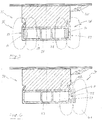
- the Fig. 1 shows a sliding contact device 10 of a contact unit according to the prior art, not shown in detail here, in a cross-sectional view, comprising a sliding strip carrier device 11 and a sliding strip 12 which is arranged and fastened on a support profile 13 of the sliding strip carrier device 11.
- a line 14 while a vehicle (not shown here) is traveling, an air flow 15 flows around the sliding contact device 10, which swirls on a longitudinal side 16 of the sliding contact device 10.
- An arc 18 is formed between a contact wire 17, which runs transversely to the sliding contact device 10 and is in contact with it, and the support profile 13.
- the arc 18 on the support profile 13 detaches a material from the support profile 13 and heats it up at certain points.
- the Fig. 2 shows an embodiment of a sliding contact device 19, which is arranged here on a positioning device, not shown in detail, for positioning the sliding contact device 19 on a contact wire 20 and together with this forms a contact unit.
- the sliding contact device 19 comprises a sliding strip support device 21 and a sliding strip 22 arranged thereon.
- the sliding strip support device 21 is formed from a support profile 23 and comprises a steering device 24 for deflecting or extinguishing arcs 25.
- the sliding strip 22 is made of graphite and is in a trapezoidal receiving groove 26 of the Support profile 23 made of aluminum is used.
- the sliding strip 22 can, among other things, also be connected to the support profile 23 in the receiving groove 26 using an adhesive material (not shown here).
- the support profile 23 is formed with a central hollow chamber 27 and two outer hollow chambers 28.
- the outer hollow chambers 28 border on longitudinal sides 29 of the support profile 23.
- a magnet 30 is inserted in a hollow chamber 28 on the longitudinal side 29, the magnet forming the steering device 24 for the arc 25.
- a magnetic field 32 of the magnet 30 is designed such that a contour 33 of the longitudinal side 29 lies essentially within the magnetic field 32.
- the magnetic field 32 prevents the arc 25 from striking the support profile 23 in that the arc 25 passes through the magnetic field 32 is deflected towards the sliding strip 22.
- An axis of symmetry 34 of the magnetic field 32 runs through the sliding strip 22.
- the Fig. 3 shows an embodiment of a sliding contact device 35, which differs from the sliding contact device from Fig. 2 has a steering device 36 with two magnets 30, which are each arranged in the outer hollow chambers 28 on the longitudinal sides 29.
- This steering device 36 thus enables arcs 25 to be deflected on both longitudinal sides 29 of the support profile 23.
- the Fig. 4 shows an embodiment of a sliding contact device 37, which differs from the sliding contact device from Fig. 2 has a steering device 38, the magnet 39 of which is arranged on the longitudinal side 29 on an outer surface 40 of the support profile 23.
- a magnetic field 41 of the magnet 39 can be shifted closer to an upper edge 42 of the support profile 23 here.
- the Fig. 5 shows an embodiment of a sliding contact device 43, in which, in contrast to the sliding contact device from FIG Fig. 2 the magnet 39 with the axis of symmetry 34 of the magnetic field 32 is arranged in the hollow chamber 28 in such a way that the axis of symmetry runs through the longitudinal side 29. Nevertheless, the upper edge 42 of the support profile 23 is also detected or covered by the magnetic field 32.
- the Fig. 6 shows an embodiment of a sliding contact device 44 with a sliding strip 45, which is attached to a support profile 46 or on its surface 47 with adhesive material, not shown here.
- the sliding contact device 44 here comprises a steering device 48 with two magnets 49, the magnets 49 being fastened to a holding profile 50 of the steering device 48.
- the holding profile 50 is U-shaped, and the magnets 49 are attached to an inner side 51 of legs 52 of the U-shaped holding profile 50.
- the retaining profile 50 is in turn firmly connected to the support profile 46 by means of a screw connection not shown in detail here. With the help of the holding profile 50, the magnets 49 can be positioned so close to an outer edge 53 of the support profile 46 that an arc 25 can be prevented as far as possible in the area of the outer edge 53.
- the Fig. 7 shows an embodiment of a sliding contact device 54, comprising a sliding strip 55 and a support profile 56.
- the support profile 56 here has a central hollow chamber 57 and two outer hollow chambers 58.
- a steering device 59 of the sliding contact device 54 is formed here by a magnet 60 which is inserted into the central hollow chamber 57.
- the magnet 60 is dimensioned to be comparatively large, so that a magnetic field 61 of the magnet 60 covers upper edges 62 of the support profile 56 on both sides.
Landscapes
- Engineering & Computer Science (AREA)
- Power Engineering (AREA)
- Transportation (AREA)
- Mechanical Engineering (AREA)
- Current-Collector Devices For Electrically Propelled Vehicles (AREA)
- Arc-Extinguishing Devices That Are Switches (AREA)
Description
- Die Erfindung betrifft eine Kontakteinheit, insbesondere für eine Stromversorgung von Fahrzeugen über einen Fahrdraht, sowie ein Verfahren zum Lenken von Lichtbögen an einer Kontakteinheit, wobei die Kontakteinheit eine Gleitkontaktvorrichtung umfasst, die eine Schleifleistenträgereinrichtung und eine daran angeordnete Schleifleiste aufweist, wobei die Kontakteinheit eine Lenkeinrichtung für Lichtbögen aufweist, die an der Kontakteinheit angeordnet ist, wobei die Lenkeinrichtung mit einem Magneten ausgebildet ist. Weiter betrifft die Erfindung eine Verwendung eines Magneten zum Lenken oder Löschen von Lichtbögen an einer Kontakteinheit.
- Zur Stromversorgung von schienengebundenen, aber auch nicht schienengebundenen, mit Elektromotoren betriebenen Fahrzeugen werden Kontakteinheiten mit Gleitkontaktvorrichtungen verwendet, die eine Schleifleiste und eine Schleifleistenträgereinrichtung umfassen. Diese Gleitkontaktvorrichtungen werden mit einer Andruckvorrichtung beziehungsweise einer Positioniervorrichtung der Kontakteinheit, wie beispielsweise einem Pantograph oder einer Schwinge, unter Ausbildung einer Andruckkraft gegen einen Fahrstromleiter beziehungsweise Fahrdraht gedrückt. Dadurch wird ein Gleitkontakt ausgebildet, wodurch eine Stromversorgung des Fahrzeugs während einer Fahrt oder auch einem Stopp des Fahrzeugs ermöglicht wird.
- Wesentlich ist dabei, dass auch während eines dynamischen Fahrbetriebs von derartigen Fahrzeugen eine möglichst kontinuierliche Aufrechterhaltung des Gleitkontakts zwischen der Schleifleiste und dem Fahrdraht gewährleistet ist. Es kann jedoch nicht immer ein ununterbrochener Kontakt zwischen der Schleifleiste und dem Fahrdraht sichergestellt werden. Insbesondere bei einer Bildung von Reif, Eis oder sonstigen Anhaftungen am Fahrdraht sind kurzzeitige Ablösungen der Schleifleiste vom Fahrdraht unvermeidlich. Unter anderem bedingt durch diese Ablösungen ist regelmäßig ein elektrischer Überschlag beziehungsweise eine Bildung eines Lichtbogens zwischen dem Fahrdraht und der Schleifleistenträgereinrichtung oder sogar der Positioniervorrichtung zu beobachten, welcher eine Beschädigung der Gleitkontaktvorrichtung oder Bauteilen der Positioniervorrichtung zur Folge haben kann. Auch bereits beim bloßen Kontaktieren des Fahrdrahts mit der Schleifleiste können sich Lichtbögen ausbilden. Eine Ausbildung von Lichtbögen wird auch durch eine erhöhte Luftfeuchtigkeit im Bereich zwischen der Gleitkontaktvorrichtung und dem Fahrdraht begünstigt. Gerade die regelmäßig aus Metall ausgebildete Schleifleistenträgereinrichtung kann durch Lichtbögen stark beschädigt werden, wodurch verkürzte Inspektions- und Austauschintervalle erforderlich werden.
- Die Schleifleistenträgereinrichtung ist häufig aus einem Aluminiumprofil mit einer U-förmigen Aufnahme für die aus einem metallimprägnierten Kohlenstoffmaterial, Hartkohle, Graphit oder einer Metalllegierung bestehende Schleifleiste ausgebildet. Die Schleifleiste kann dabei mit dem Aluminiumprofil verklebt oder auch an der U-förmigen Aufnahme formschlüssig, durch Verbiegen oder Bördeln von Schenkeln der U-förmigen Aufnahme, geklemmt sein. Die Schleifleistenträgereinrichtung kann auch ein sogenannter Hilfsträger sein, der fest an einer Wippe eines Pantographen oder einer Schwinge montiert ist. Bei der Ausbildung eines Lichtbogens zwischen dem Fahrdraht und der Schleifleistenträgereinrichtung kommt es zu einem Wärmeeintrag in die Schleifleistenträgereinrichtung und die Schleifleiste, wobei Material der Schleifleistenträgereinrichtung geschmolzen, verdampft oder abgelöst werden kann. Bei einer wiederholten Ausbildung von Lichtbögen kann die Schleifleistenträgereinrichtung daher stellenweise aufgezehrt und dadurch geschwächt beziehungsweise zerstört werden.
- Aus der
EP 2 746 091 B1 ist eine Gleitkontaktvorrichtung bekannt, die eine Bildung von Lichtbögen zwischen einer Schleifleistenträgereinrichtung und einem Fahrdraht verhindern soll. Insbesondere ist an der Schleifleistenträgereinrichtung ein Strömungskanal ausgebildet, der während einer Fahrt des Fahrzeugs eine gezielte Führung eines Luftstromes derart ermöglicht, dass ein Lichtbogen von der Schleifleistenträgereinrichtung auf die Schleifleiste umgelenkt wird. Nachteilig ist jedoch, dass es während eines Stehens oder auch bei geringen Geschwindigkeiten des Fahrzeugs mangels einer Luftströmung dennoch zu einem Überschlag des Lichtbogens zwischen Fahrdraht und Schleifleistenträgereinrichtung kommt. Gleichwohl ist es auch nicht mehr möglich, mittels einer ausgebildeten Luftströmung einen derartigen Überschlag sicher zu verhindern. Darüber hinaus ist es wünschenswert, auch die Positioniervorrichtung einer Kontakteinheit vor einem Lichtbogenüberschlag zu schützen. - Die
GB 560 769 A - Die
DE 21 30 199 A1 offenbart eine Kontakteinheit für eine Stromversorgung von Fahrzeugen über einen Fahrdraht mit einem Gleitkontakt sowie einer Lichtbogenelektrode. Zwischen dem Fahrdraht und der Lichtbogenelektrode ist ein Lichtbogen ausbildbar, der sich mittels einer Lenkeinrichtung umlenken bzw. stabilisieren lässt. Die Lenkeinrichtung ist hier mit einem Elektromagneten ausgebildet. In Abhängigkeit von einer Fahrgeschwindigkeit des Fahrzeugs kann das Fahrzeug entweder über den Gleitkontakt oder über die Lichtbogenelektrode mit Strom versorgt werden. - Eine weitere Kontakteinheit für eine Stromversorgung von Fahrzeugen über einen Fahrdraht zeigt die
DE 20 02 307 A1 . Insbesondere ist aus diesem Dokument eine Kontakteinheit ersichtlich, welche mit einer Lenkeinrichtung bzw. Blaseinrichtung ausgerüstet ist, mittels der sich ein zwischen einem Fahrdraht und der Kontakteinheit ausgebildeter Lichtbogen umlenken bzw. an eine bestimmte Stelle der Kontakteinheit treiben lässt. Die Lenkeinrichtung ist hier ebenfalls mit einem Elektromagneten ausgebildet. Ähnlich wie bei derDE 21 30 199 A1 liegt auch derDE 20 02 307 A1 die technische Lehre zu Grunde, das Fahrzeug oberhalb einer bestimmten Fahrgeschwindigkeit nicht über einen Gleitkontakt, sondern über einen Lichtbogen mit Strom zu versorgen. - Der vorliegenden Erfindung liegt daher die Aufgabe zugrunde, eine Kontakteinheit sowie ein Verfahren zum Ableiten von Lichtbögen vorzuschlagen, mittels der beziehungsweise dem eine Beschädigung der Kontakteinheit durch Lichtbögen besser verhindert werden kann.
- Diese Aufgabe wird durch eine Kontakteinheit mit den Merkmalen des Anspruchs 1, ein Verfahren mit den Merkmalen des Anspruchs 15 sowie eine Verwendung mit den Merkmalen des Anspruchs 16 gelöst.
- Die erfindungsgemäße Kontakteinheit, insbesondere für eine Stromversorgung von Fahrzeugen über einen Fahrdraht, umfasst eine Gleitkontaktvorrichtung, wobei die Gleitkontaktvorrichtung eine Schleifleistenträgereinrichtung und eine daran angeordnete Schleifleiste aufweist, wobei die Kontakteinheit eine Lenkeinrichtung für Lichtbögen aufweist, die an der Kontakteinheit beziehungsweise benachbart der Kontakteinheit angeordnet ist, wobei die Lenkeinrichtung mit einem Magneten ausgebildet ist, wobei der Magnet an einem Tragprofil der Schleifleistenträgereinrichtung angeordnet ist, wobei mittels des Magneten ein Lichtbogen von dem Tragprofil abweisbar und zu der Schleifleiste hin leitbar oder löschbar ist.
- Eine derartige Kontakteinheit kann aus einer aus einem Kohlenstoffmaterial, Graphit oder einer Metalllegierung bestehenden Schleifleiste an einem Pantographen oder einer Schwinge ausgebildet sein. Durch die Lenkeinrichtung wird es dann möglich, zwischen der Kontakteinheit und dem Fahrdraht überspringende Lichtbögen gezielt so zu lenken, dass Lichtbögen in die Schleifleiste eingeleitet und von der Schleifleistenträgereinrichtung ferngehalten werden. Durch einen Einschlag eines Lichtbogens in die Schleifleiste, wird lediglich die Schleifleiste erwärmt und nicht ein die Schleifleiste halterndes Tragprofil der Schleifleistenträgereinrichtung, welches regelmäßig aus Metall ausgebildet ist. Eine Zerstörung beziehungsweise ein Aufschmelzen dieses Metalls infolge einer Wärmeeinwirkung durch einen Lichtbogeneinschlag kann so verhindert werden. Weiter kann sogar ein Auslöschen eines Lichtbogens erfolgen, sodass der Lichtbogen noch nicht einmal von dem Fahrdraht auf die Gleitkontaktvorrichtung überspringt. Der Magnet kann beliebig ausgebildet oder an der Schleifleistenträgereinrichtung angeordnet sein, wobei alleine wesentlich ist, dass die Ausbildung und Anordnung des Magneten einen Überschlag eines Lichtbogens in ein Tragprofil verhindert und den Lichtbogen in die Schleifleiste umleitet. Die Lenkeinrichtung für Lichtbögen bildet demnach einen im Wesentlichen verschleißfreien Schutz vor Lichtbögen aus. Ein übermäßiger Wärmeeintrag oder ein Verzehr eines Materials des Trägerprofils durch Lichtbögen kann so während eines Stillstands oder einer Fahrt des Fahrzeugs und auch bei einer bloßen Kontaktierung eines Fahrdrahts mit der Gleitkontaktvorrichtung wirkungsvoll verhindert und damit eine Lebensdauer der Gleitkontaktvorrichtung und einer Positioniervorrichtung verlängert werden.
- Erfindungsgemäß ist der Magnet an einem Tragprofil der Schleifleistenträgereinrichtung angeordnet, wobei mittels des Magneten ein Lichtbogen von dem Tragprofil abweisbar und zu der Schleifleiste hin leitbar oder löschbar ist. Der Magnet ist dann in Art eines Ablenkmagneten ausgebildet, der einen Einschlag eines Lichtbogens in das Tragprofil verhindert. Eine Stärke eines Magnetfelds des Magneten muss dabei noch nicht einmal besonders groß sein. So wird auch schon bereits von Magnetfeldern geringer Stärke eine ablenkende Kraft auf Lichtbögen ausgeübt. Das Tragprofil kann beispielsweise aus Aluminium oder einem anderen geeigneten Metall bestehen. Besonders vorteilhaft ist es, wenn das Tragprofil selbst nicht magnetisch oder magnetisierbar ist.
- Besonders vorteilhaft ist es, wenn eine Umlenkung oder ein Auslöschen eines Lichtbogens mittels eines Magnetfeldes des Magneten erfolgt. Der Magnet kann so beschaffen und angeordnet sein, dass insbesondere im Bereich eines Tragprofils der Schleifleistenträgereinrichtung ein Magnetfeld des Magneten ausgebildet beziehungsweise angeordnet ist. Wie sich gezeigt hat, kann ein Magnetfeld einen Lichtbogen umlenken oder auslöschen, sodass der Lichtbogen nicht in das Tragprofil einschlägt.
- Die Lenkeinrichtung kann mit einer Vielzahl von Magneten ausgebildet sein. So wird es dann auch möglich ein Tragprofil der Schleifleistenträgervorrichtung entlang einer Länge innerhalb der regelmäßig ein Fahrdraht quer zur Schleifleiste bewegt wird, vor einem Lichtbogeneinschlag zu schützen.
- Daher kann vorgesehen sein, die Magnete in regelmäßigen Abständen entlang einer Länge der Schleifleistenträgereinrichtung anzuordnen. Wesentlich ist hier, dass Magnetfelder der Magnete dann so ausgebildet sind, dass Abstände zwischen den Magneten von den Magnetfeldern überbrückt werden. Beispielsweise können die Magnetfelder benachbarter Magnete einander überlappen. So kann verhindert werden, dass ein Lichtbogen zwischen zwei Magneten in das Tragprofil einschlägt.
- Der Magnet kann ein Dauermagnet oder auch ein Elektromagnet sein. Mit einem Dauermagnet kann allzeit eine Umlenkung oder Auslöschung von Lichtbögen realisiert werden. Mit einem Elektromagnet kann ein Magnetfeld nach Bedarf ausgebildet werden, beispielsweise, wenn aufgrund bestimmter Witterungsbedingungen ein Lichtbogeneinschlag wahrscheinlich ist. Der Elektromagnet kann einfach mit Strom versorgt werden, da dieser bei elektrisch angetriebenen Fahrzeugen über den Fahrdraht verfügbar ist.
- In einer besonders einfachen Ausführungsform kann der Magnet ein Stabmagnet sein. Der Stabmagnet kann dann entlang einer Länge der Schleifleistenträgervorrichtung angeordnet sein. Stabmagnete sind einfach und kostengünstig in großer Stückzahl verfügbar.
- Der Magnet kann innerhalb und/oder auch außerhalb des Tragprofils an diesem angeordnet sein. Durch eine Anordnung innerhalb des Tragprofils wird der Magnet vor Umwelteinflüssen geschützt. Auch wird eine Außenkontur des Tragprofils nicht verändert, wodurch dann auch keine Änderung von aerodynamischen Eigenschaften der Gleitkontaktvorrichtung erfolgt. Gleichwohl ist es möglich den Magnet an einer Außenfläche des Tragprofils anzuordnen beziehungsweise zu befestigen. Prinzipiell kann so auch eine Nachrüstung einer Gleitkontaktvorrichtung nach dem Stand der Technik mit einem Magnet erfolgen.
- Der Magnet kann auf einer einer Fahrtrichtung abgewandten Längsseite und/oder einer der Fahrtrichtung zugewandten Längsseite des Tragprofils angeordnet sein. Da ein während einer Fahrt des Fahrzeugs an der Gleitkontaktvorrichtung ausgebildeter Luftstrom ebenfalls ein Überschlag eines Lichtbogens beziehungsweise dessen Weg beeinflusst, kann der Magnet zumindest an der der Fahrtrichtung abgewandten Längsseite angeordnet sein. Ist an den gegenüberliegenden Längsseiten jeweils ein Magnet angeordnet, kann darüber hinaus sichergestellt werden, dass bei einer Kontaktierung eines Fahrdrahtes bei einem stehenden Fahrzeug in jedem Fall ein Lichtbogeneinschlag in das Tragprofil verhindert wird. Beispielsweise kann dann jeweils an den Längsseiten, innerhalb oder außerhalb des Tragprofils, eine Reihe von Magneten angeordnet sein. Je nach Art und Stärke des Magnetfelds kann noch ein Magnet oder eine Mehrzahl von Magneten mittig, innerhalb des Tragprofils, angeordnet sein. Wesentlich dabei ist, dass stets eine Außenkontur des Tragprofils noch von einem ausreichend starken Magnetfeld überdeckt ist.
- Eine Symmetrieachse eines Magnetfeldes des Magneten kann durch die Längsseite oder durch die Schleifleiste verlaufen. Das heißt, es ist prinzipiell möglich einen stabförmigen Magneten mit dessen Magnetfeld in Richtung der Schleifleiste oder quer dazu anzuordnen. Gleichwohl ist es möglich diesen Magneten im Wesentlichen parallel zu einem Fahrdraht anzuordnen, sodass die Symmetrieachse des Magnetfelds dann durch die Längsseite verläuft.
- Die Lenkeinrichtung kann ein Halteprofil aufweisen, welches entlang eines Tragprofils der Schleifleistenträgereinrichtung verläuft, und an dem ein Magnet angeordnet beziehungsweise befestigt sein kann, wobei das Halteprofil an dem Tragprofil lösbar befestigt sein kann, wobei mittels des Magneten ein Lichtbogen von dem Tragprofil und dem Halteprofil abweisbar und zu der Schleifleiste hin leitbar oder löschbar sein kann. Bei dieser Ausführungsform einer Lenkeinrichtung muss dann der Magnet nicht direkt an dem Tragprofil befestigt werden. So ist es beispielsweise möglich das Halteprofil zusammen mit dem Magnet zu montieren und dann an dem Tragprofil zu befestigen. Eine Nachrüstung bestehender Gleitkontaktvorrichtungen aus dem Stand der Technik mit einer Lenkeinrichtung kann so wesentlich vereinfacht werden.
- Besonders vorteilhaft ist es, wenn der Magnet angrenzend einer Oberkante des Tragprofils angeordnet ist. Der Magnet liegt an einer äußeren Grenze zwischen Tragprofil und Schleifleiste in einem vergleichsweise kurzen Abstand zu einem Fahrdraht, sodass ein Lichtbogen zunächst das Magnetfeld des Magneten durchdringen müsste, um das Tragprofil zu kontaktieren. Eine Umleitung des Lichtbogens in die Schleifleiste wird durch diese Anordnung an der Oberkante des Tragprofils einfacher möglich.
- Alternativ kann die Lenkeinrichtung ein Halteprofil aufweisen, welches paralell zu einem Tragprofil der Schleifleistenträgereinrichtung verlaufen kann, und an dem dann der Magnet angeordnet ist, wobei das Halteprofil relativ zu dem Tragprofil in einem Abstand zu diesem an der Schleifleistenträgereinrichtung angeordnet sein kann, wobei mittels des Magneten ein Lichtbogen von dem Tragprofil abweisbar und zu der Schleifleiste hin leitbar oder löschbar sein kann. Insbesondere, wenn das Tragprofil und andere Bauteile der Schleifleistenträgereinrichtung aus magnetisierbaren werkstoffen ausgebildet sind, kann ein Magnetfeld des Magneten beeinflusst werden. Daher ist es vorteilhaft, wenn der Magnet in einem geeigneten Abstand zu diesen Bauteilen benachbart dem Tragprofil angeordnet ist. Das Halteprofil kann dann auch so breit ausgebildet sein, das es einen Querschnitt des Tragprofils seitlich überragt.
- Weiter kann die Kontakteinheit eine Positioniervorrichtung zur Halterung und Positionierung der Gleitkontaktvorrichtung an einem Fahrdraht umfassen, wobei die Positioniervorrichtung die Lenkeinrichtung aufweisen kann, wobei der Magnet an einem Abschnitt der Positioniervorrichtung angeordnet sein kann, wobei in einer Kontaktposition der Positioniervorrichtung, in der die Schleifleiste den Fahrdraht kontaktiert, der Abschnitt relativ zu dem Fahrdraht den kürzesten Abstand der Positioniervorrichtung zu dem Fahrdraht aufweist, wobei mittels des Magneten ein Lichtbogen von dem Abschnitt abweisbar und zu der Schleifleiste hin leitbar oder löschbar sein kann. Die Lenkeinrichtung kann demnach auch an der Positioniervorrichtung angeordnet sein und einen Überschlag eines Lichtbogens beziehungsweise dessen Einschlag in die Positioniervorrichtung verhindern. Die Positioniervorrichtung kann ein Pantograph, eine Schwinge oder ähnliches sein. Ein Einschlag eines Lichtbogens in die Positioniervorrichtung kann besonders große Schäden an der Positioniervorrichtung zur Folge haben. Gerade die Abschnitte der Positioniervorrichtung, die einem Fahrdraht dicht angenähert sind, wie beispielsweise ein Scheitelrohr, sind hier besonders gefährdet.
- Um die Kontakteinheit noch sicherer auszubilden, kann die Gleitkontaktvorrichtung und die Positioniervorrichtung jeweils eine Lenkeinrichtung aufweisen.
- Bei dem erfindungsgemäßen Verfahren zum Lenken von Lichtbögen an einer Kontakteinheit, insbesondere für eine Stromversorgung von Fahrzeugen über einen Fahrdraht, wird eine Schleifleistenträgereinrichtung mit einer darin angeordneten Schleifleiste einer Gleitkontaktvorrichtung der Kontakteinheit mit einem Fahrdraht mittels einer Positioniervorrichtung der Kontakteinheit kontaktiert, wobei ein Lichtbogen zwischen dem Fahrdraht und der Schleifleiste ausgebildet wird, wobei der Lichtbogen mittels einer mit einem Magneten ausgebildeten Lenkeinrichtung der Kontakteinheit ausgelöscht oder zu der Schleifleiste hin geleitet wird und die Schleifleiste kontaktiert, wobei der Magnet an einem Tragprofil der Schleifleistenträgereinrichtung angeordnet wird, wobei mittels des Magneten der Lichtbogen von dem Tragprofil abgewiesen und zu der Schleifleiste hin geleitet oder gelöscht wird.
- Unter einem Auslöschen des Lichtbogens wird hier verstanden, dass der Lichtbogen gar nicht erst entsteht oder zumindest teilweise bei einem Überschlag abgeschwächt wird. Die Positioniervorrichtung dient zur Halterung und Positionierung der Gleitkontaktvorrichtung, sodass mittels der Positioniervorrichtung die Schleifleiste an den Fahrdraht herangeführt und mit diesem kontaktiert werden kann. Der Lichtbogen zwischen der Schleifleiste und dem Fahrdraht kann vor oder während einer Kontaktierung ausgebildet werden. Das Fahrzeug kann sich dabei in Bewegung befinden oder auch auf einer Fahrstrecke unbewegt stehen. Wesentlich ist, dass ein Lichtbogen alleine zwischen dem Fahrdraht und der Schleifleiste ausgebildet wird, wenn es zu einer Entstehung eines Lichtbogens kommt. Die Lenkeinrichtung beziehungsweise der die Lenkeinrichtung ausbildende Magnet stellt hier sicher, dass der Lichtbogen keine anderen Bauteile der Gleitkontaktvorrichtung oder der Positioniervorrichtung erreicht beziehungsweise in diese einschlägt. Zu weiteren Vorteilen des erfindungsgemäßen Verfahrens wird auf die Vorteilsbeschreibung der erfindungsgemäßen Kontakteinheit verwiesen.
- Weitere vorteilhafte Ausführungsformen des Verfahrens ergeben sich aus den Merkmalsbeschreibungen der auf den Vorrichtungsanspruch 1 rückbezogenen Unteransprüche.
- Bei der erfindungsgemäßen Verwendung eines Magneten zum Lenken oder Löschen von Lichtbögen an einer Kontakteinheit, insbesondere für eine Stromversorgung von Fahrzeugen über einen Fahrdraht, umfasst die Kontakteinheit eine Gleitkontaktvorrichtung mit einer Schleifleistenträgereinrichtung und einer daran angeordneten Schleifleiste sowie eine Positioniervorrichtung zur Halterung und Positionierung der Gleitkontaktvorrichtung, wobei der Magnet eine Lenkeinrichtung für Lichtbögen ausbildet und an der Kontakteinheit angeordnet ist, wobei der Magnet an einem Tragprofil der Schleifleistenträgereinrichtung angeordnet ist, wobei mittels des Magneten ein Lichtbogen von dem Tragprofil abweisbar und zu der Schleifleiste hin leitbar oder löschbar ist. Zu den Vorteilen der erfindungsgemäßen Verwendung eines Magneten wird auf die Vorteilsbeschreibung der erfindungsgemäßen Vorrichtung und des erfindungsgemäßen Verfahrens verwiesen.
- Weitere Ausführungsformen einer Verwendung ergeben sich aus den Merkmalsbeschreibungen der auf den Vorrichtungsanspruch 1 rückbezogenen Unteransprüche.
- Im Folgenden wird die Erfindung unter Bezugnahme auf die beigefügten Zeichnungen näher erläutert.
- Es zeigen:
- Fig. 1
- eine Gleitkontaktvorrichtung nach dem Stand der Technik in einer Querschnittansicht;
- Fig. 2
- eine erste Ausführungsform einer Gleitkontaktvorrichtung in einer Querschnittansicht;
- Fig. 3
- eine zweite Ausführungsform einer Gleitkontaktvorrichtung in einer Querschnittansicht;
- Fig. 4
- eine dritte Ausführungsform einer Gleitkontaktvorrichtung in einer Querschnittansicht;
- Fig. 5
- eine vierte Ausführungsform einer Gleitkontaktvorrichtung in einer Querschnittansicht;
- Fig. 6
- eine fünfte Ausführungsform einer Gleitkontaktvorrichtung in einer Querschnittansicht;
- Fig. 7
- eine sechste Ausführungsform einer Gleitkontaktvorrichtung in einer Querschnittansicht.
- Die
Fig. 1 zeigt eine Gleitkontaktvorrichtung 10 einer hier nicht näher dargestellten Kontakteinheit nach dem Stand der Technik in einer Querschnittansicht, umfassend eine Schleifleistenträgereinrichtung 11 und eine Schleifleiste 12, die auf einem Tragprofil 13 der Schleifleistenträgereinrichtung 11 angeordnet und befestigt ist. Wie hier mit einer Linie 14 angedeutet, wird während einer Fahrt eines hier nicht dargestellten Fahrzeugs die Gleitkontaktvorrichtung 10 von einer Luftströmung 15 umströmt, die an einer Längsseite 16 der Gleitkontaktvorrichtung 10 verwirbelt. Zwischen einem Fahrdraht 17, der quer zu der Gleitkontaktvorrichtung 10 verläuft und mit dieser kontaktiert ist, und dem Tragprofil 13 ist ein Lichtbogen 18 ausgebildet. Durch den Lichtbogen 18 an dem Tragprofil 13 kommt es zu einer Ablösung eines Materials des Tragprofils 13 sowie zu einer punktuellen Erwärmung desselben. - Die
Fig. 2 zeigt eine Ausführungsform einer Gleitkontaktvorrichtung 19, die hier an einer nicht näher dargestellten Positioniervorrichtung zur Positionierung der Gleitkontaktvorrichtung 19 an einem Fahrdraht 20 angeordnet ist und zusammen mit dieser eine Kontakteinheit ausbildet. Die Gleitkontaktvorrichtung 19 umfasst eine Schleifleistenträgereinrichtung 21 und eine daran angeordnete Schleifleiste 22. Die Schleifleistenträgereinrichtung 21 ist aus einem Tragprofil 23 ausgebildet und umfasst eine Lenkeinrichtung 24 zum Umlenken oder Auslöschen von Lichtbögen 25. Die Schleifleiste 22 besteht aus Graphit und ist in eine trapezförmige Aufnahmenut 26 des Tragprofils 23 aus Aluminium eingesetzt. Die Schleifleiste 22 kann unter anderem auch mit einem hier nicht dargestellten Klebermaterial in der Aufnahmenut 26 mit dem Tragprofil 23 verbunden sein. Das Tragprofil 23 ist mit einer mittleren Hohlkammer 27 und zwei äußeren Hohlkammern 28 ausgebildet. Die äußeren Hohlkammern 28 grenzen an Längsseiten 29 des Tragprofils 23. In einer Hohlkammer 28 ist ein Magnet 30 an der Längsseite 29 eingesetzt, wobei der Magnet die Lenkeinrichtung 24 für den Lichtbogen 25 ausbildet. Insbesondere ist ein Magnetfeld 32 des Magneten 30 so ausgebildet, dass eine Kontur 33 der Längsseite 29 im Wesentlichen innerhalb des Magnetfelds 32 liegt. Das Magnetfeld 32 verhindert einen Einschlag des Lichtbogens 25 in das Tragprofil 23 dadurch, dass der Lichtbogen 25 durch das Magnetfeld 32 zu der Schleifleiste 22 hin umgelenkt wird. Eine Symmetrieachse 34 des Magnetfeldes 32 verläuft dabei durch die Schleifleiste 22. - Die
Fig. 3 zeigt eine Ausführungsform einer Gleitkontaktvorrichtung 35, die im Unterschied zu der Gleitkontaktvorrichtung ausFig. 2 eine Lenkeinrichtung 36 mit zwei Magneten 30 aufweist, die jeweils in den äußeren Hohlkammern 28 an den Längsseiten 29 angeordnet sind. Diese Lenkeinrichtung 36 ermöglicht somit ein Umlenken von Lichtbögen 25 an beiden Längsseiten 29 des Tragprofils 23. - Die
Fig. 4 zeigt eine Ausführungsform einer Gleitkontaktvorrichtung 37, die im Unterschied zu der Gleitkontaktvorrichtung ausFig. 2 eine Lenkeinrichtung 38 aufweist, deren Magnet 39 an der Längsseite 29 an einer Außenfläche 40 des Tragprofils 23 angeordnet ist. Ein Magnetfeld 41 des Magneten 39 kann hier dichter an eine Oberkante 42 des Tragprofils 23 verlagert werden. - Die
Fig. 5 zeigt eine Ausführungsform einer Gleitkontaktvorrichtung 43, bei der im Unterschied zu der Gleitkontaktvorrichtung ausFig. 2 der Magnet 39 mit der Symmetrieachse 34 des Magnetfeldes 32 so in der Hohlkammer 28 angeordnet ist, dass die Symmetrieachse durch die Längsseite 29 verläuft. Gleichwohl wird von dem Magnetfeld 32 die Oberkante 42 des Tragprofils 23 mit erfasst beziehungsweise überdeckt. - Die
Fig. 6 zeigt eine Ausführungsform einer Gleitkontaktvorrichtung 44 mit einer Schleifleiste 45, welche auf einem Tragprofil 46 beziehungsweise auf dessen Oberfläche 47 mit hier nicht dargestellten Klebermaterial befestigt ist. Die Gleitkontaktvorrichtung 44 umfasst hier eine Lenkeinrichtung 48 mit zwei Magneten 49, wobei die Magnete 49 an einem Halteprofil 50 der Lenkeinrichtung 48 befestigt sind. Das Halteprofil 50 ist U-förmig ausgebildet, und die Magnete 49 sind an einer Innenseite 51 von Schenkeln 52 des U-förmigen Halteprofils 50 befestigt. Das Halteprofil 50 ist seinerseits mit dem Tragprofil 46 mittels einer hier nicht näher dargestellten Verschraubung fest verbunden. Mithilfe des Halteprofils 50 können die Magnete 49 so dicht an einer Außenkante 53 des Tragprofils 46 positioniert werden, dass in dem Bereich der Außenkante 53 ein Einschlag eines Lichtbogens 25 weitestgehend verhindert werden kann. - Die
Fig. 7 zeigt eine Ausführungsform einer Gleitkontaktvorrichtung 54, umfassend eine Schleifleiste 55 und ein Tragprofil 56. Das Tragprofil 56 weist hier eine mittlere Hohlkammer 57 und zwei äußere Hohlkammern 58 auf. Eine Lenkeinrichtung 59 der Gleitkontaktvorrichtung 54 ist hier durch einen Magneten 60 ausgebildet, der in die mittlere Hohlkammer 57 eingesetzt ist. Der Magnet 60 ist vergleichsweise groß bemessen, sodass ein Magnetfeld 61 des Magneten 60 Oberkanten 62 des Tragprofils 56 beiderseits überdeckt.
Claims (16)
- Kontakteinheit, insbesondere für eine Stromversorgung von Fahrzeugen über einen Fahrdraht (20), umfassend eine Gleitkontaktvorrichtung (19, 35, 37, 43, 44, 54), wobei die Gleitkontaktvorrichtung eine Schleifleistenträgereinrichtung (21) und eine daran angeordnete Schleifleiste (22, 45, 55) aufweist,
wobei die Kontakteinheit eine Lenkeinrichtung (24, 36, 38, 48, 59) für Lichtbögen (25) aufweist, die an der Kontakteinheit angeordnet ist, wobei die Lenkeinrichtung mit einem Magneten (30, 39, 49, 60) ausgebildet ist,
dadurch gekennzeichnet,
dass der Magnet an einem Tragprofil (23, 46, 56) der Schleifleistenträgereinrichtung angeordnet ist, wobei mittels des Magneten ein Lichtbogen von dem Tragprofil abweisbar und zu der Schleifleiste hin leitbar oder löschbar ist. - Kontakteinheit nach Anspruch 1,
dadurch gekennzeichnet,
dass eine Umlenkung oder ein Auslöschen eines Lichtbogens (25) mittels eines Magnetfeldes (32, 41, 61) des Magneten (30, 39, 49, 60) erfolgt. - Kontakteinheit nach Anspruch 1 oder 2
dadurch gekennzeichnet,
dass die Lenkeinrichtung (24, 36, 38, 48, 59) mit einer Vielzahl von Magneten (30, 39, 49, 60) ausgebildet ist. - Kontakteinheit nach Anspruch 3,
dadurch gekennzeichnet,
dass die Magnete (30, 39, 49, 60) in regelmäßigen Abständen entlang einer Länge der Schleifleistenträgereinrichtung (21) angeordnet sind. - Kontakteinheit nach einem der vorangehenden Ansprüche,
dadurch gekennzeichnet,
dass der Magnet (30, 39, 49, 60) ein Dauermagnet oder ein Elektromagnet ist. - Kontakteinheit nach einem der vorangehenden Ansprüche,
dadurch gekennzeichnet,
dass der Magnet (30, 39, 49, 60) ein Stabmagnet ist. - Kontakteinheit nach einem der vorangehenden Ansprüche,
dadurch gekennzeichnet,
dass der Magnet (30, 39, 49, 60) innerhalb und/oder außerhalb des Tragprofils (23, 46, 56) an diesem angeordnet ist. - Kontakteinheit nach einem der vorangehenden Ansprüche,
dadurch gekennzeichnet,
dass der Magnet (30, 39, 49, 60) auf einer einer Fahrtrichtung abgewandten Längsseite (29) und/oder einer der Fahrtrichtung zugewandten Längsseite des Tragprofils (23, 46, 56) angeordnet ist. - Kontakteinheit nach einem der vorangehenden Ansprüche,
dadurch gekennzeichnet,
dass eine Symmetrieachse (34) eines Magnetfeldes (32, 41, 61) des Magneten (30, 39, 49, 60) durch die Längsseite (29) oder durch die Schleifleiste (22, 45, 55) verläuft. - Kontakteinheit nach einem der Ansprüche 1 bis 6,
dadurch gekennzeichnet,
dass die Lenkeinrichtung (48) ein Halteprofil (50) aufweist, welches entlang eines Tragprofils (46) der Schleifleistenträgereinrichtung verläuft, und an dem der Magnet (49) angeordnet ist, wobei das Halteprofil an dem Tragprofil lösbar befestigt ist, wobei mittels des Magneten ein Lichtbogen (25) von dem Tragprofil und dem Halteprofil abweisbar und zu der Schleifleiste (45) hin leitbar oder löschbar ist. - Kontakteinheit nach einem der vorangehenden Ansprüche,
dadurch gekennzeichnet,
dass der Magnet (30, 39, 49, 60) angrenzend einer Oberkante (42, 62) des Tragprofils (23, 46, 56) angeordnet ist. - Kontakteinheit nach einem der Ansprüche 1 bis 6,
dadurch gekennzeichnet,
dass die Lenkeinrichtung ein Halteprofil aufweist, welches parallel zu einem Tragprofil (23, 46, 56) der Schleifleistenträgereinrichtung (21) verläuft, und an dem der Magnet (30, 39, 49, 60) angeordnet ist, wobei das Halteprofil relativ zu dem Tragprofil in einem Abstand zu diesem an der Schleifleistenträgereinrichtung angeordnet ist, wobei mittels des Magneten ein Lichtbogen (25) von dem Tragprofil abweisbar und zu der Schleifleiste (22, 45, 55) hin leitbar oder löschbar ist. - Kontakteinheit nach einem der Ansprüche 1 bis 6,
dadurch gekennzeichnet,
dass die Kontakteinheit eine Positioniervorrichtung zur Halterung und Positionierung der Gleitkontaktvorrichtung (19, 35, 37, 43, 44, 54) an einem Fahrdraht (20) umfasst, wobei die Positioniervorrichtung die Lenkeinrichtung (24, 36, 38, 48, 59) aufweist, wobei der Magnet (30, 39, 49, 60) an einem Abschnitt der Positioniervorrichtung angeordnet ist, wobei in einer Kontaktposition der Positioniervorrichtung, in der die Schleifleiste den Fahrdraht (20) kontaktiert, der Abschnitt relativ zu dem Fahrdraht den kürzesten Abstand der Positioniervorrichtung zu dem Fahrdraht aufweist, wobei mittels des Magneten ein Lichtbogen (25) von dem Abschnitt abweisbar und zu der Schleifleiste hin leitbar oder löschbar ist. - Kontakteinheit nach Anspruch 12 oder 13,
dadurch gekennzeichnet,
dass die Gleitkontaktvorrichtung (19, 35, 37, 43, 44, 54) und die Positioniervorrichtung jeweils eine Lenkeinrichtung (24, 36, 38, 48, 59) aufweisen. - Verfahren zum Lenken von Lichtbögen (25) an einer Kontakteinheit, insbesondere für eine Stromversorgung von Fahrzeugen über einen Fahrdraht (20), wobei eine Schleifleistenträgereinrichtung (21) mit einer daran angeordneten Schleifleiste (22, 45, 55) einer Gleitkontaktvorrichtung (19, 35, 37, 43, 44, 54) der Kontakteinheit mit einem Fahrdraht mittels einer Positioniervorrichtung der Kontakteinheit kontaktiert wird, wobei ein Lichtbogen zwischen dem Fahrdraht und der Schleifleiste ausgebildet wird,
wobei der Lichtbogen mittels einer mit einem Magneten (30, 39, 49, 60) ausgebildeten Lenkeinrichtung (24, 36, 38, 48, 59) der Kontakteinheit ausgelöscht oder zu der Schleifleiste hin geleitet wird und die Schleifleiste kontaktiert,
dadurch gekennzeichnet,
dass der Magnet an einem Tragprofil (23, 46, 56) der Schleifleistenträgereinrichtung angeordnet wird, wobei mittels des Magneten der Lichtbogen von dem Tragprofil abgewiesen und zu der Schleifleiste hin geleitet oder gelöscht wird. - Verwendung eines Magneten (30, 39, 49, 60) zum Lenken oder Löschen von Lichtbögen (25) an einer Kontakteinheit, insbesondere für eine Stromversorgung von Fahrzeugen über einen Fahrdraht (20), wobei die Kontakteinheit eine Gleitkontaktvorrichtung (19, 35, 37, 43, 44, 54) mit einer Schleifleistenträgereinrichtung (21) und eine daran angeordnete Schleifleiste (22, 45, 55) sowie eine Positioniervorrichtung zur Halterung und Positionierung der Gleitkontaktvorrichtung umfasst, wobei der Magnet eine Lenkeinrichtung (24, 36, 38, 48, 59) für Lichtbögen ausbildet und an der Kontakteinheit angeordnet ist,
dadurch gekennzeichnet,
dass der Magnet an einem Tragprofil (23, 46, 56) der Schleifleistenträgereinrichtung angeordnet ist, wobei mittels des Magneten ein Lichtbogen von dem Tragprofil abweisbar und zu der Schleifleiste hin leitbar oder löschbar ist.
Applications Claiming Priority (1)
| Application Number | Priority Date | Filing Date | Title |
|---|---|---|---|
| DE102017223401.6A DE102017223401B4 (de) | 2017-12-20 | 2017-12-20 | Kontakteinheit und Verfahren |
Publications (2)
| Publication Number | Publication Date |
|---|---|
| EP3501877A1 EP3501877A1 (de) | 2019-06-26 |
| EP3501877B1 true EP3501877B1 (de) | 2021-04-07 |
Family
ID=64564595
Family Applications (1)
| Application Number | Title | Priority Date | Filing Date |
|---|---|---|---|
| EP18209361.7A Active EP3501877B1 (de) | 2017-12-20 | 2018-11-30 | Kontakteinheit und verfahren |
Country Status (7)
| Country | Link |
|---|---|
| US (1) | US11532444B2 (de) |
| EP (1) | EP3501877B1 (de) |
| JP (1) | JP6810733B2 (de) |
| CN (1) | CN110001406B (de) |
| DE (1) | DE102017223401B4 (de) |
| ES (1) | ES2880001T3 (de) |
| RU (1) | RU2726530C2 (de) |
Families Citing this family (3)
| Publication number | Priority date | Publication date | Assignee | Title |
|---|---|---|---|---|
| US20230415588A1 (en) * | 2020-11-30 | 2023-12-28 | Schunk Transit Systems Gmbh | Rapid charging system and method for electrically connecting a vehcile to a charging station |
| CN113189524B (zh) * | 2021-04-30 | 2023-01-24 | 国家电网有限公司 | 一种能够带电作业的线缆检测装置 |
| FR3145516A1 (fr) * | 2023-02-02 | 2024-08-09 | SNCF Voyageurs | Dispositif de protection anti-givre d’une bande d’usure d’un pantographe d’un vehicule ferroviaire |
Citations (2)
| Publication number | Priority date | Publication date | Assignee | Title |
|---|---|---|---|---|
| DE2002307A1 (de) * | 1970-01-20 | 1971-07-29 | Erk Adil Prof Dr Ing | Vorrichtung zum UEbertragen von elektrischer Energie von einem gestreckten ortsfesten Leiter auf einen an diesem entlangbewegten Verbraucher |
| DE2130199A1 (de) * | 1971-06-18 | 1973-01-11 | Messerschmitt Boelkow Blohm | Vorrichtung zum uebertragen elektrischer energie |
Family Cites Families (22)
| Publication number | Priority date | Publication date | Assignee | Title |
|---|---|---|---|---|
| GB560769A (en) * | 1942-10-09 | 1944-04-19 | Nathaniel Herbert Thomas | Arc quenching device for use with current collectors |
| JPS586362B2 (ja) | 1977-04-11 | 1983-02-04 | 株式会社日本砿油 | 接触給、集電部材の潤滑 |
| JPS56152179A (en) * | 1980-04-24 | 1981-11-25 | Mitsubishi Heavy Ind Ltd | Current collector |
| SU988597A1 (ru) | 1981-08-31 | 1983-01-15 | Всесоюзный Научно-Исследовательский,Проектно-Конструкторский И Технологический Институт Электровозостроения | Устройство дл энергоснабжени транспортного средства |
| JPH0787642B2 (ja) | 1988-08-30 | 1995-09-20 | 帝国カーボン工業株式会社 | 高速電気車用軽量複合耐摩摺動集電板 |
| JPH0485529U (de) * | 1990-11-29 | 1992-07-24 | ||
| JPH0568303A (ja) * | 1991-09-09 | 1993-03-19 | Railway Technical Res Inst | 吸引式集電装置 |
| JPH08205308A (ja) | 1995-01-27 | 1996-08-09 | Hitachi Ltd | 車両用集電装置 |
| JPH0942850A (ja) | 1995-07-28 | 1997-02-14 | Ishikawajima Harima Heavy Ind Co Ltd | 直流アーク炉 |
| RU27808U1 (ru) * | 2002-10-22 | 2003-02-20 | Берент Валентин Янович | Токоприемник электроподвижного состава (варианты) |
| DE102004035951C5 (de) * | 2004-07-23 | 2012-11-29 | Bombardier Transportation Gmbh | Elektronmagnetisch betätigbarer Schalter |
| FR2916571B1 (fr) * | 2007-05-22 | 2009-09-11 | Schneider Electric Ind Sas | Chambre de coupure et disjoncteur equipe d'une telle chambre de coupure |
| CN102737795B (zh) | 2011-04-12 | 2014-04-16 | 王巨丰 | 10~35kV架空输电线路约束空间喷射气体灭弧防雷间隙装置 |
| EP2551867A1 (de) * | 2011-07-28 | 2013-01-30 | Eaton Industries GmbH | Schütz für Gleichstrombetrieb |
| DE102011080887A1 (de) * | 2011-08-12 | 2013-02-14 | Siemens Aktiengesellschaft | System zum Betrieb eines elektrischen Triebfahrzeugs |
| FR2981786B1 (fr) | 2011-10-21 | 2013-11-22 | Abb France | Procede de coupure d'un arc electrique, procede et dispositif de protection d'une installation contre les surtensions |
| EP2600367A1 (de) * | 2011-11-29 | 2013-06-05 | Eaton Industries GmbH | Schaltgerät für Gleichstromanwendungen |
| DE102012224254A1 (de) | 2012-12-21 | 2014-06-26 | Hoffmann & Co. Elektrokohle Ag | Gleitkontaktvorrichtung |
| TWI523773B (zh) | 2013-01-18 | 2016-03-01 | 國立臺灣科技大學 | 電氣列車的集電設備及其集電方法 |
| FR3026064B1 (fr) | 2014-09-19 | 2016-11-11 | Soc Nat Des Chemins De Fer Francais Sncf | Ensemble comportant un pantographe pour vehicule ferroviaire et des moyens de generation de micro-ondes et procede de degivrage |
| CN105291852A (zh) | 2015-12-07 | 2016-02-03 | 上海洲跃生物科技有限公司 | 一种倾斜式直杆受电弓装置 |
| DE102017217638B4 (de) * | 2017-10-04 | 2020-07-09 | Schunk Carbon Technology Gmbh | Gleitkontaktvorrichtung und Verfahren |
-
2017
- 2017-12-20 DE DE102017223401.6A patent/DE102017223401B4/de active Active
-
2018
- 2018-11-30 EP EP18209361.7A patent/EP3501877B1/de active Active
- 2018-11-30 ES ES18209361T patent/ES2880001T3/es active Active
- 2018-12-18 US US16/223,199 patent/US11532444B2/en active Active
- 2018-12-20 JP JP2018238484A patent/JP6810733B2/ja active Active
- 2018-12-20 RU RU2018145367A patent/RU2726530C2/ru active
- 2018-12-20 CN CN201811563135.3A patent/CN110001406B/zh active Active
Patent Citations (2)
| Publication number | Priority date | Publication date | Assignee | Title |
|---|---|---|---|---|
| DE2002307A1 (de) * | 1970-01-20 | 1971-07-29 | Erk Adil Prof Dr Ing | Vorrichtung zum UEbertragen von elektrischer Energie von einem gestreckten ortsfesten Leiter auf einen an diesem entlangbewegten Verbraucher |
| DE2130199A1 (de) * | 1971-06-18 | 1973-01-11 | Messerschmitt Boelkow Blohm | Vorrichtung zum uebertragen elektrischer energie |
Also Published As
| Publication number | Publication date |
|---|---|
| CN110001406B (zh) | 2022-12-02 |
| RU2018145367A3 (de) | 2020-06-22 |
| CN110001406A (zh) | 2019-07-12 |
| JP2019146473A (ja) | 2019-08-29 |
| JP6810733B2 (ja) | 2021-01-06 |
| ES2880001T3 (es) | 2021-11-23 |
| RU2018145367A (ru) | 2020-06-22 |
| DE102017223401A1 (de) | 2019-06-27 |
| EP3501877A1 (de) | 2019-06-26 |
| US11532444B2 (en) | 2022-12-20 |
| US20190189369A1 (en) | 2019-06-20 |
| DE102017223401B4 (de) | 2019-10-10 |
| RU2726530C2 (ru) | 2020-07-14 |
Similar Documents
| Publication | Publication Date | Title |
|---|---|---|
| EP3501877B1 (de) | Kontakteinheit und verfahren | |
| EP3084940B1 (de) | Lineares transportsystem und verfahren zum betreiben des linearen transportsystems | |
| EP2964481B2 (de) | Schleifleitung, stromabnehmer und schleifleitungssystem | |
| EP2969637B1 (de) | Schleifleitung, stromabnehmer und schleifleitungssystem mit schlitzhohlleiter zur aufnahme einer antenne | |
| EP2496770B1 (de) | Randsteinabweiser für einen schneepflug | |
| EP3691928B1 (de) | Gleitkontaktvorrichtung und verfahren | |
| EP2698272B1 (de) | Stromschienenauflauf | |
| EP0734110A1 (de) | Drahtloses Energie-Übertragungssystem | |
| EP0592819A1 (de) | Streckentrenner mit Isolierkufen | |
| DE102004020886B4 (de) | Schleifvorrichtung für absenkbare Stromabnehmer | |
| EP3947016B1 (de) | Stromabnehmer für ein schienenfahrzeug | |
| EP2613962B1 (de) | Streckentrenneinrichtung für eine stromschienen-oberleitungsanlage | |
| EP3703971B1 (de) | Oberleitungsanordnung und verfahren zur montage einer oberleitungsanordnung | |
| EP3478550B1 (de) | Aussenverkleidungselement für ein fahrzeug | |
| DE19730375A1 (de) | Verfahren und Vorrichtung zum Auslenken einer Walzader | |
| DE102019116443A1 (de) | Stromschine für eine Strassenfahrbahn | |
| DE202004006776U1 (de) | Schleifvorrichtung für absenkbare Stromabnehmer | |
| WO2025131374A1 (de) | Befestigungsvorrichtung und fahrleitungsanlage mit befestigungsvorrichtung | |
| EP1753636A1 (de) | Schleifvorrichtung für absenkbare stromabnehmer | |
| EP3269583B1 (de) | Seitenstromabnehmervorrichtung für ein schienenfahrzeug | |
| DE202014102489U1 (de) | Schleifleitung, Stromabnehmer und Schleifleitungssystem | |
| DE7332783U (de) | Lichtbogenloschkammer fur Strecken trenner | |
| DE202015100623U1 (de) | Stromabnehmer und Schleifleitungssystem | |
| AT8616U1 (de) | Plattenförmiges schermesser | |
| DE2002307A1 (de) | Vorrichtung zum UEbertragen von elektrischer Energie von einem gestreckten ortsfesten Leiter auf einen an diesem entlangbewegten Verbraucher |
Legal Events
| Date | Code | Title | Description |
|---|---|---|---|
| PUAI | Public reference made under article 153(3) epc to a published international application that has entered the european phase |
Free format text: ORIGINAL CODE: 0009012 |
|
| STAA | Information on the status of an ep patent application or granted ep patent |
Free format text: STATUS: THE APPLICATION HAS BEEN PUBLISHED |
|
| AK | Designated contracting states |
Kind code of ref document: A1 Designated state(s): AL AT BE BG CH CY CZ DE DK EE ES FI FR GB GR HR HU IE IS IT LI LT LU LV MC MK MT NL NO PL PT RO RS SE SI SK SM TR |
|
| AX | Request for extension of the european patent |
Extension state: BA ME |
|
| STAA | Information on the status of an ep patent application or granted ep patent |
Free format text: STATUS: REQUEST FOR EXAMINATION WAS MADE |
|
| 17P | Request for examination filed |
Effective date: 20191219 |
|
| RBV | Designated contracting states (corrected) |
Designated state(s): AL AT BE BG CH CY CZ DE DK EE ES FI FR GB GR HR HU IE IS IT LI LT LU LV MC MK MT NL NO PL PT RO RS SE SI SK SM TR |
|
| STAA | Information on the status of an ep patent application or granted ep patent |
Free format text: STATUS: EXAMINATION IS IN PROGRESS |
|
| 17Q | First examination report despatched |
Effective date: 20200424 |
|
| GRAP | Despatch of communication of intention to grant a patent |
Free format text: ORIGINAL CODE: EPIDOSNIGR1 |
|
| STAA | Information on the status of an ep patent application or granted ep patent |
Free format text: STATUS: GRANT OF PATENT IS INTENDED |
|
| INTG | Intention to grant announced |
Effective date: 20201127 |
|
| GRAS | Grant fee paid |
Free format text: ORIGINAL CODE: EPIDOSNIGR3 |
|
| GRAA | (expected) grant |
Free format text: ORIGINAL CODE: 0009210 |
|
| STAA | Information on the status of an ep patent application or granted ep patent |
Free format text: STATUS: THE PATENT HAS BEEN GRANTED |
|
| AK | Designated contracting states |
Kind code of ref document: B1 Designated state(s): AL AT BE BG CH CY CZ DK EE ES FI FR GB GR HR HU IE IS IT LI LT LU LV MC MK MT NL NO PL PT RO RS SE SI SK SM TR |
|
| RBV | Designated contracting states (corrected) |
Designated state(s): AL AT BE BG CH CY CZ DK EE ES FI FR GB GR HR HU IE IS IT LI LT LU LV MC MK MT NL NO PL PT RO RS SE SI SK SM TR |
|
| REG | Reference to a national code |
Ref country code: GB Ref legal event code: FG4D Free format text: NOT ENGLISH Ref country code: DE Ref legal event code: R108 |
|
| REG | Reference to a national code |
Ref country code: CH Ref legal event code: EP Ref country code: AT Ref legal event code: REF Ref document number: 1379261 Country of ref document: AT Kind code of ref document: T Effective date: 20210415 |
|
| REG | Reference to a national code |
Ref country code: IE Ref legal event code: FG4D Free format text: LANGUAGE OF EP DOCUMENT: GERMAN |
|
| REG | Reference to a national code |
Ref country code: NL Ref legal event code: FP |
|
| REG | Reference to a national code |
Ref country code: LT Ref legal event code: MG9D |
|
| PG25 | Lapsed in a contracting state [announced via postgrant information from national office to epo] |
Ref country code: BG Free format text: LAPSE BECAUSE OF FAILURE TO SUBMIT A TRANSLATION OF THE DESCRIPTION OR TO PAY THE FEE WITHIN THE PRESCRIBED TIME-LIMIT Effective date: 20210707 Ref country code: FI Free format text: LAPSE BECAUSE OF FAILURE TO SUBMIT A TRANSLATION OF THE DESCRIPTION OR TO PAY THE FEE WITHIN THE PRESCRIBED TIME-LIMIT Effective date: 20210407 Ref country code: LT Free format text: LAPSE BECAUSE OF FAILURE TO SUBMIT A TRANSLATION OF THE DESCRIPTION OR TO PAY THE FEE WITHIN THE PRESCRIBED TIME-LIMIT Effective date: 20210407 Ref country code: HR Free format text: LAPSE BECAUSE OF FAILURE TO SUBMIT A TRANSLATION OF THE DESCRIPTION OR TO PAY THE FEE WITHIN THE PRESCRIBED TIME-LIMIT Effective date: 20210407 |
|
| REG | Reference to a national code |
Ref country code: ES Ref legal event code: FG2A Ref document number: 2880001 Country of ref document: ES Kind code of ref document: T3 Effective date: 20211123 |
|
| PG25 | Lapsed in a contracting state [announced via postgrant information from national office to epo] |
Ref country code: GR Free format text: LAPSE BECAUSE OF FAILURE TO SUBMIT A TRANSLATION OF THE DESCRIPTION OR TO PAY THE FEE WITHIN THE PRESCRIBED TIME-LIMIT Effective date: 20210708 Ref country code: IS Free format text: LAPSE BECAUSE OF FAILURE TO SUBMIT A TRANSLATION OF THE DESCRIPTION OR TO PAY THE FEE WITHIN THE PRESCRIBED TIME-LIMIT Effective date: 20210807 Ref country code: LV Free format text: LAPSE BECAUSE OF FAILURE TO SUBMIT A TRANSLATION OF THE DESCRIPTION OR TO PAY THE FEE WITHIN THE PRESCRIBED TIME-LIMIT Effective date: 20210407 Ref country code: PT Free format text: LAPSE BECAUSE OF FAILURE TO SUBMIT A TRANSLATION OF THE DESCRIPTION OR TO PAY THE FEE WITHIN THE PRESCRIBED TIME-LIMIT Effective date: 20210809 Ref country code: NO Free format text: LAPSE BECAUSE OF FAILURE TO SUBMIT A TRANSLATION OF THE DESCRIPTION OR TO PAY THE FEE WITHIN THE PRESCRIBED TIME-LIMIT Effective date: 20210707 Ref country code: PL Free format text: LAPSE BECAUSE OF FAILURE TO SUBMIT A TRANSLATION OF THE DESCRIPTION OR TO PAY THE FEE WITHIN THE PRESCRIBED TIME-LIMIT Effective date: 20210407 Ref country code: SE Free format text: LAPSE BECAUSE OF FAILURE TO SUBMIT A TRANSLATION OF THE DESCRIPTION OR TO PAY THE FEE WITHIN THE PRESCRIBED TIME-LIMIT Effective date: 20210407 Ref country code: RS Free format text: LAPSE BECAUSE OF FAILURE TO SUBMIT A TRANSLATION OF THE DESCRIPTION OR TO PAY THE FEE WITHIN THE PRESCRIBED TIME-LIMIT Effective date: 20210407 |
|
| PG25 | Lapsed in a contracting state [announced via postgrant information from national office to epo] |
Ref country code: SK Free format text: LAPSE BECAUSE OF FAILURE TO SUBMIT A TRANSLATION OF THE DESCRIPTION OR TO PAY THE FEE WITHIN THE PRESCRIBED TIME-LIMIT Effective date: 20210407 Ref country code: SM Free format text: LAPSE BECAUSE OF FAILURE TO SUBMIT A TRANSLATION OF THE DESCRIPTION OR TO PAY THE FEE WITHIN THE PRESCRIBED TIME-LIMIT Effective date: 20210407 Ref country code: EE Free format text: LAPSE BECAUSE OF FAILURE TO SUBMIT A TRANSLATION OF THE DESCRIPTION OR TO PAY THE FEE WITHIN THE PRESCRIBED TIME-LIMIT Effective date: 20210407 Ref country code: DK Free format text: LAPSE BECAUSE OF FAILURE TO SUBMIT A TRANSLATION OF THE DESCRIPTION OR TO PAY THE FEE WITHIN THE PRESCRIBED TIME-LIMIT Effective date: 20210407 Ref country code: CZ Free format text: LAPSE BECAUSE OF FAILURE TO SUBMIT A TRANSLATION OF THE DESCRIPTION OR TO PAY THE FEE WITHIN THE PRESCRIBED TIME-LIMIT Effective date: 20210407 Ref country code: RO Free format text: LAPSE BECAUSE OF FAILURE TO SUBMIT A TRANSLATION OF THE DESCRIPTION OR TO PAY THE FEE WITHIN THE PRESCRIBED TIME-LIMIT Effective date: 20210407 |
|
| PLBE | No opposition filed within time limit |
Free format text: ORIGINAL CODE: 0009261 |
|
| STAA | Information on the status of an ep patent application or granted ep patent |
Free format text: STATUS: NO OPPOSITION FILED WITHIN TIME LIMIT |
|
| 26N | No opposition filed |
Effective date: 20220110 |
|
| PG25 | Lapsed in a contracting state [announced via postgrant information from national office to epo] |
Ref country code: IS Free format text: LAPSE BECAUSE OF FAILURE TO SUBMIT A TRANSLATION OF THE DESCRIPTION OR TO PAY THE FEE WITHIN THE PRESCRIBED TIME-LIMIT Effective date: 20210807 Ref country code: AL Free format text: LAPSE BECAUSE OF FAILURE TO SUBMIT A TRANSLATION OF THE DESCRIPTION OR TO PAY THE FEE WITHIN THE PRESCRIBED TIME-LIMIT Effective date: 20210407 |
|
| PG25 | Lapsed in a contracting state [announced via postgrant information from national office to epo] |
Ref country code: MC Free format text: LAPSE BECAUSE OF FAILURE TO SUBMIT A TRANSLATION OF THE DESCRIPTION OR TO PAY THE FEE WITHIN THE PRESCRIBED TIME-LIMIT Effective date: 20210407 |
|
| REG | Reference to a national code |
Ref country code: CH Ref legal event code: PL |
|
| PG25 | Lapsed in a contracting state [announced via postgrant information from national office to epo] |
Ref country code: LU Free format text: LAPSE BECAUSE OF NON-PAYMENT OF DUE FEES Effective date: 20211130 |
|
| PG25 | Lapsed in a contracting state [announced via postgrant information from national office to epo] |
Ref country code: LI Free format text: LAPSE BECAUSE OF NON-PAYMENT OF DUE FEES Effective date: 20211130 Ref country code: CH Free format text: LAPSE BECAUSE OF NON-PAYMENT OF DUE FEES Effective date: 20211130 |
|
| PG25 | Lapsed in a contracting state [announced via postgrant information from national office to epo] |
Ref country code: IE Free format text: LAPSE BECAUSE OF NON-PAYMENT OF DUE FEES Effective date: 20211130 |
|
| P01 | Opt-out of the competence of the unified patent court (upc) registered |
Effective date: 20230524 |
|
| PG25 | Lapsed in a contracting state [announced via postgrant information from national office to epo] |
Ref country code: CY Free format text: LAPSE BECAUSE OF FAILURE TO SUBMIT A TRANSLATION OF THE DESCRIPTION OR TO PAY THE FEE WITHIN THE PRESCRIBED TIME-LIMIT Effective date: 20210407 |
|
| GBPC | Gb: european patent ceased through non-payment of renewal fee |
Effective date: 20221130 |
|
| PG25 | Lapsed in a contracting state [announced via postgrant information from national office to epo] |
Ref country code: HU Free format text: LAPSE BECAUSE OF FAILURE TO SUBMIT A TRANSLATION OF THE DESCRIPTION OR TO PAY THE FEE WITHIN THE PRESCRIBED TIME-LIMIT; INVALID AB INITIO Effective date: 20181130 |
|
| PG25 | Lapsed in a contracting state [announced via postgrant information from national office to epo] |
Ref country code: GB Free format text: LAPSE BECAUSE OF NON-PAYMENT OF DUE FEES Effective date: 20221130 |
|
| PG25 | Lapsed in a contracting state [announced via postgrant information from national office to epo] |
Ref country code: MK Free format text: LAPSE BECAUSE OF FAILURE TO SUBMIT A TRANSLATION OF THE DESCRIPTION OR TO PAY THE FEE WITHIN THE PRESCRIBED TIME-LIMIT Effective date: 20210407 |
|
| PG25 | Lapsed in a contracting state [announced via postgrant information from national office to epo] |
Ref country code: TR Free format text: LAPSE BECAUSE OF FAILURE TO SUBMIT A TRANSLATION OF THE DESCRIPTION OR TO PAY THE FEE WITHIN THE PRESCRIBED TIME-LIMIT Effective date: 20210407 |
|
| PG25 | Lapsed in a contracting state [announced via postgrant information from national office to epo] |
Ref country code: MT Free format text: LAPSE BECAUSE OF FAILURE TO SUBMIT A TRANSLATION OF THE DESCRIPTION OR TO PAY THE FEE WITHIN THE PRESCRIBED TIME-LIMIT Effective date: 20210407 |
|
| REG | Reference to a national code |
Ref country code: AT Ref legal event code: MM01 Ref document number: 1379261 Country of ref document: AT Kind code of ref document: T Effective date: 20231130 |
|
| PG25 | Lapsed in a contracting state [announced via postgrant information from national office to epo] |
Ref country code: AT Free format text: LAPSE BECAUSE OF NON-PAYMENT OF DUE FEES Effective date: 20231130 |
|
| PG25 | Lapsed in a contracting state [announced via postgrant information from national office to epo] |
Ref country code: AT Free format text: LAPSE BECAUSE OF NON-PAYMENT OF DUE FEES Effective date: 20231130 |
|
| PGFP | Annual fee paid to national office [announced via postgrant information from national office to epo] |
Ref country code: NL Payment date: 20251124 Year of fee payment: 8 |
|
| PGFP | Annual fee paid to national office [announced via postgrant information from national office to epo] |
Ref country code: IT Payment date: 20251121 Year of fee payment: 8 |
|
| PGFP | Annual fee paid to national office [announced via postgrant information from national office to epo] |
Ref country code: FR Payment date: 20251124 Year of fee payment: 8 |
|
| PGFP | Annual fee paid to national office [announced via postgrant information from national office to epo] |
Ref country code: BE Payment date: 20251124 Year of fee payment: 8 |
|
| PGFP | Annual fee paid to national office [announced via postgrant information from national office to epo] |
Ref country code: ES Payment date: 20251209 Year of fee payment: 8 |
|
| PGFP | Annual fee paid to national office [announced via postgrant information from national office to epo] |
Ref country code: AT Payment date: 20260410 Year of fee payment: 5 |