EP3503148B1 - Schaltkontakteinheit zur montage an einem falz zwischen einem blendrahmen und einem fenster- oder türflügel - Google Patents
Schaltkontakteinheit zur montage an einem falz zwischen einem blendrahmen und einem fenster- oder türflügel Download PDFInfo
- Publication number
- EP3503148B1 EP3503148B1 EP18214659.7A EP18214659A EP3503148B1 EP 3503148 B1 EP3503148 B1 EP 3503148B1 EP 18214659 A EP18214659 A EP 18214659A EP 3503148 B1 EP3503148 B1 EP 3503148B1
- Authority
- EP
- European Patent Office
- Prior art keywords
- switching
- sash
- contact unit
- switching contact
- window
- Prior art date
- Legal status (The legal status is an assumption and is not a legal conclusion. Google has not performed a legal analysis and makes no representation as to the accuracy of the status listed.)
- Active
Links
Images

Classifications
-
- H—ELECTRICITY
- H01—ELECTRIC ELEMENTS
- H01H—ELECTRIC SWITCHES; RELAYS; SELECTORS; EMERGENCY PROTECTIVE DEVICES
- H01H13/00—Switches having rectilinearly-movable operating part or parts adapted for pushing or pulling in one direction only, e.g. push-button switch
- H01H13/02—Details
- H01H13/12—Movable parts; Contacts mounted thereon
- H01H13/14—Operating parts, e.g. push-button
- H01H13/18—Operating parts, e.g. push-button adapted for actuation at a limit or other predetermined position in the path of a body, the relative movement of switch and body being primarily for a purpose other than the actuation of the switch, e.g. door switch, limit switch, floor-levelling switch of a lift
- H01H13/183—Operating parts, e.g. push-button adapted for actuation at a limit or other predetermined position in the path of a body, the relative movement of switch and body being primarily for a purpose other than the actuation of the switch, e.g. door switch, limit switch, floor-levelling switch of a lift for actuation by moving a closing member, e.g. door, cover
-
- G—PHYSICS
- G08—SIGNALLING
- G08B—SIGNALLING SYSTEMS, e.g. PERSONAL CALLING SYSTEMS; ORDER TELEGRAPHS; ALARM SYSTEMS
- G08B13/00—Burglar, theft or intruder alarms
- G08B13/02—Mechanical actuation
- G08B13/08—Mechanical actuation by opening, e.g. of door, of window, of drawer, of shutter, of curtain, of blind
-
- H—ELECTRICITY
- H01—ELECTRIC ELEMENTS
- H01H—ELECTRIC SWITCHES; RELAYS; SELECTORS; EMERGENCY PROTECTIVE DEVICES
- H01H13/00—Switches having rectilinearly-movable operating part or parts adapted for pushing or pulling in one direction only, e.g. push-button switch
- H01H13/02—Details
- H01H13/12—Movable parts; Contacts mounted thereon
- H01H13/14—Operating parts, e.g. push-button
- H01H13/18—Operating parts, e.g. push-button adapted for actuation at a limit or other predetermined position in the path of a body, the relative movement of switch and body being primarily for a purpose other than the actuation of the switch, e.g. door switch, limit switch, floor-levelling switch of a lift
- H01H13/186—Operating parts, e.g. push-button adapted for actuation at a limit or other predetermined position in the path of a body, the relative movement of switch and body being primarily for a purpose other than the actuation of the switch, e.g. door switch, limit switch, floor-levelling switch of a lift wherein the pushbutton is rectilinearly actuated by a lever pivoting on the housing of the switch
-
- H—ELECTRICITY
- H01—ELECTRIC ELEMENTS
- H01H—ELECTRIC SWITCHES; RELAYS; SELECTORS; EMERGENCY PROTECTIVE DEVICES
- H01H3/00—Mechanisms for operating contacts
- H01H3/02—Operating parts, i.e. for operating driving mechanism by a mechanical force external to the switch
- H01H3/16—Operating parts, i.e. for operating driving mechanism by a mechanical force external to the switch adapted for actuation at a limit or other predetermined position in the path of a body, the relative movement of switch and body being primarily for a purpose other than the actuation of the switch, e.g. for a door switch, a limit switch, a floor-levelling switch of a lift
- H01H3/161—Operating parts, i.e. for operating driving mechanism by a mechanical force external to the switch adapted for actuation at a limit or other predetermined position in the path of a body, the relative movement of switch and body being primarily for a purpose other than the actuation of the switch, e.g. for a door switch, a limit switch, a floor-levelling switch of a lift for actuation by moving a closing member, e.g. door, cover or lid
-
- H—ELECTRICITY
- H01—ELECTRIC ELEMENTS
- H01H—ELECTRIC SWITCHES; RELAYS; SELECTORS; EMERGENCY PROTECTIVE DEVICES
- H01H3/00—Mechanisms for operating contacts
- H01H3/02—Operating parts, i.e. for operating driving mechanism by a mechanical force external to the switch
- H01H3/16—Operating parts, i.e. for operating driving mechanism by a mechanical force external to the switch adapted for actuation at a limit or other predetermined position in the path of a body, the relative movement of switch and body being primarily for a purpose other than the actuation of the switch, e.g. for a door switch, a limit switch, a floor-levelling switch of a lift
- H01H3/161—Operating parts, i.e. for operating driving mechanism by a mechanical force external to the switch adapted for actuation at a limit or other predetermined position in the path of a body, the relative movement of switch and body being primarily for a purpose other than the actuation of the switch, e.g. for a door switch, a limit switch, a floor-levelling switch of a lift for actuation by moving a closing member, e.g. door, cover or lid
- H01H2003/165—Operating parts, i.e. for operating driving mechanism by a mechanical force external to the switch adapted for actuation at a limit or other predetermined position in the path of a body, the relative movement of switch and body being primarily for a purpose other than the actuation of the switch, e.g. for a door switch, a limit switch, a floor-levelling switch of a lift for actuation by moving a closing member, e.g. door, cover or lid associated with an edge of the closing member
Definitions
- the invention relates to a switching contact unit for mounting on a rebate between a frame and a window or door sash, with the features of the preamble of claim 1.
- Switching contacts are simple sensors with which the opening or closing status of a window or door leaf can be recorded. For example, they are integrated in burglar alarm systems to indicate windows and doors that are not closed before arming and to signal the opening of a window or door leaf after arming. Such switching contacts are often formed by reed relays attached to the frame, which are operated by permanent magnets attached to the sash. Such switching contacts, such as those for example EP 7757 339 B1 shows, can be attached concealed due to their small design and cannot be felt from the outside, so they meet high security standards. The filigree training, however, requires individual and time-consuming assembly, with assembly being required both on the frame and on the sash.
- Switching contacts are also required for building automation in order to detect the opening status of windows and doors and to control ventilation or shading as a function of this.
- concealed installation and sabotage security are less important than quick and easy installation without time-consuming reworking on the window or door, as well as high operational reliability.
- Another special feature is that in intrusion alarm systems, the opening of the sash opposite the frame only needs to be recognized somehow, so that the gap and the exact switching point are not important.
- the switching contact unit should, if possible, detect whether the sash is in sealing contact with the frame, so that a precise switching point is required for the position of the sash in relation to the frame.
- stronger wind loads that push the sash away from the frame must not cause the sensor to be triggered incorrectly.
- the DE-PS 1703002 suggests a window with a microswitch.
- Microswitches are in themselves characterized by short switching paths and precise switching points.
- the direct actuation of the actuating element of the microswitch via an edge of the window sash is difficult to adjust, especially with regard to wind loads and the settlement behavior of seals.
- a generic switch contact unit is in CN 203397940 U shown.
- the plunger of the microswitch is exactly perpendicular to the switch contact bolt and the conical shoulder on it, via which the plunger is to be actuated, is short and is set at a steep angle. This means that considerable transverse forces act on the microswitch plunger.
- WO 2005/052970 A1 discloses a switch contact unit according to the preamble of claim 1.
- the object of the invention is therefore to provide a switching contact unit for mounting on a rebate between a frame and a window or door sash, which is easy to install, with which a sealed closed position of the sash can be reliably detected and which is operated by gently actuating the microswitch should enable a long service life.
- the invention is defined in the claims and is described below in such a way that the switch contact unit is intended for mounting on the frame. This is the simplest and therefore the most common method of attachment, because cable connections then do not have to be routed from the movable sash to the frame. However, beyond the narrower wording, the invention is also intended to include the arrangement of the switch contact unit on the wing.
- the actuating element of the microswitch element is not in direct contact with an edge or surface on the sash, but that a switch contact bolt is movably mounted approximately at right angles to the longitudinal extension of the frame profile and that the microswitch scans the circumference of a switch contact bolt.
- the switch contact pin is pressed against the sash by a spring element and is moved when the sash is moved away from the frame.
- a switching section of the switching contact bolt reaches the actuating element of the microswitch element, which can be an axially displaceable switching plunger or a switching tongue which is pivotable about an axis.
- an electrical contact is opened or closed.
- a conical transition is formed between the base section of the switch contact bolt and the switch section.
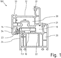
- Figure 1 shows a conventional configuration of a window 100 with a frame 20 and a sash 30 movably mounted thereon.
- the frame 20 and the sash 30 are formed from plastic hollow profiles.
- the frame 20 has on the inner circumference a protruding profile section 21 for the contact of the wing 30 and an adjacent fold 22.
- the wing 30 has on the inner circumference a protruding profile section 31 for the contact of a pane or a filling and an adjacent fold 32, also a wing overlap 33 on Outer circumference.
- a free cross-sectional area 40 is formed in the area of the folds 22, 32.
- a distance is established between the flap 33 and the visible surface 24 which corresponds to the width of a compressed seal 34 arranged there when the window is in the tightly closed state with respect to the Frame is located.
- the end of a switch contact pin 14 protrudes from the switch contact unit 10 by this length.
- the switch contact unit 10 should be positioned directly where there is a fixed mechanical connection between the frame 20 and sash 30 in the closed state, for example in the area of the hinges or where the pins on the sash engage in receptacles in the frame. At these points, the mentioned distance between sash 30 and frame 20 is almost constant due to the mechanical connection, even when exposed to heat or wind, so that there is no risk of switching contact unit 10 switching over when the window is closed and generating an incorrect signal.
- the glazing bead groove 23, which is usually present in the case of frame profiles as the inside delimitation of the fold 22, is used according to the invention for the precise positioning of the switching contact unit 10.
- it has a hook profile web 11.1 on the underside, which can be snapped into the glass bead groove 23.
- the seat of the switching contact is thus secured and precisely positioned.
- the switching contact unit 10 can still be moved laterally with the hooked profile web 11.1 until it is finally fastened.
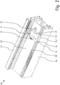
- FIG. 2 shows a section of the frame 20 with an attached switch contact unit 10 in a perspective view.
- the switch contact unit has a base housing 11. An opening therein is closed with a cover 17. Fastening tabs 12 formed on two sides rest on the fold 22 and allow simple screwing as soon as the switch contact unit 10 is correctly positioned. An end face 11.2 of the base housing is flush with the inner visible surface 24.
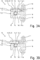
- Figure 3A shows a cut switch contact unit 10. It comprises a base housing 11, a spring element 13, a switch contact bolt 14 and an electrical microswitch element 15.
- a bolt guide recess 11.3 for the switch contact pin 14 and a recess 11.4 for the microswitch element 15.
- the recess 11.4 is open at the top and is secured by the cover element 17 ( Fig. 1 , 2 ) locked.
- the switch contact pin 14 extends from its end 14.1 protruding from the base housing 11 first in a cylindrical base section 14.2 and then expands in the area of the position of the microswitch element 15 via a cone section 14.4 to a switch section 14.4 with an enlarged diameter.
- the central axis of the switching contact pin 14 also indicates the direction of displacement V.
- the microswitch element 15 has a pivotable switching tongue 16 as an actuating element and is fastened in the recess 11. 4 of the basic housing 11.
- the line B indicates the direction of actuation in which the actuation element 16 must be moved in order to change the electrical switching state.
- the lines V and B enclose an angle of about 80 °, the angle in particular should be between 60 ° and 85 °, provided that the switching point of the microswitch element 15 is reached when the switching tongue is aligned perpendicular to the direction of actuation B. .
- the initial inclination of the switch tongue is more important than the alignment of the housing. The inclination improves the switching behavior and the switching reliability, which can be explained as follows:
- the actuating element is designed as a switch tongue 16 and is pivotably mounted at a hinge point 16.1 on the right of the housing of the microswitch element 15, i.e. on the side on which the switch contact pin 14 has its actuating section. Some play must remain between the switching section 14.4 and a hinge point 16.1 of the switching tongue 16 serving as an actuating element so that the switching contact unit 14 is not blocked there. The switching point is approximately reached when the Switching tongue 16 is at right angles to the direction of actuation or parallel to the upper edge of the microswitch element 15.
- the switch tongue 16 would extend parallel to the switch section 14.4 on the switch contact pin 14 and the switching point would theoretically always be reached exactly. Due to wear and tear or changes in the ambient temperature, however, an unsafe switching state could arise because the switching section 14.4 could then slide along the actuating element 16 without being pushed in far enough and the switching point would no longer be safely reached.
- the microswitch element 14 Since the microswitch element 14 is now inclined slightly against the direction of displacement V, a kind of run-up slope is created between the switching tongue 16 and the outer circumference of the switching section 14.4, that is, the resilient switching tongue 16 is inevitably pushed down more and more with increasing displacement of the switching contact pin 14, so that the switching state is reached in any case at any point along the switching path.
- the actual axial position of the switching contact pin 14, at which the electrical switching is effected, can be a few millimeters further forwards or backwards due to tolerances; the only important thing is that it is safely reached in any case.
- Figure 3A shows a position of the switching contact pin 14, which is only reached if it is pushed back manually until its end face 14.1 is flush with a side surface 11.2 of the basic housing 11
- Figure 3B shows the initial position in the closed state of the window 100 or the door during normal use.
- the length of the protruding part of the base section 14.2 of the switching contact pin 14 corresponds to the width of the seal 34, compressed when the window is closed, between the flap 33 on the sash 30 and the inner visible surface 24 on the frame 20 (FIG. 1).
- the switch contact pin 14 When the wing now opens, the switch contact pin 14 is pushed to the left by the spring element 13 beyond the side surface 11.2, as in FIG Figure 3B shown.
- the actuating element 16 now touches the conical section 14.3 and thus comes into a position relative to the housing of the microswitch element 15 which almost corresponds to the switch position.
- the pressure point of the switching element inside the microswitch element 15 has been reached, but not yet overcome. Any further axial movement of the switch contact pin 14 triggers the switching process.
- the switch contact unit 10 can be used to detect whether a wing 30 is only resting - then the seal 34 is not compressed and the switch contact unit 10 signals an open state - or is firmly locked.
Landscapes
- Physics & Mathematics (AREA)
- General Physics & Mathematics (AREA)
- Engineering & Computer Science (AREA)
- Computer Security & Cryptography (AREA)
- Push-Button Switches (AREA)
- Power-Operated Mechanisms For Wings (AREA)
Description
- Die Erfindung betrifft eine Schaltkontakteinheit zur Montage an einem Falz zwischen einem Blendrahmen und einem Fenster- oder Türflügel, mit den Merkmalen des Oberbegriffs des Anspruchs 1.
- Schaltkontakte sind einfache Sensoren, mit denen der Öffnungs- bzw. Schließzustand eines Fenster- oder Türflügels erfasst werden kann. Sie werden beispielsweise in Einbruchmeldeanlagen eingebunden, um vor der Scharfschaltung nicht geschlossene Fenster und Türen anzuzeigen und nach der Scharfschaltung die Öffnung eines Fenster- oder Türflügels zu signalisieren. Solche Schaltkontakte werden oft über am Blendrahmen befestigte Reedrelais gebildet, die über am Flügel angebrachte Permanentmagnete betätigt werden. Solche Schaltkontakte, wie sie beispielsweise die
EP 7757 339 B1 zeigt, sind durch ihre kleine Bauweise verdeckt anbringbar und von außen nicht ertastbar, erfüllen also hohe Sicherheitsstandards. Die filigrane Ausbildung erfordert aber eine individuelle und zeitaufwändige Montage, wobei sowohl am Blendrahmen wie auch am Flügel eine Montage erforderlich ist. Klebstoffe sind aufgrund der jahreszeitlichen Temperaturwechsel nicht dauerhaft haltbar, so dass Permanentmagnet abfallen und mechanisch befestigt werden müssen Schaltkontakte werden aber auch für die Gebäudeautomation benötigt, um den Öffnungszustand von Fenster und Türen zu erfassen und in Abhängigkeit davon Belüftung oder Beschattung zu steuern. Für diesen Zweck sind eine verdeckte Anbringung und Sabotagesicherheit weniger wichtig als eine schnelle und einfache Montage ohne aufwändige Nacharbeiten am Fenster oder an der Tür sowie eine hohe Betriebssicherheit. Eine Besonderheit besteht zudem darin, dass bei Einbruchmeldeanlagen die Öffnung des Flügels gegenüber dem Blendrahmen nur irgendwie erkannt werden muss, so dass es auf ein Spaltmaß und den genauen Schaltpunkt nicht ankommt. Hingegen soll bei der Gebäudeautomation mit der Schaltkontakteinheit möglichst erfasst werden, ob der Flügel dichtend am Blendrahmen anliegt, so dass ein präziser Schaltpunkt für die Stellung des Flügels in Bezug auf den Blendrahmen erforderlich ist. Andererseits dürfen auch stärkere Windlasten, die den Flügel vom Blendrahmen wegdrücken, nicht zu einer Fehlauslösung des Sensors führen. - Die
DE-PS 1703002 schlägt ein Fenster mit einem Mikroschalter vor. Mikroschalter zeichnen sich zwar an sich durch kurze Schaltwege und exakte Schaltpunkte aus. Die direkte Betätigung des Betätigungselements des Mikroschalters über eine Kante des Fensterflügels ist jedoch schwierig justierbar, gerade im Hinblick auf Windlasten und das Setzungsverhalten von Dichtungen. - Eine gattungsgemäße Schaltkontakteinheit ist in
CN 203397940 U dargestellt. Allerdings steht der Stößel des Mikroschalters genau senkrecht zum Schaltkontaktbolzen und der konische Absatz daran, über welchen der Stößel betätigt werden soll, ist kurz und ist in einem steilen Winkel angestellt. Dadurch wirken erhebliche Querkräfte auf den Stößel des Mikroschalters. -
WO 2005/052970 A1 ,EP 2 369 561 A2 bzw.EP 1 450 384 A1 offenbaren jeweils eine Schaltkontakteinheit gemäß dem Oberbegriff des Anspruchs 1. - Die Aufgabe der Erfindung besteht somit darin, eine Schaltkontakteinheit zur Montage an einem Falz zwischen einem Blendrahmen und einem Fenster- oder Türflügel anzugeben, die leicht montierbar ist, mit der eine dichtende Schließstellung des Flügels sicher erfasst werden kann und die über eine schonende Betätigung des Mikroschalters eine lange Standzeit ermöglichen soll.
- Diese Aufgabe wird durch eine Schaltkontakteinheit mit den Merkmalen des Anspruchs 1 gelöst.
- Die Erfindung ist in den Schutzansprüchen so definiert und wird nachfolgend so beschrieben, dass die Schaltkontakteinheit für die Montage am Blendrahmen vorgesehen ist. Dies stellt die einfachste und daher übliche Anbringungsweise dar, weil Kabelverbindungen dann nicht vom beweglichen Flügel auf den Blendrahmen geführt werden müssen. Über den engeren Wortlaut hinaus soll die Erfindung jedoch auch die Anordnung der Schaltkontakteinheit am Flügel einschließen.
- Erfindungswesenltich ist, dass in der Schaltkontakteinheit das Betätigungselement des Mikroschalterelements nicht in direktem Kontakt zu einer Kante oder Fläche am Flügel steht, sondern dass ein Schaltkontaktbolzen etwa rechtwinklig zur Längserstreckung des Blendrahmenprofils beweglich gelagert ist und dass der Mikroschalter den Umfang eines Schaltkontaktbolzens abtastet. Der Schaltkontaktbolzen wird durch ein Federelement an den Flügel angedrückt und wird verschoben, wenn der Flügel vom Blendrahmen wegbewegt wird. Durch die axiale Verschiebung gelangt ein Schaltabschnitt des Schaltkontaktbolzens vor das Betätigungselement des Mikroschalterelements, wobei es sich um einen axial verschiebbaren Schaltstößel oder um eine Schaltzunge handeln kann, welche um eine Achse schwenkbar ist. Je nachdem, ob der Schaltabschnitt mit verringerten oder vergrößertem Durchmesser ausgebildet ist und ob das Mikroschalterelement als Öffner oder Schließer ausgebildet ist, wird ein elektrischer Kontakt geöffnet oder geschlossen.
- Vorteilhaft ist, dass zwischen dem Basisabschnitt des Schaltkontaktbolzens und dem Schaltabschnitt ein konischer Übergang ausgebildet ist. Indem ein Durchmessersprung vermieden wird, wird ein Verhaken des Betätigungselements am Übergang vermieden, insbesondere bei der Rückzugsbewegung des Schaltkontaktbolzen, die beim Schließen des Fensterflügels bewirkt wird. Das Betätigungselement kann vielmehr dauerhaft an der Oberfläche des Schaltkontaktbolzens anliegen und tastet diese quasi dauerhaft ab.
- Besonders vorteilhaft ist es, die Betätigungsrichtung des Betätigungselements nicht exakt rechtwinklig, sondern schräg zur Verschieberichtung des Schaltkontaktbolzens auszurichten. Als geeignet hat sich hierbei insbesondere ein Winkel zwischen 70° und 85° erwiesen.
- Eine besonders bevorzugte Ausführungsform einer an einem Fenster montierten Schaltkontakteinheit ist nachfolgend in den Zeichnungen dargestellt und wird nachfolgend erläutert. Die Figuren zeigen im Einzelnen:
- Fig. 1
- ein Fenster mit einer in einem Fensterfalz montierten Schaltkontakteinheit in Schnittansicht und
- Fig. 2
- eine auf einem Blendrahmen montierte Schaltkontakteinheit in perspektivischer Ansicht.
- Fig. 3A- 3C
- jeweils eine geöffnete Schaltkontakteinheit in verschiedenen Stellungen, in Schnittansicht;
-
Figur 1 zeigt eine übliche Konfiguration eines Fensters 100 mit einem Blendrahmen 20 und einem beweglich daran gelagerten Flügel 30. Der Blendrahmen 20 und der Flügel 30 sind aus Kunststoffhohlprofilen gebildet. Der Blendrahmen 20 hat am Innenumfang einen aufragenden Profilabschnitt 21 zur Anlage des Flügels 30 und einen danebenliegenden Falz 22. Der Flügel 30 weist am Innenumfang einen aufragenden Profilabschnitt 31 zur Anlage einer Scheibe oder einer Füllung und einen danebenliegenden Falz 32 auf, außerdem einen Flügelüberschlag 33 am Außenumfang. Im geschlossenen Zustand des Fensters ist im Bereich der Falze 22, 32 ein freier Querschnittsbereich 40 ausgebildet. Hierin in eine Schaltkontakteinheit 10 angeordnet. Diese passt in den üblicherweise ohnehin vorhandenen Bauraum, ohne dass an den Profilen von Blendrahmen 20 und Flügel 30 Änderungen erforderlich sind. - Zwischen dem Überschlag 33 und der Sichtfläche 24 stellt sich ein Abstand ein, der der Breite einer dort angeordneten, komprimierten Dichtung 34 entspricht, wenn sich das Fenster im dichten Schließzustand gegenüber dem Blendrahmen befindet. Um diese Länge ragt das Ende eines Schaltkontaktbolzens 14 aus der Schaltkontakteinheit 10 heraus.
- Die Schaltkontakteinheit 10 sollte unmittelbar dort positioniert werden, wo im Schließzustand eine feste mechanische Verbindung zwischen Blendrahmen 20 und Flügel 30 besteht, also beispielsweise im Bereich der Scharniere oder dort, wo Zapfen am Flügel in Aufnahmen im Blendrahmen eingreifen. An diesen Stellen ist der genannte Abstand zwischen Flügel 30 und Blendrahmen 20 durch die mechanische Verbindung auch bei Einwirkung von Wärme oder Wind nahezu konstant, so dass nicht die Gefahr besteht, dass die Schaltkontakteinheit 10 bei geschlossenem Fenster umschaltet und ein fehlerhaftes Signal erzeugt.
- Die bei Blendrahmenprofilen als innenseitige Begrenzung des Falzes 22 meist vorhandene Glasleistennut 23 wird erfindungsgemäß zur präzisen Positionierung der Schaltkontakteinheit 10 genutzt. Dazu besitzt diese an der Unterseite einen Hakenprofilsteg 11.1, der in die Glasleistennut 23 eingerastet werden kann. Der Sitz des Schaltkontakts ist damit gesichert und exakt positioniert. Die Schaltkontakteinheit 10 kann mit dem eingerasteten Hakenprofilsteg 11.1 bis zur endgültigen Befestigung noch seitlich verschoben werden.
-
Figur 2 zeigt einen Abschnitt des Blendrahmens 20 mit einer aufgesetzten Schaltkontakteinheit 10 in perspektivischer Ansicht. Die Schaltkontakteinheit besitzt ein Basisgehäuse 11. Eine Öffnung darin ist mit einem Deckel 17 verschlossen. An zwei Seiten angeformte Befestigungslaschen 12 liegen auf dem Falz 22 auf und ermöglichen die einfache Verschraubung, sobald die Schaltkontakteinheit 10 richtig positioniert ist. Eine Stirnseite 11.2 des Basisgehäuses ist bündig mit der Innensichtfläche 24. -
Figur 3A zeigt eine geschnittene Schaltkontakteinheit 10. Sie umfasst ein Grundgehäuse 11, ein Federelement 13, einen Schaltkontaktbolzen 14 und ein elektrisches Mikroschalterelement 15. Im Grundgehäuse 11 sind eine Bolzenführungsausnehmung 11.3 für den Schaltkontaktbolzen 14 und eine Ausnehmung 11.4 für das Mikroschalterelement 15 ausgebildet. Die Ausnehmung 11.4 ist nach oben hin offen und wird durch das Deckelelement 17 (Fig. 1 ,2 ) verschlossen. - Der Schaltkontaktbolzen 14 erstreckt sich von seinem aus dem Grundgehäuse 11 ragenden Endes 14.1 zunächst in einem zylindrischen Basisabschnitt 14.2 und erweitert sich dann im Bereich der Position des Mikroschalterelements 15 über einen Kegelabschnitt 14.4 auf einen Schaltabschnitt 14.4 mit vergrößertem Durchmesser. Die Mittelachse des Schaltkontaktbolzens 14 kennzeichnet zugleich die Verschieberichtung V.
- Das Mikroschalterelement 15 besitzt eine schwenkbare Schaltzunge 16 als Betätigungselement und ist in der Ausnehmung 11.4 des Grundgehäuses 11 befestigt. Die Linie B kennzeichnet die Betätigungsrichtung, auf der die Bewegung des Betätigungselements 16 erfolgen muss, um den elektrischen Schaltzustand zu verändern. Wie in
Figur 3A erkennbar, schließen die Linien V und B einen Winkel von etwa 80° ein, wobei der Winkel insbesondere zwischen 60° und 85° liegen sollte, sofern der Schaltpunkt des Mikroschalterelements 15 etwa dann erreicht wird, wenn die Schaltzunge senkrecht zu der Betätigungsrichtung B ausgerichtet ist. Mehr als auf die Ausrichtung des Gehäuses kommt es also auf die anfängliche Schrägstellung der Schaltzunge an. Die Schrägstellung verbessert das Schaltverhalten und die Schaltzuverlässigkeit, was sich wie folgt erklärt: - Das Betätigungselement ist bei der dargestellten, bevorzugten Ausführungsform der erfindungsgemäßen Schaltkontakteinheit 10 als Schaltzunge 16 ausgebildet und ist an einem Gelenkpunkt 16.1 rechts am Gehäuse des Mikroschalterelements 15 schwenkbar gelagert, also an der Seite, an der Schaltkontaktbolzen 14 seinen Betätigungsabschnitt hat. Zwischen dem Schaltabschnitt 14.4 und einem Gelenkpunkt 16.1 der als Betätigungselement dienenden Schaltzunge 16 muss etwas Spiel verbleiben, damit die Schaltkontakteinheit 14 dort nicht blockiert wird. Der Schaltpunkt wird in etwa erreicht, wenn die Schaltzunge 16 rechtwinklig zur Betätigungsrichtung bzw. parallel zur Oberkante des Mikroschalterelements 15 liegt.
- Bei einer Anordnung, bei der die Betätigungsrichtung B genau rechtwinklig zur Verschieberichtung V des Schaltkontaktbolzens 14 läge, würde sich die Schaltzunge 16 also parallel zum Schaltabschnitt 14.4 am Schaltkontaktbolzen 14 erstrecken und es würde theoretisch zwar immer genau der Schaltpunkt erreicht. Bedingt durch Verschleiß oder Änderungen der Umgebungstemperatur könnte es aber zu einem unsicheren Schaltzustand kommen, weil dann der Schaltabschnitt 14.4 am Betätigungselement 16 entlang gleiten könnte, ohne weit genug eingedrückt zu werden und der Schaltpunkt nicht mehr sicher erreicht würde.
- Indem nun das Mikroschalterelement 14 etwas gegen die Verschieberichtung V schräg geneigt ist, entsteht zwischen der Schaltzunge 16 und dem Außenumfang des Schaltabschnitts 14.4 eine Art Auflaufschräge, das heißt, die federnde Schaltzunge 16 wird unweigerlich mit zunehmender Verschiebung des Schaltkontaktbolzens 14 immer mehr herabgedrückt, so dass der Schaltzustand auf jeden Fall an irgendeinem Punkt des Schaltweges erreicht wird. Die tatsächliche axiale Position des Schaltkontaktbolzens 14, an der die elektrische Umschaltung bewirkt wird, kann dabei toleranzbedingt durchaus einige Millimeter weiter vor oder zurückliegen; wichtig ist lediglich, dass sie in jedem Fall sicher erreicht wird.
- Während
Figur 3A eine Stellung des Schaltkontaktbolzens 14 zeigt, die nur erreicht wird, wenn dieser manuell zurückgeschoben wird, bis seine Stirnseite 14.1 bündig mit einer Seitenfläche 11.2 des Grundgehäuses 11 liegt, zeigt Figur 3B die Ausgangsstellung im Schließzustand des Fensters 100 oder der Tür bei normalem Gebrauch. Die Länge des herausragenden Teils des Basisabschnitts 14.2 des Schaltkontaktbolzens 14 entspricht dabei der Breite der im Schließzustand des Fensters komprimierten Dichtung 34 zwischen dem Überschlag 33 am Flügel 30 und der Innensichtfläche 24 am Blendrahmen 20 (Figur 1). - Wenn nun der Flügel öffnet, wird der Schaltkontaktbolzen 14 durch das Federelement 13 über die Seitenfläche 11.2 hinaus nach links geschoben, wie in
Figur 3B dargestellt. Das Betätigungselement 16 berührt nun den Kegelabschnitt 14.3 und gerät damit in eine Lage relativ zum Gehäuse des Mikroschalterelements 15, die schon fast der Schaltstellung entspricht. Der Druckpunkt des Schaltelements im Inneren des Mikroschalterelements 15 ist erreicht, aber noch nicht überwunden. Jede weitere axiale Bewegung des Schaltkontaktbolzens 14 löst den Schaltvorgang aus. Dadurch kann mit der erfindungsgemäßen Schaltkontakteinheit 10 erfasst werden, ob ein Flügel 30 nur anliegt - dann ist die Dichtung 34 nicht komprimiert und die Schaltkontakteinheit 10 signalisiert einen Öffnungszustand - oder fest verriegelt ist. - Wenn nun der Flügel öffnet oder wenn auch nur der Verriegelungszustand aufgehoben wird, so wird selbst dann, wenn Flügel und Blendrahmen sich möglicherweise noch ohne Kraft berühren, der Schaltkontaktbolzen 14 durch das Federelement 13 ganz nach links bis zu einem Festanschlag in der Bolzenführungsausnehmung 11.3 geschoben, wie in
Figur 3C dargestellt. Dabei schaltet das Mikroschalterelement 15 um, öffnet und schließt also je nach Bauart den Signalkreis. Die inFigur 3C erkennbare schräge Ausrichtung des Betätigungselements 16 in Bezug auf die Mantelfläche am Schaltabschnitt 14.4 führt dazu, dass die Kraft auf das Betätigungselement 16 größer wird, je weiter der Schaltkontaktbolzen 14 nach links verschoben wird. Sollte das Mikroschalterelement 15 also nicht bereits sehr kurz nach der inFigur 3B gezeigten Ausgangsstellung schalten, so führt spätestens das Erreichen der Endlage des Schaltkontaktbolzens 14 gemäßFigur 3C zur Erzeugung des Signals.
Claims (8)
- Schaltkontakteinheit (10) zur Montage an einem Falz (22, 32) zwischeneinem Blendrahmen (20) und einem Fenster- oder Türflügel (30), wenigstens umfassend:- ein Basisgehäuse (11) mit Befestigungsmitteln (12) zur Befestigung am Blendrahmen (20) oder am Flügel (30);- ein zur Anlage am Blendrahmen (20) oder am Flügel (30) bestimmter Schaltkontaktbolzen (14), der gegen die Kraft wenigstens eines Federelements verschiebbar in einer Bolzenführungsausnehmung (11.3) im Basisgehäuse (11) gelagert ist,- ein im Basisgehäuse (11) angeordnetes elektrisches Mikroschalterelement (15) mit einem gegenüber einem Mikroschaltergehäuse beweglichen Betätigungselement (16);wobei der Schaltkontaktbolzen (14) zumindest in dem von dem Betätigungselement (16) des Mikroschalterelements (15) überstrichenen Bereich seiner Länge mit wenigstens einem Schaltabschnitt (14.4) versehen ist, der einen gegenüber einem Basisabschnitt (14.2) veränderten Durchmesser besitzt, an dem das Mikroschalterelement (15) schaltbar ist, und wobei zwischen dem Basisabschnitt (14.2) und dem Schaltabschnitt (14.4) ein konischer Übergang ausgebildet ist;
dadurch gekennzeichnet, dass die Betätigungsrichtung (B) des Betätigungselements (16) in einem Winkel zwischen 60° und 85° schräg zur Verschieberichtung (V) des Schaltkontaktbolzens (14) ausgerichtet ist. - Schaltkontakteinheit (10) nach Anspruch 1, dadurch gekennzeichnet, dass das Betätigungselement ein axial verschiebbarer Schaltstößel ist.
- Schaltkontakteinheit (10) nach Anspruch 1, dadurch gekennzeichnet, dass das Betätigungselement eine um eine Achse schwenkbare Schaltzunge (16) ist, wobei die Schwenkachse der Schaltzunge (16) zu der Seite des Schaltabschnitts (14.4) mit dem größeren Durchmesser hin angeordnet ist und das freie Ende der Schaltzunge zum Basisabschnitt (14.2) weist.
- Schaltkontakteinheit (10) nach Anspruch 3, dadurch gekennzeichnet, dass die am Schaltabschnitt (14.4) eingefederte Schaltzunge (16) in einem Winkel von 0° bis 15° zur Verschieberichtung (V) angestellt ist und den Schaltkontaktbolzen (14) schleifend kontaktiert.
- Schaltkontakteinheit (10) nach einem der Ansprüche 1 bis 4, dadurch gekennzeichnet, dass das Basisgehäuse (11) an seiner Unterseite ein Hakenprofil (11.1) zum Eingriff in eine Glasleistennut (23) aufweist.
- Schaltkontakteinheit (10) nach einem der Ansprüche 1 bis 5, dadurch gekennzeichnet, dass das Basisgehäuse (11) an gegenüberliegenden Seiten je eine Befestigungslasche (12) zur Aufnahme einer Befestigungsschraube aufweist.
- Fenster oder Tür (100) mit einem gegen einen Blendrahmen (20) schwenkbaren Flügel (30), wobei:- der Blendrahmen (20) am Innenumfang einen aufragenden Profilabschnitt (21) zur Anlage des Flügels (30) und einen danebenliegenden Falz (22) aufweist- der Flügel (30) am Innenumfang einen aufragenden Profilabschnitt (31) zur Anlage einer Scheibe oder einer Füllung und einen danebenliegenden Falz (32) aufweist sowie am Außenumfang einen Flügelüberschlag (33) aufweist;- im geschlossenen Zustand des Fensters oder der Tür im Bereich der Falze (22, 32) ein freier Querschnittsbereich (40) ausgebildet ist,dadurch gekennzeichnet, dass in dem freien Querschnittsbereich (40) auf dem Blendrahmenfalz (22) wenigstens eine Schaltkontakteinheit (10) nach einem der vorhergehenden Ansprüche angeordnet ist, deren Schaltkontaktbolzen (14) im geschlossenem Zustand des Fensters oder der Tür an dem Flügelüberschlag (33) anliegt.
- Fenster oder Tür (100) nach Anspruch 8, dadurch gekennzeichnet, dass der Blendrahmen (20) im Bereich des Falzes (22), am Übergang zu einer Innensichtfläche (23), eine Glasleistennut (24) aufweist, und dass das Basisgehäuse (11) mit einem Hakenprofil (11.1) an seiner Unterseite in die Glasleistennut (23) eingreift.
Priority Applications (1)
| Application Number | Priority Date | Filing Date | Title |
|---|---|---|---|
| PL18214659T PL3503148T3 (pl) | 2017-12-20 | 2018-12-20 | Jednostka zestyków przełączających do montażu na wrębie między ościeżnicą a skrzydłem okna lub drzwi |
Applications Claiming Priority (1)
| Application Number | Priority Date | Filing Date | Title |
|---|---|---|---|
| DE102017130812.1A DE102017130812A1 (de) | 2017-12-20 | 2017-12-20 | Schaltkontakteinheit zur Montage an einem Falz zwischen einem Blendrahmen und einem Fenster- oder Türflügel |
Publications (2)
| Publication Number | Publication Date |
|---|---|
| EP3503148A1 EP3503148A1 (de) | 2019-06-26 |
| EP3503148B1 true EP3503148B1 (de) | 2020-09-09 |
Family
ID=65003128
Family Applications (1)
| Application Number | Title | Priority Date | Filing Date |
|---|---|---|---|
| EP18214659.7A Active EP3503148B1 (de) | 2017-12-20 | 2018-12-20 | Schaltkontakteinheit zur montage an einem falz zwischen einem blendrahmen und einem fenster- oder türflügel |
Country Status (3)
| Country | Link |
|---|---|
| EP (1) | EP3503148B1 (de) |
| DE (1) | DE102017130812A1 (de) |
| PL (1) | PL3503148T3 (de) |
Families Citing this family (2)
| Publication number | Priority date | Publication date | Assignee | Title |
|---|---|---|---|---|
| DE102019117678A1 (de) * | 2019-07-01 | 2021-01-07 | Arca Beteiligungen Gmbh | Heimautomatisierungsanordnung |
| DE102024122933A1 (de) * | 2024-08-12 | 2026-02-12 | Profine Gmbh | Abstandsclip für schwenkbare Türen und Fenster |
Family Cites Families (12)
| Publication number | Priority date | Publication date | Assignee | Title |
|---|---|---|---|---|
| DE1703002B1 (de) | 1968-03-20 | 1971-05-13 | Anton Schmid | Fenster mit einem im Fensterrahmen angeordneten Mikroschalter |
| DE7305417U (de) * | 1973-02-13 | 1973-05-10 | Kissling H Gmbh & Co Kg | Einbauschalter |
| EP0757339B1 (de) | 1995-07-29 | 2001-01-10 | Siemens Building Technologies AG | Einbruchmelder |
| FR2851689B1 (fr) * | 2003-02-20 | 2005-05-20 | Peugeot Citroen Automobiles Sa | Dispositif de detection et vehicule correspondant |
| DE10355603A1 (de) * | 2003-11-28 | 2005-06-30 | BSH Bosch und Siemens Hausgeräte GmbH | Schaltvorrichtung und Anordnung zur Erfassung unterschiedlicher Positionen eines Türelements |
| DE202006016854U1 (de) * | 2006-11-03 | 2008-03-06 | Merten Gmbh & Co. Kg | Kartenschalter |
| CN201134382Y (zh) * | 2007-11-23 | 2008-10-15 | 湖南天立工程机械有限公司 | 一种新型的机械位置开关 |
| DE202008011283U1 (de) * | 2008-08-25 | 2010-02-11 | Rehau Ag + Co | Rahmen für ein Fenster oder eine Tür sowie Positionsgeber für einen derartigen Rahmen |
| DE102010003163A1 (de) * | 2010-03-23 | 2011-09-29 | Aug. Winkhaus Gmbh & Co. Kg | Überwachungseinrichtung zur Überwachung einer Schließstellung eines gegen einen Rahmen schwenkbaren Flügels |
| CN203397940U (zh) * | 2013-08-13 | 2014-01-15 | 重庆怡海科技发展有限公司 | 位置开关 |
| DE102014203820A1 (de) * | 2014-03-03 | 2015-09-03 | Aug. Winkhaus Gmbh & Co. Kg | Anordnung einer elektronischen Baueinheit an ein Rahmenprofil |
| CN106450966A (zh) * | 2016-12-05 | 2017-02-22 | 四川永贵科技有限公司 | 带有微动开关联动机构的复合插孔组件 |
-
2017
- 2017-12-20 DE DE102017130812.1A patent/DE102017130812A1/de active Pending
-
2018
- 2018-12-20 EP EP18214659.7A patent/EP3503148B1/de active Active
- 2018-12-20 PL PL18214659T patent/PL3503148T3/pl unknown
Non-Patent Citations (1)
| Title |
|---|
| None * |
Also Published As
| Publication number | Publication date |
|---|---|
| EP3503148A1 (de) | 2019-06-26 |
| PL3503148T3 (pl) | 2021-05-04 |
| DE102017130812A1 (de) | 2019-06-27 |
Similar Documents
| Publication | Publication Date | Title |
|---|---|---|
| DE3100862C2 (de) | Sicherheitsschalter | |
| EP3221540B1 (de) | Dichtungsvorrichtung für einen verschiebbaren flügel als schiebeflügel oder verschiebbaren hebe-schiebeflügel eines fensters oder einer tür | |
| EP2312102B1 (de) | Überwachungseinrichtung zur Überwachung einer Schließstellung eines Treibstangenbeschlages | |
| DE102018110603B4 (de) | Fehlbediensicherung für zusammenschiebbare Flügel eines Fensters oder einer Tür | |
| EP3181790A1 (de) | Schiebesystem für fenster oder türen | |
| EP3503148B1 (de) | Schaltkontakteinheit zur montage an einem falz zwischen einem blendrahmen und einem fenster- oder türflügel | |
| WO2012000619A1 (de) | Gleitgestänge-schwenkflügelbetätiger | |
| EP3847332B1 (de) | Schutzvorrichtung für einen türflügel für ein fahrzeug und türvorrichtung für ein fahrzeug | |
| DE19618838A1 (de) | Steuerung von Türen und Fenstern mit gekoppelten piezoelektrischen Aktor- und Sensorsystemen | |
| EP2481871B1 (de) | Einbruchshemmende Flügelanlage | |
| EP3685001A1 (de) | Vorrichtung zum einklemmschutz für eine tür für ein fahrzeug, türsystem für ein fahrzeug und verfahren zum herstellen einer vorrichtung zum einklemmschutz für eine tür für ein fahrzeug | |
| EP3348761A1 (de) | Vorrichtung zur schwenkbaren befestigung eines türflügels an einer türzarge | |
| DE102009019731B4 (de) | Schließeinrichtung | |
| EP1568833A2 (de) | Schliessblech für ein Fenster oder eine Tür | |
| DE202013008784U1 (de) | Beschlag eines zumindest hebbaren, vorzugsweise aber auch verschiebbaren Flügels von Fenstern oder Türen | |
| EP2369561B1 (de) | Überwachungseinrichtung zur Überwachung einer Schließstellung eines gegen einen Rahmen schwenkbaren Flügels | |
| DE3520577C2 (de) | Elektromechanische Sicherheitskontaktleiste für kraftbetätigte Tore | |
| EP3085876B1 (de) | Absenkdichtungsvorrichtung | |
| EP4041974B1 (de) | Ausstellvorrichtung für einen dreh-kipp-flügel eines fensters oder einer tür | |
| DE102012010439B4 (de) | Türöffner mit Sperr-Riegel | |
| EP2160502B1 (de) | Schiebetür-baugruppe | |
| DE102017121680A1 (de) | Vorrichtung zum Einklemmschutz für eine Tür für ein Fahrzeug, Türsystem für ein Fahrzeug und Verfahren zum Herstellen einer Vorrichtung zum Einklemmschutz für eine Tür für ein Fahrzeug | |
| EP1801334B1 (de) | Verschluss für einen Treibstangenbeschlag und Fenster mit einem solchen Verschluss | |
| EP2806446B1 (de) | Schalteinheit zur Aufnahme eines Betätigers | |
| EP4089257A1 (de) | Überwachungseinrichtung für einen treibstangenbeschlag |
Legal Events
| Date | Code | Title | Description |
|---|---|---|---|
| PUAI | Public reference made under article 153(3) epc to a published international application that has entered the european phase |
Free format text: ORIGINAL CODE: 0009012 |
|
| STAA | Information on the status of an ep patent application or granted ep patent |
Free format text: STATUS: THE APPLICATION HAS BEEN PUBLISHED |
|
| AK | Designated contracting states |
Kind code of ref document: A1 Designated state(s): AL AT BE BG CH CY CZ DE DK EE ES FI FR GB GR HR HU IE IS IT LI LT LU LV MC MK MT NL NO PL PT RO RS SE SI SK SM TR |
|
| AX | Request for extension of the european patent |
Extension state: BA ME |
|
| STAA | Information on the status of an ep patent application or granted ep patent |
Free format text: STATUS: REQUEST FOR EXAMINATION WAS MADE |
|
| 17P | Request for examination filed |
Effective date: 20191219 |
|
| RBV | Designated contracting states (corrected) |
Designated state(s): AL AT BE BG CH CY CZ DE DK EE ES FI FR GB GR HR HU IE IS IT LI LT LU LV MC MK MT NL NO PL PT RO RS SE SI SK SM TR |
|
| GRAP | Despatch of communication of intention to grant a patent |
Free format text: ORIGINAL CODE: EPIDOSNIGR1 |
|
| STAA | Information on the status of an ep patent application or granted ep patent |
Free format text: STATUS: GRANT OF PATENT IS INTENDED |
|
| RIC1 | Information provided on ipc code assigned before grant |
Ipc: E06B 3/00 20060101ALI20200423BHEP Ipc: H01H 13/18 20060101AFI20200423BHEP Ipc: G08B 13/08 20060101ALI20200423BHEP Ipc: H01H 3/16 20060101ALI20200423BHEP |
|
| INTG | Intention to grant announced |
Effective date: 20200511 |
|
| GRAS | Grant fee paid |
Free format text: ORIGINAL CODE: EPIDOSNIGR3 |
|
| GRAA | (expected) grant |
Free format text: ORIGINAL CODE: 0009210 |
|
| STAA | Information on the status of an ep patent application or granted ep patent |
Free format text: STATUS: THE PATENT HAS BEEN GRANTED |
|
| AK | Designated contracting states |
Kind code of ref document: B1 Designated state(s): AL AT BE BG CH CY CZ DE DK EE ES FI FR GB GR HR HU IE IS IT LI LT LU LV MC MK MT NL NO PL PT RO RS SE SI SK SM TR |
|
| REG | Reference to a national code |
Ref country code: GB Ref legal event code: FG4D Free format text: NOT ENGLISH |
|
| REG | Reference to a national code |
Ref country code: AT Ref legal event code: REF Ref document number: 1312614 Country of ref document: AT Kind code of ref document: T Effective date: 20200915 Ref country code: CH Ref legal event code: EP |
|
| REG | Reference to a national code |
Ref country code: DE Ref legal event code: R096 Ref document number: 502018002404 Country of ref document: DE |
|
| REG | Reference to a national code |
Ref country code: IE Ref legal event code: FG4D Free format text: LANGUAGE OF EP DOCUMENT: GERMAN |
|
| REG | Reference to a national code |
Ref country code: NL Ref legal event code: FP |
|
| REG | Reference to a national code |
Ref country code: LT Ref legal event code: MG4D |
|
| PG25 | Lapsed in a contracting state [announced via postgrant information from national office to epo] |
Ref country code: NO Free format text: LAPSE BECAUSE OF FAILURE TO SUBMIT A TRANSLATION OF THE DESCRIPTION OR TO PAY THE FEE WITHIN THE PRESCRIBED TIME-LIMIT Effective date: 20201209 Ref country code: BG Free format text: LAPSE BECAUSE OF FAILURE TO SUBMIT A TRANSLATION OF THE DESCRIPTION OR TO PAY THE FEE WITHIN THE PRESCRIBED TIME-LIMIT Effective date: 20201209 Ref country code: HR Free format text: LAPSE BECAUSE OF FAILURE TO SUBMIT A TRANSLATION OF THE DESCRIPTION OR TO PAY THE FEE WITHIN THE PRESCRIBED TIME-LIMIT Effective date: 20200909 Ref country code: SE Free format text: LAPSE BECAUSE OF FAILURE TO SUBMIT A TRANSLATION OF THE DESCRIPTION OR TO PAY THE FEE WITHIN THE PRESCRIBED TIME-LIMIT Effective date: 20200909 Ref country code: LT Free format text: LAPSE BECAUSE OF FAILURE TO SUBMIT A TRANSLATION OF THE DESCRIPTION OR TO PAY THE FEE WITHIN THE PRESCRIBED TIME-LIMIT Effective date: 20200909 Ref country code: GR Free format text: LAPSE BECAUSE OF FAILURE TO SUBMIT A TRANSLATION OF THE DESCRIPTION OR TO PAY THE FEE WITHIN THE PRESCRIBED TIME-LIMIT Effective date: 20201210 Ref country code: FI Free format text: LAPSE BECAUSE OF FAILURE TO SUBMIT A TRANSLATION OF THE DESCRIPTION OR TO PAY THE FEE WITHIN THE PRESCRIBED TIME-LIMIT Effective date: 20200909 |
|
| PG25 | Lapsed in a contracting state [announced via postgrant information from national office to epo] |
Ref country code: LV Free format text: LAPSE BECAUSE OF FAILURE TO SUBMIT A TRANSLATION OF THE DESCRIPTION OR TO PAY THE FEE WITHIN THE PRESCRIBED TIME-LIMIT Effective date: 20200909 Ref country code: RS Free format text: LAPSE BECAUSE OF FAILURE TO SUBMIT A TRANSLATION OF THE DESCRIPTION OR TO PAY THE FEE WITHIN THE PRESCRIBED TIME-LIMIT Effective date: 20200909 |
|
| PG25 | Lapsed in a contracting state [announced via postgrant information from national office to epo] |
Ref country code: EE Free format text: LAPSE BECAUSE OF FAILURE TO SUBMIT A TRANSLATION OF THE DESCRIPTION OR TO PAY THE FEE WITHIN THE PRESCRIBED TIME-LIMIT Effective date: 20200909 Ref country code: PT Free format text: LAPSE BECAUSE OF FAILURE TO SUBMIT A TRANSLATION OF THE DESCRIPTION OR TO PAY THE FEE WITHIN THE PRESCRIBED TIME-LIMIT Effective date: 20210111 Ref country code: RO Free format text: LAPSE BECAUSE OF FAILURE TO SUBMIT A TRANSLATION OF THE DESCRIPTION OR TO PAY THE FEE WITHIN THE PRESCRIBED TIME-LIMIT Effective date: 20200909 Ref country code: CZ Free format text: LAPSE BECAUSE OF FAILURE TO SUBMIT A TRANSLATION OF THE DESCRIPTION OR TO PAY THE FEE WITHIN THE PRESCRIBED TIME-LIMIT Effective date: 20200909 Ref country code: SM Free format text: LAPSE BECAUSE OF FAILURE TO SUBMIT A TRANSLATION OF THE DESCRIPTION OR TO PAY THE FEE WITHIN THE PRESCRIBED TIME-LIMIT Effective date: 20200909 |
|
| PG25 | Lapsed in a contracting state [announced via postgrant information from national office to epo] |
Ref country code: IS Free format text: LAPSE BECAUSE OF FAILURE TO SUBMIT A TRANSLATION OF THE DESCRIPTION OR TO PAY THE FEE WITHIN THE PRESCRIBED TIME-LIMIT Effective date: 20210109 Ref country code: AL Free format text: LAPSE BECAUSE OF FAILURE TO SUBMIT A TRANSLATION OF THE DESCRIPTION OR TO PAY THE FEE WITHIN THE PRESCRIBED TIME-LIMIT Effective date: 20200909 Ref country code: ES Free format text: LAPSE BECAUSE OF FAILURE TO SUBMIT A TRANSLATION OF THE DESCRIPTION OR TO PAY THE FEE WITHIN THE PRESCRIBED TIME-LIMIT Effective date: 20200909 |
|
| REG | Reference to a national code |
Ref country code: DE Ref legal event code: R097 Ref document number: 502018002404 Country of ref document: DE |
|
| PG25 | Lapsed in a contracting state [announced via postgrant information from national office to epo] |
Ref country code: SK Free format text: LAPSE BECAUSE OF FAILURE TO SUBMIT A TRANSLATION OF THE DESCRIPTION OR TO PAY THE FEE WITHIN THE PRESCRIBED TIME-LIMIT Effective date: 20200909 |
|
| PLBE | No opposition filed within time limit |
Free format text: ORIGINAL CODE: 0009261 |
|
| STAA | Information on the status of an ep patent application or granted ep patent |
Free format text: STATUS: NO OPPOSITION FILED WITHIN TIME LIMIT |
|
| 26N | No opposition filed |
Effective date: 20210610 |
|
| PG25 | Lapsed in a contracting state [announced via postgrant information from national office to epo] |
Ref country code: DK Free format text: LAPSE BECAUSE OF FAILURE TO SUBMIT A TRANSLATION OF THE DESCRIPTION OR TO PAY THE FEE WITHIN THE PRESCRIBED TIME-LIMIT Effective date: 20200909 Ref country code: SI Free format text: LAPSE BECAUSE OF FAILURE TO SUBMIT A TRANSLATION OF THE DESCRIPTION OR TO PAY THE FEE WITHIN THE PRESCRIBED TIME-LIMIT Effective date: 20200909 Ref country code: MC Free format text: LAPSE BECAUSE OF FAILURE TO SUBMIT A TRANSLATION OF THE DESCRIPTION OR TO PAY THE FEE WITHIN THE PRESCRIBED TIME-LIMIT Effective date: 20200909 |
|
| REG | Reference to a national code |
Ref country code: BE Ref legal event code: MM Effective date: 20201231 |
|
| PG25 | Lapsed in a contracting state [announced via postgrant information from national office to epo] |
Ref country code: LU Free format text: LAPSE BECAUSE OF NON-PAYMENT OF DUE FEES Effective date: 20201220 Ref country code: IE Free format text: LAPSE BECAUSE OF NON-PAYMENT OF DUE FEES Effective date: 20201220 |
|
| PG25 | Lapsed in a contracting state [announced via postgrant information from national office to epo] |
Ref country code: TR Free format text: LAPSE BECAUSE OF FAILURE TO SUBMIT A TRANSLATION OF THE DESCRIPTION OR TO PAY THE FEE WITHIN THE PRESCRIBED TIME-LIMIT Effective date: 20200909 Ref country code: MT Free format text: LAPSE BECAUSE OF FAILURE TO SUBMIT A TRANSLATION OF THE DESCRIPTION OR TO PAY THE FEE WITHIN THE PRESCRIBED TIME-LIMIT Effective date: 20200909 Ref country code: CY Free format text: LAPSE BECAUSE OF FAILURE TO SUBMIT A TRANSLATION OF THE DESCRIPTION OR TO PAY THE FEE WITHIN THE PRESCRIBED TIME-LIMIT Effective date: 20200909 |
|
| PG25 | Lapsed in a contracting state [announced via postgrant information from national office to epo] |
Ref country code: MK Free format text: LAPSE BECAUSE OF FAILURE TO SUBMIT A TRANSLATION OF THE DESCRIPTION OR TO PAY THE FEE WITHIN THE PRESCRIBED TIME-LIMIT Effective date: 20200909 |
|
| PG25 | Lapsed in a contracting state [announced via postgrant information from national office to epo] |
Ref country code: BE Free format text: LAPSE BECAUSE OF NON-PAYMENT OF DUE FEES Effective date: 20201231 |
|
| REG | Reference to a national code |
Ref country code: CH Ref legal event code: PL |
|
| PG25 | Lapsed in a contracting state [announced via postgrant information from national office to epo] |
Ref country code: LI Free format text: LAPSE BECAUSE OF NON-PAYMENT OF DUE FEES Effective date: 20211231 Ref country code: CH Free format text: LAPSE BECAUSE OF NON-PAYMENT OF DUE FEES Effective date: 20211231 |
|
| P01 | Opt-out of the competence of the unified patent court (upc) registered |
Effective date: 20230528 |
|
| GBPC | Gb: european patent ceased through non-payment of renewal fee |
Effective date: 20221220 |
|
| PG25 | Lapsed in a contracting state [announced via postgrant information from national office to epo] |
Ref country code: GB Free format text: LAPSE BECAUSE OF NON-PAYMENT OF DUE FEES Effective date: 20221220 |
|
| PGFP | Annual fee paid to national office [announced via postgrant information from national office to epo] |
Ref country code: AT Payment date: 20251215 Year of fee payment: 8 |
|
| PGFP | Annual fee paid to national office [announced via postgrant information from national office to epo] |
Ref country code: FR Payment date: 20251218 Year of fee payment: 8 Ref country code: NL Payment date: 20251217 Year of fee payment: 8 |
|
| PGFP | Annual fee paid to national office [announced via postgrant information from national office to epo] |
Ref country code: PL Payment date: 20251205 Year of fee payment: 8 |
|
| PGFP | Annual fee paid to national office [announced via postgrant information from national office to epo] |
Ref country code: DE Payment date: 20251222 Year of fee payment: 8 |
|
| PGFP | Annual fee paid to national office [announced via postgrant information from national office to epo] |
Ref country code: IT Payment date: 20251231 Year of fee payment: 8 |