EP3504471B1 - Leckage-abdichtvorrichtung, deren verwendung und system zum abdichten einer leckage - Google Patents
Leckage-abdichtvorrichtung, deren verwendung und system zum abdichten einer leckage Download PDFInfo
- Publication number
- EP3504471B1 EP3504471B1 EP17757487.8A EP17757487A EP3504471B1 EP 3504471 B1 EP3504471 B1 EP 3504471B1 EP 17757487 A EP17757487 A EP 17757487A EP 3504471 B1 EP3504471 B1 EP 3504471B1
- Authority
- EP
- European Patent Office
- Prior art keywords
- leak
- sealing
- fluid
- sealing device
- leakage
- Prior art date
- Legal status (The legal status is an assumption and is not a legal conclusion. Google has not performed a legal analysis and makes no representation as to the accuracy of the status listed.)
- Active
Links
Images



Classifications
-
- F—MECHANICAL ENGINEERING; LIGHTING; HEATING; WEAPONS; BLASTING
- F16—ENGINEERING ELEMENTS AND UNITS; GENERAL MEASURES FOR PRODUCING AND MAINTAINING EFFECTIVE FUNCTIONING OF MACHINES OR INSTALLATIONS; THERMAL INSULATION IN GENERAL
- F16L—PIPES; JOINTS OR FITTINGS FOR PIPES; SUPPORTS FOR PIPES, CABLES OR PROTECTIVE TUBING; MEANS FOR THERMAL INSULATION IN GENERAL
- F16L55/00—Devices or appurtenances for use in, or in connection with, pipes or pipe systems
- F16L55/16—Devices for covering leaks in pipes or hoses, e.g. hose-menders
- F16L55/162—Devices for covering leaks in pipes or hoses, e.g. hose-menders from inside the pipe
- F16L55/1645—Devices for covering leaks in pipes or hoses, e.g. hose-menders from inside the pipe a sealing material being introduced inside the pipe by means of a tool moving in the pipe
-
- F—MECHANICAL ENGINEERING; LIGHTING; HEATING; WEAPONS; BLASTING
- F16—ENGINEERING ELEMENTS AND UNITS; GENERAL MEASURES FOR PRODUCING AND MAINTAINING EFFECTIVE FUNCTIONING OF MACHINES OR INSTALLATIONS; THERMAL INSULATION IN GENERAL
- F16L—PIPES; JOINTS OR FITTINGS FOR PIPES; SUPPORTS FOR PIPES, CABLES OR PROTECTIVE TUBING; MEANS FOR THERMAL INSULATION IN GENERAL
- F16L55/00—Devices or appurtenances for use in, or in connection with, pipes or pipe systems
- F16L55/10—Means for stopping flow in pipes or hoses
- F16L55/12—Means for stopping flow in pipes or hoses by introducing into the pipe a member expandable in situ
- F16L55/128—Means for stopping flow in pipes or hoses by introducing into the pipe a member expandable in situ introduced axially into the pipe or hose
- F16L55/132—Means for stopping flow in pipes or hoses by introducing into the pipe a member expandable in situ introduced axially into the pipe or hose the closure device being a plug fixed by radially deforming the packing
- F16L55/134—Means for stopping flow in pipes or hoses by introducing into the pipe a member expandable in situ introduced axially into the pipe or hose the closure device being a plug fixed by radially deforming the packing by means of an inflatable packing
-
- B—PERFORMING OPERATIONS; TRANSPORTING
- B63—SHIPS OR OTHER WATERBORNE VESSELS; RELATED EQUIPMENT
- B63B—SHIPS OR OTHER WATERBORNE VESSELS; EQUIPMENT FOR SHIPPING
- B63B17/00—Vessels parts, details, or accessories, not otherwise provided for
- B63B17/0027—Tanks for fuel or the like ; Accessories therefor, e.g. tank filler caps
- B63B17/0036—Arrangements for minimizing pollution by accidents
-
- B—PERFORMING OPERATIONS; TRANSPORTING
- B65—CONVEYING; PACKING; STORING; HANDLING THIN OR FILAMENTARY MATERIAL
- B65D—CONTAINERS FOR STORAGE OR TRANSPORT OF ARTICLES OR MATERIALS, e.g. BAGS, BARRELS, BOTTLES, BOXES, CANS, CARTONS, CRATES, DRUMS, JARS, TANKS, HOPPERS, FORWARDING CONTAINERS; ACCESSORIES, CLOSURES, OR FITTINGS THEREFOR; PACKAGING ELEMENTS; PACKAGES
- B65D90/00—Component parts, details or accessories for large containers
- B65D90/22—Safety features
-
- F—MECHANICAL ENGINEERING; LIGHTING; HEATING; WEAPONS; BLASTING
- F16—ENGINEERING ELEMENTS AND UNITS; GENERAL MEASURES FOR PRODUCING AND MAINTAINING EFFECTIVE FUNCTIONING OF MACHINES OR INSTALLATIONS; THERMAL INSULATION IN GENERAL
- F16L—PIPES; JOINTS OR FITTINGS FOR PIPES; SUPPORTS FOR PIPES, CABLES OR PROTECTIVE TUBING; MEANS FOR THERMAL INSULATION IN GENERAL
- F16L55/00—Devices or appurtenances for use in, or in connection with, pipes or pipe systems
- F16L55/16—Devices for covering leaks in pipes or hoses, e.g. hose-menders
- F16L55/1612—Devices for covering leaks in pipes or hoses, e.g. hose-menders by means of a plug
-
- B—PERFORMING OPERATIONS; TRANSPORTING
- B65—CONVEYING; PACKING; STORING; HANDLING THIN OR FILAMENTARY MATERIAL
- B65D—CONTAINERS FOR STORAGE OR TRANSPORT OF ARTICLES OR MATERIALS, e.g. BAGS, BARRELS, BOTTLES, BOXES, CANS, CARTONS, CRATES, DRUMS, JARS, TANKS, HOPPERS, FORWARDING CONTAINERS; ACCESSORIES, CLOSURES, OR FITTINGS THEREFOR; PACKAGING ELEMENTS; PACKAGES
- B65D2590/00—Component parts, details or accessories for large containers
- B65D2590/0075—Repairing or refitting kit
Definitions
- the invention relates to a leak sealing device and its use as well as a method and system for sealing a leak in a container, tank and/or pipe.
- the container can be, for example, a silo, a gas storage or gas container of a biogas plant, a fermenter or pipe or something similar, which contains a liquid and/or gaseous medium inside.
- position designations such as “top”, “bottom”, “bottom front”, “bottom rear”, etc. always refer to the perspective of a user or operator of the leak sealing device, with a view to a leak arranged transversely in front of him -Sealing device.
- Devices for sealing leaks are known in different designs. For example, they reveal DD 240 769 A1 and DD 232 461 A1 each with a method for sealing leaks on hollow bodies. On pipes with a leak, for example in the form of a crack or a bulge, the leak is sealed from the outside by gluing substrate material on. Since the media released through a leak is usually under pressure, these sealing methods are time-consuming and labor-intensive.
- the DE 103 31 378 A1 discloses pneumatic leak sealing through pressure reversal on closed containers and pipe systems. This leak sealing is complex in practice.
- the DE 38 44 485 C2 discloses a method for sealing leaks in pipes, especially drinking water pipes. To repair a leak, a drinking water supply is first taken out of operation and the pipeline is emptied with compressed air.
- AU 2008 243 596 A2 a method of sealing a leak in a pipeline or well.
- the sealing in the pipe takes place via a tubular body that can be inserted inside the pipe and is mechanically expanded using a mandrel or mandrel.
- This method is only intended for use on pipes and/or pipelines and the body is more likely to be used when the pipeline or pipeline is decommissioned.
- US 4,329,132 A discloses a leak sealing device in which a bag can be filled with a curable foam material which is arranged outside a feed device. The bag is held together by a rubber or rope in a non-sealing state.
- US 6,543,486 B1 discloses a leak sealing device for sealing leaks, for example in a boat.
- a tube is provided within a lance-like structure, at the front end of which is provided an inflatable sealing device or bag, which in turn is surrounded at its front end by a breakable cover.
- US 3,841,256 A discloses a device for sealing a leak in a boat wall, in which a housing part is provided in a manually displaceable manner for sealing.
- GB189600320 discloses a plug for closing bullet holes or cracks in ships.
- US2011308656 A1 discloses a device and method for closing a high-pressure line.
- the device includes a guide line with a pump at one end and an expandable closure at the other end.
- the purpose of the guide line is to supply a material that can create a seal at one end of the damaged pipe, thereby preventing oil or other pipe contents from entering the pipe at the source.
- the object of the present invention is to provide another leak sealing device and a system and method for sealing a leak, which at least partially overcome, or at least reduce, the above disadvantages.
- the generic leak sealing device therefore additionally has the following features according to claim 1: it comprises a housing-like carrier unit, at least one expandable leak sealing means provided at an end region of the carrier unit, which is not or only slightly expanded in its storage position, and at least one fluid connection and/or at least one fluid delivery unit, which is coupled to the carrier unit in such a way that when fluid is supplied, the leak sealing means is at least partially filled with the fluid and expanded in its sealing position via a fluid supply line, a longitudinally movably mounted piston unit being provided in the carrier unit , and the leak sealing means is coupled to the piston unit and/or the carrier unit and the at least one fluid connection and/or the at least one fluid delivery unit in such a way that when fluid is supplied, the fluid drives the piston unit into the sealing position and the leak sealing means via a fluid supply line at least partially filled.
- the method according to the invention for sealing a leak in a container, tank and/or pipe comprises the steps: introducing a leak sealing device according to the invention at least partially into a leak in the container, tank and/or pipe, and at least partially filling and expanding the leakage device. Sealing means with fluid in such a way that the leak sealing means is acted upon from the interior of the container, tank and/or pipe by the medium flowing out there against an inner wall of the container, tank and/or pipe and seals the leak.
- the invention also includes a system for sealing a leak in a container, tank and/or pipe, comprising a leak sealing device according to the invention and a fluid supply device provided with a release unit for fluid delivery.
- the invention also provides for use of the leak sealing device according to the invention for sealing a leak in a container, tank and/or pipe.
- the invention advantageously provides a simple embodiment of a leak sealing device, a method and a system, which is intended in particular to avoid environmental disasters and environmental damage.
- the leak sealing device is also called a leak stop gun.
- Fluid in the sense of the invention includes gaseous and/or liquid media of any kind and/or powder/granulate/sand of any kind and mixtures thereof.
- Leaks can occur in containers, pipes, etc. due to a variety of circumstances, such as a fallen tree, a falling branch, falling bricks, material fatigue, collision damage or other causes.
- foreign bodies such as stones or the like, which are introduced into the respective containers with the materials to be processed or converted as part of biogas production, can damage a container from the inside.
- the device, the method and the system are advantageously designed to seal leaks of any kind and can therefore be used flexibly.
- their application is not intended for pipelines or pipe-like lines that carry pressurized gas and/or fluid.
- it can also be used flexibly to seal leaks in gas containers or tanks, for example a biogas plant, or fluid containers of any size.
- the leak sealing device can be provided in any suitable dimensions and lengths of the carrier unit, also called a straightening lance, with different dimensions and dimensions of the at least one sealing means.
- the device according to the invention and the method and system according to the invention are also suitable for a wide variety of applications.
- they can be kept by biogas plant operators in order to be used in the respective application.
- the principle underlying the invention is that the leak sealing device is inserted from the outside into a leak in a container, tank, etc. like a gun, then the leak sealing agent is filled with a suitable gaseous and/or liquid fluid, for example compressed air or carbon dioxide, and /or powder/granules and their mixtures are filled, and then the leak is sealed from the inside.
- a suitable gaseous and/or liquid fluid for example compressed air or carbon dioxide, and /or powder/granules and their mixtures are filled, and then the leak is sealed from the inside.
- the sealing agent is therefore “shot” into the outflowing medium by means of the inflowing fluid or compressed air or carbon dioxide.
- the outflowing medium acts on the expanded sealing agent from the inside of the container from the inside against the inner wall of the container.
- a leak can be almost and/or completely closed and sealed even when the medium flows out.
- the device according to the invention, the method and the system therefore represent a type of “first aid measure” for quick and flexible use in the event of leaks, so that major environmental damage can be prevented. After using the device according to the invention, the respective leak can then be repaired accordingly.
- the pressure for filling the sealant only needs to be high enough to counteract the medium flowing out of the container, pipe, tank or storage at a higher pressure.
- the pressure of an outflowing fluid for example from a container in a biogas plant, can be approximately 1.5 bar.
- the fluid supplied to the leak sealing device for example compressed air or carbon dioxide
- the sealing agent can be filled in the outflowing medium.
- the leak sealing device can therefore basically be used at all pressures of the outflowing medium. At high pressures, appropriate special compressors are used to fill the sealant.
- Different fluids be they gaseous or liquid, can also be provided with which the sealant is filled.
- the sealing agent is not filled with air in order not to unnecessarily increase any explosion limit and pose a risk to the user.
- suitable fluids can be used flexibly, for example carbon dioxide gas, compressed air, oxygen or other gases.
- suitable liquids for example oils and/or powders/granules and mixtures thereof or the like, can also be used. The only thing that needs to be ensured is that the supplied fluid harmonizes with the outflowing medium, ie a dangerous mixture that is approximately one Risk of explosion, such as a combination of oxygen and methane and/or other substances is prevented.
- the leak sealing means can, for example, be provided in a balloon-like manner, so that after being expelled from the device it fills up within the container and is then pressed against the leak from the inside by the pressure of the outflowing medium in such a way that it is sealed.
- the carrier unit can have any suitable geometric configuration, for example square, round, rectangular or other.
- a tube-like design has proven to be flexible.
- a tubular design of the carrier device enables easy introduction into a leak.
- the carrier unit is advantageously made of a stable but lightweight material to ensure easy handling and quick deployment to the site.
- the material can be, for example, a shock-resistant plastic, a metal such as aluminum or a metal alloy, or even a composite material.
- the sealing means is made of a flexible and expandable material, for example plastic or plastic composites. Carbon or carbon fabric (for extremely hot materials) and fiberglass can also be used.
- the choice of material is such that the sealing agent can be filled like a balloon and is in particular designed to be stretchable, for example in order to be able to sit better on broken edges of the leak. The material depends on the intended use and - if necessary - has a certain cut resistance.
- the at least one fluid delivery unit can be provided, for example, as a carbon dioxide cartridge or compressed air cartridge, so that the leak sealing device can be used autonomously and does not require an external fluid source.
- a fluid connection can be provided, which is connected, for example, to an external compressed air system, a compressor, a gas bottle, a Liquid container or similar suitable means can be coupled to fill the respective sealing agent.
- a release unit provided on the compressed air system, the compressor, the gas bottle, etc. can be actuated to release fluid, so that a release unit on the leak sealing device is not required.
- one or more fluid connection(s) and one or more fluid delivery unit(s) can also be provided next to each other
- the leak sealing device, system and method according to the invention provide a flexible device and method for sealing both leaking containers and tanks as well as leaking pipes. This prevents leaking containers or storage tanks from completely leaking out and causing environmental disasters.
- the leak sealing device, the system and the method are suitable both for dealing with the medium flowing out under pressure and stopping its leakage and for dealing with the usually irregularly drawn or formed leak outlet openings through which the medium escapes adapt to it.
- the leak sealing device further comprises a piston unit mounted in a longitudinally movable manner in the carrier unit, wherein the leak sealing means is coupled to the piston unit and/or the carrier unit and the at least one fluid connection and/or the at least one fluid delivery unit, such that when fluid is supplied, the fluid the piston unit advances into the sealing position and at least partially fills the leak sealing agent via a fluid supply line.
- the leak sealing means is coupled to the piston unit and/or the carrier unit and the at least one fluid connection and/or the at least one fluid delivery unit, such that when fluid is supplied, the fluid the piston unit advances into the sealing position and at least partially fills the leak sealing agent via a fluid supply line.
- the leak sealing means is movably mounted between a storage position in which the leak sealing means is located at least partially inside or outside of the carrier unit, and a sealing position in which the leak sealing means is located at least partially outside the carrier unit for sealing the leak .
- the piston unit and the leak sealant can be driven out and filled at the same time.
- the piston unit is first driven out with the leak sealing agent and then the leak sealing agent is filled.
- the leak sealing device preferably comprises at least one release unit for holding the leak sealing device and for actuating the at least one fluid connection and/or the at least one fluid delivery unit for fluid delivery.
- the release unit can, for example, be provided integrally on the carrier unit or coupled to it in the manner of a pistol grip.
- the release unit may include a trigger mechanism.
- the trigger When the trigger is actuated, the at least one fluid connection and/or the at least one fluid delivery unit can be triggered for fluid delivery.
- the fluid delivery unit can be triggered in the manner of a fire extinguisher and when the trigger is actuated, a seal or opening of the fluid delivery unit can be released, for example by pulling off a sealing strip, so that fluid can flow out.
- the at least one fluid connection and/or the at least one fluid delivery unit can be connected to a fluid supply line coupled to the piston unit or integrated therein for filling the leak sealing means.
- the leak sealing device preferably comprises at least one second fluid connection or at least one second fluid delivery unit for driving the piston into the sealing position.
- This measure enables flexible handling and variable use of the leak sealing device.
- the leak sealing device further comprises at least one second release unit for releasing the second fluid connection or the second fluid delivery unit for fluid delivery.
- the second fluid connection or the second fluid delivery unit can be used and controlled variably.
- the carrier unit and/or the piston unit are preferably formed in one piece.
- the carrier unit and/or the piston unit is designed in several parts.
- the dimension and dimension of the leakage sealing device can be varied and the leakage sealing device can be dismantled for transport, for example.
- the leak sealing device comprises at least one insertion aid for introducing the leak sealing device into the leak, which at least partially surrounds the leak sealing means in the storage position and allows the leak sealing means to be filled in the sealing position.
- the insertion aid reduces the resistance when the leak sealing device penetrates into the medium and thus enables easier penetration. Furthermore, the insertion aid serves to protect the leak sealing means and also helps to prevent greater drift of the leak sealing device within the leak.
- the at least one insertion aid can be made from suitable materials, for example plastic, polyester, heat-resistant material such as carbon fiber, glass fiber or similar materials.
- suitable materials for example plastic, polyester, heat-resistant material such as carbon fiber, glass fiber or similar materials. The material is selected depending on the intended use.
- the leak sealing device preferably comprises at least one insertion aid, at least one sliding tip and at least one sliding shell for introducing the leak sealing device into the leak.
- the sliding shells and the sliding tip can simply fall away to the side or downwards, as they can be attached to the leak sealant. With these measures, the sealant can be filled and expanded freely.
- the leakage sealing device further comprises at least one recoil protection device for fixing the leakage sealing device in a container, in particular in a pipe, wherein the recoil protection device can be provided in a detachably connectable manner to the leakage sealing device.
- the recoil protection can optionally be installed additionally depending on the location of use.
- a suitable coupling mechanism can be provided, for example via suitable fastening means, such as clamps or sleeves and screws.
- the recoil protection is preferably provided in a self-locking manner, so that the leak sealing device is not driven out of the pipe by the outflowing medium when used in a pipe.
- the recoil protection device preferably comprises at least two self-clamping or clamping retaining arms which are spring-loaded and/or whose surface is provided in a non-slip manner.
- the arms can be mounted individually or together on the side of the support unit and are then supported, for example by spring-loading, on the inner surface of the tube.
- a surface treatment of the arms can create an anti-slip structure provide, e.g. grooves, grooves, checkered skin structure, etc.
- an anti-slip coating can also be applied to the arms or coupled there, for example a rubber layer. Since the medium from the container acts on the leak sealing device and thus the recoil protection, it wedges itself in a self-locking manner, particularly in the pipe.
- the leak sealing device preferably further comprises a connection interface for mounting on a tripod or a mount.
- This measure enables quick and flexible installation on a mount or tripod and thus expands the area of application of the leak sealing device.
- the leak sealing device preferably further comprises a mount or tripod on which the leak sealing device can be mounted.
- the carriage or tripod can be designed to be mobile, which makes it easier to use.
- a mount or tripod for example, can also be motorized and, if necessary, controlled remotely, so that no users are endangered if toxic or dangerous media are released.
- a mount or tripod allows for flexible use, as leaks can also be sealed at different heights.
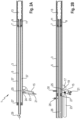
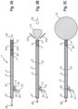
- a leak sealing device 1 The structure of a leak sealing device 1 is initially based on the embodiment in Figures 1A and B explained.
- Fig. 1A shows the leakage sealing device 1 in its storage position and Fig. 1B in their sealing position.
- the leak sealing device 1 comprises a tubular support unit 3 which extends in the longitudinal direction.
- a fluid connection 29 is provided in the form of a valve.
- the fluid connection 29 serves to connect the leak sealing device 1 to a fluid source (not shown), such as an external compressor or a fluid cartridge or gas bottle (not shown) in which a gaseous or liquid and / or powdery fluid for filling the sealing agent 13 is stored .
- the fluid either has the pressure required for the respective application in the fluid reservoir or can be placed under the required pressure via additional devices, such as the compressor.
- a seal 27 can optionally be provided for sealing the fluid connection 29.
- the fluid supply is shown schematically via the line from the fluid connection 29 to the sealing means 13.
- the sealing means 13 is connected to the carrier unit 3 via a fastening means 11, such as a threaded section or another suitable fastening.
- the sealing means 13 is provided in the storage position shown here as an unfilled balloon which surrounds the carrier unit 3.
- the sealing means 13 can be fastened in the storage position inside the carrier unit 3.
- the sealing means 13 can also be located entirely or partially within the front end of the carrier unit 3 and be flush with it or partially protrude.
- Fig. 1B shows the embodiment according to Fig. 1A in the sealing position. After actuation or release of the fluid source, the gaseous or liquid fluid is fed into the carrier unit 3 either via the fluid cartridge or the fluid connection 29. The sealing agent 13 is filled and expanded by the pressure of the fluid supplied. Fig. 1B shows the completely filled sealing means 13 or sealing ball 13, which is held on the carrier unit via the fastening means 11.
- the basic principle of the invention is that the leak sealing device 1 is inserted into a leak in its storage position, then the sealing agent is filled with a suitable fluid and in the sealing position the medium flowing out of the leak acts on the sealing agent 13 from the inside against the leak and thereby the leak is sealed (cf. also Fig. 4 and 5 ).
- FIGs 2A and B show the storage position of two further leak sealing devices or leak stop guns 1. These also each include the tubular support unit 3.
- a piston unit 5, 9 movable in the longitudinal direction is provided within the carrier unit 3.
- This includes a piston section 5 and a piston section 9, which can be provided in one piece or in several parts and are coupled to one another.
- the piston section 5 includes a fluid supply line which extends to its front end, which is on the right in the figure.
- the piston section 5 widens into a piston section 9.
- the two piston sections are coupled to one another via suitable fastening means, in the present case via a threaded connection.
- the sealing means 13 is connected to the piston section 9 via a fastening means, here via a threaded screw connection 11.
- the sealing means 13 is provided in the storage position as an unfilled balloon, approximately folded up. In the storage position, this extends to the front end of the carrier unit 3 and is flush with it. Alternatively, it can also partially protrude from the carrier unit 3.
- a pistol grip-like trigger device or holding device or release unit 15 is provided on the underside of the carrier unit, which is also called the straightening lance 3. This can be formed in one piece with the carrier unit 3 or else be separate and connected to the carrier unit 3.
- the release unit 15 includes a trigger 17, which is protected against unintentional actuation by a trigger guard 19. '
- a fluid cartridge in particular a carbon dioxide cartridge 23, is provided as a fluid delivery unit, which is coupled via a fluid supply line 25 to a compression space 37 provided within the carrier unit 3.
- the compression space 37 extends over the entire interior of the carrier unit 3 up to the seal 7.
- the carbon dioxide cartridge 23, with its fluid as an ejection agent, ensures that the sealing agent (sealing ball) 13 is conveyed out of the carrier unit/straightening lance 3, which is transported via the compression space 37 happens.
- This process is triggered mechanically by hand by actuating the trigger 17, whereby the carbon dioxide cartridge 23 is opened by removing a seal or a sealing strip 24 on its top, somewhat like a fire extinguisher, and is completely emptied.
- a fluid connection 21 is provided on the release unit 15 for connecting an external fluid source, for example a compressed air or other gas source or liquid source.
- the fluid connection 21 can also be provided as an alternative to the fluid cartridge 23. However, in this case both are provided.
- the fluid cartridge 23 ensures self-sufficient use of the leak sealing device or leak stop gun 1.
- the fluid connection 21 enables connection to an external fluid source, such as a compressor or comparable units that can supply pressurized fluid.
- a seal 27 which seals the interior, in particular the compression space 37 of the carrier unit 3, and is penetrated by the piston section 5, such that the piston section 5 partially protrudes backwards in the storage position.
- a further fluid connection 29 is optionally provided, via which the sealing agent or the sealing ball 13 can be filled.
- the sealing agent 13 is expelled from the carrier unit/straightening lance, the sealing agent 13 is used in the embodiment according to Fig. 2A via the connection 29 filled with the appropriate fluid up to its optimal sealing pressure in order to be able to close the leak. This process is controlled and monitored at the same time via a pressure control valve 29.
- the pressure control valve is located on the fluid connection 29.
- the embodiment according to Fig. 2B differs from the embodiment according to Fig. 2A in that the carbon dioxide cartridge or fluid source 23 is provided with larger dimensions and is partially arranged outside the extraction device or holding device 15.
- a second fluid connection or a pressure relief valve 21 is optionally provided.
- the pressure relief valve 21 serves to automatically release and regulate any excess pressure in the compression chamber 37 and/or the sealing means 13.
- the fluid supplied via the fluid supply line 25 first fills the compression chamber 37 and thereby drives the piston section 9 with the sealing agent out of the carrier unit 3.
- the piston section 5 penetrates the sealant 27, which is provided approximately close to and above the trigger device 15 in the storage position.
- the sealant 27 limits the compression space 37 to the rear and seals it.
- the expanding fluid acts on the piston unit 5, 9 via the fluid supply and drives the piston sections 5, 9 and the sealing agent 13 forward (cf. Fig. 2C ).
- the piston section 5 is advanced so far that in the sealing position it passes through the sealant 27 with its fluid supply line 26, so that the fluid can penetrate into the fluid line 5 via the further fluid supply line 26 and fill the expelled sealant 13.
- the fluid pressure(s) within the sealing means 13 and within the compression chamber 37 can be controlled via a valve unit 30 independently of one another or together by dispensing fluid to the outside, so that in particular the volume of the sealing means 13 can be adjusted as desired.
- This measure can be carried out in all embodiments of the invention and can be varied as desired in a known manner.
- Fig. 2C shows the completely filled sealing ball 13, which is connected to the piston section 9 via the thread 11 and is held there.
- the piston section 5 is connected to the compression chamber via the fluid supply line 26.
- a recoil protection 28 is provided in the form of a spring-loaded bolt. In the storage position, the bolt 28 is spring-loaded against the piston section 5. It's like in now Fig. 2C shown the piston section 5 is advanced into the sealing position and passes the bolt 28, the spring can push the bolt 28 into the release unit 3, so that the bolt 28 fixes the piston section 5 at its rear end and secures it against unintentional placement in its storage position prevents extension or movement in the carrier unit 3.
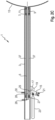
- FIG. 3A to C and Fig. 4 A further embodiment of the leak sealing device 1 according to the invention will now be based on 3A to 3C and 4 explained.
- the embodiment of the leak sealing device 1 shown differs from the embodiments according to Figures 1A and B as well as 2 A to C in that sliding shells 31a, 31b and a sliding tip 33 are provided at the front end as insertion aids.
- Fig. 3A shows the storage position of the leakage sealing device 1, in which the sliding shells 31a, b are completely accommodated and the sliding tip 33 is partially accommodated within the carrier unit 3.
- the sealing agent or the balloon 13 is also completely accommodated within the carrier unit 3 and is covered at its front end by the arrowhead-shaped sliding tip 33 and thus protected from damage.
- the sliding tip can also have alternative geometric configurations, for example a rounding or hemispherical shape or similar, and makes it easier to insert the leak sealing device into the leak.
- the sliding tip 33 is held in the storage position via a form fit and/or press fit or other suitable measures. For example, it can also be secured via a type of clamping ring (not shown). Alternatively, the sliding tip can also be secured with an adhesive with very low adhesive strength. This backup of the Sliding tip 33 gives way under pressure built up by the expulsion fluid, so that the clamping ring/form fit together with the sliding tip can emerge forward unhindered and the sealing agent 13 can freely penetrate into the leak.
- Fig. 3B shows the embodiment according to Fig. 3A in the sealing position with a partially filled sealing ball 13.
- a gaseous or liquid fluid is fed into the compression chamber 37 within the carrier unit 3 via the fluid supply line 25 either via the fluid cartridge 23 or the fluid connection 21.
- the resulting pressure of the fluid supplied causes the piston sections 5, 9 to be driven forward, whereby the sealing means 13, the sliding shells 31a, 31b and the sliding tip 33 are expelled or conveyed out of the carrier unit 3.
- the piston or the fluid line 5 provided therein is used to fill the sealing agent 13 with fluid.
- the fluid connection 29 is coupled to an external fluid source, such as a compressor (not shown) or another fluid delivery unit (not shown).
- the inflowing fluid fills the sealing agent 13 and can be controlled in quantity and pressure via a valve (not shown).
- the pressure of the fluid within the compression chamber 37 and within the fluid supply line of the piston section 5 is high enough to withstand the pressure of the outflowing medium 41.
- the fluid pressure for driving the piston 9 and filling the sealing ball 13 can be slightly higher than 1.5 bar.
- the fluid driving the sealing ball 13 and piston 9 is selected depending on the outflowing medium 41.
- the sliding shells 31a, 31b and the sliding tip 33 are forced out of the carrier unit 3. Since these only rest loosely or with a low fastening resistance in the storage position on the folded sealing ball 13, they can now fall off the sealing ball.
- the sliding shells 31a, b and the sliding tip 33 thus act as an insertion aid and protect the sealing ball from damage.
- piston section 9 is in its front end position, in which it is more or less flush with the front end of the carrier unit 3. Due to this forward movement of the piston section 9, the piston section 5 is simultaneously inserted further into the carrier unit 3, so that its rear end only protrudes slightly.
- Fig. 3C shows the completely filled sealing ball 13, which is connected to the piston section 9 via the fastening means 11 and is held there.
- the piston section 9 is coupled to the piston section 5 via a threaded section or companion piece 35.
- these two elements can also be formed in one piece.
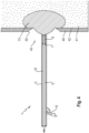
- Fig. 4 shows the embodiment Fig. 3A to C in the sealing position.
- the leak sealing device 1 is first inserted into the leak 43 of a container 40 and then triggered via the trigger mechanism 15.
- the sealing ball 13 is made of a sufficiently elastic and crack-resistant material so that it is not damaged by crack edges 45 of the leak 43.
- the sealing ball 13 After the sealing ball 13 has been filled, it is pressed against the leakage 43 via the internal pressure of the container 40 by the medium 41 located therein, which is for example in gaseous or liquid form, against the leak 43, which leads to a flattening of the surface of the sealing ball 13, so that it overflows extends away from the outer circumference of the leak and surrounds the leak 43 on both sides, is supported against the inner wall 42 of the container 40 and thereby completely or partially seals the leak.
- the medium 41 located therein which is for example in gaseous or liquid form
- the leak sealing device 1 is partially pulled out of the container, for example by a user pulling it back or by mechanically returning it, which leads to a tensioning of the sealing ball 13 in the leak 43, so that the crack edges 45 are at least partially separated from the container Sealing ball 13 are covered. This allows the sealing effect of the leakage sealing device 1 and in particular of the sealing ball 13 to be improved.
- Fig. 5A shows a further embodiment of the leak sealing device or leak stop gun 1 according to the invention.
- This is intended for sealing pipes 49 and differs in structure from the previous embodiments of the invention in that a recoil protection 47 is provided.
- a recoil protection 47 is provided in the case of pipes 49.
- the problem arises that the sealing ball 13 could possibly be driven out of the pipe by the outflowing medium 41 and the leak sealing device 1 must be held against the pressure of the outflowing medium 41 either manually or mechanically.
- Fig. 5A the sealing position of the leakage sealing device 1 is shown, in which the leakage sealing device 1 is inserted into a tube 49 and the sealing ball or the sealing means 13 is completely filled with the fluid (cf. 3A to 3C ).
- the recoil protection mechanism 47 develops its effect after the leakage sealing device 1 has been introduced completely or partially into the pipe 49.
- the recoil protection mechanism 47 comprises three safety arms 51a, b and c, which extend in a uniform angular distribution over the inner diameter of the pipe.
- the arms 51a, b, c can be connected to the front end of the carrier unit 3 of the leakage sealing device 1 via an attachment interface.
- the mounting interface 57a, b is exposed to the carrier unit from the front, so that a sleeve-like section of the mounting interface 57 completely encloses the front end of the carrier unit 3.
- the sleeve-like section corresponds in its internal dimensions to the external dimensions of the carrier unit 3 and is designed according to the geometry of the carrier unit 3, ie approximately angular, round, etc.
- the mounting interface 57 can be connected via a press fit or form fit and/or additionally via fastening means, such as screws the outer surface of the leak sealing device 1 releasably couple.
- the mounting interface 57 can also be welded, glued or fastened in another suitable manner, for example, to the front end of the carrier unit 3.
- the arms 51a, b and c are each movably linked to the mounting interface 57 via hinge pins or joint connections 59a, b and c.
- elastic means in the present embodiment springs 55a, b and c, are provided, which bias the arms 51a, b and c outwards in a spring-loaded manner, i.e. when the leak sealing device 1 is inserted into the tube 49, the springs 55a, b and c compressed, since the arms 51a, b and c are compressed, i.e. in the direction of the support unit 3.
- the springs 55a, b and c then act on the arms 51a, b and c inside the tube 49 against the inner tube surface, with an increasing internal tube pressure for this ensures that the arms 51 a, b, c wedge themselves more and more firmly in the tube 49, fixing the leak sealing device 1 there and thus ensuring safety.
- the arms 51a, b and c include an anti-slip surface 53a, b and c on their outside, i.e. the side facing the tube 49. This can be achieved by an anti-slip material, such as a coating, or by a mechanical design of the surface of the arms 51a, b and c, for example by a jagged or catch-like design.
- the arms 51a, b, c are braced and secured in a self-locking manner within the tube 49.
- Fig. 5B shows a top view of a cross-sectional representation along the interface AA Fig. 5A from behind.
- the arms 51a, b, c are shown schematically and are as shown in Fig. 5A shown, self-locking on the inner surface of the tube 49.
- the piston section or the fluid supply line 5 is also shown, as is the sealing ball 13.
- Fig. 6 shows an alternative embodiment of the invention, in which the leakage sealing device 1 is shown schematically and is mounted on a mount or a tripod 61.
- the mount or the stand 61 is used to introduce the leak sealing device 1 into leaks that can be located at different heights in a container, for example a tank.
- the tripod or the carriage 61 can be moved manually by several users or mechanically, for example using a suitable machine, to the container or tank to be sealed, and the height can be adjusted variably. This configuration can be particularly helpful in the case of toxic escaping gases in order to mechanically introduce the leakage dispensing device into the respective leakage.
Landscapes
- Engineering & Computer Science (AREA)
- General Engineering & Computer Science (AREA)
- Mechanical Engineering (AREA)
- Environmental & Geological Engineering (AREA)
- Chemical & Material Sciences (AREA)
- Combustion & Propulsion (AREA)
- Ocean & Marine Engineering (AREA)
- Loading And Unloading Of Fuel Tanks Or Ships (AREA)
- Filling Or Discharging Of Gas Storage Vessels (AREA)
- Sealing Devices (AREA)
- Pressure Vessels And Lids Thereof (AREA)
- Pipe Accessories (AREA)
Description
- Die Erfindung betrifft eine Leckage-Abdichtvorrichtung und deren Verwendung sowie ein Verfahren und System zum Abdichten einer Leckage in einem Behälter, Tank und/oder Rohr.
- Bei dem Behälter kann es sich beispielsweise um einen Silo, einen Gasspeicher beziehungsweise Gasbehälter einer Biogasanlage, einen Fermenter oder Rohr oder ähnliches handeln, die in ihrem Inneren ein flüssiges und/oder gasförmiges Medium beinhalten.
- In diesen Unterlagen beziehen sich Lagebezeichnungen, wie "oben", "unten", "unten vorne", "unten hinten", etc. stets aus der Sicht eines Nutzers beziehungsweise Bedieners der Leckage-Abdichtvorrichtung, mit Blick auf eine quer vor ihm angeordnete Leckage-Abdichtvorrichtung.
- Vorrichtungen zum Abdichten von Leckagen sind in unterschiedlichen Ausführungen bekannt. Beispielsweise offenbaren die
DD 240 769 A1 DD 232 461 A1 - Die
DE 103 31 378 A1 offenbart eine pneumatische Leckabdichtung durch Druckumkehr an geschlossenen Behältern und Rohrsystemen. Diese Leckabdichtung gestaltet sich in der Praxis aufwändig. - Die
DE 38 44 485 C2 offenbart ein Verfahren zur Leckabdichtung in Rohrleitungen, insbesondere Trinkwasserleitungen. Dabei wird zur Leckage-Reparatur eine Trinkwasserzufuhr zunächst außer Betrieb genommen und die Rohrleitung mit Druckluft entleert. - Ein solches Verfahren ist nicht praktikabel für die Abdichtung eines großen Gas- und/oder Fluidbehälters beispielsweise einer Biogasanlage, da eine vollständige Entleerung beziehungsweise ein Austritt des Fluids oder Gases in die Umwelt, vermieden werden soll.
- Schließlich offenbart die
AU 2008 243 596 A2 - Dieses Verfahren ist nur zur Verwendung bei Rohrleitungen und/oder Pipelines vorgesehen und der Körper lässt sich eher bei Außerbetriebnahme der Pipeline beziehungsweise Rohrleitung einsetzen.
- Insgesamt sind bekannte Leckage-Abdichtvorrichtungen und Verfahren oftmals unflexibel in der Handhabung und aufwändig im Aufbau. Eine Abdichtung einer Leckage von außen ist problematisch hinsichtlich einer sicheren Abdichtung, da das ausströmende Medium die Abdichtung verhindert oder erschwert.
-
US 4,329,132 A offenbart eine Leckage-Abdichtvorrichtung, bei der ein Beutel mit einem aushärtbaren Schaummaterial befüllbar ist, der außerhalb einer Zuführvorrichtung angeordnet ist. Der Beutel wird über ein Gummi oder Seil im nicht abdichtenden Zustand zusammengehalten. -
US 6,543,486 B1 offenbart eine Leckage-Abdichtvorrichtung zur Abdichtung von Leckagen beispielsweise in einem Boot. Innerhalb einer lanzenartigen Struktur ist ein Rohr vorgesehen, an dessen vorderem Ende eine aufblasbare Abdicht-Vorrichtung bzw. ein Beutel vorgesehen ist, der wiederum an seinem vorderen Ende von einer zerbrechlichen Abdeckung umgeben ist. -
US 3,841,256 A offenbart eine Vorrichtung zum Abdichten eines Lecks in einer Bootswand, bei der zum Abdichten ein Gehäuseteil manuell verschiebbar vorgesehen ist. -
GB189600320 -
US2011308656 A1 offenbart eine Vorrichtung und Methode zum Verschließen einer Hochdruckleitung. Die Vorrichtung umfasst eine Führungsleitung mit einer Pumpe an einem Ende und einem ausdehnbaren Verschluss am anderen Ende. Die Führungsleitung dient dazu, ein Material zuzuführen, das an einem Ende des beschädigten Rohres einen Verschluss erzeugen kann, wodurch verhindert werden soll, dass Öl oder andere Leitungsinhalte an der Quelle in das Rohr gelangen. - Aufgabe der vorliegenden Erfindung ist es, eine andere Leckage-Abdichtvorrichtung und ein System und Verfahren zur Abdichtung einer Leckage bereitzustellen, die obige Nachteile wenigstens teilweise überwinden, mindestens aber reduzieren.
- Diese Aufgabe wird durch die Gegenstände der unabhängigen Ansprüche 1 und 13 bis 15 gelöst.
- Die gattungsbildende Leckage-Abdichtvorrichtung weist gemäß Anspruch 1 somit zusätzlich folgende Merkmale auf: sie umfasst eine gehäuseartige Trägereinheit, wenigstens ein an einem Endbereich der Trägereinheit vorgesehenes, expandierbares Leckage-Abdichtmittel, das in seiner Lagerposition nicht oder nur geringfügig expandiert ist, und wenigstens einen Fluidanschluss und/oder wenigstens eine Fluidabgabeeinheit, der/die mit der Trägereinheit derart gekoppelt ist, dass bei Fluidzufuhr Fluid das Leckage-Abdichtmittel in dessen Abdichtposition über eine Fluidzuleitung wenigstens teilweise mit dem Fluid befüllt und expandiert, wobei in der Trägereinheit eine längsbeweglich gelagerte Kolbeneinheit vorgesehen ist, und das Leckage-Abdichtmittel mit der Kolbeneinheit und/oder der Trägereinheit und dem wenigstens einen Fluidanschluss und/oder der wenigstens einen Fluidabgabeeinheit derart gekoppelt ist, dass bei Fluidzufuhr das Fluid die Kolbeneinheit in die Abdichtposition vortreibt und das Leckage-Abdichtmittel über eine Fluidzuleitung wenigstens teilweise befüllt.
- Das erfindungsgemäße Verfahren zum Abdichten einer Leckage in einem Behälter, Tank und/oder Rohr umfasst die Schritte: Einführen einer erfindungsgemäßen Leckage-Abdichtvorrichtung wenigstens teilweise in eine Leckage in dem Behälter, Tank und/oder Rohr, und wenigstens teilweise Befüllen und Expandieren des Leckage-Abdichtmittels mit Fluid derart, dass das Leckage-Abdichtmittel aus dem Inneren des Behälters, Tanks und/oder Rohrs durch das dort ausströmende Medium gegen eine Innenwand des Behälters, Tanks und/oder Rohrs beaufschlagt wird und die Leckage abdichtet.
- Die Erfindung umfasst ebenso ein System zum Abdichten einer Leckage in einem Behälter, Tank und/oder Rohr umfassend eine erfindungsgemäße Leckage-Abdichtvorrichtung und eine mit einer Freigabeeinheit zur Fluidabgabe versehene Fluidzufuhrvorrichtung.
- Die Erfindung sieht auch eine Verwendung der erfindungsgemäßen Leckage-Abdichtvorrichtung zum Abdichten einer Leckage in einem Behälter, Tank und/oder Rohr vor.
- Vorteilhaft stellt die Erfindung eine einfache Ausgestaltung einer Leckage-Abdichtvorrichtung, eines Verfahrens und eines Systems bereit, die bzw. das insbesondere zur Vermeidung von Umweltkatastrophen und Umweltschäden vorgesehen ist. Die Leckage-Abdichtvorrichtung wird auch als Leck-Stopp-Pistole bezeichnet.
- Fluid im Sinne der Erfindung umfasst gasförmige und/oder flüssige Medien jeglicher Art und/oder Pulver/Granulat/Sand jeglicher Art sowie deren Mischungen.
- Die Leckagen können aufgrund unterschiedlichster Umstände in Behältern, Rohren etc. entstehen, beispielsweise durch einen umgestürzten Baum, einen herabfallenden Ast, herabfallende Ziegel, Materialermüdung, Anfahrschäden oder sonstige Ursachen. So können etwa Fremdkörper, wie beispielsweise Steine oder ähnliches, die z.B. im Rahmen der Biogasgewinnung mit den zu verarbeitenden beziehungsweise umzuwandelnden Stoffen in die jeweiligen Behälter eingebracht werden, einen Behälter von innen beschädigen.
- Die Vorrichtung, das Verfahren und das System sind vorteilhaft dazu ausgelegt, Leckagen jeglicher Art abzudichten und damit flexibel einsetzbar. Insbesondere ist deren Anwendung nicht auf Rohrleitungen oder rohrartig ausgestaltete Leitungen, die unter Druck stehendes Gas und/oder Fluid führen, vorgesehen. Ebenso kann in Abhängigkeit der Dimensionierung der jeweiligen Leckage-Abdichtvorrichtung diese auch zur Abdichtung von Leckagen in Gasbehältern oder Tanks, beispielsweise einer Biogasanlage, oder Fluidbehältern in beliebigen Abmessungen flexibel eingesetzt werden. Ein Einsatz ist beispielsweise an LKW's als Tankzug, an Behältern und Tanks unterschiedlicher Größen, an Booten und Schiffen, im Bereich der Flüssigmetall Verarbeitung mit sehr hohen Temperaturen, an allen Arten von Rohren wie etwa Abwasser, Gas, CO2, Stickstoff, Öl, Sole, Gülle oder an Lebensmittelleitungen wie Trinkwasser, Milch, Bier, Wein, Säfte, Cola, Fanta und sonstigen Getränkeleitungen, die alle unter anstehendem Druck geschlossen werden können, verwendbar.
- Insgesamt lässt sich die Leckage-Abdichtvorrichtung in beliebig geeigneten Dimensionen und Längen der Trägereinheit auch Richtlanze genannt, mit unterschiedlichen Dimensionen und Abmessungen des wenigstens einen Abdichtmittels bereitstellen.
- Auch sind die erfindungsgemäße Vorrichtung sowie das erfindungsgemäße Verfahren und System für verschiedenste Anwendungszwecke geeignet. Sie können beispielsweise in Abhängigkeit von der Dimensionierung bei Fahrzeugen, Tanklastzügen, der Feuerwehr bei Biogasanlagenbetreibern vorgehalten werden, um im jeweiligen Einsatzfall zur Anwendung zu kommen.
- Das der Erfindung zugrundeliegende Prinzip liegt darin, dass die Leckage-Abdichtvorrichtung von außen in ein Leck eines Behälters, Tanks, etc. pistolenartig eingeführt wird, dann das Leckage-Abdichtmittel mit einem geeigneten gasförmigen und/oder flüssigen Fluid, beispielsweise Druckluft oder Kohlensäure, und/oder Pulver/Granulat und deren Mischungen befüllt wird, und dann das Leck von innen abgedichtet wird. Das Abdichtmittel wird also mittels des einfließenden Fluids oder Druckluft oder Kohlensäure in das ausströmende Medium "hineingeschossen". Dabei beaufschlagt das ausströmende Medium das expandierte Abdichtmittel aus dem Behälterinneren also von innen gegen die Behälterinnenwand.
- Vorteilhaft lässt sich mit der erfindungsgemäßen Vorrichtung, dem Verfahren sowie dem System eine Leckage auch bei einem Ausströmen des Mediums fast und/oder vollständig schließen und abdichten. Die erfindungsgemäße Vorrichtung, das Verfahren sowie das System stellen somit eine Art "Erste Hilfe Maßnahme" dar für den schnellen und flexiblen Einsatz bei auftretenden Leckagen, so dass sich größere Umweltschäden verhindern lassen. Nach Einsatz der erfindungsgemäßen Vorrichtung, lässt sich dann die jeweilige Leckage entsprechend reparieren.
- Der Druck zum Befüllen des Abdichtmittels muss dabei nur so hoch sein, dass er das ausströmende Medium aus dem Behälter, dem Rohr, dem Tank oder Speicher einen höheren Druck entgegensetzt. Beispielsweise kann der Druck eines ausströmenden Fluids, bspw. aus einem Behälter einer Biogasanlage, etwa 1,5 bar betragen. Wenn das der Leckage-Abdichtvorrichtung zugeführte Fluid, bspw. Druckluft oder Kohlensäure, einen höheren Druck aufweist, lässt sich das Abdichtmittel im ausströmenden Medium befüllen. Insgesamt lassen sich vorteilhaft die erforderlichen Drücke der Fluidzufuhr beziehungsweise des ganz oder teilweise expandierten beziehungsweise befüllten Leckage-Abdichtmittels der jeweiligen Leckage-Situation anpassen. Die Leckage-Abdichtvorrichtung ist also grundsätzlich bei sämtlichen Drücken des ausströmenden Mediums einsetzbar. Bei hohen Drücken kommen dann entsprechende Spezial-Kompressoren zum Befüllen des Abdichtmittels zum Einsatz.
- Ebenso lassen sich unterschiedliche Fluide sei es gasförmig oder flüssig bereitstellen, mit denen das Abdichtmittel befüllt wird. Damit wird beim Abdichten beispielsweise einer Gasleitung das Abdichtmittel nicht mit Luft befüllt, um eine etwaige Explosionsgrenze nicht unnötig zu erhöhen und eine Gefährdung für den Nutzer bereitzustellen.
- Da jede Leckage ein anderes Fluid zum Befüllen des Abdichtmittels erfordert, lassen sich jeweils entsprechend geeignete Fluide flexibel einsetzen, bspw. Kohlensäuregas, Druckluft, Sauerstoff oder sonstige Gase. Ebenso sind geeignete Flüssigkeiten, beispielsweise Öle und/oder Pulver/Granulate und deren Mischungen oder ähnliches einsetzbar. Dabei ist nur darauf zu achten, dass das zugeleitete Fluid mit dem ausströmenden Medium harmoniert, d.h. eine gefährliche Mischung, die etwa eine Explosionsgefahr hervorruft, wie etwa eine Kombination aus Sauerstoff und Methan und/oder anderen Stoffen verhindert wird.
- Das Leckage-Abdichtmittel kann bspw. ballonartig vorgesehen sein, so dass es sich nach einem Austreiben aus der Vorrichtung innerhalb des Behälters auffüllt und dann durch den Druck des ausströmenden Mediums von innen gegen die Leckage gedrückt wird, derart, dass diese abgedichtet wird. Durch Anwenden einer Zugkraft auf die Leckage-Abdichtvorrichtung vom Behälter weg, lässt sich die Abdichtung der Leckage verbessern und insbesondere der Sitz des Abdichtmittels gegenüber dem Behälter anpassen.
- Die Trägereinheit kann beliebig geeignete geometrische Ausgestaltungen, beispielsweise eckig, rund, rechteckig oder anders aufweisen. In der Praxis hat sich eine rohrartige Ausgestaltung als flexibel erwiesen. Eine rohrartige Ausgestaltung der Trägereinrichtung ermöglicht eine einfache Einführung in eine Leckage.
- Die Trägereinheit ist vorteilhaft aus einem stabilen, aber leichten Material vorgesehen, um eine einfache Handhabung und schnellen Einsatz zum Einsatzort zu gewährleisten. Bei dem Material kann es sich beispielsweise um einen stoßfesten Kunststoff, ein Metall etwa Aluminium oder eine Metalllegierung oder auch um einen Verbundwerkstoff handeln. Das Abdichtmittel ist aus einem flexiblen und expandierbaren Material beispielsweise Kunststoff oder Kunststoffverbundstoffen vorgesehen. Ebenso können Kohlenstoffe bzw. Kohlenstoffgewebe (für extrem heiße Materialien) und Glasfaser verwendet werden. Die Materialwahl ist derart, dass das Abdichtmittel ballonartig auffüllbar und insbesondere dehnbar vorgesehen ist, um beispielsweise auf herausgebrochene Kanten der Leckage besser aufsitzen zu können. Das Material ist vom jeweils vorgesehenen Einsatzzweck abhängig und bringt - sofern erforderlich - eine gewisse Schnittfestigkeit mit.
- Die wenigstens eine Fluidabgabeeinheit kann beispielsweise als eine Kohlensäurepatrone oder Druckluftpatrone vorgesehen sein, so dass die Leckage-Abdichtvorrichtung autark verwendet werden kann und keine externe Fluidquelle benötigt.
- Alternativ oder zusätzlich kann ein Fluidanschluss vorgesehen sein, der beispielsweise mit einer externen Druckluftanlage, einem Kompressor, einer Gasflasche, einem Flüssigkeitsbehälter oder ähnlich geeigneten Mitteln koppelbar ist, um das jeweilige Abdichtmittel zu befüllen. Beim erfindungsgemäßen System kann eine an der Druckluftanlage, dem Kompressor, der Gasflasche etc. vorgesehene Freigabeeinheit zur Fluidabgabe betätigt werden, so dass eine Freigabeeinheit an der Leckage-Abdichtvorrichtung nicht erforderlich ist. Auch können bedarfsabhängig ein oder mehrere Fluidanschluss/-anschlüsse und eine oder mehrere Fluid-Abgabeeinheit(en) nebeneinander vorgesehen sein
- Insgesamt stellen die erfindungsgemäße Leckage-Abdichtvorrichtung, das System und Verfahren eine flexible Vorrichtung und Verfahren bereit, um sowohl leckgeschlagene Behälter und Tanks als auch leckgeschlagene Rohre abzudichten. Damit verhindern sie, dass leckgeschlagene Behälter oder Speicher vollständig auslaufen und somit Umweltkatastrophen bewirken. Insbesondere, sind die Leckage-Abdichtvorrichtung, das System und Verfahren geeignet, sowohl dem unter Druck ausströmenden Medium zu begegnen und dessen Auslaufen zu stoppen als auch zu den meist unregelmäßig gezeichneten oder gebildeten Leckage-Austrittsöffnungen, durch die das Medium entweicht, zu begegnen und sich daran anzupassen.
- Bevorzugt umfasst die Leckage-Abdichtvorrichtung weiter eine in der Trägereinheit längsbeweglich gelagerte Kolbeneinheit, wobei das Leckage-Abdichtmittel mit der Kolbeneinheit und/oder der Trägereinheit und dem wenigstens einen Fluidanschluss und/oder der wenigstens einen Fluidabgabeeinheit gekoppelt ist, derart, dass bei Fluidzufuhr das Fluid die Kolbeneinheit in die Abdichtposition vortreibt und das Leckage-Abdichtmittel über eine Fluidzuleitung wenigstens teilweise befüllt.
- Dabei ist das Leckage-Abdichtmittel zwischen einer Lagerposition, in der sich das Leckage-Abdichtmittel wenigstens teilweise innerhalb oder außerhalb der Trägereinheit befindet, und einer Abdichtposition, in der sich das Leckage-Abdichtmittel zum Abdichten der Leckage wenigstens teilweise außerhalb der Trägereinheit befindet, beweglich gelagert.
- Eine Lagerung des Leckage-Abdichtmittels wenigstens teilweise innerhalb der Trägereinheit schützt das Leckage-Abdichtmittel vor Beschädigungen. Die Kolbeneinheit stellt ein Austreiben in die Abdichtposition sicher.
- Die Kolbeneinheit und das Leckage-Abdichtmittel können zeitgleich ausgetrieben und befüllt werden. Bevorzugt wird zuerst die Kolbeneinheit mit dem Leckage-Abdichtmittel ausgetrieben und dann das Leckage-Abdichtmittel befüllt.
- Bevorzugt umfasst die Leckage-Abdichtvorrichtung wenigstens einen Freigabeeinheit zum Halten der Leckage-Abdichtvorrichtung und zum Betätigen des wenigstens einen Fluidanschlusses und/oder der wenigstens einen Fluidabgabeeinheit zur Fluidabgabe.
- Die Freigabeeinheit kann bspw. nach Art eines Pistolengriffs an der Trägereinheit integral vorgesehen sein oder daran gekoppelt werden. Die Freigabeeinheit kann einen Abzugsmechanismus umfassen. Bei Betätigung des Abzugs lässt sich der wenigstens eine Fluidanschlusses und/oder die wenigstens einen Fluidabgabeeinheit zur Fluidabgabe auslösen. Beispielsweise kann die Fluidabgabeeinheit nach Art eines Feuerlöschers ausgelöst werden und bei Betätigung des Abzugs eine Dichtung oder Öffnung der Fluidabgabeeinheit, etwa durch Abzug eines Dichtstreifens, freigegeben werden so dass Fluid ausströmen kann.
- Bevorzugt ist bei der Leckage-Abdichtvorrichtung der wenigstens eine Fluidanschluss und/oder die wenigstens eine Fluidabgabeeinheit mit einer mit der Kolbeneinheit gekoppelten oder darin integrierten Fluidzuleitung zum Befüllen des Leckage-Abdichtmittels verbindbar.
- Diese Maßnahme stellt eine sichere Befüllung des Leckage-Abdichtmittels sicher.
- Bevorzugt umfasst die Leckage-Abdichtvorrichtung wenigstens einen zweiten Fluidanschlusses oder wenigstens eine zweite Fluidabgabeeinheit zum Vortreiben des Kolbens in die Abdichtposition.
- Diese Maßnahme ermöglicht eine flexible Handhabung und einen variablen Einsatz der Leckage-Abdichtvorrichtung.
- Vorzugsweise umfasst die Leckage-Abdichtvorrichtung weiter wenigstens eine zweite Freigabeeinheit zum Freigeben des zweiten Fluidanschlusses oder der zweiten Fluidabgabeeinheit zur Fluidabgabe.
- Mit dieser Maßnahme lassen sich der zweite Fluidanschluss oder die zweite Fluidabgabeeinheit variabel einsetzen und steuern.
- Bevorzugt sind bei der Leckage-Abdichtvorrichtung die Trägereinheit und/oder die Kolbeneinheit einstückig ausgebildet.
- Dies ermöglicht eine konstruktiv einfache Ausgestaltung.
- Vorzugweise ist bei der Leckage-Abdichtvorrichtung die Trägereinheit und/oder die Kolbeneinheit mehrteilig ausgebildet.
- Mit dieser Maßnahme lassen sich insbesondere Dimension und Abmessung der Leckage-Abdichtvorrichtung variieren und die Leckage-Abdichtvorrichtung bspw. zum Transport zerlegen.
- Bevorzugt umfasst die Leckage-Abdichtvorrichtung wenigstens ein Einführhilfsmittel zur Einführung der Leckage-Abdichtvorrichtung in die Leckage, das in der Lagerposition das Leckage-Abdichtmittels wenigstens teilweise umgibt und in der Abdichtposition ein Befüllen des Leckage-Abdichtmittels erlaubt.
- Das Einführhilfsmittel verringert den Widerstand beim Eindringen der Leckage-Abdichtvorrichtung in das Medium und ermöglicht somit ein leichteres Eindringen. Ferner dient das Einführhilfsmittel als Schutz des Leckage-Abdichtmittels und hilft auch, eine größere Abdrift der Leckage-Abdichtvorrichtung innerhalb der Leckage zu verhindern.
- Das wenigstens eine Einführhilfsmittel kann aus geeigneten Materialien, beispielsweise Kunststoff, Polyester, hitzebeständigem Material wie Kohlenfaser, Glasfaser oder ähnlichen Materialien hergestellt sein. Das Material wird in Abhängigkeit vom Einsatzzweck ausgewählt.
- Bevorzugt umfasst bei der Leckage-Abdichtvorrichtung das wenigstens eine Einführhilfsmittel, wenigstens eine Gleitspitze und wenigstens eine Gleitschale zur Einführung der Leckage-Abdichtvorrichtung in die Leckage.
- Nach dem Austreiben können die Gleitschalen und die Gleitspitze einfach seitlich oder nach unten wegfallen, da sie am Leckage-Abdichtmittel angelagert sein können. Mit dieser Maßnahmen lässt sich das Abdichtmittel frei befüllen und expandieren.
- Vorzugsweise umfasst die Leckage-Abdichtvorrichtung weiter wenigstens eine Rückstoßsicherung zum Festlegen der Leckage-Abdichtvorrichtung in einem Behälter, insbesondere in einem Rohr, wobei die Rückstoßsicherung mit der Leckage-Abdichtvorrichtung lösbar verbindbar vorgesehen sein kann.
- Die Rückstoßsicherung lässt sich wahlweise in Abhängigkeit vom Einsatzort zusätzlich montieren. Dazu kann ein geeigneter Koppelmechanismus vorgesehen, bspw. über geeignete Befestigungsmittel, etwa Schellen oder Hülsen und Schrauben. Die Rückstoßsicherung ist bevorzugt selbstsichernd vorgesehen, so dass die Leckage-Abdichtvorrichtung bei einem Rohreinsatz nicht durch das ausströmende Medium aus dem Rohr getrieben wird.
- Vorzugsweise umfasst bei der Leckage-Abdichtvorrichtung die Rückstoßsicherung wenigstens zwei selbstklemmende oder klemmende Rückhaltearme, die federbelastet vorgespannt sind und/oder deren Oberfläche rutschhemmend vorgesehen ist.
- Diese Maßnahme ist eine einfache und kostengünstige Ausgestaltung der Rückstoßsicherung. Die Arme lassen sich einzeln oder zusammen seitlich an der Trägereinheit montieren und stützen sich dann bspw. federbelastet an der Rohrinnenfläche ab. Eine Oberflächenbearbeitung der Arme kann eine rutschhemmende Struktur bereitstellen, z.B. Nuten, Riefen, Fischhautstruktur etc. Alternativ oder zusätzlich keine auch eine rutschhemmende Beschichtung auf die Arme aufgetragen oder dort gekoppelt werden, bspw. eine Gummischicht. Da das Medium aus dem Behälter die Leckage-Abdichtvorrichtung und damit die Rückstoßsicherung beaufschlagt, verkeilt sich diese selbstsichernd insbesondere im Rohr.
- Bevorzugt umfasst die Leckage-Abdichtvorrichtung weiter eine Anschlussschnittstelle zur Montage auf einem Stativ oder einer Lafette.
- Diese Maßnahme ermöglicht eine schnelle und flexible Montage an einer Lafette oder Stativ und erweitert damit den Einsatzbereich der Leckage-Abdichtvorrichtung.
- Bevorzugt umfasst die Leckage-Abdichtvorrichtung weiter eine Lafette oder Stativ, auf der die Leckage-Abdichtvorrichtung montierbar ist.
- Die Lafette oder Stativ kann fahrbar vorgesehen sein, was den Einsatz erleichtert. Auch lässt sich bspw. eine Lafette oder Stativ motorisieren und ggf. fernsteuern, so dass bei ausströmenden etwa giftigen oder gefährlichen Medien keine Nutzer gefährdet werden. Zusätzlich ermöglichen eine Lafette oder Stativ einen flexiblen Einsatz, da Leckagen auch in verschiedenen Höhen abgedichtet werden können.
- Ausführungsbeispiele der Erfindung sind im Folgenden unter Bezugnahme auf die beigefügten, schematischen Zeichnungen näher erläutert. Darin zeigen:
-
Fig. 1A eine Längsschnittdarstellung einer erfindungsgemäßen Leckage-Abdichtvorrichtung in einer Ansicht von der Seite; -
Fig. 1B eine Längsschnittansicht der Ausführungsform ausFig. 1A mit einem expandierten Abdichtmittel in der Abdichtposition; -
Fig. 2A eine Längsschnittansicht einer weiteren Ausführungsform der erfindungsgemäßen Leckage-Abdichtvorrichtung in einer Lagerposition in einer Ansicht von der Seite; -
Fig. 2B eine Längsschnittansicht einer weiteren Ausführungsform der erfindungsgemäßen Leckage-Abdichtvorrichtung in einer Lagerposition in einer Ansicht von der Seite; -
Fig. 2C eine Längsschnittansicht der Ausführungsform der erfindungsgemäßen Leckage-Abdichtvorrichtung ausFig. 2B mit einem expandierten Abdichtmittel in der Abdichtposition; -
Fig. 3A eine Längsschnittansicht einer weiteren Ausführungsform der erfindungsgemäßen Leckage-Abdichtvorrichtung in einer Lagerposition in einer Ansicht von der Seite; -
Fig. 3B eine Längsschnittansicht auf die Ausführungsform ausFig. 3A mit einem expandierenden Abdichtmittel in der Abdichtposition; -
Fig. 3C eine Längsschnittdarstellung der Ausführungsform gemäßFig. 3A und 3B in der Abgabeposition mit vollständig gefülltem und expandiertem Abdichtmittel; -
Fig. 4 eine Längsschnittansicht der Ausführungsform ausFig. 3A bis 3C in der Abdichtposition, in der das Abdichtmittel eine Leckage in einem Behälter abdichtet; -
Fig. 5A eine Längsschnittansicht einer weiteren Ausführungsform der erfindungsgemäßen Leckage-Abdichtvorrichtung zur Abdichtung einer Leckage in einem Rohr in der Abdichtposition; -
Fig. 5B eine Querschnittsansicht der Ausführungsform aus Fig. A entlang der Schnittebene A-A von hinten; und -
Fig. 6 eine perspektivische Darstellung einer weiteren Ausführungsform der erfindungsgemäßen Leckage-Abdichtvorrichtung, bei dem eine erfindungsgemäße Leckage-Abdichtung auf einem Stativ beziehungsweise einer Lafette montiert ist. - Der Aufbau einer Leckage-Abdichtvorrichtung 1 wird zunächst anhand der Ausführungsform in
Fig. 1A und B erläutert.Fig. 1A zeigt die Leckage-Abdichtvorrichtung 1 in ihrer Lagerposition undFig. 1B in ihrer Abdichtposition. - Die Leckage-Abdichtvorrichtung 1 umfasst eine rohrartige Trägereinheit 3, die sich in Längsrichtung erstreckt. Am hinteren Ende der Trägereinheit 3 ist ein Fluidanschluss 29 in Form eines Ventils vorgesehen. Der Fluidanschluss 29 dient zur Verbindung der Leckage-Abdichtvorrichtung 1 mit einer Fluidquelle (nicht gezeigt), etwa ein externer Kompressor oder einer Fluidpatrone oder Gasflasche (nicht gezeigt) in der ein gasförmiges oder flüssiges und/oder pulverförmiges Fluid zum Befüllen des Abdichtmittel 13 gespeichert ist. Das Fluid weist entweder den für den jeweiligen Einsatzzweck erforderlichen Druck im Fluidspeicher auf oder kann über Zusatzeinrichtungen, wie etwa den Kompressor, unter den erforderlichen Druck gesetzt werden. Zusätzlich kann eine Dichtung 27 optional zum Abdichten des Fluidanschlusses 29 vorgesehen sein. Die Fluidzuführung ist schematisch über den Strich vom Fluidanschluss 29 bis in das Abdichtmittel 13 dargestellt.
- An der Vorderseite der Trägereinheit 3 ist das Abdichtmittel 13 über ein Befestigungsmittel 11, etwa ein Gewindeabschnitt oder eine sonstige geeignete Befestigung, mit der Trägereinheit 3 verbunden. Das Abdichtmittel 13 ist in der hier gezeigten Lagerposition als nicht befüllter Ballon vorgesehen, der die Trägereinheit 3 umgibt. Ebenso kann das Abdichtmittel 13 in der Lagerposition im Inneren der Trägereinheit 3 befestigt sein. Alternativ kann sich das Abdichtmittel 13 auch in der Lagerposition ganz oder teilweise innerhalb des vorderen Endes der Trägereinheit 3 befinden und bündig damit abschließen oder teilweise vorstehen.
-
Fig. 1B zeigt die Ausführungsform gemäßFig. 1A in der Abdichtposition. Nach einer Betätigung bzw. Freigabe der Fluidquelle wird entweder über die Fluidpatrone oder den Fluidanschluss 29 das gasförmige oder flüssige Fluid in die Trägereinheit 3 zugeleitet. Durch den Druck des zugeführten Fluids wird das Abdichtmittel 13 befüllt und expandiert.Fig. 1B zeigt das vollständig befüllte Abdichtmittel 13 bzw. Dichtungsball 13, der über das Befestigungsmittel 11 an der Trägereinheit gehalten wird. - Das Grundprinzip der Erfindung liegt darin, dass die Leckage-Abdichtvorrichtung 1 in ihrer Lagerposition in eine Leckage eingeführt wird, dann das Abdichtmittel mit einem geeigneten Fluid befüllt wird und in der Abdichtposition das aus der Leckage ausströmende Medium das Abdichtmittel 13 von innen gegen die Leckage beaufschlagt und dadurch die Leckage abgedichtet wird (Vgl. auch
Fig. 4 und5 ). -
Fig. 2A und B zeigen die Lagerposition zweier weiterer Leckage-Abdichtvorrichtungen bzw. Leck-Stopp-Pistolen 1.Diese umfassen ebenso jeweils die rohrartige Trägereinheit 3. - Innerhalb der Trägereinheit 3 ist jeweils eine in Längsrichtung bewegliche Kolbeneinheit 5, 9 vorgesehen. Diese umfasst einen Kolbenabschnitt 5 und einen Kolbenabschnitt 9, die einstückig oder mehrteilig vorgesehen sein können und miteinander gekoppelt sind. Im Inneren umfasst der Kolbenabschnitt 5 eine Fluidzuleitung, die sich zu seinem vorderen, in der Figur rechten Ende erstreckt. An der Vorderseite der Trägereinheit 3 ist ein Dichtungsmittel 7, bevorzugt ein elastisches Dichtungsmittel etwa ein Gummistopfen oder eine vergleichbare Ausgestaltung im Inneren der Trägereinheit 3 vorgesehen, die den Kolbenabschnitt 9 umgibt.
- An der Vorderseite der Leckage-Abdichtvorrichtung oder auch Leck-Stopp-Pistole 1 genannt verbreitert sich der Kolbenabschnitt 5 in einen Kolbenabschnitt 9. Die beiden Kolbenabschnitte sind über geeignete Befestigungsmittel miteinander gekoppelt, vorliegend über eine Gewindeverbindung. Am Ende des Kolbenabschnitts 9, ist das Abdichtmittel 13 über ein Befestigungsmittel, hier über eine Gewindeverschraubung 11 mit dem Kolbenabschnitt 9 verbunden.
- Das Abdichtmittel 13 ist in diesen beiden Ausführungsformen in der Lagerposition als ein nicht befüllter Ballon vorgesehen, etwa zusammengefaltet. Dieser erstreckt sich in der Lagerposition bis zum vorderen Ende der Trägereinheit 3 und schließt bündig damit ab. Alternativ kann er auch teilweise aus der Trägereinheit 3 vorstehen.
- An der Unterseite der Trägereinheit, die auch Richtlanze 3 genannt wird, ist eine pistolengriffartige Abzugseinrichtung bzw. Haltevorrichtung oder Freigabeeinheit 15 vorgesehen. Diese kann einstückig mit der Trägereinheit 3 ausgebildet sein oder auch separat und mit der Trägereinheit 3 verbunden sein. Die Freigabeeinheit 15 umfasst einen Abzug 17, der von einem Abzugsbügel 19 gegen eine unbeabsichtigte Betätigung geschützt ist. '
- Im Inneren der Freigabeeinheit 15 ist eine Fluidpatrone, insbesondere eine Kohlensäurepatrone 23 als Fluidabgabeeinheit vorgesehen, die über eine Fluidzuleitung 25 mit einem innerhalb der Trägereinheit 3 vorgesehenen Verdichtungsraum 37 gekoppelt ist. Der Verdichtungsraum 37 erstreckt sich über das gesamte Innere der Trägereinheit 3 bis hin zur Dichtung 7. Die Kohlensäurepatrone 23 sorgt mit ihrem Fluid als Ausdrückmittel dafür, dass das Abdichtmittel (Abdichtungsball) 13 aus der Trägereinheit/Richtlanze 3 heraus befördert wird, welches über den Verdichtungsraum 37 geschieht. Ausgelöst wird dieser Vorgang mechanisch per Hand durch Betätigungen des Abzugs 17 wodurch die Kohlensäurepatrone 23 durch Entfernen einer Dichtung oder eines Dichtstreifens 24 an ihrer Oberseite geöffnet wird, etwa wie bei einem Feuerlöscher, und vollständig entleert wird.
- Zusätzlich ist an der Freigabeeinheit 15 ein Fluidanschluss 21 für den Anschluss einer externen Fluidquelle, beispielsweise einer Druckluft- oder sonstigen Gasquelle oder Flüssigkeitsquelle vorgesehen. Der Fluidanschluss 21 kann auch alternativ zur Fluidpatrone 23 vorgesehen sein. Im vorliegenden Fall sind jedoch beide vorgesehen. Die Fluidpatrone 23 gewährleistet einen autarken Einsatz der Leckage-Abdichtvorrichtung bzw. Leck-Stopp-Pistole 1. Der Fluidanschluss 21 ermöglicht den Anschluss an eine externe Fluidquelle, etwa einen Kompressor oder vergleichbare Einheiten, die Druck beaufschlagtes Fluid zuführen können.
- Am hinteren Ende der Trägereinheit 3 ist eine den Innenraum, insbesondere den Verdichtungsraum 37 der Trägereinheit 3 abdichtende Dichtung 27 vorgesehen, die von dem Kolbenabschnitt 5 durchdrungen ist, derart, dass der Kolbenabschnitt 5 in der Lagerposition teilweise nach hinten vorsteht. Am hinteren Ende des Kolbenabschnitts 5 mit seiner darin befindlichen Fluidzuleitung ist optional ein weiterer Fluidanschluss 29 vorgesehen, über den sich das Abdichtmittel beziehungsweise der Abdichtball 13 befüllen lässt.
- Ist das Abdichtmittel (Dichtungsball) 13 aus der Trägereinheit/Richtlanze ausgetrieben, wird das Abdichtmittel 13 bei der Ausführungsform gemäß
Fig. 2A über den Anschluss 29 mit dem entsprechenden Fluid bis zu seinem optimalen Abdichtungsdruck aufgefüllt, um somit die Leckage verschließen zu können. Dieser Vorgang wird über ein Drucksteuerventil 29 gesteuert und gleichzeitig auch überwacht. Das Drucksteuerventil befindet sich an dem Fluidanschluss 29. - Die Ausführungsform gemäß
Fig. 2B unterschiedet sich von der Ausführungsform gemäßFig. 2A dadurch, dass die Kohlensäurepatrone bzw. Fluidquelle 23 größer dimensioniert vorgesehen ist und teilweise außerhalb der Abzugseinrichtung bzw. Haltevorrichtung 15 angeordnet ist. Außerdem ist bei dieser Ausführungsform optional ein zweiter Fluidanschluss oder ein Überdruckventil 21 vorgesehen. Das Überdruckventil 21 dient dazu einen etwaigen Überdruck in dem Verdichtungsraum 37 und/oder dem Abdichtmittel 13 selbsttätig abzulassen und zu regulieren. Bei Fluidfreigabe bzw. Fluidzufuhr über die Kohlensäurepatrone bzw. Fluidquelle 23 befüllt das zugeführte Fluid über die Fluidzuleitung 25 zunächst den Verdichtungsraum 37 und treibt dabei den Kolbenabschnitt 9 mit dem Abdichtmittel aus der Trägereinheit 3 aus. Der Kolbenabschnitt 5 durchdringt dazu das Dichtmittel 27, das in der Lagerposition in etwa nahe zu und oberhalb der Abzugseinrichtung 15 vorgesehen ist. Das Dichtmittel 27 begrenzt den Verdichtungsraum 37 nach hinten und dichtet ihn ab. - Über die Fluidzufuhr beaufschlagt das sich expandierende Fluid die Kolbeneinheit 5, 9 und treibt die Kolbenabschnitte 5, 9 und das Abdichtmittel 13 nach vorne aus (vgl.
Fig. 2C ). Der Kolbenabschnitt 5 wird dabei soweit vorgetrieben, dass er in der Abdichtposition mit seiner Fluidzuleitung 26 das Dichtmittel 27 passiert, so dass das Fluid über die weitere Fluidzuleitung 26 in die Fluidleitung 5 eindringen kann und darüber das ausgetriebene Abdichtmittel 13 befüllt. - Der oder die Fluiddrücke innerhalb des Abdichtmittels 13 sowie innerhalb des Verdichtungsraums 37 lassen sich über eine Ventileinheiten 30 jeweils unabhängig voneinander oder gemeinsam durch eine Fluidabgabe nach außen steuern, so dass sich insbesondere das Volumen des Abdichtmittels 13 beliebig anpassen lässt.
- Diese Maßnahme lässt sich bei sämtlichen Ausführungsformen der Erfindung vornehmen und in bekannter Weise beliebig variieren.
-
Fig. 2C zeigt den vollständig befüllten Dichtungsball 13, der über das Gewinde 11 mit dem Kolbenabschnitt 9 verbunden ist und dort gehalten wird. Der Kolbenabschnitt 5 ist über die Fluidzuleitung 26 mit dem Verdichtungsraum verbunden. Zusätzlich ist eine Rückstoßsicherung 28 in Form eines federbelasteten Bolzens vorgesehen. In der Lagerposition liegt der Bolzen 28 federbelastet am Kolbenabschnitt 5 an. Ist nun wie inFig. 2C gezeigt der Kolbenabschnitt 5 in die Abdichtposition vorgetrieben und passiert den Bolzen 28, kann die Feder den Bolzen 28 in die Freigabeneinheit 3 hinein drängen, so dass der Bolzen 28 den Kolbenabschnitt 5 an dessen hinterem Ende festlegt und gegen ein unbeabsichtigtes Verbringen in dessen Lagerposition sichert sowie ein Ausfahren aus oder Bewegen in der Trägereinheit 3 verhindert. - Eine weitere Ausführungsform der erfindungsgemäßen Leckage-Abdichtvorrichtung 1 wird nun anhand der
Fig. 3A bis 3C und4 erläutert. Die inFig. 3A bis C undFig. 4 gezeigte Ausführungsform der Leckage-Abdichtvorrichtung 1 unterscheidet sich von den Ausführungsformen gemäßFig. 1A und B sowie2 A bis C dadurch, dass am vorderen Ende Gleitschalen 31a, 31b sowie eine Gleitspitze 33 als Einführungshilfsmittel vorgesehen sind. -
Fig. 3A zeigt die Lagerposition der Leckage-Abdichtvorrichtung 1, in der die Gleitschalen 31a, b vollständig und die Gleitspitze 33 teilweise innerhalb der Trägereinheit 3 aufgenommen sind. Das Abdichtmittel beziehungsweise der Ballon 13 ist ebenso vollständig innerhalb der Trägereinheit 3 aufgenommen und wird an seinem vorderen Ende über die pfeilspitzenartig ausgebildete Gleitspitze 33 abgedeckt und somit vor Beschädigungen geschützt. Die Gleitspitze kann auch alternative geometrische Ausgestaltungen, beispielsweise eine Abrundung oder Halbkugelform oder ähnliches, aufweisen und erleichtert ein Einführen der Leckage-Abdichtvorrichtung in die Leckage. Die Gleitspitze 33 ist etwa über Formpassung und/oder Presspassung oder andere geeignete Maßnahmen in der Lagerposition gehalten. Beispielsweise kann sie auch über eine Art Klemmring (nicht gezeigt) gesichert sein. Alternativ kann die Gleitspitze auch mit einem Kleber mit sehr geringer Klebekraft gesichert werden. Diese Sicherung der Gleitspitze 33 gibt bei Druck, der durch das Austriebs-Fluid aufgebaut wird, nach, sodass der Klemmring/Formpassung zusammen mit der Gleitspitze ungehindert nach vorne austreten können und das Abdichtmittel 13 frei in die Leckage eindringen kann. -
Fig. 3B zeigt die Ausführungsform gemäßFig. 3A in der Abdichtposition mit einem teilweise befüllten Abdichtball 13. Nach Betätigung des Abzugs 17 wird entweder über die Fluidpatrone 23 oder den Fluidanschluss 21 ein gasförmiges oder flüssiges Fluid in den Verdichtungsraum 37 innerhalb der Trägereinheit 3 über die Fluidzuleitung 25 zugeleitet. Durch den entstehenden Druck des zugeführten Fluids werden die Kolbenabschnitte 5, 9 nach vorne getrieben, wodurch das Abdichtmittel 13, die Gleitschalen 31a, 31b sowie die Gleitspitze 33 aus der Trägereinheit 3 ausgetrieben bzw. heraus gefördert werden. - Der Kolben bzw. die darin vorgesehene Fluidleitung 5 wird für die Befüllung des Abdichtmittels 13 mit Fluid verwendet. Dazu wird der Fluidanschluss 29 mit einer externen Fluidquelle, etwa ein Kompressor (nicht gezeigt) oder einer weiteren Fluidabgabeeinheit (nicht gezeigt) gekoppelt. Das einströmende Fluid befüllt das Abdichtmittel 13 und lässt sich über ein nicht gezeigtes Ventil in der Menge sowie im Druck steuern.
- Der Druck des Fluids innerhalb des Verdichtungsraums 37 sowie innerhalb der Fluidzuleitung des Kolbenabschnitts 5 ist so hoch, um den Druck des ausströmenden Mediums 41 zu widerstehen. So kann beispielsweise bei einem Innendruck des ausströmenden Mediums 41 von 1,5 bar der Fluiddruck zum Vortreiben des Kolbens 9 und zum Auffüllen des Abdichtballs 13 etwas höher als 1,5 bar sein. Das den Abdichtball 13 und Kolben 9 vortreibende Fluid wird in Abhängigkeit des ausströmenden Mediums 41 gewählt.
- Beim Befüllen des Abdichtmittels beziehungsweise Ballons 13 und Austreiben der Kolbenabschnitte 5, 9 werden also die Gleitschalen 31a, 31b und die Gleitspitze 33 aus der Trägereinheit 3 herausgedrängt. Da diese nur lose bzw. mit einem geringen Befestigungswiderstand in der Lagerposition am gefalteten Dichtungsball 13 anliegen, können diese nun vom Dichtungsball abfallen. Die Gleitschalen 31a, b und die Gleitspitze 33 wirken somit als Einführungshilfe und schützen den Dichtungsball vor Beschädigungen.
- Ferner befindet sich in
Fig. 3B und C der Kolbenabschnitt 9 in seiner vorderen Endposition, in der er mehr oder weniger bündig mit dem vorderen Ende der Trägereinheit 3 abschließt. Durch diese Vorwärtsbewegung des Kolbenabschnitts 9 ist zeitgleich der Kolbenabschnitt 5 weiter in die Trägereinheit 3 eingeführt, so dass deren hinteres Ende nur noch geringfügig übersteht. -
Fig. 3C zeigt den vollständig befüllten Dichtungsball 13, der über die Befestigungsmittel 11 mit dem Kolbenabschnitt 9 verbunden ist und dort gehalten wird. Der Kolbenabschnitt 9 ist mit dem Kolbenabschnitt 5 über einen Gewindeabschnitt beziehungsweise Begleitstück 35 gekoppelt. Alternativ können diese beiden Elemente auch einstückig ausgebildet sein. -
Fig. 4 zeigt die Ausführungsform ausFig. 3A bis C in der Abdichtposition. Wie dargestellt, wird die Leckage-Abdichtvorrichtung 1 zunächst in die Leckage 43 eines Behälters 40 eingeführt und dann über den Abzugsmechanismus 15 ausgelöst. Der Abdichtball 13 ist dabei aus einem ausreichend elastischen und rissfesten Material ausgebildet, so dass er nicht über Risskanten 45 der Leckage 43 beschädigt wird. - Nach einem Befüllen des Abdichtballs 13 wird dieser über den Innendruck des Behälters 40 durch das darin befindliche Medium 41, dass beispielsweise gasförmig oder flüssig vorliegt, gegen die Leckage 43 gedrückt, was zu einer Abflachung der Oberfläche des Abdichtballs 13 führt, so dass sich dieser über den äußeren Umfang der Leckage hinweg erstreckt und beidseitig die Leckage 43 umgibt, sich gegen die Innenwandung 42 des Behälters 40 abstützt und dadurch die Leckage ganz oder teilweise abdichtet.
- Zur Verbesserung der Dichtwirkung ist die Leckage-Abdichtvorrichtung 1 teilweise aus dem Behälter herausgezogen, indem beispielsweise ein Nutzer diese zurückzieht oder sie maschinell zurückgeführt ist, was zu einem Verspannen des Abdichtballs 13 in der Leckage 43 führt, so dass die Risskanten 45 wenigstens teilweise von dem Abdichtball 13 abgedeckt sind. Dadurch lässt sich die Dichtwirkung der Leckage-Abdichtvorrichtung 1 und insbesondere des Abdichtballs 13 verbessern.
-
Fig. 5A zeigt eine weitere Ausführungsform der erfindungsgemäßen Leckage-Abdichtvorrichtung oder Leck-Stopp-Pistole 1. Diese ist zur Abdichtung von Rohrleitungen 49 vorgesehen und unterscheidet sich im Aufbau von den vorherigen Ausführungsformen der Erfindung dadurch, dass eine Rückstoßsicherung 47 vorgesehen ist. Bei Rohren 49 stellt sich die Problematik, dass der Abdichtball 13 gegebenenfalls durch das ausströmende Medium 41 aus dem Rohr ausgetrieben werden könnte und die Leckage-Abdichtvorrichtung 1 entweder manuell oder maschinell dem Druck des ausströmenden Mediums 41 entgegengehalten werden muss. - In
Fig. 5A ist die Abdichtposition der Leckage-Abdichtvorrichtung 1 gezeigt, in der die Leckage-Abdichtvorrichtung 1 in ein Rohr 49 eingeführt ist und der Abdichtball beziehungsweise das Abdichtmittel 13 vollständig mit dem Fluid befüllt ist (vgl.Fig. 3A bis 3C ). - Der Rückstoßsicherungsmechanismus 47 entfaltet seine Wirkung nach Einführung der Leckage-Abdichtvorrichtung 1 ganz oder teilweise in das Rohr 49. Die Rückstoßsicherung 47 umfasst drei Sicherungsarme 51a, b und c, die sich in einer gleichmäßigen Winkelverteilung über den Innendurchmesser des Rohrs erstrecken.
- Die Arme 51a, b, c sind über eine Anbauschnittstelle mit dem vorderen Ende der Trägereinheit 3 der Leckage-Abdichtvorrichtung 1 verbindbar. Dazu wird die Anbauschnittstelle 57a, b von vorne auf die Trägereinheit ausgesetzt, so dass ein hülsenartiger Abschnitt der Anbauschnittstelle 57 das vordere Ende der Trägereinheit 3 vollständig umschließt. Der hülsenartige Abschnitt entspricht dabei in seinen Innenabmessungen den Außenabmessungen der Trägereinheit 3 und ist entsprechend der Geometrie der Trägereinheit 3 ausgestaltet, d.h. etwa eckig, rund, etc. Die Anbauschnittstelle 57 lässt sich über eine Presspassung oder Formpassung und/oder zusätzlich über Befestigungsmittel etwa Schrauben mit der Außenoberfläche der Leckage-Abdichtvorrichtung 1 lösbar koppeln.
- Alternativ lässt sich die Anbauschnittstelle 57 auch beispielsweise mit dem vorderen Ende der Trägereinheit 3 verschweißen, verkleben oder anders geeignet befestigen. Die Arme 51a, b und c sind über Scharnierstifte oder Gelenkverbindungen 59a, b und c jeweils beweglich an der Anbauschnittstelle 57 angelenkt. Zusätzlich sind elastische Mittel, in der vorliegenden Ausführungsform Federn 55a, b und c vorgesehen, die die Arme 51a, b und c federbelastet nach außen vorspannen, d.h. bei Einführen der Leckage-Abdichtvorrichtung 1 in das Rohr 49 werden die Federn 55a, b und c komprimiert, da die Arme 51a, b und c zusammengedrückt werden, d.h. in Richtung der Trägereinheit 3. Die Federn 55a, b und c beaufschlagen dann die Arme 51a, b und c im Inneren des Rohrs 49 gegen die Rohrinnenfläche, wobei ein zunehmender Rohrinnendruck dafür sorgt, das sich die Arme 51 a, b, c immer fester im Rohr 49 verkeilen, die Leckage-Abdichtvorrichtung 1 dort festlegen und damit für Sicherheit sorgen.
- Die Arme 51a, b und c umfassen an ihrer Außenseite, d.h. der dem Rohr 49 zugewandten Seite eine rutschhemmende Oberfläche 53a, b und c. Diese kann durch ein rutschhemmendes Material, etwa eine Beschichtung oder auch durch eine mechanische Ausgestaltung der Oberfläche der Arme 51a, b und c erzielt werden, beispielsweise durch eine zackenartige oder rastartige Ausbildung. Darüber sind die Arme 51a, b, c selbsthemmend innerhalb des Rohres 49 verspannt und gesichert.
- In Verbindung mit der rutschhemmenden Oberfläche 53a, b und c wird so eine Selbsthemmung der Rückstoßsicherung 47 innerhalb des Rohres 49 erzielt, so dass die Leckage-Abdichtvorrichtung 1 sicher innerhalb des Rohrs 49 gehalten ist und der Abdichtball 13 seine volle Dichtwirkung gegenüber dem ausströmenden Medium 41 entfalten kann.
-
Fig. 5B zeigt eine Draufsicht auf eine Querschnittsdarstellung entlang der Schnittstelle A-A ausFig. 5A von hinten. Die Arme 51a, b, c sind schematisch dargestellt und liegen wie inFig. 5A gezeigt, an der Innenoberfläche des Rohres 49 selbsthemmend an. Der Kolbenabschnitt beziehungsweise die Fluidzuleitung 5 ist ebenso gezeigt sowie der Abdichtball 13. -
Fig. 6 zeigt eine alternative Ausführungsform der Erfindung, bei der die Leckage-Abdichtvorrichtung 1 schematisch dargestellt ist und auf einer Lafette beziehungsweise einem Stativ 61 montiert ist. Die Lafette beziehungsweise das Stativ 61 dient der Einführung der Leckage-Abdichtvorrichtung 1 in Leckagen, die sich in verschiedenen Höhen eines Behälters beispielsweise eines Tank, befinden können. - Das Stativ beziehungsweise die Lafette 61 kann manuell über mehrere Nutzer oder auch maschinell etwa über eine geeignete Arbeitsmaschine an den abzudichtenden Behälter oder Tank herangeführt werden, und lässt sich variabel in der Höhe einstellen. Diese Ausgestaltung kann insbesondere bei giftigen ausströmenden Gasen hilfreich sein, um die Leckage-Abgabevorrichtung maschinell in die jeweilige Leckage einzuführen.
- Weitere Ausgestaltungen der Erfindung ergeben sich für den Fachmann im Rahmen der nachfolgenden Ansprüche sowie der beigefügten Figuren.
Claims (14)
- Leckage-Abdichtvorrichtung (1) zum Abdichten einer Leckage in einem Behälter, Tank und/oder Rohr (40, 49) umfassend:- eine gehäuseartige Trägereinheit (3),- wenigstens ein an einem Endbereich der Trägereinheit (3) vorgesehenes, expandierbares Leckage-Abdichtmittel (13), das sich in seiner Lagerposition vollständig innerhalb der Trägereinheit befindet und nicht oder nur geringfügig expandiert ist, undwenigstens einen Fluidanschluss (21) und/oder wenigstens eine Fluidabgabeeinheit (23), der/die mit der Trägereinheit (3) derart gekoppelt ist, dass bei Fluidzufuhr Fluid das Leckage-Abdichtmittel (13) in dessen Abdichtposition, in der sich das Leckage-Abdichtmittel zum Abdichten der Leckage wenigstens teilweise außerhalb der Trägereinheit (3) befindet wenigstens teilweise mit dem Fluid befüllt und expandiert, wobei das Leckage-Abdichtmittel (13) zwischen der Lagerposition und der Abdichtposition beweglich gelagert ist,wobei in der Trägereinheit (3) eine längsbeweglich gelagerte Kolbeneinheit (5, 9) vorgesehen ist, und das Leckage-Abdichtmittel (13) mit der Kolbeneinheit (5, 9) und/oder der Trägereinheit (3) und dem wenigstens einen Fluidanschluss (21) und/oder der wenigstens einen Fluidabgabeeinheit (23) derart gekoppelt ist, dass bei Fluidzufuhr das Fluid die Kolbeneinheit (5, 9) in die Abdichtposition vortreibt und das Leckage- Abdichtmittel (13) über eine Fluidzuleitung (5) wenigstens teilweise befüllt.
- Leckage-Abdichtvorrichtung (1) gemäß Anspruch 1 , weiter umfassend wenigstens eine Freigabeeinheit (15, 17) zum Halten der Leckage-Abdichtvorrichtung (1) und zum Betätigen des wenigstens einen Fluidanschlusses (21, 29) und/oder der wenigstens einen Fluidabgabeeinheit (23) zur Fluidabgabe.
- Leckage-Abdichtvorrichtung (1) gemäß Anspruch 1 oder 2, bei der der wenigstens eine Fluidanschluss (21) und/oder die wenigstens eine Fluidabgabeeinheit (23) mit einer mit der Kolbeneinheit (5, 9) gekoppelten oder darin integrierten Fluidzuleitung (5) zum Befüllen des Leckage-Abdichtmittels (13) verbindbar ist.
- Leckage-Abdichtvorrichtung (1) gemäß einem der Ansprüche 1 bis 3, weiter umfassend wenigstens einen zweiten Fluidanschlusses (29) oder wenigstens eine zweite Fluidabgabeeinheit zum Vortreiben des Kolbens (5, 9) in die Abdichtposition.
- Leckage-Abdichtvorrichtung (1) gemäß Anspruch 4, weiter umfassend wenigstens eine zweite Freigabeeinheit zum Freigeben des zweiten Fluidanschlusses (29) oder der zweiten Fluidabgabeeinheit zur Fluidabgabe.
- Leckage-Abdichtvorrichtung (1) gemäß einem der Ansprüche 1 bis 5, weiter umfassend wenigstens ein Einführhilfsmittel (31a, b, 33) zur Einführung der Leckage- Abdichtvorrichtung (1) in die Leckage (43), das in der Lagerposition das Leckage- Abdichtmittels (13) wenigstens teilweise umgibt und in der Abdichtposition ein Befüllen des Leckage-Abdichtmittels (13) erlaubt.
- Leckage-Abdichtvorrichtung (1) gemäß Anspruch 6, bei der das wenigstens eine Einführhilfsmittel (31a, b, 33), wenigstens eine Gleitspitze (33) und wenigsten eine Gleitschale (3 1a, b) zur Einführung der Leckage- Abdichtvorrichtung (1) in die Leckage (43) umfasst.
- Leckage-Abdichtvorrichtung (1) gemäß einem der Ansprüche 1 bis 7, weiter umfassend wenigstens eine Rückstoßsicherung (47) zum Festlegen der Leckage- Abdichtvorrichtung (1) in einem Behälter, insbesondere in einem Rohr (49), wobei die
Rückstoßsicherung (47) mit der Leckage-Abdichtvorrichtung (1) lösbar verbindbar vorgesehen ist. - Leckage- Abdichtvorrichtung (1) gemäß Anspruchs, bei der die Rückstoßsicherung (47) wenigstens zwei selbstklemmende oder klemmende Rückhaltearme (51a, b, c) umfasst, die insbesondere federbelastet vorgespannt sind und/oder deren Oberfläche rutschhemmend vorgesehen ist.
- Leckage- Abdichtvorrichtung (1) gemäß einem der Ansprüche 1 bis 9, weiter umfassend eine Anschlussschnittstelle zur Montage auf einem Stativ oder einer Lafette (61).
- Leckage- Abdichtvorrichtung (1) gemäß Anspruch 10, weiter umfassend eine Lafette oder Stativ (61), auf der die Leckage-Abdichtvorrichtung (1) montierbar ist.
- System zum Abdichten einer Leckage (43) in einem Behälter, Tank und/oder Rohr (40, 49) umfassend
eine Leckage- Abdichtvorrichtung (1) gemäß einem der Ansprüche 1 bis 11. und eine mit einer Freigabeeinheit zur Fluidabgabe versehene Fluidzufuhrvorrichtung. - Verwendung einer Leckage- Abdichtvorrichtung (1) gemäß einem der Ansprüche 1 bis 11 zum Abdichten einer Leckage in einem Behälter, Tank und/oder Rohr (40, 49).
- Verfahren zum Abdichten einer Leckage in einem Behälter, Tank und/oder Rohr (40, 49) umfassend die Schritte:- Einführen einer Leckage-Abdichtvorrichtung (1) gemäß einem der Ansprüche 1 bis 12 wenigstens teilweise in eine Leckage (43) in dem Behälter, Tank und/oder Rohr (40, 49),- wenigstens teilweise Befüllen und Expandieren des Leckage- Abdichtmittels (13) derart, dass das Leckage-Abdichtmittel (13) aus dem Inneren des Behälters, Tanks und/oder Rohrs (40, 49) durch das dort ausströmende Medium (41) gegen eine Innenwand (42) des Behälters, Tanks und/oder Rohrs (40, 49) beaufschlagt wird und die Leckage abdichtet.
Priority Applications (1)
| Application Number | Priority Date | Filing Date | Title |
|---|---|---|---|
| HRP20240242TT HRP20240242T1 (hr) | 2016-08-23 | 2017-08-10 | Uređaj za brtvljenje curenja, njegova upotreba i sustav za brtvljenje curenja |
Applications Claiming Priority (2)
| Application Number | Priority Date | Filing Date | Title |
|---|---|---|---|
| DE102016010237.3A DE102016010237B3 (de) | 2016-08-23 | 2016-08-23 | Leckage-abdichtvorrichtung sowie verfahren und system zum abdichten einer leckage |
| PCT/EP2017/070362 WO2018036838A1 (de) | 2016-08-23 | 2017-08-10 | Leckage-abdichtvorrichtung sowie verfahren und system zum abdichten einer leckage |
Publications (3)
| Publication Number | Publication Date |
|---|---|
| EP3504471A1 EP3504471A1 (de) | 2019-07-03 |
| EP3504471C0 EP3504471C0 (de) | 2023-12-27 |
| EP3504471B1 true EP3504471B1 (de) | 2023-12-27 |
Family
ID=59699668
Family Applications (1)
| Application Number | Title | Priority Date | Filing Date |
|---|---|---|---|
| EP17757487.8A Active EP3504471B1 (de) | 2016-08-23 | 2017-08-10 | Leckage-abdichtvorrichtung, deren verwendung und system zum abdichten einer leckage |
Country Status (11)
| Country | Link |
|---|---|
| US (1) | US10767804B2 (de) |
| EP (1) | EP3504471B1 (de) |
| CN (1) | CN109844391B (de) |
| BR (1) | BR112019003716A2 (de) |
| CA (1) | CA3034762C (de) |
| DE (1) | DE102016010237B3 (de) |
| ES (1) | ES2973284T3 (de) |
| HR (1) | HRP20240242T1 (de) |
| HU (1) | HUE065866T2 (de) |
| PL (1) | PL3504471T3 (de) |
| WO (1) | WO2018036838A1 (de) |
Families Citing this family (11)
| Publication number | Priority date | Publication date | Assignee | Title |
|---|---|---|---|---|
| DE102016010237B3 (de) * | 2016-08-23 | 2017-10-26 | Rene Lötters | Leckage-abdichtvorrichtung sowie verfahren und system zum abdichten einer leckage |
| CN107757839A (zh) * | 2017-11-03 | 2018-03-06 | 中国人民解放军陆军军事交通学院镇江校区 | 气囊式船用堵漏器 |
| CN108468900A (zh) * | 2018-06-29 | 2018-08-31 | 福州大学 | 压力容器与管道内压自紧堵漏装置及其方法 |
| CN108869945A (zh) * | 2018-08-13 | 2018-11-23 | 英立(江苏)机电有限公司 | 一种pe管道开孔封堵装置 |
| CN110486567A (zh) * | 2019-09-20 | 2019-11-22 | 郑州大学 | 管道堵漏器、管道带压堵漏方法 |
| CN110844015A (zh) * | 2019-11-26 | 2020-02-28 | 刘效锋 | 一种柔性快速应急堵漏方法 |
| CN111522370B (zh) * | 2020-04-30 | 2022-07-19 | 攀钢集团西昌钢钒有限公司 | 一种槽罐恒压控制系统 |
| CN112283178B (zh) * | 2020-09-28 | 2022-09-13 | 杭州叉车钣焊有限公司 | 一种大吨位叉车油箱及其加工工艺 |
| WO2022113210A1 (ja) * | 2020-11-25 | 2022-06-02 | クロダイト工業株式会社 | 閉塞装置及び方法 |
| KR102454240B1 (ko) * | 2021-11-18 | 2022-10-14 | 울산테프론 주식회사 | 누출방지장치 |
| CN115743446A (zh) * | 2022-11-21 | 2023-03-07 | 徐凡钧 | 一种船舶漏水应急堵漏装置 |
Family Cites Families (31)
| Publication number | Priority date | Publication date | Assignee | Title |
|---|---|---|---|---|
| DE232461C (de) | ||||
| DE240769C (de) | ||||
| GB189600320A (en) * | 1896-01-06 | 1896-11-14 | Edward Turner Whitelow | Improved Stopper or Plug for Closing Shot Holes or other Breaches in Ships. |
| GB191500320A (en) | 1915-01-08 | 1915-10-23 | A W Wall Ltd | Improvements in or relating to Side Carriers or Side Carriages for Cycles, Motor Cycles and the like. |
| US1860855A (en) * | 1930-11-15 | 1932-05-31 | Willis W Gardner | Pneumatic stopper for gas mains |
| US1946138A (en) * | 1932-04-15 | 1934-02-06 | Willis W Gardner | Pneumatic stopper for gas-mains |
| US3841256A (en) * | 1973-11-26 | 1974-10-15 | R Etchelecou | Device for temporarily sealing holes in boats |
| US4155373A (en) * | 1976-12-06 | 1979-05-22 | Digiovanni Bernard A | Method for shutting off gas flow in plastic pipes |
| FR2475010A1 (fr) * | 1980-02-05 | 1981-08-07 | Exxon France | Dispositif d'obturation d'une ouverture |
| US4329132A (en) * | 1980-10-06 | 1982-05-11 | Rockwell International Corporation | Hole plugging system |
| US4492095A (en) * | 1981-12-08 | 1985-01-08 | Brister, Incorporated | Apparatus and method for forming a temporary plug in a fluid conduit |
| US4509343A (en) * | 1981-12-08 | 1985-04-09 | Brister Beryle D | Apparatus for inserting a flexible bag into a fluid transmission line |
| US4417598A (en) * | 1983-02-02 | 1983-11-29 | Depirro Mario | Pneumatic valve |
| DD232461A1 (de) | 1984-12-06 | 1986-01-29 | Mineraloelverbundleitung Schwe | Verfahren zur leckabdichtung an hohlkoerpern |
| DD240769A1 (de) | 1985-09-09 | 1986-11-12 | Mineraloelverbundleitung Schwe | Verfahren zur leckabdichtung an hohlkoerpern |
| GB2217591A (en) * | 1988-03-31 | 1989-11-01 | Gary Wolfgang Kassbaum | Umbrella-like apparatus for closing unwanted aperture in a panel-like member in an emergency |
| DE3844485A1 (de) | 1988-12-31 | 1990-07-05 | Reinhard Kost | Verfahren zur leckabdichtung in rohrleitungen, insbesondere trinkwasserleitungen |
| US5099868A (en) * | 1991-01-25 | 1992-03-31 | Weber James D | Method and apparatus for replacing utility outlets |
| US6263896B1 (en) * | 2000-05-23 | 2001-07-24 | Joe L. Williams | Pressure flow stop |
| US20010047825A1 (en) * | 2000-05-23 | 2001-12-06 | Williams Joe L. | Pressure flow stop |
| US6581620B2 (en) * | 2001-03-21 | 2003-06-24 | Dennis Babcock | Method and apparatus for repairing or replacing valves |
| US6543486B1 (en) * | 2001-08-23 | 2003-04-08 | The United States Of America As Represented By The Secretary Of The Navy | Leakage plugging method and implement |
| DE10331378A1 (de) | 2003-07-11 | 2005-05-12 | Elmar Vogt | Pneumatische Leckabdichtung durch Druckumkehr an geschlossenen Behälter- u. Rohrsystemen, sowie die dazu individuell gestallteten Geräte u. Armaturen |
| NZ536269A (en) * | 2004-11-01 | 2007-05-31 | Richard Ord | Blocking assembly with inflatable bladder typically for blocking drains and cesspits in event of chemical spills |
| CA2684681C (en) | 2007-04-26 | 2015-04-14 | Welltec A/S | Cladding method and expansion tool |
| KR20090106302A (ko) | 2008-04-05 | 2009-10-08 | 재단법인서울대학교산학협력재단 | 선박의 파손으로 인한 유체 유출 방지 장치 및 방법 |
| US8689834B2 (en) | 2010-06-22 | 2014-04-08 | Vrej Manoogian | System and method for capping a high pressure line |
| US9016321B1 (en) * | 2014-02-26 | 2015-04-28 | Jim Champlone | Deployable culvert plug system |
| CN103982745A (zh) | 2014-05-28 | 2014-08-13 | 中科华赫(北京)科技有限责任公司 | 一种高可靠性的临时管道密封系统 |
| CN205261130U (zh) | 2016-01-08 | 2016-05-25 | 田雨 | 管道封堵气囊 |
| DE102016010237B3 (de) | 2016-08-23 | 2017-10-26 | Rene Lötters | Leckage-abdichtvorrichtung sowie verfahren und system zum abdichten einer leckage |
-
2016
- 2016-08-23 DE DE102016010237.3A patent/DE102016010237B3/de active Active
-
2017
- 2017-08-10 ES ES17757487T patent/ES2973284T3/es active Active
- 2017-08-10 WO PCT/EP2017/070362 patent/WO2018036838A1/de not_active Ceased
- 2017-08-10 BR BR112019003716A patent/BR112019003716A2/pt not_active Application Discontinuation
- 2017-08-10 EP EP17757487.8A patent/EP3504471B1/de active Active
- 2017-08-10 CA CA3034762A patent/CA3034762C/en active Active
- 2017-08-10 PL PL17757487.8T patent/PL3504471T3/pl unknown
- 2017-08-10 CN CN201780051760.7A patent/CN109844391B/zh active Active
- 2017-08-10 HU HUE17757487A patent/HUE065866T2/hu unknown
- 2017-08-10 HR HRP20240242TT patent/HRP20240242T1/hr unknown
- 2017-08-10 US US16/324,633 patent/US10767804B2/en active Active
Also Published As
| Publication number | Publication date |
|---|---|
| WO2018036838A1 (de) | 2018-03-01 |
| EP3504471C0 (de) | 2023-12-27 |
| HUE065866T2 (hu) | 2024-06-28 |
| HRP20240242T1 (hr) | 2024-05-10 |
| CA3034762C (en) | 2021-03-02 |
| CN109844391A (zh) | 2019-06-04 |
| EP3504471A1 (de) | 2019-07-03 |
| US20190195413A1 (en) | 2019-06-27 |
| PL3504471T3 (pl) | 2024-06-24 |
| US10767804B2 (en) | 2020-09-08 |
| CA3034762A1 (en) | 2018-03-01 |
| ES2973284T3 (es) | 2024-06-19 |
| BR112019003716A2 (pt) | 2019-05-28 |
| DE102016010237B3 (de) | 2017-10-26 |
| CN109844391B (zh) | 2020-07-03 |
Similar Documents
| Publication | Publication Date | Title |
|---|---|---|
| EP3504471B1 (de) | Leckage-abdichtvorrichtung, deren verwendung und system zum abdichten einer leckage | |
| DE2617379C2 (de) | Vorrichtung zum Besprühen einer Hohlgefäß-Innenwand mit einem Flüssigkeitsstrahl | |
| DE60125361T2 (de) | Verfahren und vorrichtung zum ausschneiden von löchern | |
| EP3050634B1 (de) | Pasten-applikationsverfahren und vorrichtung zum mischen einer paste aus zwei komponenten | |
| DE3815327C2 (de) | Vorrichtung zum Verarbeiten des Substrates von Druckdosen, insbesondere von Polyurethanschäumen | |
| WO2015007600A1 (de) | Druckgasspeicher zur unterirdischen druckgasspeicherung | |
| EP1983127A2 (de) | Schlauchgebundene Einhandklebepistole zum Auftrag von pastösen Werkstoffen auf Bauuntergründe | |
| DE19619863C2 (de) | Probenehmer | |
| EP2686114B1 (de) | Klebstoff -austragvorrichtung für einen klebstoffcontainer | |
| DE2430632A1 (de) | Vorrichtung zum transportieren und zum laden von nicht patroniertem, insbesondere plastischem sprengstoff | |
| DE102005031451A1 (de) | Feuerlöscher, insbesondere Handfeuerlöscher | |
| DE4140317A1 (de) | Hydraulischer einzelstempel mit fuell-/raubventil und druckfluessigkeitsrueckfuehrung | |
| DE102006059479A1 (de) | Vorrichtung zum Ausbringen von Reifendichtmittel aus einem Behälter | |
| EP4104908A1 (de) | Löschlanze | |
| DE102008058774A1 (de) | Andockstation, mobile Andockstation und Verfahren zum Abpumpen von fließbarem Gut | |
| DE1600729C (de) | Entnahmeventil für Flüssigkeitsvorratsbehälter | |
| DE4331237C1 (de) | Versorgungseinrichtung für Gebirgsverfestigungsmittel mit Mehrwegbehältern | |
| CH686527A5 (de) | Vorrichtung zum Aufpumpen von Reifen. | |
| DE102023100940A1 (de) | Verschlussvorrichtung in Form einer Kappe zum fluiddichten Verschließen einer Düse und System mit einer Verschlussvorrichtung und einer Düse | |
| AT392453B (de) | Vorrichtung zur zufuehrung von inertgas in leere behaelter | |
| WO2017129176A1 (de) | Verschluss für behältnisse | |
| EP0362221A1 (de) | Vorrichtung zum versprühen von stoffen mit einem einsatzbehälter | |
| EP2730536B1 (de) | Zapfanordnung mit Abströmventil | |
| DE3019840A1 (de) | Kupplungsvorrichtung fuer leitungen | |
| EP2703337A1 (de) | Sicherheitsvorrichtung für Kesselbetankung |
Legal Events
| Date | Code | Title | Description |
|---|---|---|---|
| REG | Reference to a national code |
Ref country code: HR Ref legal event code: TUEP Ref document number: P20240242T Country of ref document: HR |
|
| STAA | Information on the status of an ep patent application or granted ep patent |
Free format text: STATUS: UNKNOWN |
|
| STAA | Information on the status of an ep patent application or granted ep patent |
Free format text: STATUS: THE INTERNATIONAL PUBLICATION HAS BEEN MADE |
|
| PUAI | Public reference made under article 153(3) epc to a published international application that has entered the european phase |
Free format text: ORIGINAL CODE: 0009012 |
|
| STAA | Information on the status of an ep patent application or granted ep patent |
Free format text: STATUS: REQUEST FOR EXAMINATION WAS MADE |
|
| 17P | Request for examination filed |
Effective date: 20190325 |
|
| AK | Designated contracting states |
Kind code of ref document: A1 Designated state(s): AL AT BE BG CH CY CZ DE DK EE ES FI FR GB GR HR HU IE IS IT LI LT LU LV MC MK MT NL NO PL PT RO RS SE SI SK SM TR |
|
| AX | Request for extension of the european patent |
Extension state: BA ME |
|
| DAV | Request for validation of the european patent (deleted) | ||
| DAX | Request for extension of the european patent (deleted) | ||
| REG | Reference to a national code |
Ref country code: DE Ipc: F16L0055160000 Ref legal event code: R079 Ref document number: 502017015712 Country of ref document: DE Free format text: PREVIOUS MAIN CLASS: F16L0055134000 |
|
| GRAP | Despatch of communication of intention to grant a patent |
Free format text: ORIGINAL CODE: EPIDOSNIGR1 |
|
| STAA | Information on the status of an ep patent application or granted ep patent |
Free format text: STATUS: GRANT OF PATENT IS INTENDED |
|
| RIC1 | Information provided on ipc code assigned before grant |
Ipc: F16L 55/16 20060101AFI20210518BHEP Ipc: B63B 17/00 20060101ALI20210518BHEP Ipc: F16L 55/134 20060101ALI20210518BHEP |
|
| INTG | Intention to grant announced |
Effective date: 20210616 |
|
| GRAJ | Information related to disapproval of communication of intention to grant by the applicant or resumption of examination proceedings by the epo deleted |
Free format text: ORIGINAL CODE: EPIDOSDIGR1 |
|
| STAA | Information on the status of an ep patent application or granted ep patent |
Free format text: STATUS: REQUEST FOR EXAMINATION WAS MADE |
|
| STAA | Information on the status of an ep patent application or granted ep patent |
Free format text: STATUS: EXAMINATION IS IN PROGRESS |
|
| INTC | Intention to grant announced (deleted) | ||
| 17Q | First examination report despatched |
Effective date: 20220217 |
|
| GRAP | Despatch of communication of intention to grant a patent |
Free format text: ORIGINAL CODE: EPIDOSNIGR1 |
|
| STAA | Information on the status of an ep patent application or granted ep patent |
Free format text: STATUS: GRANT OF PATENT IS INTENDED |
|
| INTG | Intention to grant announced |
Effective date: 20230711 |
|
| GRAS | Grant fee paid |
Free format text: ORIGINAL CODE: EPIDOSNIGR3 |
|
| GRAA | (expected) grant |
Free format text: ORIGINAL CODE: 0009210 |
|
| STAA | Information on the status of an ep patent application or granted ep patent |
Free format text: STATUS: THE PATENT HAS BEEN GRANTED |
|
| AK | Designated contracting states |
Kind code of ref document: B1 Designated state(s): AL AT BE BG CH CY CZ DE DK EE ES FI FR GB GR HR HU IE IS IT LI LT LU LV MC MK MT NL NO PL PT RO RS SE SI SK SM TR |
|
| REG | Reference to a national code |
Ref country code: GB Ref legal event code: FG4D Free format text: NOT ENGLISH |
|
| REG | Reference to a national code |
Ref country code: CH Ref legal event code: EP |
|
| REG | Reference to a national code |
Ref country code: DE Ref legal event code: R096 Ref document number: 502017015712 Country of ref document: DE |
|
| REG | Reference to a national code |
Ref country code: IE Ref legal event code: FG4D Free format text: LANGUAGE OF EP DOCUMENT: GERMAN |
|
| U01 | Request for unitary effect filed |
Effective date: 20240129 |
|
| U07 | Unitary effect registered |
Designated state(s): AT BE BG DE DK EE FI FR IT LT LU LV MT NL PT SE SI Effective date: 20240207 |
|
| REG | Reference to a national code |
Ref country code: HR Ref legal event code: T1PR Ref document number: P20240242 Country of ref document: HR |
|
| PG25 | Lapsed in a contracting state [announced via postgrant information from national office to epo] |
Ref country code: RS Free format text: LAPSE BECAUSE OF FAILURE TO SUBMIT A TRANSLATION OF THE DESCRIPTION OR TO PAY THE FEE WITHIN THE PRESCRIBED TIME-LIMIT Effective date: 20231227 |
|
| REG | Reference to a national code |
Ref country code: GR Ref legal event code: EP Ref document number: 20240400750 Country of ref document: GR Effective date: 20240516 |
|
| REG | Reference to a national code |
Ref country code: CH Ref legal event code: PK Free format text: BERICHTIGUNGEN |
|
| REG | Reference to a national code |
Ref country code: ES Ref legal event code: FG2A Ref document number: 2973284 Country of ref document: ES Kind code of ref document: T3 Effective date: 20240619 |
|
| REG | Reference to a national code |
Ref country code: HU Ref legal event code: AG4A Ref document number: E065866 Country of ref document: HU |
|
| RAP2 | Party data changed (patent owner data changed or rights of a patent transferred) |
Owner name: LEAK STOP GUN GMBH |
|
| RIN2 | Information on inventor provided after grant (corrected) |
Inventor name: LOETTERS, RENE Inventor name: WENNING, BERND-JOSEF |
|
| U1K | Transfer of rights of the unitary patent after the registration of the unitary effect |
Owner name: LEAK STOP GUN GMBH; DE |
|
| PG25 | Lapsed in a contracting state [announced via postgrant information from national office to epo] |
Ref country code: SK Free format text: LAPSE BECAUSE OF FAILURE TO SUBMIT A TRANSLATION OF THE DESCRIPTION OR TO PAY THE FEE WITHIN THE PRESCRIBED TIME-LIMIT Effective date: 20231227 |
|
| PG25 | Lapsed in a contracting state [announced via postgrant information from national office to epo] |
Ref country code: SM Free format text: LAPSE BECAUSE OF FAILURE TO SUBMIT A TRANSLATION OF THE DESCRIPTION OR TO PAY THE FEE WITHIN THE PRESCRIBED TIME-LIMIT Effective date: 20231227 Ref country code: SK Free format text: LAPSE BECAUSE OF FAILURE TO SUBMIT A TRANSLATION OF THE DESCRIPTION OR TO PAY THE FEE WITHIN THE PRESCRIBED TIME-LIMIT Effective date: 20231227 Ref country code: RO Free format text: LAPSE BECAUSE OF FAILURE TO SUBMIT A TRANSLATION OF THE DESCRIPTION OR TO PAY THE FEE WITHIN THE PRESCRIBED TIME-LIMIT Effective date: 20231227 |
|
| REG | Reference to a national code |
Ref country code: HR Ref legal event code: ODRP Ref document number: P20240242 Country of ref document: HR Payment date: 20240801 Year of fee payment: 8 |
|
| U20 | Renewal fee for the european patent with unitary effect paid |
Year of fee payment: 8 Effective date: 20240814 |
|
| REG | Reference to a national code |
Ref country code: DE Ref legal event code: R097 Ref document number: 502017015712 Country of ref document: DE |
|
| PLBE | No opposition filed within time limit |
Free format text: ORIGINAL CODE: 0009261 |
|
| STAA | Information on the status of an ep patent application or granted ep patent |
Free format text: STATUS: NO OPPOSITION FILED WITHIN TIME LIMIT |
|
| 26N | No opposition filed |
Effective date: 20240930 |
|
| PG25 | Lapsed in a contracting state [announced via postgrant information from national office to epo] |
Ref country code: MC Free format text: LAPSE BECAUSE OF FAILURE TO SUBMIT A TRANSLATION OF THE DESCRIPTION OR TO PAY THE FEE WITHIN THE PRESCRIBED TIME-LIMIT Effective date: 20231227 |
|
| REG | Reference to a national code |
Ref country code: HR Ref legal event code: ODRP Ref document number: P20240242 Country of ref document: HR Payment date: 20250730 Year of fee payment: 9 |
|
| PGFP | Annual fee paid to national office [announced via postgrant information from national office to epo] |
Ref country code: HU Payment date: 20250804 Year of fee payment: 9 |
|
| U20 | Renewal fee for the european patent with unitary effect paid |
Year of fee payment: 9 Effective date: 20250826 |
|
| PGFP | Annual fee paid to national office [announced via postgrant information from national office to epo] |
Ref country code: ES Payment date: 20250917 Year of fee payment: 9 |
|
| PGFP | Annual fee paid to national office [announced via postgrant information from national office to epo] |
Ref country code: NO Payment date: 20250820 Year of fee payment: 9 Ref country code: GR Payment date: 20250819 Year of fee payment: 9 |
|
| PGFP | Annual fee paid to national office [announced via postgrant information from national office to epo] |
Ref country code: PL Payment date: 20250728 Year of fee payment: 9 Ref country code: TR Payment date: 20250805 Year of fee payment: 9 |
|
| PGFP | Annual fee paid to national office [announced via postgrant information from national office to epo] |
Ref country code: GB Payment date: 20250822 Year of fee payment: 9 |
|
| PGFP | Annual fee paid to national office [announced via postgrant information from national office to epo] |
Ref country code: HR Payment date: 20250730 Year of fee payment: 9 |
|
| PGFP | Annual fee paid to national office [announced via postgrant information from national office to epo] |
Ref country code: CH Payment date: 20250901 Year of fee payment: 9 |
|
| PGFP | Annual fee paid to national office [announced via postgrant information from national office to epo] |
Ref country code: IE Payment date: 20250821 Year of fee payment: 9 Ref country code: CZ Payment date: 20250729 Year of fee payment: 9 |
|
| PGFP | Annual fee paid to national office [announced via postgrant information from national office to epo] |
Ref country code: IS Payment date: 20250805 Year of fee payment: 9 |
|
| PG25 | Lapsed in a contracting state [announced via postgrant information from national office to epo] |
Ref country code: CY Free format text: LAPSE BECAUSE OF FAILURE TO SUBMIT A TRANSLATION OF THE DESCRIPTION OR TO PAY THE FEE WITHIN THE PRESCRIBED TIME-LIMIT; INVALID AB INITIO Effective date: 20170810 |