EP3505355A1 - Abschneidevorrichtung fuer endlosetiketten - Google Patents
Abschneidevorrichtung fuer endlosetiketten Download PDFInfo
- Publication number
- EP3505355A1 EP3505355A1 EP17211267.4A EP17211267A EP3505355A1 EP 3505355 A1 EP3505355 A1 EP 3505355A1 EP 17211267 A EP17211267 A EP 17211267A EP 3505355 A1 EP3505355 A1 EP 3505355A1
- Authority
- EP
- European Patent Office
- Prior art keywords
- printer
- movable blade
- drive
- blade
- movement
- Prior art date
- Legal status (The legal status is an assumption and is not a legal conclusion. Google has not performed a legal analysis and makes no representation as to the accuracy of the status listed.)
- Granted
Links
Images




Classifications
-
- B—PERFORMING OPERATIONS; TRANSPORTING
- B26—HAND CUTTING TOOLS; CUTTING; SEVERING
- B26D—CUTTING; DETAILS COMMON TO MACHINES FOR PERFORATING, PUNCHING, CUTTING-OUT, STAMPING-OUT OR SEVERING
- B26D1/00—Cutting through work characterised by the nature or movement of the cutting member or particular materials not otherwise provided for; Apparatus or machines therefor; Cutting members therefor
- B26D1/01—Cutting through work characterised by the nature or movement of the cutting member or particular materials not otherwise provided for; Apparatus or machines therefor; Cutting members therefor involving a cutting member which does not travel with the work
- B26D1/04—Cutting through work characterised by the nature or movement of the cutting member or particular materials not otherwise provided for; Apparatus or machines therefor; Cutting members therefor involving a cutting member which does not travel with the work having a linearly-movable cutting member
- B26D1/06—Cutting through work characterised by the nature or movement of the cutting member or particular materials not otherwise provided for; Apparatus or machines therefor; Cutting members therefor involving a cutting member which does not travel with the work having a linearly-movable cutting member wherein the cutting member reciprocates
- B26D1/08—Cutting through work characterised by the nature or movement of the cutting member or particular materials not otherwise provided for; Apparatus or machines therefor; Cutting members therefor involving a cutting member which does not travel with the work having a linearly-movable cutting member wherein the cutting member reciprocates of the guillotine type
- B26D1/085—Cutting through work characterised by the nature or movement of the cutting member or particular materials not otherwise provided for; Apparatus or machines therefor; Cutting members therefor involving a cutting member which does not travel with the work having a linearly-movable cutting member wherein the cutting member reciprocates of the guillotine type for thin material, e.g. for sheets, strips or the like
-
- B—PERFORMING OPERATIONS; TRANSPORTING
- B65—CONVEYING; PACKING; STORING; HANDLING THIN OR FILAMENTARY MATERIAL
- B65H—HANDLING THIN OR FILAMENTARY MATERIAL, e.g. SHEETS, WEBS, CABLES
- B65H35/00—Delivering articles from cutting or line-perforating machines; Article or web delivery apparatus incorporating cutting or line-perforating devices, e.g. adhesive tape dispensers
- B65H35/04—Delivering articles from cutting or line-perforating machines; Article or web delivery apparatus incorporating cutting or line-perforating devices, e.g. adhesive tape dispensers from or with transverse cutters or perforators
- B65H35/08—Delivering articles from cutting or line-perforating machines; Article or web delivery apparatus incorporating cutting or line-perforating devices, e.g. adhesive tape dispensers from or with transverse cutters or perforators from or with revolving, e.g. cylinder, cutters or perforators
-
- B—PERFORMING OPERATIONS; TRANSPORTING
- B26—HAND CUTTING TOOLS; CUTTING; SEVERING
- B26D—CUTTING; DETAILS COMMON TO MACHINES FOR PERFORATING, PUNCHING, CUTTING-OUT, STAMPING-OUT OR SEVERING
- B26D5/00—Arrangements for operating and controlling machines or devices for cutting, cutting-out, stamping-out, punching, perforating, or severing by means other than cutting
- B26D5/08—Means for actuating the cutting member to effect the cut
-
- B—PERFORMING OPERATIONS; TRANSPORTING
- B41—PRINTING; LINING MACHINES; TYPEWRITERS; STAMPS
- B41J—TYPEWRITERS; SELECTIVE PRINTING MECHANISMS, i.e. MECHANISMS PRINTING OTHERWISE THAN FROM A FORME; CORRECTION OF TYPOGRAPHICAL ERRORS
- B41J11/00—Devices or arrangements of selective printing mechanisms, e.g. ink-jet printers or thermal printers, for supporting or handling copy material in sheet or web form
- B41J11/66—Applications of cutting devices
- B41J11/70—Applications of cutting devices cutting perpendicular to the direction of paper feed
- B41J11/703—Cutting of tape
-
- B—PERFORMING OPERATIONS; TRANSPORTING
- B41—PRINTING; LINING MACHINES; TYPEWRITERS; STAMPS
- B41J—TYPEWRITERS; SELECTIVE PRINTING MECHANISMS, i.e. MECHANISMS PRINTING OTHERWISE THAN FROM A FORME; CORRECTION OF TYPOGRAPHICAL ERRORS
- B41J3/00—Typewriters or selective printing or marking mechanisms characterised by the purpose for which they are constructed
- B41J3/407—Typewriters or selective printing or marking mechanisms characterised by the purpose for which they are constructed for marking on special material
- B41J3/4075—Tape printers; Label printers
-
- B—PERFORMING OPERATIONS; TRANSPORTING
- B65—CONVEYING; PACKING; STORING; HANDLING THIN OR FILAMENTARY MATERIAL
- B65H—HANDLING THIN OR FILAMENTARY MATERIAL, e.g. SHEETS, WEBS, CABLES
- B65H16/00—Unwinding, paying-out webs
- B65H16/005—Dispensers, i.e. machines for unwinding only parts of web roll
-
- B—PERFORMING OPERATIONS; TRANSPORTING
- B26—HAND CUTTING TOOLS; CUTTING; SEVERING
- B26D—CUTTING; DETAILS COMMON TO MACHINES FOR PERFORATING, PUNCHING, CUTTING-OUT, STAMPING-OUT OR SEVERING
- B26D1/00—Cutting through work characterised by the nature or movement of the cutting member or particular materials not otherwise provided for; Apparatus or machines therefor; Cutting members therefor
- B26D1/0006—Cutting members therefor
- B26D2001/0066—Cutting members therefor having shearing means, e.g. shearing blades, abutting blades
-
- B—PERFORMING OPERATIONS; TRANSPORTING
- B41—PRINTING; LINING MACHINES; TYPEWRITERS; STAMPS
- B41J—TYPEWRITERS; SELECTIVE PRINTING MECHANISMS, i.e. MECHANISMS PRINTING OTHERWISE THAN FROM A FORME; CORRECTION OF TYPOGRAPHICAL ERRORS
- B41J11/00—Devices or arrangements of selective printing mechanisms, e.g. ink-jet printers or thermal printers, for supporting or handling copy material in sheet or web form
- B41J11/66—Applications of cutting devices
- B41J11/666—Cutting partly, e.g. cutting only the uppermost layer of a multiple-layer printing material
Definitions
- the present invention relates to a printer for printing on a printing medium and a cutting device for cutting a printed part of the printing medium.
- the EP 2 842 757 B1 shows a printer and a cutting device for separating a printed print medium, with a movable blade that is interchangeable. The replacement requires disassembly of the cutter and removal of a blade slider.
- the object of the invention is to provide a printer with a cutting device for separating a printed part of the printing medium, in which the replacement of a blade of the cutting device can be done easily and without tools and untrained personnel.
- a printer for printing a print medium includes a receptacle for the print media.
- the print medium is wound up into a roll.
- the printer includes a printhead for printing on the print media during a printing process.
- the printer includes a pressure roller to guide the print media past the print head during printing.
- the printer comprises a cutting device for separating a printed part of the printing medium.
- the cutting device comprises a fixed blade and a blade movable against the fixed blade.
- the cutting device comprises a drive motor with the aid of which the movable blade can be moved from a rest position into a cutting position and back.
- a rotational movement of the drive motor is converted with a gear and at least one drive pin in a linear, preferably non-uniform movement of the movable blade.
- the trajectory of the at least one drive pin is circular or elliptical.
- the drive bolt does not follow a complete circular path, but rather the path of a circular section, for example a semicircle.
- the movable blade includes a slotted guide, in which engages the drive pin.
- the movable blade is removable in the cutting position by pulling out of the cutting device.
- the movable blade is movable by means of the drive motor into a removal position, from which the movable blade can be removed by pulling out.
- the movement of the pressure roller is synchronized with the movement of the drive motor of the cutting device and thus with the movement of the movable blade so that the pressure medium is separated at the right time.
- the slotted guide extends in a first portion from an edge of the movable blade opposite a cutting edge of the movable blade, parallel to the direction of movement of the movable blade. That is, the first portion of the slotted guide moves from the edge of the movable blade toward the center thereof.
- the slotted guide extends into an opening at the edge of the movable blade.
- the slotted guide has a second section, the extension direction of which differs from the direction of movement of the movable blade. In one embodiment, the extension direction of the second portion of the slotted guide is perpendicular to the direction of movement of the movable blade. In a Embodiment, the second portion of the slotted guide is a linear section.
- the transmission drives a second drive pin.
- the second drive pin engages in a second link guide.
- the two drive pins are the same size and are at the same height during their movement with respect to the direction of movement of the movable blade.
- the paths of movement of the two drive pins extend mirror-symmetrically along an axis which is parallel to the direction of movement of the movable blade.
- the two sliding guides are arranged mirror-symmetrically to this axis in the movable blade.
- the printer includes a printer housing and a printer door.
- the printer door may rotate to open the printer door.
- the movable blade is located in the printer housing and the fixed blade is located in the printer door.
- the movable blade is disposed in the printer door and the fixed blade is disposed in the printer housing.
- the movable blade is made in one piece.
- the movable blade slides in a guide of the cutting device, wherein the direction of movement of the movable blade is limited by the guide in one direction, the direction of movement. By this is meant that the blade can be moved both back and forth in the direction of movement.
- a cutting edge of the movable blade is formed in a V-shape.
- the movable blade has a recess.
- the transmission is designed such that by means of a rotary movement of the drive motor, the at least one drive bolt can be brought into a removal position.
- the at least one drive pin engages in the removal position in the first section of the slotted guide.
- the removal position is equal to the cutting position.
- the blade remains in the removal position, that is, the at least one drive pin is moved by the drive motor such that the movable blade stops in the removal position.
- the at least one drive bolt is moved by the drive motor such that the movable blade is brought into the cutting position and immediately after the cutting operation is moved back to the rest position.
- the removal position and the cutting position are identical in terms of the geometric position of the at least one drive pin, the removal position differs in that the movable blade is not returned immediately.
- the movable blade can be brought to the removal position when the printer door is opened. Cutting is not possible when the printer door is open.
- the printer includes a sensor for monitoring the printer door.
- the movement of the at least one drive pin in the removal position by the drive motor is only possible if the printer door is open. Only then can an operator grasp the moving blade and pull it out of the cutting device, for example, to change the movable blade when it is worn.
- the movable blade is guided between a cover plate and a guide plate.
- the guide plate and the cover plate determine the lateral position of the movable blade in the cutting device and in the printer.
- the cover plate forms an outer wall of the cutting device and the guide plate forms a wall within the cutting device.
- the guide plate comprises two semicircular recesses in which the drive bolts are moved, and by means of which the drive bolts engage the sliding guide of the movable blade.
- the direction of movement of the movable blade is defined by a lateral guide.
- the lateral guide consists in one embodiment of guide pins extending between the cover plate and the guide plate and specify the direction of movement of the movable blade.
- the transmission comprises two identical drive gears.
- the drive gears have the same diameter, the same number of teeth and the drive pins are at the same distance from the center.
- the drive gears each support a drive pin and are arranged symmetrically to the direction of movement of the movable blade.
- the transmission comprises two equal transmission gears, which mutually engage each other.
- Each translation gear engages in a drive gear.
- the drive motor drives a ratio gear by means of a motor gear.
- a method for changing a movable blade of a cutting device of a printer includes the step of receiving a blade replacement instruction on an input device of the printer and transferring the printer to a service operation.
- the method includes the step of rotating a drive motor of a cutting device to a position where the drive pins are in a removal position.
- the method includes the step of receiving an instruction that the cutting device should revert to printing.
- This instruction is in one embodiment about the Input device received when, for example, an operator has completed the blade change and inputs this to the input device. In one embodiment, this instruction is received by a sensor that detects a completed blade change.
- the method includes the step of rotating the drive motor to a position where the drive pins are in the rest position. Thus, the changed movable blade is retracted into the cutter.
- the method includes the step of transferring the printer to the printing operation.
- the method prior to rotating the drive motor to a position where the drive pins are in the removal position, includes the step of checking by a sensor if the printer door is open.
- the method prior to transferring the printer to the print mode, includes the step of checking by means of a sensor if the printer door is closed.
- Fig. 1 schematically shows a scale 1 with printer 6.
- the balance 1 comprises a housing 2 and a load plate 3 for placing goods to be weighed.
- a weighing device is mounted, which determines the weight of the goods placed on the load plate 3.
- the balance 1 comprises a stand 4 to which the printer 6 is attached and to which an input device 5 for operating the balance 1 is further attached. Instructions for the printer 6 can also be input via the input device 5.
- the printer 6 comprises a discharge opening 7, behind which there is a cutting device (not shown) for separating a printed part of a printing medium.
- Fig. 2 shows a section through a printer 6 according to the invention, in which the printer door 11 is closed.
- the printer can be in a balance after Fig. 1 be installed. Alternatively, the printer 6 may also be installed in the housing of a balance below the load plate.
- Fig. 3 shows the printer 6 when the printer door 11 is open and the Printer 6 is in service mode.
- the printer 6 comprises a receptacle 10 for a printing medium wound into a roll.
- the printer door 11 is mounted on a hinge or a guide and can be opened and closed by the operator along a direction of movement 17.
- the printer 6 includes a platen roller 14 for guiding the print medium past a printhead 15 during a printing operation, which prints on the print medium.
- the printer 6 comprises a cutting device 12, 13 for separating the printing medium.
- the cutter comprises a housing 12 in which a movable blade is mounted and a fixed blade 13.
- the fixed blade 13 is mounted in the printer door 11.
- the housing 12 of the cutting device is mounted in the housing of the printer 6. Between the housing of the printer 6 and printer door 11 is a discharge opening 7, through which the printed part of the print medium is output.
- the printer 6 further comprises a sensor 16 which detects whether the printer door 11 is closed or opened.
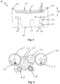
- Fig. 4 shows a movable blade 20 for a cutting device according to the invention.
- the movable blade 20 can be removed from the cutter without tools.
- the movable blade 20 has a cutting edge 21.
- the cutting edge 21 has a V-shape.
- the movable blade 20 has a recess 22. With this recess, a partial cut can be made, that is, the print medium is not completely severed in the middle and still hangs on a piece of the width of the recess. Thus, the separated part of the print medium does not fall off, but can be removed and torn off by an operator.
- the movable blade includes holes 23 which clean the fixed blade 13 as it passes.
- the movable blade 20 includes deflectors 24 on the sides of the cutting edge 21 for guiding them along the fixed blade 13.
- the direction of movement B in which the movable blade 20 moves after installation in the cutting device is indicated.
- the movable blade 20 includes two Slotted guides 26, 27, 28 over which they can be moved by drive pin of two drive gears in the direction of movement B.
- Each slotted guide has a first section 26 which extends parallel to the direction of movement B.
- the first portion 26 begins at an edge 30 which lies opposite the cutting edge 21.
- the movable blade 20 has at this edge an opening 25 into which the first portion 26 opens.
- Each slotted guide has a second section 27, which extends perpendicular to the direction of movement B of the movable blade 20 to the outside.
- the movable blade When the drive bolts are at the intersection 28 between the first gate 26 and the second section 27 of the slotted guide, the movable blade can be removed via the first section 26.
- the first portion has a first guide 31 which funnel-shaped leads into the first portion 26 and thus, together with the drive pin acts self-guiding when the movable blade 20 is introduced into the cutting device.
- the first section 26 has a second taper 32. Another recess 29 of the movable blade 20 provides space for a manual drive of the movable blade 20th
- Fig. 5 shows a gear for the cutting device.
- the transmission comprises two drive gears 40, 41, each carrying a drive pin 43, 42.
- the drive gears 40, 41 are moved via a translation of a motor with a motor gear 47 in each opposite direction.
- the drive pins 43, 42 perform a movement that is mirror-symmetrical.
- the movement of the motor gear 47 is transmitted to another gear 46, which is connected to a first ratio gear 45.
- the first ratio gear 45 drives a second ratio gear 44.
- the first and second ratio gears 45, 44 each engage a drive gear 40, 41. 41 41.
- the transmission comprises a manual gear 48, with which the further gear 46 can be moved manually, when to the Example the function of the engine has failed.
- the manual gear 48 is driven by a screwdriver.
- the screw of the manual gear is guided through the further recess 29 by the movable blade 20.
- the manual gear is no longer shown in the following drawings.
- Fig. 6 shows the gear and the moving blade 20 in a rest position. In this position, the moving blade 20 has disappeared in the housing of the cutting device.
- the drive bolts 42, 43 are in this position at the intersection 28 between the first portion 26 and the second portion 27 of the slide guides.
- Fig. 7 shows the gear and the moving blade 20 in a position when the moving blade 20 is extended or retracted along the direction of movement B.
- the drive gears 40, 41 are compared to Fig. 6 rotated by a quarter turn, so that the drive bolts 42, 43 are now on the outside of the drive gears 40, 41.
- the drive pins 42, 43 have moved along the second portion 27 of the slotted guide and the movable blade 20 is thus moved along the direction of movement B.
- Fig. 6 shows the gear and the moving blade 20 in a rest position. In this position, the moving blade 20 has disappeared in the housing of the cutting device.
- the drive bolts 42, 43 are in this position at the intersection 28 between the first portion 26 and the second portion
- FIG. 8 shows the gear and the moving blade in the cutting position or in the removal position.
- the drive gears 40, 41 are further rotated a quarter turn.
- the drive bolts 42, 43 are now at the top of the drive gears 40, 41.
- the drive bolts 42, 43 are now again at the intersection 28 between the first portion 26 and the second portion 27 of the slide guides.
- the gear wheels of the transmission are fixedly mounted in the cutting device. It can be seen that by rotation of the transmission, the drive bolts 42, 43 move along a circular path and move the moving blade 20 forward in the cutting position compared to the transmission.
- Fig. 8 shows the moving blade 20 in the cutting position.
- the cutting position is at the same time the removal position.
- the printer door 11 must be open and the moving blade 20 must remain in the removal position, while in the Operation the printer door 11 is closed and the moving blade 20 is only briefly moved to the cutting position and is immediately moved back to the rest position.
- Fig. 9 shows the side view of the moving blade 20 in the cutting device.
- the moving blade 20 is supported between a cover plate 49 of the cutter and a guide plate 50.
- the gear is mounted, the drive gears 40, 41 are mounted directly after the guide plate 50.
- the drive bolts 42, 43, pass through the guide plate 50, as will be shown below.
- the gear is held in the housing of the cutting device, as will be shown below.
- the cover plate 49 includes openings 56 for screwing to the housing.
- Fig. 10 shows the housing 12 of the cutting device.
- the housing 12 includes guide pins 51, which define the direction of movement for the moving blade 20.
- receptacles 57, 58 for the drive gears 41, 40, a receptacle 59 for a ratio gear 44, a receptacle 60 for the further gear 46 and a ratio gear 45 and a receptacle 61 for the motor gear 47.
- a receptacle 62 for shown the manual gear 48 of the transmission.
- the housing includes a receptacle 52 for the guide plate 50, which is screwed into threads 53.
- the guide plate 50 serves as a cover for the gear to hold the gears stationary.
- Fig. 11 shows the guide plate 50.
- the guide plate includes holes 54 for screwing the guide plate in the housing 12 of the cutting device.
- the guide plate 50 includes semicircular guides for the drive bolts 42, 43.
- the guide plate 50 holds the gears of the transmission in the housing 12 of the cutter and forms a guide for the moving blade 20.
Landscapes
- Life Sciences & Earth Sciences (AREA)
- Forests & Forestry (AREA)
- Engineering & Computer Science (AREA)
- Mechanical Engineering (AREA)
- Handling Of Sheets (AREA)
Abstract
Description
- Die vorliegende Erfindung betrifft einen Drucker zum Bedrucken eines Druckmediums und eine Schneidvorrichtung zum Abtrennen eines bedruckten Teils des Druckmediums.
- Die
EP 2 842 757 B1 zeigt einen Drucker und eine Schneidvorrichtung zum Abtrennen eines bedruckten Druckmediums, mit einer beweglichen Klinge, die austauschbar ist. Der Austausch erfordert eine Zerlegung der Schneidvorrichtung und einen Ausbau eines Klingen-Gleitelements. - Aufgabe der Erfindung ist es, einen Drucker mit einer Schneidvorrichtung zum Abtrennen eines bedruckten Teils des Druckmediums bereitzustellen, bei dem der Austausch einer Klinge der Schneidvorrichtung einfach und werkzeuglos auch von ungeschultem Personal vorgenommen werden kann.
- Diese Aufgabe wird durch einen Drucker nach Anspruch 1 und ein Verfahren nach Anspruch 13 gelöst.
- Erfindungsgemäß wird ein Drucker zum Bedrucken eines Druckmediums vorgeschlagen. Der Drucker umfasst eine Aufnahme für das Druckmedium. Das Druckmedium ist zu einer Rolle aufgewickelt. Der Drucker umfasst einen Druckkopf zum Bedrucken des Druckmediums während eines Druckvorgangs. Der Drucker umfasst eine Druckwalze um das Druckmedium während des Druckvorgangs am Druckkopf vorbeizuführen. Des Weiteren umfasst der Drucker eine Schneidvorrichtung zum Abtrennen eines bedruckten Teils des Druckmediums. Die Schneidvorrichtung umfasst eine feststehende Klinge und eine gegen die feststehende Klinge bewegliche Klinge. Die Schneidvorrichtung umfasst einen Antriebsmotor, mit dessen Hilfe die bewegliche Klinge aus einer Ruheposition in eine Schneidposition und zurück bewegbar ist. Eine Drehbewegung des Antriebsmotors wird mit einem Getriebe und mindestens einem Antriebsbolzen in eine lineare, vorzugsweise ungleichförmige Bewegung der beweglichen Klinge umgesetzt. Die Bewegungsbahn des mindestens einen Antriebsbolzens ist kreisförmig oder elliptisch. Der Antriebsbolzen folgt jedoch nicht einer kompletten Kreisbahn, sondern vielmehr der Bahn eines Kreisausschnitts, zum Beispiel eines Halbkreises. Die bewegliche Klinge umfasst eine Kulissenführung, in die der Antriebsbolzen eingreift. In einer Ausführungsform ist die bewegliche Klinge in der Schneidposition durch Herausziehen aus der Schneidvorrichtung entnehmbar. In einer Ausführungsform ist die bewegliche Klinge mittels des Antriebsmotors in eine Entnahmeposition bewegbar, aus der die bewegliche Klinge durch Herausziehen entnehmbar ist. In einer Ausführungsform ist die Bewegung der Druckwalze mit der Bewegung des Antriebsmotors der Schneidvorrichtung und somit mit der Bewegung der beweglichen Klinge synchronisiert, damit das Druckmedium zum richtigen Zeitpunkt abgetrennt wird.
- In einer Ausführungsform erstreckt sich die Kulissenführung in einem ersten Abschnitt von einem Rand der beweglichen Klinge, der einer Schneidkante der beweglichen Klinge gegenüberliegt, parallel zur Bewegungsrichtung der beweglichen Klinge. Das heißt, der erste Abschnitt der Kulissenführung bewegt sich vom Rand der beweglichen Klinge in Richtung deren Mitte. Die Kulissenführung erstreckt sich in eine Öffnung am Rand der beweglichen Klinge.
- In einer Ausführungsform weist die Kulissenführung einen zweiten Abschnitt auf, dessen Erstreckungsrichtung sich von der Bewegungsrichtung der beweglichen Klinge unterscheidet. In einer Ausführungsform ist die Erstreckungsrichtung des zweiten Abschnitts der Kulissenführung senkrecht zu der Bewegungsrichtung der beweglichen Klinge. In einer Ausführungsform ist der zweite Abschnitt der Kulissenführung ein linearer Abschnitt.
- In einer Ausführungsform treibt das Getriebe einen zweiten Antriebsbolzen an. Der zweite Antriebsbolzen greift in eine zweite Kulissenführung ein. In einer Ausführungsform sind die beiden Antriebsbolzen gleich groß und befinden sich während ihrer Bewegung auf gleicher Höhe im Bezug auf die Bewegungsrichtung der beweglichen Klinge.
- In einer Ausführungsform verlaufen die Bewegungsbahnen der beiden Antriebsbolzen spiegelsymmetrisch entlang einer Achse, die parallel zu der Bewegungsrichtung der beweglichen Klinge ist. In einer Ausführungsform sind die beiden Kulissenführungen spiegelsymmetrisch zu dieser Achse in der beweglichen Klinge angeordnet.
- In einer Ausführungsform umfasst der Drucker ein Druckergehäuse und eine Druckertür. Die Druckertür kann eine Rotationsbewegung zum Öffnen der Druckertür ausführen. Die bewegliche Klinge ist im Druckergehäuse angeordnet und die feste Klinge ist in der Druckertür angeordnet. In einer Ausführungsform ist die bewegliche Klinge in der Druckertür angeordnet und die feste Klinge ist im Druckergehäuse angeordnet.
- In einer Ausführungsform ist die bewegliche Klinge einstückig ausgeführt. In einer Ausführungsform gleitet die bewegliche Klinge in einer Führung der Schneidvorrichtung, wobei die Bewegungsrichtung der beweglichen Klinge durch die Führung auf eine Richtung, die Bewegungsrichtung, begrenzt ist. Darunter ist zu verstehen, dass die Klinge in der Bewegungsrichtung sowohl vor als auch zurückbewegt werden kann.
- In einer Ausführungsform ist eine Schneidkante der beweglichen Klinge in einer V-Form ausgebildet. Am Knickpunkt der V-Form, der Vorzugsweise in der Mitte der beweglichen Klinge angeordnet ist, weist die bewegliche Klinge eine Ausnehmung auf.
- In einer Ausführungsform ist das Getriebe derart gestaltet, dass mittels einer Drehbewegung des Antriebsmotors der mindestens eine Antriebsbolzen in eine Entnahmeposition gebracht werden kann. Der mindestens eine Antriebsbolzen greift in der Entnahmeposition in den ersten Abschnitt der Kulissenführung ein. In einer Ausführungsform ist die Entnahmeposition gleich der Schneidposition. Allerdings bleibt die Klinge in der Entnahmeposition stehen, das heißt der mindestens eine Antriebsbolzen wird durch den Antriebsmotor derart bewegt, dass die bewegliche Klinge in der Entnahmeposition stehen bleibt. Beim normalen Schneidvorgang wird der mindestens eine Antriebsbolzen durch den Antriebsmotor derart bewegt, dass die bewegliche Klinge in die Schneidposition gebracht wird und sofort nach dem Schneidvorgang wieder in die Ruheposition zurückbewegt wird. Auch wenn die Entnahmeposition und die Schneidposition identisch sind, was die geometrische Position des mindestens einen Antriebsbolzens betrifft, so unterscheidet sich die Entnahmeposition dadurch, dass die bewegliche Klinge nicht sofort wieder zurückgeführt wird. Außerdem kann die bewegliche Klinge in die Entnahmeposition gebracht werden, wenn die Druckertür geöffnet ist. Ein Schneidvorgang ist hingegen nicht möglich, wenn die Druckertür geöffnet ist.
- In einer Ausführungsform umfasst der Drucker einen Sensor zum Überwachen der Druckertür. Die Bewegung des mindestens einen Antriebsbolzens in die Entnahmeposition durch den Antriebsmotor ist nur möglich, wenn die Druckertür geöffnet ist. Nur dann kann ein Bediener die bewegliche Klinge greifen und aus der Schneidvorrichtung herausziehen, um zum Beispiel die bewegliche Klinge zu wechseln, wenn diese verschlissen ist.
- In einer Ausführungsform wird die bewegliche Klinge zwischen einer Abdeckplatte und einer Führungsplatte geführt. Die Führungsplatte und die Abdeckplatte bestimmen die laterale Position der beweglichen Klinge in der Schneidvorrichtung und im Drucker. Die Abdeckplatte bildet eine Außenwand der Schneidvorrichtung und die Führungsplatte bildet eine Wand innerhalb der Schneidvorrichtung. In einer Ausführungsform umfasst die Führungsplatte zwei halbkreisförmige Ausnehmungen, in denen die Antriebsbolzen bewegt werden und durch diese greifen die Antriebsbolzen in die Kulissenführung der beweglichen Klinge ein. In einer Ausführungsform ist die Bewegungsrichtung der beweglichen Klinge durch eine seitliche Führung definiert. Die seitliche Führung besteht in einer Ausführungsform aus Führungsstiften, die zwischen Abdeckplatte und Führungsplatte verlaufen und die Bewegungsrichtung der beweglichen Klinge vorgeben.
- In einer Ausführungsform umfasst das Getriebe zwei gleiche Antriebszahnräder. Gleich heißt, die Antriebszahnräder haben den gleichen Durchmesser, die gleiche Anzahl Zähne und die Antriebsbolzen befinden sich in der gleichen Entfernung vom Mittelpunkt. Die Antriebszahnräder haltern jeweils einen Antriebsbolzen und sind symmetrisch zur Bewegungsrichtung der beweglichen Klinge angeordnet. Das Getriebe umfasst zwei gleiche Übersetzungszahnräder, die wechselseitig ineinander eingreifen. Jedes Übersetzungszahnrad greift in ein Antriebszahnrad ein. Der Antriebsmotor treibt ein Übersetzungszahnrad mittels eines Motorzahnrads an. Durch diese Abordnung bewegen sich die Antriebsbolzen auf den Antriebszahnrädern symmetrisch zu einer Achse parallel zur Bewegungsrichtung der beweglichen Klinge. Das heißt, die Antriebszahnräder bewegen sich in entgegengesetzte Richtungen.
- Erfindungsgemäß wird ein Verfahren zum Wechseln einer beweglichen Klinge einer Schneidvorrichtung eines Druckers vorgeschlagen. Das Verfahren umfasst den Schritt des Empfangens einer Messertauschanweisung an einer Eingabevorrichtung des Druckers und das Überführen des Druckers in einen Servicebetrieb. Das Verfahren umfasst den Schritt des Drehens eines Antriebsmotors einer Schneidevorrichtung in eine Position, in der die Antriebsbolzen in einer Entnahmeposition sind. Das Verfahren umfasst den Schritt des Empfangens einer Anweisung, dass die Schneidvorrichtung wieder in einen Druckbetrieb übergehen soll. Diese Anweisung wird in einer Ausführungsform über die Eingabevorrichtung empfangen, wenn zum Beispiel ein Bediener den Klingenwechsel vollzogen hat und dies an der Eingabevorrichtung eingibt. In einer Ausführungsform wird diese Anweisung von einem Sensor empfangen, der einen vollzogenen Klingenwechsel detektiert. Das Verfahren umfasst den Schritt des Drehens des Antriebsmotors in eine Position, in der die Antriebsbolzen in der Ruheposition sind. Somit wird die gewechselte bewegliche Klinge in die Schneidvorrichtung eingezogen. Das Verfahren umfasst den Schritt des Überführens des Druckers in den Druckbetrieb.
- In einer Ausführungsform umfasst das Verfahren vor dem Drehen des Antriebsmotors in eine Position, in der die Antriebsbolzen in der Entnahmeposition sind, den Schritt des Prüfens mittels eines Sensors ob die Druckertür geöffnet ist.
- In einer Ausführungsform umfasst das Verfahren vor dem Überführen des Druckers in den Druckbetrieb den Schritt des Prüfens mittels eines Sensors ob die Druckertür geschlossen ist.
- Einige Ausführungsformen der Erfindung sind in den Zeichnungen beispielhaft gezeigt und nachfolgend beschrieben. Es zeigen, jeweils in schematischer Darstellung:
- Fig. 1
- eine Waage mit Drucker,
- Fig. 2
- einen Drucker für eine Waage mit geschlossener Druckertür,
- Fig. 3
- einen Drucker für eine Waage mit geöffneter Druckertür,
- Fig. 4
- eine bewegliche Klinge für eine erfindungsgemäße Schneidvorrichtung,
- Fig. 5
- ein Getriebe für eine erfindungsgemäße Schneidvorrichtung,
- Fig. 6
- das Getriebe und die bewegliche Klinge in einer Ruheposition,
- Fig. 7
- das Getriebe und die bewegliche Klinge in einer Position zwischen einer Ruheposition und einer Schneidposition,
- Fig. 8
- das Getriebe und die bewegliche Klinge in einer Schneidposition,
- Fig. 9
- eine erfindungsgemäße Schneidvorrichtung in einer seitlichen Ansicht,
- Fig. 10
- ein Gehäuse einer erfindungsgemäßen Schneidvorrichtung,
- Fig. 11
- eine Führungsplatte einer erfindungsgemäßen Schneidvorrichtung.
-
Fig. 1 zeigt schematisch eine Waage 1 mit Drucker 6. Die Waage 1 umfasst ein Gehäuse 2 und eine Lastplatte 3 zum Auflegen von zu wiegenden Waren. Im Gehäuse 2 ist eine Wiegevorrichtung angebracht, die das Gewicht der auf der Lastplatte 3 aufgelegten Waren bestimmt. Die Waage 1 umfasst ein Stativ 4 an dem der Drucker 6 befestigt ist und an dem des Weiteren eine Eingabevorrichtung 5 zum Bedienen der Waage 1 angebracht ist. Über die Eingabevorrichtung 5 können auch Anweisungen für den Drucker 6 eingegeben werden. Der Drucker 6 umfasst eine Ausgabeöffnung 7, hinter der sich eine Schneidvorrichtung (nicht gezeigt) zum Abtrennen eines bedruckten Teils eines Druckmediums befindet. -
Fig. 2 zeigt einen Schnitt durch einen erfindungsgemäßen Drucker 6, bei dem die Druckertür 11 geschlossen ist. Der Drucker kann in eine Waage nachFig. 1 eingebaut sein. Alternativ kann der Drucker 6 auch im Gehäuse einer Waage unterhalb der Lastplatte eingebaut sein.Fig. 3 zeigt den Drucker 6, wenn die Druckertür 11 geöffnet ist und sich der Drucker 6 im Servicebetrieb befindet. Der Drucker 6 umfasst eine Aufnahme 10 für ein zu einer Rolle aufgewickeltes Druckmedium. Die Druckertür 11 ist an einem Scharnier oder einer Führung gelagert und kann durch den Bediener entlang einer Bewegungsrichtung 17 geöffnet und geschlossen werden. Der Drucker 6 umfasst eine Druckwalze 14 um das Druckmedium während eines Druckvorgangs an einem Druckkopf 15 vorbeizuführen, der das Druckmedium bedruckt. Der Drucker 6 umfasst eine Schneidvorrichtung 12, 13 zum Abtrennen des Druckmediums. Die Schneidvorrichtung umfasst ein Gehäuse 12, in dem eine bewegliche Klinge gelagert ist und eine feste Klinge 13. Die feste Klinge 13 ist in der Druckertür 11 angebracht. Das Gehäuse 12 der Schneidvorrichtung ist im Gehäuse des Druckers 6 angebracht. Zwischen Gehäuse des Druckers 6 und Druckertür 11 befindet sich eine Ausgabeöffnung 7, durch die der bedruckte Teil des Druckmediums ausgegeben wird. Der Drucker 6 umfasst weiter einen Sensor 16, der detektiert ob die Druckertür 11 geschlossen oder geöffnet ist. -
Fig. 4 zeigt eine bewegliche Klinge 20 für eine erfindungsgemäße Schneidvorrichtung. Die bewegliche Klinge 20 kann werkzeuglos aus der Schneidvorrichtung entfernt werden. Die bewegliche Klinge 20 weist eine Schneidkante 21 auf. Die Schneidkante 21 hat eine V-Form. Im Knickpunkt der V-Form in der Mitte der Schneidkante 21 weist die bewegliche Klinge 20 eine Ausnehmung 22 auf. Mit dieser Ausnehmung kann auch ein Teilschnitt erfolgen, das heißt, das Druckmedium wird in der Mitte nicht ganz durchtrennt und hängt an einem Stück von der Breite der Ausnehmung noch zusammen. So fällt der abgetrennte Teil des Druckmediums nicht ab, sondern kann durch einen Bediener abgenommen und abgerissen werden. Hinter der Schneidkante 21 umfasst die bewegliche Klinge Löcher 23, die die feste Klinge 13 beim vorbeibewegen reinigen. Die bewegliche Klinge 20 umfasst an den Seiten der Schneidkante 21 Abweiser 24, um sie an der festen Klinge 13 entlang zu führen. Die Bewegungsrichtung B in der sich die bewegliche Klinge 20 nach dem Einbau in die Schneidvorrichtung bewegt ist angedeutet. Die bewegliche Klinge 20 umfasst zwei Kulissenführungen 26, 27, 28 über die sie durch Antriebsbolzen von zwei Antriebszahnrädern in der Bewegungsrichtung B bewegt werden kann. Jede Kulissenführung weist einen ersten Abschnitt 26 auf, der sich parallel zur Bewegungsrichtung B erstreckt. Der erste Abschnitt 26 beginnt an einer Kante 30, die der Schneidkante 21 gegenüber liegt. Die bewegliche Klinge 20 hat an dieser Kante eine Öffnung 25, in die der erste Abschnitt 26 mündet. Jede Kulissenführung weist einen zweiten Abschnitt 27 auf, der sich senkrecht zur Bewegungsrichtung B der beweglichen Klinge 20 nach außen erstreckt. Wenn die Antriebsbolzen am Schnittpunkt 28 zwischen erstem Anschnitt 26 und zweiten Abschnitt 27 der Kulissenführung stehen, kann die bewegliche Klinge über den ersten Abschnitt 26 entnommen werden. Der erste Abschnitt weist eine erste Führung 31 auf, die Trichterförmig in den ersten Abschnitt 26 führt und somit zusammen mit den Antriebsbolzen selbstführend wirkt, wenn die bewegliche Klinge 20 in die Schneidvorrichtung eingebracht wird. Der erste Abschnitt 26 weist eine zweite Verjüngung 32 auf. Eine weitere Ausnehmung 29 der beweglichen Klinge 20 schafft Bauraum für einen manuellen Antrieb der beweglichen Klinge 20. -
Fig. 5 zeigt ein Getriebe für die Schneidvorrichtung. Das Getriebe umfasst zwei Antriebszahnräder 40, 41, die jeweils einen Antriebsbolzen 43, 42 tragen. Die Antriebszahnräder 40, 41 werden über eine Übersetzung von einem Motor mit einem Motorzahnrad 47 in jeweils gegenläufiger Richtung bewegt. Somit führen die Antriebsbolzen 43, 42 eine Bewegung aus, die spiegelsymmetrisch ist. Die Bewegung des Motorzahnrads 47 wird auf ein weiteres Zahnrad 46 übertragen, das mit einem ersten Übersetzungszahnrad 45 verbunden ist. Das erste Übersetzungszahnrad 45 treibt ein zweites Übersetzungszahnrad 44 an. Das erste und das zweite Übersetzungszahnrad 45, 44 greifen jeweils in ein Antriebszahnrad 40, 41 ein. Über das erste und das zweite Übersetzungszahnrad 45, 44 entsteht die gegenläufige Bewegung der Antriebszahnräder 40. 41. Optional umfasst das Getriebe ein manuelles Zahnrad 48, mit dem das weitere Zahnrad 46 manuell bewegt werden kann, wenn zum Beispiel die Funktion des Motors ausgefallen ist. Dafür wird das manuelle Zahnrad 48 mit einem Schraubendreher angetrieben. Die Schaube des manuellen Zahnrads ist durch die weitere Ausnehmung 29 durch das bewegliche Messer 20 geführt. Zur Vereinfachung wird das manuelle Zahnrad in den folgenden Zeichnungen nicht mehr gezeigt. -
Fig. 6 zeigt das Getriebe und die bewegte Klinge 20 in einer Ruheposition. In dieser Position ist die bewegte Klinge 20 im Gehäuse der Schneidvorrichtung verschwunden. Die Antriebsbolzen 42, 43 befinden sich in dieser Position im Schnittpunkt 28 zwischen dem ersten Abschnitt 26 und dem zweiten Abschnitt 27 der Kulissenführungen.Fig. 7 zeigt das Getriebe und die bewegte Klinge 20 in einer Position, wenn die bewegte Klinge 20 entlang der Bewegungsrichtung B ausgefahren oder eingefahren wird. Die Antriebszahnräder 40, 41 sind im Vergleich zuFig. 6 um eine Viertelumdrehung verdreht, so dass die Antriebsbolzen 42, 43 jetzt auf der Außenseite der Antriebszahnräder 40, 41 sind. Die Antriebsbolzen 42, 43 haben sich entlang des zweiten Abschnitts 27 der Kulissenführung bewegt und die bewegliche Klinge 20 so entlang der Bewegungsrichtung B bewegt.Fig. 8 zeigt das Getriebe und die bewegte Klinge in der Schneidposition bzw. in der Entnahmeposition. Die Antriebszahnräder 40, 41 sind noch einmal eine Viertelumdrehung weitergedreht. Die Antriebsbolzen 42, 43 sind nun oben an den Antriebszahnrädern 40, 41. Die Antriebsbolzen 42, 43 sind nun wieder am Schnittpunkt 28 zwischen dem ersten Abschnitt 26 und dem zweiten Abschnitt 27 der Kulissenführungen. In denFiguren 6-8 sind die Zahnräder des Getriebes ortsfest in der Schneidvorrichtung angebracht. Es ist zu sehen, dass durch eine Drehung des Getriebes die Antriebsbolzen 42, 43 sich entlang einer Kreisbahn bewegen und die bewegte Klinge 20 im Vergleich zum Getriebe nach vorne in die Schneidposition bewegen.Fig. 8 zeigt die bewegte Klinge 20 in der Schneidposition. Die Schneidposition ist gleichzeitig auch die Entnahmeposition. Jedoch muss zum Klingenwechsel die Druckertür 11 geöffnet sein und die bewegte Klinge 20 in der Entnahmeposition verbleiben, während im Betrieb die Druckertür 11 geschlossen ist und die bewegte Klinge 20 nur kurz in die Schneidposition bewegt wird und sogleich wieder zurück in die Ruheposition zurückbewegt wird. -
Fig. 9 zeigt die Seitenansicht der bewegten Klinge 20 in der Schneidvorrichtung. Die bewegte Klinge 20 ist zwischen einer Abdeckplatte 49 der Schneidvorrichtung und einer Führungsplatte 50 gehaltert. Somit ist nur eine Bewegung der bewegten Klinge 20 in der Bewegungsrichtung B möglich. Hinter der Führungsplatte 50 ist das Getriebe angebracht, wobei die Antriebszahnräder 40, 41 direkt nach der Führungsplatte 50 angebracht sind. Die Antriebsbolzen 42, 43, greifen durch die Führungsplatte 50 durch, wie im Folgenden noch gezeigt ist. Das Getriebe ist im Gehäuse der Schneidvorrichtung gehaltert, wie im Folgenden noch gezeigt ist. Die Abdeckplatte 49 umfasst Öffnungen 56 zur Verschraubung mit dem Gehäuse. -
Fig. 10 zeigt das Gehäuse 12 der Schneidvorrichtung. Das Gehäuse 12 umfasst Führungsstifte 51, die die Bewegungsrichtung für die bewegte Klinge 20 vorgeben. Im Gehäuse 20 sind Aufnahmen 57, 58 für die Antriebszahnräder 41, 40, eine Aufnahme 59 für ein Übersetzungszahnrad 44, eine Aufnahme 60 für das weitere Zahnrad 46 und ein Übersetzungszahnrad 45 sowie eine Aufnahme 61 für das Motorzahnrad 47. Außerdem ist eine Aufnahme 62 für das manuelle Zahnrad 48 des Getriebes gezeigt. Das Gehäuse umfasst eine Aufnahme 52 für die Führungsplatte 50, die in Gewinden 53 verschraubt wird. Die Führungsplatte 50 dient als Abdeckung für das Getriebe um die Zahnräder ortsfest zu halten. -
Fig. 11 zeigt die Führungsplatte 50. Die Führungsplatte umfasst Löcher 54 zum Verschrauben der Führungsplatte im Gehäuse 12 der Schneidvorrichtung. Die Führungsplatte 50 umfasst halbkreisförmige Führungen für die Antriebsbolzen 42, 43. Die Führungsplatte 50 hält die Zahnräder des Getriebes im Gehäuse 12 der Schneidvorrichtung und bildet eine Führung für die bewegte Klinge 20.
Claims (15)
- Drucker zum Bedrucken eines Druckmediums
mit einer Aufnahme für das zu einer Rolle aufgewickelte Druckmedium,
einem Druckkopf (15) zum Bedrucken des Druckmediums während eines Druckvorgangs,
einer Druckwalze (14) um das Druckmedium während des Druckvorgangs am Druckkopf (15) vorbeizuführen, und
einer Schneidvorrichtung (12, 13) zum Abtrennen eines bedruckten Teils des Druckmediums, wobei die Schneidvorrichtung eine feststehende Klinge (13) und eine gegen die feststehende Klinge (13) bewegliche Klinge (20) umfasst, wobei die Schneidvorrichtung einen Antriebsmotor umfasst, mittels dessen die bewegliche Klinge (20) aus einer Ruheposition in eine Schneidposition und zurück bewegbar ist,
dadurch gekennzeichnet,
dass eine Drehbewegung des Antriebsmotors mit einem Getriebe (40, 41, 44, 45, 46) und mindestens einem Antriebsbolzen (42, 42) in eine lineare Bewegung der beweglichen Klinge (20) umgesetzt wird, wobei die Bewegungsbahn des mindestens einen Antriebsbolzens (42, 43) kreisförmig oder elliptisch ist und wobei die bewegliche Klinge (20) eine Kulissenführung (26, 27, 28) umfasst, in die der Antriebsbolzen (42, 43) eingreift. - Drucker nach Anspruch 1, dadurch gekennzeichnet, dass sich die Kulissenführung in einem ersten Abschnitt von einem Rand der beweglichen Klinge, der einer Schneidkante der beweglichen Klinge gegenüberliegt, parallel zur Bewegungsrichtung der beweglichen Klinge erstreckt.
- Drucker nach Anspruch 1 oder 2, dadurch gekennzeichnet, dass die Kulissenführung einen zweiten Abschnitt aufweist, dessen Erstreckungsrichtung sich von der Bewegungsrichtung der beweglichen Klinge unterscheidet und dessen Erstreckungsrichtung vorzugsweise senkrecht zu der Bewegungsrichtung der beweglichen Klinge ist.
- Drucker nach einem der Ansprüche 1 bis 3, dadurch gekennzeichnet, dass das Getriebe einen zweiten Antriebsbolzen antreibt, wobei der zweite Antriebsbolzen in eine zweite Kulissenführung eingreift.
- Drucker nach Anspruch 4, dadurch gekennzeichnet, dass die Bewegungsbahnen der beiden Antriebsbolzen spiegelsymmetrisch entlang einer Achse verlaufen, die parallel zu der Bewegungsrichtung der beweglichen Klinge ist, und dass die beiden Kulissenführungen spiegelsymmetrisch zu dieser Achse in der beweglichen Klinge angeordnet sind.
- Drucker nach einem der Ansprüche 1 bis 5, dadurch gekennzeichnet,
dass der Drucker ein Druckergehäuse und eine Druckertür umfasst, wobei die Druckertür eine Rotationsbewegung zum Öffnen der Druckertür ausführen kann, und dass die bewegliche Klinge im Druckergehäuse und die feste Klinge in der Druckertür angeordnet ist, oder dass die bewegliche Klinge in der Druckertür und die feste Klinge im Druckergehäuse angeordnet ist. - Drucker nach einem der Ansprüche 1 bis 6, dadurch gekennzeichnet,
dass das die bewegliche Klinge einstückig aufgeführt ist und in einer Führung der Schneidvorrichtung gleitet, wobei die Bewegungsrichtung der beweglichen Klinge durch die Führung auf eine Richtung begrenzt ist. - Drucker nach einem der Ansprüche 1 bis 7, dadurch gekennzeichnet,
dass eine Schneidkante der bewegliche Klinge in einer V-Form ausgebildet ist und am Knickpunkt der V-Form eine Ausnehmung aufweist. - Drucker nach einem der Ansprüche 2 bis 8, dadurch gekennzeichnet,
dass das Getriebe derart gestaltet ist, dass mittels einer Drehbewegung des Antriebsmotors der mindestens eine Antriebsbolzen in eine Entnahmeposition gebracht werden kann, wobei der mindestens eine Antriebsbolzen in der Entnahmeposition in den ersten Abschnitt der Kulissenführung eingreift. - Drucker nach Anspruch 8, dadurch gekennzeichnet,
dass der Drucker einen Sensor zum Überwachen der Druckertür umfasst und die Bewegung des mindestens einen Antriebsbolzens in die Entnahmeposition durch den Antriebsmotor nur möglich ist, wenn die Druckertür geöffnet ist. - Drucker nach einem der Ansprüche 1 bis 10, dadurch gekennzeichnet,
dass die bewegliche Klinge zwischen einer Abdeckplatte und einer Führungsplatte geführt wird, wobei die Führungsplatte und die Abdeckplatte die laterale Position der beweglichen Klinge im Drucker bestimmen und dass die Bewegungsrichtung der beweglichen Klinge durch eine seitliche Führung definiert ist. - Drucker nach einem der Ansprüche 1 bis 11, dadurch gekennzeichnet,
dass das Getriebe zwei gleiche Antriebszahnrädern umfasst, die jeweils einen Antriebsbolzen haltern und symmetrisch zur Bewegungsrichtung der beweglichen Klinge angeordnet sind, und dass das Getriebe zwei gleiche Übersetzungszahnräder umfasst, die wechselseitig ineinander eingreifen und wobei jedes Übersetzungszahnrad in ein Antriebszahnrad eingreift, und wobei der Antriebsmotor ein Übersetzungszahnrad mittels eines Motorzahnrads antreibt. - Verfahren zum Wechseln einer beweglichen Klinge einer Schneidvorrichtung eines Druckers dadurch gekennzeichnet, dass es folgende Schritte umfasst:- empfangen einer Messertauschanweisung an einer Eingabevorrichtung und überführen des Druckers in einen Servicebetrieb,- drehen eines Antriebsmotors einer Schneidevorrichtung in eine Position, in der die Antriebsbolzen in einer Entnahmeposition sind,- empfangen einer Anweisung, dass die Schneidvorrichtung wieder in einen Druckbetrieb übergehen soll,- drehen des Antriebsmotors in eine Position, in der die Antriebsbolzen in der Ruheposition sind, und- überführen des Druckers in den Druckbetrieb.
- Verfahren nach Anspruch 13, dadurch gekennzeichnet, dass vor dem Drehen des Antriebsmotors in eine Position, in der die Antriebsbolzen in der Entnahmeposition sind, das Verfahren einen Schritt des Prüfens eines Sensors ob die Druckertür geöffnet ist umfasst.
- Verfahren nach Anspruch 13 oder 14, dadurch gekennzeichnet,
dass vor dem Überführen des Druckers in den Druckbetrieb das Verfahren einen Schritt des Prüfens eines Sensors ob die Druckertür geschlossen ist umfasst.
Priority Applications (2)
| Application Number | Priority Date | Filing Date | Title |
|---|---|---|---|
| EP17211267.4A EP3505355B1 (de) | 2017-12-31 | 2017-12-31 | Abschneidevorrichtung fuer endlosetiketten |
| US16/211,264 US10717624B2 (en) | 2017-12-31 | 2018-12-06 | Cutting device for continuous labels |
Applications Claiming Priority (1)
| Application Number | Priority Date | Filing Date | Title |
|---|---|---|---|
| EP17211267.4A EP3505355B1 (de) | 2017-12-31 | 2017-12-31 | Abschneidevorrichtung fuer endlosetiketten |
Publications (2)
| Publication Number | Publication Date |
|---|---|
| EP3505355A1 true EP3505355A1 (de) | 2019-07-03 |
| EP3505355B1 EP3505355B1 (de) | 2022-01-26 |
Family
ID=60888301
Family Applications (1)
| Application Number | Title | Priority Date | Filing Date |
|---|---|---|---|
| EP17211267.4A Active EP3505355B1 (de) | 2017-12-31 | 2017-12-31 | Abschneidevorrichtung fuer endlosetiketten |
Country Status (2)
| Country | Link |
|---|---|
| US (1) | US10717624B2 (de) |
| EP (1) | EP3505355B1 (de) |
Cited By (3)
| Publication number | Priority date | Publication date | Assignee | Title |
|---|---|---|---|---|
| EP3936446A1 (de) * | 2020-07-10 | 2022-01-12 | Bizerba SE & Co. KG | Verfahren zum abtrennen von etiketten |
| EP3967503A1 (de) * | 2020-09-11 | 2022-03-16 | Bizerba SE & Co. KG | Etikettendrucker |
| US12129142B2 (en) | 2020-07-10 | 2024-10-29 | Bizerba SE & Co. KG | Cutter for self-adhesive linerless endless tape labels |
Citations (3)
| Publication number | Priority date | Publication date | Assignee | Title |
|---|---|---|---|---|
| US6109154A (en) * | 1997-03-18 | 2000-08-29 | Fujitsu Takamisawa Component Limited | Sheet-cutter having motor driven push cutter |
| US20100086340A1 (en) * | 2008-10-08 | 2010-04-08 | Brother Kogyo Kabushiki Kaisha | Cutting mechanism for printing apparatus, and printing apparatus including the same |
| EP2842757B1 (de) | 2013-08-28 | 2017-04-19 | Fujitsu Component Limited | Drucker |
Family Cites Families (6)
| Publication number | Priority date | Publication date | Assignee | Title |
|---|---|---|---|---|
| US4312597A (en) * | 1977-11-06 | 1982-01-26 | Copal Company Limited | Printer |
| JP3800891B2 (ja) * | 1999-10-29 | 2006-07-26 | スター精密株式会社 | プリンタ |
| JP3730153B2 (ja) * | 2001-10-18 | 2005-12-21 | セイコーインスツル株式会社 | プリンタのカッター装置 |
| JP4455091B2 (ja) * | 2004-02-20 | 2010-04-21 | スター精密株式会社 | 用紙カッター |
| JP4715457B2 (ja) * | 2005-11-16 | 2011-07-06 | セイコーエプソン株式会社 | シート切断装置、およびこれを備えた印刷装置 |
| KR101282299B1 (ko) * | 2012-12-21 | 2013-07-10 | 이일복 | 프린터의 커터 |
-
2017
- 2017-12-31 EP EP17211267.4A patent/EP3505355B1/de active Active
-
2018
- 2018-12-06 US US16/211,264 patent/US10717624B2/en active Active
Patent Citations (3)
| Publication number | Priority date | Publication date | Assignee | Title |
|---|---|---|---|---|
| US6109154A (en) * | 1997-03-18 | 2000-08-29 | Fujitsu Takamisawa Component Limited | Sheet-cutter having motor driven push cutter |
| US20100086340A1 (en) * | 2008-10-08 | 2010-04-08 | Brother Kogyo Kabushiki Kaisha | Cutting mechanism for printing apparatus, and printing apparatus including the same |
| EP2842757B1 (de) | 2013-08-28 | 2017-04-19 | Fujitsu Component Limited | Drucker |
Cited By (6)
| Publication number | Priority date | Publication date | Assignee | Title |
|---|---|---|---|---|
| EP3936446A1 (de) * | 2020-07-10 | 2022-01-12 | Bizerba SE & Co. KG | Verfahren zum abtrennen von etiketten |
| US11685134B2 (en) | 2020-07-10 | 2023-06-27 | Bizerba SE & Co. KG | Method of cutting off labels |
| US12129142B2 (en) | 2020-07-10 | 2024-10-29 | Bizerba SE & Co. KG | Cutter for self-adhesive linerless endless tape labels |
| EP3967503A1 (de) * | 2020-09-11 | 2022-03-16 | Bizerba SE & Co. KG | Etikettendrucker |
| EP4105030A1 (de) * | 2020-09-11 | 2022-12-21 | Bizerba SE & Co. KG | Etikettendrucker |
| US11794497B2 (en) | 2020-09-11 | 2023-10-24 | Bizerba SE & Co. KG | Label printer |
Also Published As
| Publication number | Publication date |
|---|---|
| EP3505355B1 (de) | 2022-01-26 |
| US20190202654A1 (en) | 2019-07-04 |
| US10717624B2 (en) | 2020-07-21 |
Similar Documents
| Publication | Publication Date | Title |
|---|---|---|
| DE68920497T3 (de) | Apparat zum stufenweisen Abisolieren von Draht. | |
| AT514929B1 (de) | Werkzeugrüstsystem für Biegepresse | |
| DE2701068A1 (de) | Schlitzvorrichtung fuer bahnenfoermiges material | |
| DE1927769B2 (de) | Vorrichtung zum Herstellen von Streifen durch in Längsrichtung erfolgendes Schlitzen einer Papierbahn | |
| DE112017004840T5 (de) | Rotative Abisoliervorrichtung | |
| DE602005000347T2 (de) | Kraftübertragungsvorrichtung und diese enthaltendes Zufuhrgerät für plattenförmiges Material | |
| DE102007012777A1 (de) | Verfahren und Vorrichtung zum gesteuerten Verschließen wenigstens eines Clips um einen füllgutfreien Zopfabschnitt zwischen zwei mit einer Hülle umschlossenen Füllgutabschnitten | |
| EP3505355A1 (de) | Abschneidevorrichtung fuer endlosetiketten | |
| EP1330324A1 (de) | Kompakte kreismesserschere | |
| EP3566985B1 (de) | Trayabstapelvorrichtung mit entlastungseinrichtung | |
| EP1415944B1 (de) | Vorrichtung zum Verstellen von Anpressrollen und/oder Schneidmesser an Falzapparaten | |
| EP2964550B1 (de) | Vorrichtung zur positionierung und/oder ausrichtung ein oder mehrerer verstellbarer leitkomponenten zur führung von artikeln in einem transportsystem | |
| EP0640547A1 (de) | Drehbare Stapelkammer in einem Kreuzleger für Druckprodukte | |
| DE19953908A1 (de) | Hochgeschwindigkeitsschere zum Querteilen von Walzband | |
| DE102010007917B4 (de) | Handbetätigtes Werkzeug | |
| EP3560668A1 (de) | Vorrichtung und verfahren zum schneiden eines produkts, insbesondere aus süsswarenmasse | |
| DE1710632C3 (de) | Vorrichtung zum Fibrillieren von unter Spannung stehenden Folienbandern oder Faden | |
| DE1013664B (de) | Vorrichtung zum Einstellen der Anlegemarken in einer Bogen bearbeitenden Maschine, wie Druckmaschine und Presse zum Schneiden von Papier oder Pappe | |
| EP1799457B1 (de) | Vorrichtung mit mehreren walzen | |
| DE102020107945B4 (de) | Umreifungsvorrichtung mit Einrichtung zum Drehen eines Packstückes | |
| DE10162446A1 (de) | Schneidwerk mit einem spiralförmigen Mechanismus zum Verändern der Schnittlänge und Verfahren zum Betreiben des Schneidwerks | |
| EP4438254A2 (de) | Vorrichtung zum zuschneiden von verpackungen | |
| DE4411905C2 (de) | Verfahren und Vorrichtung zur Probenahme von einem Materialband-Bund | |
| EP1184314A2 (de) | Vorrichtung zum Führen von Signaturen, insbesondere im Bereich eines Auslauf-Zwickels einer Schneidzylinderanordnung in einem Falzapparat einer Rotationsdruckmaschine | |
| DE4202186A1 (de) | Schneidapparat |
Legal Events
| Date | Code | Title | Description |
|---|---|---|---|
| PUAI | Public reference made under article 153(3) epc to a published international application that has entered the european phase |
Free format text: ORIGINAL CODE: 0009012 |
|
| STAA | Information on the status of an ep patent application or granted ep patent |
Free format text: STATUS: THE APPLICATION HAS BEEN PUBLISHED |
|
| AK | Designated contracting states |
Kind code of ref document: A1 Designated state(s): AL AT BE BG CH CY CZ DE DK EE ES FI FR GB GR HR HU IE IS IT LI LT LU LV MC MK MT NL NO PL PT RO RS SE SI SK SM TR |
|
| AX | Request for extension of the european patent |
Extension state: BA ME |
|
| STAA | Information on the status of an ep patent application or granted ep patent |
Free format text: STATUS: REQUEST FOR EXAMINATION WAS MADE |
|
| 17P | Request for examination filed |
Effective date: 20191219 |
|
| RBV | Designated contracting states (corrected) |
Designated state(s): AL AT BE BG CH CY CZ DE DK EE ES FI FR GB GR HR HU IE IS IT LI LT LU LV MC MK MT NL NO PL PT RO RS SE SI SK SM TR |
|
| GRAP | Despatch of communication of intention to grant a patent |
Free format text: ORIGINAL CODE: EPIDOSNIGR1 |
|
| STAA | Information on the status of an ep patent application or granted ep patent |
Free format text: STATUS: GRANT OF PATENT IS INTENDED |
|
| INTG | Intention to grant announced |
Effective date: 20211021 |
|
| GRAS | Grant fee paid |
Free format text: ORIGINAL CODE: EPIDOSNIGR3 |
|
| GRAA | (expected) grant |
Free format text: ORIGINAL CODE: 0009210 |
|
| STAA | Information on the status of an ep patent application or granted ep patent |
Free format text: STATUS: THE PATENT HAS BEEN GRANTED |
|
| AK | Designated contracting states |
Kind code of ref document: B1 Designated state(s): AL AT BE BG CH CY CZ DE DK EE ES FI FR GB GR HR HU IE IS IT LI LT LU LV MC MK MT NL NO PL PT RO RS SE SI SK SM TR |
|
| REG | Reference to a national code |
Ref country code: GB Ref legal event code: FG4D Free format text: NOT ENGLISH |
|
| REG | Reference to a national code |
Ref country code: CH Ref legal event code: EP |
|
| REG | Reference to a national code |
Ref country code: AT Ref legal event code: REF Ref document number: 1464975 Country of ref document: AT Kind code of ref document: T Effective date: 20220215 |
|
| REG | Reference to a national code |
Ref country code: IE Ref legal event code: FG4D Free format text: LANGUAGE OF EP DOCUMENT: GERMAN |
|
| REG | Reference to a national code |
Ref country code: DE Ref legal event code: R096 Ref document number: 502017012512 Country of ref document: DE |
|
| REG | Reference to a national code |
Ref country code: LT Ref legal event code: MG9D |
|
| REG | Reference to a national code |
Ref country code: NL Ref legal event code: MP Effective date: 20220126 |
|
| PG25 | Lapsed in a contracting state [announced via postgrant information from national office to epo] |
Ref country code: NL Free format text: LAPSE BECAUSE OF FAILURE TO SUBMIT A TRANSLATION OF THE DESCRIPTION OR TO PAY THE FEE WITHIN THE PRESCRIBED TIME-LIMIT Effective date: 20220126 |
|
| PG25 | Lapsed in a contracting state [announced via postgrant information from national office to epo] |
Ref country code: SE Free format text: LAPSE BECAUSE OF FAILURE TO SUBMIT A TRANSLATION OF THE DESCRIPTION OR TO PAY THE FEE WITHIN THE PRESCRIBED TIME-LIMIT Effective date: 20220126 Ref country code: RS Free format text: LAPSE BECAUSE OF FAILURE TO SUBMIT A TRANSLATION OF THE DESCRIPTION OR TO PAY THE FEE WITHIN THE PRESCRIBED TIME-LIMIT Effective date: 20220126 Ref country code: PT Free format text: LAPSE BECAUSE OF FAILURE TO SUBMIT A TRANSLATION OF THE DESCRIPTION OR TO PAY THE FEE WITHIN THE PRESCRIBED TIME-LIMIT Effective date: 20220526 Ref country code: NO Free format text: LAPSE BECAUSE OF FAILURE TO SUBMIT A TRANSLATION OF THE DESCRIPTION OR TO PAY THE FEE WITHIN THE PRESCRIBED TIME-LIMIT Effective date: 20220426 Ref country code: LT Free format text: LAPSE BECAUSE OF FAILURE TO SUBMIT A TRANSLATION OF THE DESCRIPTION OR TO PAY THE FEE WITHIN THE PRESCRIBED TIME-LIMIT Effective date: 20220126 Ref country code: HR Free format text: LAPSE BECAUSE OF FAILURE TO SUBMIT A TRANSLATION OF THE DESCRIPTION OR TO PAY THE FEE WITHIN THE PRESCRIBED TIME-LIMIT Effective date: 20220126 Ref country code: ES Free format text: LAPSE BECAUSE OF FAILURE TO SUBMIT A TRANSLATION OF THE DESCRIPTION OR TO PAY THE FEE WITHIN THE PRESCRIBED TIME-LIMIT Effective date: 20220126 Ref country code: BG Free format text: LAPSE BECAUSE OF FAILURE TO SUBMIT A TRANSLATION OF THE DESCRIPTION OR TO PAY THE FEE WITHIN THE PRESCRIBED TIME-LIMIT Effective date: 20220426 |
|
| PG25 | Lapsed in a contracting state [announced via postgrant information from national office to epo] |
Ref country code: PL Free format text: LAPSE BECAUSE OF FAILURE TO SUBMIT A TRANSLATION OF THE DESCRIPTION OR TO PAY THE FEE WITHIN THE PRESCRIBED TIME-LIMIT Effective date: 20220126 Ref country code: LV Free format text: LAPSE BECAUSE OF FAILURE TO SUBMIT A TRANSLATION OF THE DESCRIPTION OR TO PAY THE FEE WITHIN THE PRESCRIBED TIME-LIMIT Effective date: 20220126 Ref country code: GR Free format text: LAPSE BECAUSE OF FAILURE TO SUBMIT A TRANSLATION OF THE DESCRIPTION OR TO PAY THE FEE WITHIN THE PRESCRIBED TIME-LIMIT Effective date: 20220427 Ref country code: FI Free format text: LAPSE BECAUSE OF FAILURE TO SUBMIT A TRANSLATION OF THE DESCRIPTION OR TO PAY THE FEE WITHIN THE PRESCRIBED TIME-LIMIT Effective date: 20220126 |
|
| PG25 | Lapsed in a contracting state [announced via postgrant information from national office to epo] |
Ref country code: IS Free format text: LAPSE BECAUSE OF FAILURE TO SUBMIT A TRANSLATION OF THE DESCRIPTION OR TO PAY THE FEE WITHIN THE PRESCRIBED TIME-LIMIT Effective date: 20220526 |
|
| REG | Reference to a national code |
Ref country code: DE Ref legal event code: R097 Ref document number: 502017012512 Country of ref document: DE |
|
| PG25 | Lapsed in a contracting state [announced via postgrant information from national office to epo] |
Ref country code: SM Free format text: LAPSE BECAUSE OF FAILURE TO SUBMIT A TRANSLATION OF THE DESCRIPTION OR TO PAY THE FEE WITHIN THE PRESCRIBED TIME-LIMIT Effective date: 20220126 Ref country code: SK Free format text: LAPSE BECAUSE OF FAILURE TO SUBMIT A TRANSLATION OF THE DESCRIPTION OR TO PAY THE FEE WITHIN THE PRESCRIBED TIME-LIMIT Effective date: 20220126 Ref country code: RO Free format text: LAPSE BECAUSE OF FAILURE TO SUBMIT A TRANSLATION OF THE DESCRIPTION OR TO PAY THE FEE WITHIN THE PRESCRIBED TIME-LIMIT Effective date: 20220126 Ref country code: EE Free format text: LAPSE BECAUSE OF FAILURE TO SUBMIT A TRANSLATION OF THE DESCRIPTION OR TO PAY THE FEE WITHIN THE PRESCRIBED TIME-LIMIT Effective date: 20220126 Ref country code: DK Free format text: LAPSE BECAUSE OF FAILURE TO SUBMIT A TRANSLATION OF THE DESCRIPTION OR TO PAY THE FEE WITHIN THE PRESCRIBED TIME-LIMIT Effective date: 20220126 Ref country code: CZ Free format text: LAPSE BECAUSE OF FAILURE TO SUBMIT A TRANSLATION OF THE DESCRIPTION OR TO PAY THE FEE WITHIN THE PRESCRIBED TIME-LIMIT Effective date: 20220126 |
|
| PG25 | Lapsed in a contracting state [announced via postgrant information from national office to epo] |
Ref country code: AL Free format text: LAPSE BECAUSE OF FAILURE TO SUBMIT A TRANSLATION OF THE DESCRIPTION OR TO PAY THE FEE WITHIN THE PRESCRIBED TIME-LIMIT Effective date: 20220126 |
|
| PLBE | No opposition filed within time limit |
Free format text: ORIGINAL CODE: 0009261 |
|
| STAA | Information on the status of an ep patent application or granted ep patent |
Free format text: STATUS: NO OPPOSITION FILED WITHIN TIME LIMIT |
|
| 26N | No opposition filed |
Effective date: 20221027 |
|
| PG25 | Lapsed in a contracting state [announced via postgrant information from national office to epo] |
Ref country code: SI Free format text: LAPSE BECAUSE OF FAILURE TO SUBMIT A TRANSLATION OF THE DESCRIPTION OR TO PAY THE FEE WITHIN THE PRESCRIBED TIME-LIMIT Effective date: 20220126 |
|
| PG25 | Lapsed in a contracting state [announced via postgrant information from national office to epo] |
Ref country code: IT Free format text: LAPSE BECAUSE OF FAILURE TO SUBMIT A TRANSLATION OF THE DESCRIPTION OR TO PAY THE FEE WITHIN THE PRESCRIBED TIME-LIMIT Effective date: 20220126 |
|
| REG | Reference to a national code |
Ref country code: CH Ref legal event code: PL |
|
| REG | Reference to a national code |
Ref country code: BE Ref legal event code: MM Effective date: 20221231 |
|
| PG25 | Lapsed in a contracting state [announced via postgrant information from national office to epo] |
Ref country code: LU Free format text: LAPSE BECAUSE OF NON-PAYMENT OF DUE FEES Effective date: 20221231 |
|
| PG25 | Lapsed in a contracting state [announced via postgrant information from national office to epo] |
Ref country code: LI Free format text: LAPSE BECAUSE OF NON-PAYMENT OF DUE FEES Effective date: 20221231 Ref country code: IE Free format text: LAPSE BECAUSE OF NON-PAYMENT OF DUE FEES Effective date: 20221231 Ref country code: CH Free format text: LAPSE BECAUSE OF NON-PAYMENT OF DUE FEES Effective date: 20221231 |
|
| PG25 | Lapsed in a contracting state [announced via postgrant information from national office to epo] |
Ref country code: BE Free format text: LAPSE BECAUSE OF NON-PAYMENT OF DUE FEES Effective date: 20221231 |
|
| REG | Reference to a national code |
Ref country code: AT Ref legal event code: MM01 Ref document number: 1464975 Country of ref document: AT Kind code of ref document: T Effective date: 20221231 |
|
| PG25 | Lapsed in a contracting state [announced via postgrant information from national office to epo] |
Ref country code: HU Free format text: LAPSE BECAUSE OF FAILURE TO SUBMIT A TRANSLATION OF THE DESCRIPTION OR TO PAY THE FEE WITHIN THE PRESCRIBED TIME-LIMIT; INVALID AB INITIO Effective date: 20171231 |
|
| PG25 | Lapsed in a contracting state [announced via postgrant information from national office to epo] |
Ref country code: AT Free format text: LAPSE BECAUSE OF NON-PAYMENT OF DUE FEES Effective date: 20221231 |
|
| PG25 | Lapsed in a contracting state [announced via postgrant information from national office to epo] |
Ref country code: CY Free format text: LAPSE BECAUSE OF FAILURE TO SUBMIT A TRANSLATION OF THE DESCRIPTION OR TO PAY THE FEE WITHIN THE PRESCRIBED TIME-LIMIT Effective date: 20220126 Ref country code: AT Free format text: LAPSE BECAUSE OF NON-PAYMENT OF DUE FEES Effective date: 20221231 |
|
| PG25 | Lapsed in a contracting state [announced via postgrant information from national office to epo] |
Ref country code: MK Free format text: LAPSE BECAUSE OF FAILURE TO SUBMIT A TRANSLATION OF THE DESCRIPTION OR TO PAY THE FEE WITHIN THE PRESCRIBED TIME-LIMIT Effective date: 20220126 |
|
| PG25 | Lapsed in a contracting state [announced via postgrant information from national office to epo] |
Ref country code: MC Free format text: LAPSE BECAUSE OF FAILURE TO SUBMIT A TRANSLATION OF THE DESCRIPTION OR TO PAY THE FEE WITHIN THE PRESCRIBED TIME-LIMIT Effective date: 20220126 |
|
| PG25 | Lapsed in a contracting state [announced via postgrant information from national office to epo] |
Ref country code: TR Free format text: LAPSE BECAUSE OF FAILURE TO SUBMIT A TRANSLATION OF THE DESCRIPTION OR TO PAY THE FEE WITHIN THE PRESCRIBED TIME-LIMIT Effective date: 20220126 Ref country code: MC Free format text: LAPSE BECAUSE OF FAILURE TO SUBMIT A TRANSLATION OF THE DESCRIPTION OR TO PAY THE FEE WITHIN THE PRESCRIBED TIME-LIMIT Effective date: 20220126 |
|
| PG25 | Lapsed in a contracting state [announced via postgrant information from national office to epo] |
Ref country code: MT Free format text: LAPSE BECAUSE OF FAILURE TO SUBMIT A TRANSLATION OF THE DESCRIPTION OR TO PAY THE FEE WITHIN THE PRESCRIBED TIME-LIMIT Effective date: 20220126 |
|
| PGFP | Annual fee paid to national office [announced via postgrant information from national office to epo] |
Ref country code: GB Payment date: 20251218 Year of fee payment: 9 |
|
| PGFP | Annual fee paid to national office [announced via postgrant information from national office to epo] |
Ref country code: FR Payment date: 20251218 Year of fee payment: 9 |
|
| PGFP | Annual fee paid to national office [announced via postgrant information from national office to epo] |
Ref country code: DE Payment date: 20251222 Year of fee payment: 9 |