EP3505355A1 - Dispositif de découpage pour rouleaux étiquettes - Google Patents
Dispositif de découpage pour rouleaux étiquettes Download PDFInfo
- Publication number
- EP3505355A1 EP3505355A1 EP17211267.4A EP17211267A EP3505355A1 EP 3505355 A1 EP3505355 A1 EP 3505355A1 EP 17211267 A EP17211267 A EP 17211267A EP 3505355 A1 EP3505355 A1 EP 3505355A1
- Authority
- EP
- European Patent Office
- Prior art keywords
- printer
- movable blade
- drive
- blade
- movement
- Prior art date
- Legal status (The legal status is an assumption and is not a legal conclusion. Google has not performed a legal analysis and makes no representation as to the accuracy of the status listed.)
- Granted
Links
Images


Classifications
-
- B—PERFORMING OPERATIONS; TRANSPORTING
- B26—HAND CUTTING TOOLS; CUTTING; SEVERING
- B26D—CUTTING; DETAILS COMMON TO MACHINES FOR PERFORATING, PUNCHING, CUTTING-OUT, STAMPING-OUT OR SEVERING
- B26D1/00—Cutting through work characterised by the nature or movement of the cutting member or particular materials not otherwise provided for; Apparatus or machines therefor; Cutting members therefor
- B26D1/01—Cutting through work characterised by the nature or movement of the cutting member or particular materials not otherwise provided for; Apparatus or machines therefor; Cutting members therefor involving a cutting member which does not travel with the work
- B26D1/04—Cutting through work characterised by the nature or movement of the cutting member or particular materials not otherwise provided for; Apparatus or machines therefor; Cutting members therefor involving a cutting member which does not travel with the work having a linearly-movable cutting member
- B26D1/06—Cutting through work characterised by the nature or movement of the cutting member or particular materials not otherwise provided for; Apparatus or machines therefor; Cutting members therefor involving a cutting member which does not travel with the work having a linearly-movable cutting member wherein the cutting member reciprocates
- B26D1/08—Cutting through work characterised by the nature or movement of the cutting member or particular materials not otherwise provided for; Apparatus or machines therefor; Cutting members therefor involving a cutting member which does not travel with the work having a linearly-movable cutting member wherein the cutting member reciprocates of the guillotine type
- B26D1/085—Cutting through work characterised by the nature or movement of the cutting member or particular materials not otherwise provided for; Apparatus or machines therefor; Cutting members therefor involving a cutting member which does not travel with the work having a linearly-movable cutting member wherein the cutting member reciprocates of the guillotine type for thin material, e.g. for sheets, strips or the like
-
- B—PERFORMING OPERATIONS; TRANSPORTING
- B65—CONVEYING; PACKING; STORING; HANDLING THIN OR FILAMENTARY MATERIAL
- B65H—HANDLING THIN OR FILAMENTARY MATERIAL, e.g. SHEETS, WEBS, CABLES
- B65H35/00—Delivering articles from cutting or line-perforating machines; Article or web delivery apparatus incorporating cutting or line-perforating devices, e.g. adhesive tape dispensers
- B65H35/04—Delivering articles from cutting or line-perforating machines; Article or web delivery apparatus incorporating cutting or line-perforating devices, e.g. adhesive tape dispensers from or with transverse cutters or perforators
- B65H35/08—Delivering articles from cutting or line-perforating machines; Article or web delivery apparatus incorporating cutting or line-perforating devices, e.g. adhesive tape dispensers from or with transverse cutters or perforators from or with revolving, e.g. cylinder, cutters or perforators
-
- B—PERFORMING OPERATIONS; TRANSPORTING
- B26—HAND CUTTING TOOLS; CUTTING; SEVERING
- B26D—CUTTING; DETAILS COMMON TO MACHINES FOR PERFORATING, PUNCHING, CUTTING-OUT, STAMPING-OUT OR SEVERING
- B26D5/00—Arrangements for operating and controlling machines or devices for cutting, cutting-out, stamping-out, punching, perforating, or severing by means other than cutting
- B26D5/08—Means for actuating the cutting member to effect the cut
-
- B—PERFORMING OPERATIONS; TRANSPORTING
- B41—PRINTING; LINING MACHINES; TYPEWRITERS; STAMPS
- B41J—TYPEWRITERS; SELECTIVE PRINTING MECHANISMS, i.e. MECHANISMS PRINTING OTHERWISE THAN FROM A FORME; CORRECTION OF TYPOGRAPHICAL ERRORS
- B41J11/00—Devices or arrangements of selective printing mechanisms, e.g. ink-jet printers or thermal printers, for supporting or handling copy material in sheet or web form
- B41J11/66—Applications of cutting devices
- B41J11/70—Applications of cutting devices cutting perpendicular to the direction of paper feed
- B41J11/703—Cutting of tape
-
- B—PERFORMING OPERATIONS; TRANSPORTING
- B41—PRINTING; LINING MACHINES; TYPEWRITERS; STAMPS
- B41J—TYPEWRITERS; SELECTIVE PRINTING MECHANISMS, i.e. MECHANISMS PRINTING OTHERWISE THAN FROM A FORME; CORRECTION OF TYPOGRAPHICAL ERRORS
- B41J3/00—Typewriters or selective printing or marking mechanisms characterised by the purpose for which they are constructed
- B41J3/407—Typewriters or selective printing or marking mechanisms characterised by the purpose for which they are constructed for marking on special material
- B41J3/4075—Tape printers; Label printers
-
- B—PERFORMING OPERATIONS; TRANSPORTING
- B65—CONVEYING; PACKING; STORING; HANDLING THIN OR FILAMENTARY MATERIAL
- B65H—HANDLING THIN OR FILAMENTARY MATERIAL, e.g. SHEETS, WEBS, CABLES
- B65H16/00—Unwinding, paying-out webs
- B65H16/005—Dispensers, i.e. machines for unwinding only parts of web roll
-
- B—PERFORMING OPERATIONS; TRANSPORTING
- B26—HAND CUTTING TOOLS; CUTTING; SEVERING
- B26D—CUTTING; DETAILS COMMON TO MACHINES FOR PERFORATING, PUNCHING, CUTTING-OUT, STAMPING-OUT OR SEVERING
- B26D1/00—Cutting through work characterised by the nature or movement of the cutting member or particular materials not otherwise provided for; Apparatus or machines therefor; Cutting members therefor
- B26D1/0006—Cutting members therefor
- B26D2001/0066—Cutting members therefor having shearing means, e.g. shearing blades, abutting blades
-
- B—PERFORMING OPERATIONS; TRANSPORTING
- B41—PRINTING; LINING MACHINES; TYPEWRITERS; STAMPS
- B41J—TYPEWRITERS; SELECTIVE PRINTING MECHANISMS, i.e. MECHANISMS PRINTING OTHERWISE THAN FROM A FORME; CORRECTION OF TYPOGRAPHICAL ERRORS
- B41J11/00—Devices or arrangements of selective printing mechanisms, e.g. ink-jet printers or thermal printers, for supporting or handling copy material in sheet or web form
- B41J11/66—Applications of cutting devices
- B41J11/666—Cutting partly, e.g. cutting only the uppermost layer of a multiple-layer printing material
Definitions
- the present invention relates to a printer for printing on a printing medium and a cutting device for cutting a printed part of the printing medium.
- the EP 2 842 757 B1 shows a printer and a cutting device for separating a printed print medium, with a movable blade that is interchangeable. The replacement requires disassembly of the cutter and removal of a blade slider.
- the object of the invention is to provide a printer with a cutting device for separating a printed part of the printing medium, in which the replacement of a blade of the cutting device can be done easily and without tools and untrained personnel.
- a printer for printing a print medium includes a receptacle for the print media.
- the print medium is wound up into a roll.
- the printer includes a printhead for printing on the print media during a printing process.
- the printer includes a pressure roller to guide the print media past the print head during printing.
- the printer comprises a cutting device for separating a printed part of the printing medium.
- the cutting device comprises a fixed blade and a blade movable against the fixed blade.
- the cutting device comprises a drive motor with the aid of which the movable blade can be moved from a rest position into a cutting position and back.
- a rotational movement of the drive motor is converted with a gear and at least one drive pin in a linear, preferably non-uniform movement of the movable blade.
- the trajectory of the at least one drive pin is circular or elliptical.
- the drive bolt does not follow a complete circular path, but rather the path of a circular section, for example a semicircle.
- the movable blade includes a slotted guide, in which engages the drive pin.
- the movable blade is removable in the cutting position by pulling out of the cutting device.
- the movable blade is movable by means of the drive motor into a removal position, from which the movable blade can be removed by pulling out.
- the movement of the pressure roller is synchronized with the movement of the drive motor of the cutting device and thus with the movement of the movable blade so that the pressure medium is separated at the right time.
- the slotted guide extends in a first portion from an edge of the movable blade opposite a cutting edge of the movable blade, parallel to the direction of movement of the movable blade. That is, the first portion of the slotted guide moves from the edge of the movable blade toward the center thereof.
- the slotted guide extends into an opening at the edge of the movable blade.
- the slotted guide has a second section, the extension direction of which differs from the direction of movement of the movable blade. In one embodiment, the extension direction of the second portion of the slotted guide is perpendicular to the direction of movement of the movable blade. In a Embodiment, the second portion of the slotted guide is a linear section.
- the transmission drives a second drive pin.
- the second drive pin engages in a second link guide.
- the two drive pins are the same size and are at the same height during their movement with respect to the direction of movement of the movable blade.
- the paths of movement of the two drive pins extend mirror-symmetrically along an axis which is parallel to the direction of movement of the movable blade.
- the two sliding guides are arranged mirror-symmetrically to this axis in the movable blade.
- the printer includes a printer housing and a printer door.
- the printer door may rotate to open the printer door.
- the movable blade is located in the printer housing and the fixed blade is located in the printer door.
- the movable blade is disposed in the printer door and the fixed blade is disposed in the printer housing.
- the movable blade is made in one piece.
- the movable blade slides in a guide of the cutting device, wherein the direction of movement of the movable blade is limited by the guide in one direction, the direction of movement. By this is meant that the blade can be moved both back and forth in the direction of movement.
- a cutting edge of the movable blade is formed in a V-shape.
- the movable blade has a recess.
- the transmission is designed such that by means of a rotary movement of the drive motor, the at least one drive bolt can be brought into a removal position.
- the at least one drive pin engages in the removal position in the first section of the slotted guide.
- the removal position is equal to the cutting position.
- the blade remains in the removal position, that is, the at least one drive pin is moved by the drive motor such that the movable blade stops in the removal position.
- the at least one drive bolt is moved by the drive motor such that the movable blade is brought into the cutting position and immediately after the cutting operation is moved back to the rest position.
- the removal position and the cutting position are identical in terms of the geometric position of the at least one drive pin, the removal position differs in that the movable blade is not returned immediately.
- the movable blade can be brought to the removal position when the printer door is opened. Cutting is not possible when the printer door is open.
- the printer includes a sensor for monitoring the printer door.
- the movement of the at least one drive pin in the removal position by the drive motor is only possible if the printer door is open. Only then can an operator grasp the moving blade and pull it out of the cutting device, for example, to change the movable blade when it is worn.
- the movable blade is guided between a cover plate and a guide plate.
- the guide plate and the cover plate determine the lateral position of the movable blade in the cutting device and in the printer.
- the cover plate forms an outer wall of the cutting device and the guide plate forms a wall within the cutting device.
- the guide plate comprises two semicircular recesses in which the drive bolts are moved, and by means of which the drive bolts engage the sliding guide of the movable blade.
- the direction of movement of the movable blade is defined by a lateral guide.
- the lateral guide consists in one embodiment of guide pins extending between the cover plate and the guide plate and specify the direction of movement of the movable blade.
- the transmission comprises two identical drive gears.
- the drive gears have the same diameter, the same number of teeth and the drive pins are at the same distance from the center.
- the drive gears each support a drive pin and are arranged symmetrically to the direction of movement of the movable blade.
- the transmission comprises two equal transmission gears, which mutually engage each other.
- Each translation gear engages in a drive gear.
- the drive motor drives a ratio gear by means of a motor gear.
- a method for changing a movable blade of a cutting device of a printer includes the step of receiving a blade replacement instruction on an input device of the printer and transferring the printer to a service operation.
- the method includes the step of rotating a drive motor of a cutting device to a position where the drive pins are in a removal position.
- the method includes the step of receiving an instruction that the cutting device should revert to printing.
- This instruction is in one embodiment about the Input device received when, for example, an operator has completed the blade change and inputs this to the input device. In one embodiment, this instruction is received by a sensor that detects a completed blade change.
- the method includes the step of rotating the drive motor to a position where the drive pins are in the rest position. Thus, the changed movable blade is retracted into the cutter.
- the method includes the step of transferring the printer to the printing operation.
- the method prior to rotating the drive motor to a position where the drive pins are in the removal position, includes the step of checking by a sensor if the printer door is open.
- the method prior to transferring the printer to the print mode, includes the step of checking by means of a sensor if the printer door is closed.
- Fig. 1 schematically shows a scale 1 with printer 6.
- the balance 1 comprises a housing 2 and a load plate 3 for placing goods to be weighed.
- a weighing device is mounted, which determines the weight of the goods placed on the load plate 3.
- the balance 1 comprises a stand 4 to which the printer 6 is attached and to which an input device 5 for operating the balance 1 is further attached. Instructions for the printer 6 can also be input via the input device 5.
- the printer 6 comprises a discharge opening 7, behind which there is a cutting device (not shown) for separating a printed part of a printing medium.
- Fig. 2 shows a section through a printer 6 according to the invention, in which the printer door 11 is closed.
- the printer can be in a balance after Fig. 1 be installed. Alternatively, the printer 6 may also be installed in the housing of a balance below the load plate.
- Fig. 3 shows the printer 6 when the printer door 11 is open and the Printer 6 is in service mode.
- the printer 6 comprises a receptacle 10 for a printing medium wound into a roll.
- the printer door 11 is mounted on a hinge or a guide and can be opened and closed by the operator along a direction of movement 17.
- the printer 6 includes a platen roller 14 for guiding the print medium past a printhead 15 during a printing operation, which prints on the print medium.
- the printer 6 comprises a cutting device 12, 13 for separating the printing medium.
- the cutter comprises a housing 12 in which a movable blade is mounted and a fixed blade 13.
- the fixed blade 13 is mounted in the printer door 11.
- the housing 12 of the cutting device is mounted in the housing of the printer 6. Between the housing of the printer 6 and printer door 11 is a discharge opening 7, through which the printed part of the print medium is output.
- the printer 6 further comprises a sensor 16 which detects whether the printer door 11 is closed or opened.
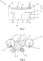
- Fig. 4 shows a movable blade 20 for a cutting device according to the invention.
- the movable blade 20 can be removed from the cutter without tools.
- the movable blade 20 has a cutting edge 21.
- the cutting edge 21 has a V-shape.
- the movable blade 20 has a recess 22. With this recess, a partial cut can be made, that is, the print medium is not completely severed in the middle and still hangs on a piece of the width of the recess. Thus, the separated part of the print medium does not fall off, but can be removed and torn off by an operator.
- the movable blade includes holes 23 which clean the fixed blade 13 as it passes.
- the movable blade 20 includes deflectors 24 on the sides of the cutting edge 21 for guiding them along the fixed blade 13.
- the direction of movement B in which the movable blade 20 moves after installation in the cutting device is indicated.
- the movable blade 20 includes two Slotted guides 26, 27, 28 over which they can be moved by drive pin of two drive gears in the direction of movement B.
- Each slotted guide has a first section 26 which extends parallel to the direction of movement B.
- the first portion 26 begins at an edge 30 which lies opposite the cutting edge 21.
- the movable blade 20 has at this edge an opening 25 into which the first portion 26 opens.
- Each slotted guide has a second section 27, which extends perpendicular to the direction of movement B of the movable blade 20 to the outside.
- the movable blade When the drive bolts are at the intersection 28 between the first gate 26 and the second section 27 of the slotted guide, the movable blade can be removed via the first section 26.
- the first portion has a first guide 31 which funnel-shaped leads into the first portion 26 and thus, together with the drive pin acts self-guiding when the movable blade 20 is introduced into the cutting device.
- the first section 26 has a second taper 32. Another recess 29 of the movable blade 20 provides space for a manual drive of the movable blade 20th
- Fig. 5 shows a gear for the cutting device.
- the transmission comprises two drive gears 40, 41, each carrying a drive pin 43, 42.
- the drive gears 40, 41 are moved via a translation of a motor with a motor gear 47 in each opposite direction.
- the drive pins 43, 42 perform a movement that is mirror-symmetrical.
- the movement of the motor gear 47 is transmitted to another gear 46, which is connected to a first ratio gear 45.
- the first ratio gear 45 drives a second ratio gear 44.
- the first and second ratio gears 45, 44 each engage a drive gear 40, 41. 41 41.
- the transmission comprises a manual gear 48, with which the further gear 46 can be moved manually, when to the Example the function of the engine has failed.
- the manual gear 48 is driven by a screwdriver.
- the screw of the manual gear is guided through the further recess 29 by the movable blade 20.
- the manual gear is no longer shown in the following drawings.
- Fig. 6 shows the gear and the moving blade 20 in a rest position. In this position, the moving blade 20 has disappeared in the housing of the cutting device.
- the drive bolts 42, 43 are in this position at the intersection 28 between the first portion 26 and the second portion 27 of the slide guides.
- Fig. 7 shows the gear and the moving blade 20 in a position when the moving blade 20 is extended or retracted along the direction of movement B.
- the drive gears 40, 41 are compared to Fig. 6 rotated by a quarter turn, so that the drive bolts 42, 43 are now on the outside of the drive gears 40, 41.
- the drive pins 42, 43 have moved along the second portion 27 of the slotted guide and the movable blade 20 is thus moved along the direction of movement B.
- Fig. 6 shows the gear and the moving blade 20 in a rest position. In this position, the moving blade 20 has disappeared in the housing of the cutting device.
- the drive bolts 42, 43 are in this position at the intersection 28 between the first portion 26 and the second portion
- FIG. 8 shows the gear and the moving blade in the cutting position or in the removal position.
- the drive gears 40, 41 are further rotated a quarter turn.
- the drive bolts 42, 43 are now at the top of the drive gears 40, 41.
- the drive bolts 42, 43 are now again at the intersection 28 between the first portion 26 and the second portion 27 of the slide guides.
- the gear wheels of the transmission are fixedly mounted in the cutting device. It can be seen that by rotation of the transmission, the drive bolts 42, 43 move along a circular path and move the moving blade 20 forward in the cutting position compared to the transmission.
- Fig. 8 shows the moving blade 20 in the cutting position.
- the cutting position is at the same time the removal position.
- the printer door 11 must be open and the moving blade 20 must remain in the removal position, while in the Operation the printer door 11 is closed and the moving blade 20 is only briefly moved to the cutting position and is immediately moved back to the rest position.
- Fig. 9 shows the side view of the moving blade 20 in the cutting device.
- the moving blade 20 is supported between a cover plate 49 of the cutter and a guide plate 50.
- the gear is mounted, the drive gears 40, 41 are mounted directly after the guide plate 50.
- the drive bolts 42, 43, pass through the guide plate 50, as will be shown below.
- the gear is held in the housing of the cutting device, as will be shown below.
- the cover plate 49 includes openings 56 for screwing to the housing.
- Fig. 10 shows the housing 12 of the cutting device.
- the housing 12 includes guide pins 51, which define the direction of movement for the moving blade 20.
- receptacles 57, 58 for the drive gears 41, 40, a receptacle 59 for a ratio gear 44, a receptacle 60 for the further gear 46 and a ratio gear 45 and a receptacle 61 for the motor gear 47.
- a receptacle 62 for shown the manual gear 48 of the transmission.
- the housing includes a receptacle 52 for the guide plate 50, which is screwed into threads 53.
- the guide plate 50 serves as a cover for the gear to hold the gears stationary.
- Fig. 11 shows the guide plate 50.
- the guide plate includes holes 54 for screwing the guide plate in the housing 12 of the cutting device.
- the guide plate 50 includes semicircular guides for the drive bolts 42, 43.
- the guide plate 50 holds the gears of the transmission in the housing 12 of the cutter and forms a guide for the moving blade 20.
Landscapes
- Life Sciences & Earth Sciences (AREA)
- Forests & Forestry (AREA)
- Engineering & Computer Science (AREA)
- Mechanical Engineering (AREA)
- Handling Of Sheets (AREA)
Priority Applications (2)
| Application Number | Priority Date | Filing Date | Title |
|---|---|---|---|
| EP17211267.4A EP3505355B1 (fr) | 2017-12-31 | 2017-12-31 | Dispositif de découpage pour rouleaux étiquettes |
| US16/211,264 US10717624B2 (en) | 2017-12-31 | 2018-12-06 | Cutting device for continuous labels |
Applications Claiming Priority (1)
| Application Number | Priority Date | Filing Date | Title |
|---|---|---|---|
| EP17211267.4A EP3505355B1 (fr) | 2017-12-31 | 2017-12-31 | Dispositif de découpage pour rouleaux étiquettes |
Publications (2)
| Publication Number | Publication Date |
|---|---|
| EP3505355A1 true EP3505355A1 (fr) | 2019-07-03 |
| EP3505355B1 EP3505355B1 (fr) | 2022-01-26 |
Family
ID=60888301
Family Applications (1)
| Application Number | Title | Priority Date | Filing Date |
|---|---|---|---|
| EP17211267.4A Active EP3505355B1 (fr) | 2017-12-31 | 2017-12-31 | Dispositif de découpage pour rouleaux étiquettes |
Country Status (2)
| Country | Link |
|---|---|
| US (1) | US10717624B2 (fr) |
| EP (1) | EP3505355B1 (fr) |
Cited By (3)
| Publication number | Priority date | Publication date | Assignee | Title |
|---|---|---|---|---|
| EP3936446A1 (fr) * | 2020-07-10 | 2022-01-12 | Bizerba SE & Co. KG | Procédé de séparation d'étiquettes |
| EP3967503A1 (fr) * | 2020-09-11 | 2022-03-16 | Bizerba SE & Co. KG | Imprimante d'étiquettes |
| US12129142B2 (en) | 2020-07-10 | 2024-10-29 | Bizerba SE & Co. KG | Cutter for self-adhesive linerless endless tape labels |
Citations (3)
| Publication number | Priority date | Publication date | Assignee | Title |
|---|---|---|---|---|
| US6109154A (en) * | 1997-03-18 | 2000-08-29 | Fujitsu Takamisawa Component Limited | Sheet-cutter having motor driven push cutter |
| US20100086340A1 (en) * | 2008-10-08 | 2010-04-08 | Brother Kogyo Kabushiki Kaisha | Cutting mechanism for printing apparatus, and printing apparatus including the same |
| EP2842757B1 (fr) | 2013-08-28 | 2017-04-19 | Fujitsu Component Limited | Imprimante |
Family Cites Families (6)
| Publication number | Priority date | Publication date | Assignee | Title |
|---|---|---|---|---|
| US4312597A (en) * | 1977-11-06 | 1982-01-26 | Copal Company Limited | Printer |
| JP3800891B2 (ja) * | 1999-10-29 | 2006-07-26 | スター精密株式会社 | プリンタ |
| JP3730153B2 (ja) * | 2001-10-18 | 2005-12-21 | セイコーインスツル株式会社 | プリンタのカッター装置 |
| JP4455091B2 (ja) * | 2004-02-20 | 2010-04-21 | スター精密株式会社 | 用紙カッター |
| JP4715457B2 (ja) * | 2005-11-16 | 2011-07-06 | セイコーエプソン株式会社 | シート切断装置、およびこれを備えた印刷装置 |
| KR101282299B1 (ko) * | 2012-12-21 | 2013-07-10 | 이일복 | 프린터의 커터 |
-
2017
- 2017-12-31 EP EP17211267.4A patent/EP3505355B1/fr active Active
-
2018
- 2018-12-06 US US16/211,264 patent/US10717624B2/en active Active
Patent Citations (3)
| Publication number | Priority date | Publication date | Assignee | Title |
|---|---|---|---|---|
| US6109154A (en) * | 1997-03-18 | 2000-08-29 | Fujitsu Takamisawa Component Limited | Sheet-cutter having motor driven push cutter |
| US20100086340A1 (en) * | 2008-10-08 | 2010-04-08 | Brother Kogyo Kabushiki Kaisha | Cutting mechanism for printing apparatus, and printing apparatus including the same |
| EP2842757B1 (fr) | 2013-08-28 | 2017-04-19 | Fujitsu Component Limited | Imprimante |
Cited By (6)
| Publication number | Priority date | Publication date | Assignee | Title |
|---|---|---|---|---|
| EP3936446A1 (fr) * | 2020-07-10 | 2022-01-12 | Bizerba SE & Co. KG | Procédé de séparation d'étiquettes |
| US11685134B2 (en) | 2020-07-10 | 2023-06-27 | Bizerba SE & Co. KG | Method of cutting off labels |
| US12129142B2 (en) | 2020-07-10 | 2024-10-29 | Bizerba SE & Co. KG | Cutter for self-adhesive linerless endless tape labels |
| EP3967503A1 (fr) * | 2020-09-11 | 2022-03-16 | Bizerba SE & Co. KG | Imprimante d'étiquettes |
| EP4105030A1 (fr) * | 2020-09-11 | 2022-12-21 | Bizerba SE & Co. KG | Imprimante d'étiquettes |
| US11794497B2 (en) | 2020-09-11 | 2023-10-24 | Bizerba SE & Co. KG | Label printer |
Also Published As
| Publication number | Publication date |
|---|---|
| EP3505355B1 (fr) | 2022-01-26 |
| US20190202654A1 (en) | 2019-07-04 |
| US10717624B2 (en) | 2020-07-21 |
Similar Documents
| Publication | Publication Date | Title |
|---|---|---|
| DE68920497T3 (de) | Apparat zum stufenweisen Abisolieren von Draht. | |
| AT514929B1 (de) | Werkzeugrüstsystem für Biegepresse | |
| DE2701068A1 (de) | Schlitzvorrichtung fuer bahnenfoermiges material | |
| DE1927769B2 (de) | Vorrichtung zum Herstellen von Streifen durch in Längsrichtung erfolgendes Schlitzen einer Papierbahn | |
| DE112017004840T5 (de) | Rotative Abisoliervorrichtung | |
| DE602005000347T2 (de) | Kraftübertragungsvorrichtung und diese enthaltendes Zufuhrgerät für plattenförmiges Material | |
| DE102007012777A1 (de) | Verfahren und Vorrichtung zum gesteuerten Verschließen wenigstens eines Clips um einen füllgutfreien Zopfabschnitt zwischen zwei mit einer Hülle umschlossenen Füllgutabschnitten | |
| EP3505355A1 (fr) | Dispositif de découpage pour rouleaux étiquettes | |
| EP1330324A1 (fr) | Element de cisaillage a lame circulaire compact | |
| EP3566985B1 (fr) | Dispositif d'empilement de plateaux pourvu d'un moyen de décharge | |
| EP1415944B1 (fr) | Appareil pour l'ajustement de rouleaux de pression et/ou de lames de coupe dans une plieuse | |
| EP2964550B1 (fr) | Dispositif de positionnement et/ou d'orientation d'un ou plusieurs composants déflecteurs réglables servant à diriger et/ou guider des articles dans un système de transport | |
| EP0640547A1 (fr) | Casier rotatif pour piles sur un dispositif à mouvement croisé pour produits imprimés | |
| DE19953908A1 (de) | Hochgeschwindigkeitsschere zum Querteilen von Walzband | |
| DE102010007917B4 (de) | Handbetätigtes Werkzeug | |
| EP3560668A1 (fr) | Dispositif et procédé de coupe de produits, en particulier d'une masse de confiserie | |
| DE1710632C3 (de) | Vorrichtung zum Fibrillieren von unter Spannung stehenden Folienbandern oder Faden | |
| DE1013664B (de) | Vorrichtung zum Einstellen der Anlegemarken in einer Bogen bearbeitenden Maschine, wie Druckmaschine und Presse zum Schneiden von Papier oder Pappe | |
| EP1799457B1 (fr) | Dispositif comportant plusieurs rouleaux | |
| DE102020107945B4 (de) | Umreifungsvorrichtung mit Einrichtung zum Drehen eines Packstückes | |
| DE10162446A1 (de) | Schneidwerk mit einem spiralförmigen Mechanismus zum Verändern der Schnittlänge und Verfahren zum Betreiben des Schneidwerks | |
| EP4438254A2 (fr) | Dispositif pour la découpe d'emballages | |
| DE4411905C2 (de) | Verfahren und Vorrichtung zur Probenahme von einem Materialband-Bund | |
| EP1184314A2 (fr) | Dispositif pour le guidage des feuilles, en particulier dans la zone de sortie d'un cylindre de découpage dans un appareil de pliage d'une machine d'impression rotative | |
| DE4202186A1 (de) | Schneidapparat |
Legal Events
| Date | Code | Title | Description |
|---|---|---|---|
| PUAI | Public reference made under article 153(3) epc to a published international application that has entered the european phase |
Free format text: ORIGINAL CODE: 0009012 |
|
| STAA | Information on the status of an ep patent application or granted ep patent |
Free format text: STATUS: THE APPLICATION HAS BEEN PUBLISHED |
|
| AK | Designated contracting states |
Kind code of ref document: A1 Designated state(s): AL AT BE BG CH CY CZ DE DK EE ES FI FR GB GR HR HU IE IS IT LI LT LU LV MC MK MT NL NO PL PT RO RS SE SI SK SM TR |
|
| AX | Request for extension of the european patent |
Extension state: BA ME |
|
| STAA | Information on the status of an ep patent application or granted ep patent |
Free format text: STATUS: REQUEST FOR EXAMINATION WAS MADE |
|
| 17P | Request for examination filed |
Effective date: 20191219 |
|
| RBV | Designated contracting states (corrected) |
Designated state(s): AL AT BE BG CH CY CZ DE DK EE ES FI FR GB GR HR HU IE IS IT LI LT LU LV MC MK MT NL NO PL PT RO RS SE SI SK SM TR |
|
| GRAP | Despatch of communication of intention to grant a patent |
Free format text: ORIGINAL CODE: EPIDOSNIGR1 |
|
| STAA | Information on the status of an ep patent application or granted ep patent |
Free format text: STATUS: GRANT OF PATENT IS INTENDED |
|
| INTG | Intention to grant announced |
Effective date: 20211021 |
|
| GRAS | Grant fee paid |
Free format text: ORIGINAL CODE: EPIDOSNIGR3 |
|
| GRAA | (expected) grant |
Free format text: ORIGINAL CODE: 0009210 |
|
| STAA | Information on the status of an ep patent application or granted ep patent |
Free format text: STATUS: THE PATENT HAS BEEN GRANTED |
|
| AK | Designated contracting states |
Kind code of ref document: B1 Designated state(s): AL AT BE BG CH CY CZ DE DK EE ES FI FR GB GR HR HU IE IS IT LI LT LU LV MC MK MT NL NO PL PT RO RS SE SI SK SM TR |
|
| REG | Reference to a national code |
Ref country code: GB Ref legal event code: FG4D Free format text: NOT ENGLISH |
|
| REG | Reference to a national code |
Ref country code: CH Ref legal event code: EP |
|
| REG | Reference to a national code |
Ref country code: AT Ref legal event code: REF Ref document number: 1464975 Country of ref document: AT Kind code of ref document: T Effective date: 20220215 |
|
| REG | Reference to a national code |
Ref country code: IE Ref legal event code: FG4D Free format text: LANGUAGE OF EP DOCUMENT: GERMAN |
|
| REG | Reference to a national code |
Ref country code: DE Ref legal event code: R096 Ref document number: 502017012512 Country of ref document: DE |
|
| REG | Reference to a national code |
Ref country code: LT Ref legal event code: MG9D |
|
| REG | Reference to a national code |
Ref country code: NL Ref legal event code: MP Effective date: 20220126 |
|
| PG25 | Lapsed in a contracting state [announced via postgrant information from national office to epo] |
Ref country code: NL Free format text: LAPSE BECAUSE OF FAILURE TO SUBMIT A TRANSLATION OF THE DESCRIPTION OR TO PAY THE FEE WITHIN THE PRESCRIBED TIME-LIMIT Effective date: 20220126 |
|
| PG25 | Lapsed in a contracting state [announced via postgrant information from national office to epo] |
Ref country code: SE Free format text: LAPSE BECAUSE OF FAILURE TO SUBMIT A TRANSLATION OF THE DESCRIPTION OR TO PAY THE FEE WITHIN THE PRESCRIBED TIME-LIMIT Effective date: 20220126 Ref country code: RS Free format text: LAPSE BECAUSE OF FAILURE TO SUBMIT A TRANSLATION OF THE DESCRIPTION OR TO PAY THE FEE WITHIN THE PRESCRIBED TIME-LIMIT Effective date: 20220126 Ref country code: PT Free format text: LAPSE BECAUSE OF FAILURE TO SUBMIT A TRANSLATION OF THE DESCRIPTION OR TO PAY THE FEE WITHIN THE PRESCRIBED TIME-LIMIT Effective date: 20220526 Ref country code: NO Free format text: LAPSE BECAUSE OF FAILURE TO SUBMIT A TRANSLATION OF THE DESCRIPTION OR TO PAY THE FEE WITHIN THE PRESCRIBED TIME-LIMIT Effective date: 20220426 Ref country code: LT Free format text: LAPSE BECAUSE OF FAILURE TO SUBMIT A TRANSLATION OF THE DESCRIPTION OR TO PAY THE FEE WITHIN THE PRESCRIBED TIME-LIMIT Effective date: 20220126 Ref country code: HR Free format text: LAPSE BECAUSE OF FAILURE TO SUBMIT A TRANSLATION OF THE DESCRIPTION OR TO PAY THE FEE WITHIN THE PRESCRIBED TIME-LIMIT Effective date: 20220126 Ref country code: ES Free format text: LAPSE BECAUSE OF FAILURE TO SUBMIT A TRANSLATION OF THE DESCRIPTION OR TO PAY THE FEE WITHIN THE PRESCRIBED TIME-LIMIT Effective date: 20220126 Ref country code: BG Free format text: LAPSE BECAUSE OF FAILURE TO SUBMIT A TRANSLATION OF THE DESCRIPTION OR TO PAY THE FEE WITHIN THE PRESCRIBED TIME-LIMIT Effective date: 20220426 |
|
| PG25 | Lapsed in a contracting state [announced via postgrant information from national office to epo] |
Ref country code: PL Free format text: LAPSE BECAUSE OF FAILURE TO SUBMIT A TRANSLATION OF THE DESCRIPTION OR TO PAY THE FEE WITHIN THE PRESCRIBED TIME-LIMIT Effective date: 20220126 Ref country code: LV Free format text: LAPSE BECAUSE OF FAILURE TO SUBMIT A TRANSLATION OF THE DESCRIPTION OR TO PAY THE FEE WITHIN THE PRESCRIBED TIME-LIMIT Effective date: 20220126 Ref country code: GR Free format text: LAPSE BECAUSE OF FAILURE TO SUBMIT A TRANSLATION OF THE DESCRIPTION OR TO PAY THE FEE WITHIN THE PRESCRIBED TIME-LIMIT Effective date: 20220427 Ref country code: FI Free format text: LAPSE BECAUSE OF FAILURE TO SUBMIT A TRANSLATION OF THE DESCRIPTION OR TO PAY THE FEE WITHIN THE PRESCRIBED TIME-LIMIT Effective date: 20220126 |
|
| PG25 | Lapsed in a contracting state [announced via postgrant information from national office to epo] |
Ref country code: IS Free format text: LAPSE BECAUSE OF FAILURE TO SUBMIT A TRANSLATION OF THE DESCRIPTION OR TO PAY THE FEE WITHIN THE PRESCRIBED TIME-LIMIT Effective date: 20220526 |
|
| REG | Reference to a national code |
Ref country code: DE Ref legal event code: R097 Ref document number: 502017012512 Country of ref document: DE |
|
| PG25 | Lapsed in a contracting state [announced via postgrant information from national office to epo] |
Ref country code: SM Free format text: LAPSE BECAUSE OF FAILURE TO SUBMIT A TRANSLATION OF THE DESCRIPTION OR TO PAY THE FEE WITHIN THE PRESCRIBED TIME-LIMIT Effective date: 20220126 Ref country code: SK Free format text: LAPSE BECAUSE OF FAILURE TO SUBMIT A TRANSLATION OF THE DESCRIPTION OR TO PAY THE FEE WITHIN THE PRESCRIBED TIME-LIMIT Effective date: 20220126 Ref country code: RO Free format text: LAPSE BECAUSE OF FAILURE TO SUBMIT A TRANSLATION OF THE DESCRIPTION OR TO PAY THE FEE WITHIN THE PRESCRIBED TIME-LIMIT Effective date: 20220126 Ref country code: EE Free format text: LAPSE BECAUSE OF FAILURE TO SUBMIT A TRANSLATION OF THE DESCRIPTION OR TO PAY THE FEE WITHIN THE PRESCRIBED TIME-LIMIT Effective date: 20220126 Ref country code: DK Free format text: LAPSE BECAUSE OF FAILURE TO SUBMIT A TRANSLATION OF THE DESCRIPTION OR TO PAY THE FEE WITHIN THE PRESCRIBED TIME-LIMIT Effective date: 20220126 Ref country code: CZ Free format text: LAPSE BECAUSE OF FAILURE TO SUBMIT A TRANSLATION OF THE DESCRIPTION OR TO PAY THE FEE WITHIN THE PRESCRIBED TIME-LIMIT Effective date: 20220126 |
|
| PG25 | Lapsed in a contracting state [announced via postgrant information from national office to epo] |
Ref country code: AL Free format text: LAPSE BECAUSE OF FAILURE TO SUBMIT A TRANSLATION OF THE DESCRIPTION OR TO PAY THE FEE WITHIN THE PRESCRIBED TIME-LIMIT Effective date: 20220126 |
|
| PLBE | No opposition filed within time limit |
Free format text: ORIGINAL CODE: 0009261 |
|
| STAA | Information on the status of an ep patent application or granted ep patent |
Free format text: STATUS: NO OPPOSITION FILED WITHIN TIME LIMIT |
|
| 26N | No opposition filed |
Effective date: 20221027 |
|
| PG25 | Lapsed in a contracting state [announced via postgrant information from national office to epo] |
Ref country code: SI Free format text: LAPSE BECAUSE OF FAILURE TO SUBMIT A TRANSLATION OF THE DESCRIPTION OR TO PAY THE FEE WITHIN THE PRESCRIBED TIME-LIMIT Effective date: 20220126 |
|
| PG25 | Lapsed in a contracting state [announced via postgrant information from national office to epo] |
Ref country code: IT Free format text: LAPSE BECAUSE OF FAILURE TO SUBMIT A TRANSLATION OF THE DESCRIPTION OR TO PAY THE FEE WITHIN THE PRESCRIBED TIME-LIMIT Effective date: 20220126 |
|
| REG | Reference to a national code |
Ref country code: CH Ref legal event code: PL |
|
| REG | Reference to a national code |
Ref country code: BE Ref legal event code: MM Effective date: 20221231 |
|
| PG25 | Lapsed in a contracting state [announced via postgrant information from national office to epo] |
Ref country code: LU Free format text: LAPSE BECAUSE OF NON-PAYMENT OF DUE FEES Effective date: 20221231 |
|
| PG25 | Lapsed in a contracting state [announced via postgrant information from national office to epo] |
Ref country code: LI Free format text: LAPSE BECAUSE OF NON-PAYMENT OF DUE FEES Effective date: 20221231 Ref country code: IE Free format text: LAPSE BECAUSE OF NON-PAYMENT OF DUE FEES Effective date: 20221231 Ref country code: CH Free format text: LAPSE BECAUSE OF NON-PAYMENT OF DUE FEES Effective date: 20221231 |
|
| PG25 | Lapsed in a contracting state [announced via postgrant information from national office to epo] |
Ref country code: BE Free format text: LAPSE BECAUSE OF NON-PAYMENT OF DUE FEES Effective date: 20221231 |
|
| REG | Reference to a national code |
Ref country code: AT Ref legal event code: MM01 Ref document number: 1464975 Country of ref document: AT Kind code of ref document: T Effective date: 20221231 |
|
| PG25 | Lapsed in a contracting state [announced via postgrant information from national office to epo] |
Ref country code: HU Free format text: LAPSE BECAUSE OF FAILURE TO SUBMIT A TRANSLATION OF THE DESCRIPTION OR TO PAY THE FEE WITHIN THE PRESCRIBED TIME-LIMIT; INVALID AB INITIO Effective date: 20171231 |
|
| PG25 | Lapsed in a contracting state [announced via postgrant information from national office to epo] |
Ref country code: AT Free format text: LAPSE BECAUSE OF NON-PAYMENT OF DUE FEES Effective date: 20221231 |
|
| PG25 | Lapsed in a contracting state [announced via postgrant information from national office to epo] |
Ref country code: CY Free format text: LAPSE BECAUSE OF FAILURE TO SUBMIT A TRANSLATION OF THE DESCRIPTION OR TO PAY THE FEE WITHIN THE PRESCRIBED TIME-LIMIT Effective date: 20220126 Ref country code: AT Free format text: LAPSE BECAUSE OF NON-PAYMENT OF DUE FEES Effective date: 20221231 |
|
| PG25 | Lapsed in a contracting state [announced via postgrant information from national office to epo] |
Ref country code: MK Free format text: LAPSE BECAUSE OF FAILURE TO SUBMIT A TRANSLATION OF THE DESCRIPTION OR TO PAY THE FEE WITHIN THE PRESCRIBED TIME-LIMIT Effective date: 20220126 |
|
| PG25 | Lapsed in a contracting state [announced via postgrant information from national office to epo] |
Ref country code: MC Free format text: LAPSE BECAUSE OF FAILURE TO SUBMIT A TRANSLATION OF THE DESCRIPTION OR TO PAY THE FEE WITHIN THE PRESCRIBED TIME-LIMIT Effective date: 20220126 |
|
| PG25 | Lapsed in a contracting state [announced via postgrant information from national office to epo] |
Ref country code: TR Free format text: LAPSE BECAUSE OF FAILURE TO SUBMIT A TRANSLATION OF THE DESCRIPTION OR TO PAY THE FEE WITHIN THE PRESCRIBED TIME-LIMIT Effective date: 20220126 Ref country code: MC Free format text: LAPSE BECAUSE OF FAILURE TO SUBMIT A TRANSLATION OF THE DESCRIPTION OR TO PAY THE FEE WITHIN THE PRESCRIBED TIME-LIMIT Effective date: 20220126 |
|
| PG25 | Lapsed in a contracting state [announced via postgrant information from national office to epo] |
Ref country code: MT Free format text: LAPSE BECAUSE OF FAILURE TO SUBMIT A TRANSLATION OF THE DESCRIPTION OR TO PAY THE FEE WITHIN THE PRESCRIBED TIME-LIMIT Effective date: 20220126 |
|
| PGFP | Annual fee paid to national office [announced via postgrant information from national office to epo] |
Ref country code: GB Payment date: 20251218 Year of fee payment: 9 |
|
| PGFP | Annual fee paid to national office [announced via postgrant information from national office to epo] |
Ref country code: FR Payment date: 20251218 Year of fee payment: 9 |
|
| PGFP | Annual fee paid to national office [announced via postgrant information from national office to epo] |
Ref country code: DE Payment date: 20251222 Year of fee payment: 9 |