EP3560668A1 - Vorrichtung und verfahren zum schneiden eines produkts, insbesondere aus süsswarenmasse - Google Patents
Vorrichtung und verfahren zum schneiden eines produkts, insbesondere aus süsswarenmasse Download PDFInfo
- Publication number
- EP3560668A1 EP3560668A1 EP19159884.6A EP19159884A EP3560668A1 EP 3560668 A1 EP3560668 A1 EP 3560668A1 EP 19159884 A EP19159884 A EP 19159884A EP 3560668 A1 EP3560668 A1 EP 3560668A1
- Authority
- EP
- European Patent Office
- Prior art keywords
- cutting
- cutting means
- shaft
- holder
- gripper
- Prior art date
- Legal status (The legal status is an assumption and is not a legal conclusion. Google has not performed a legal analysis and makes no representation as to the accuracy of the status listed.)
- Granted
Links
Images



Classifications
-
- B—PERFORMING OPERATIONS; TRANSPORTING
- B26—HAND CUTTING TOOLS; CUTTING; SEVERING
- B26D—CUTTING; DETAILS COMMON TO MACHINES FOR PERFORATING, PUNCHING, CUTTING-OUT, STAMPING-OUT OR SEVERING
- B26D7/00—Details of apparatus for cutting, cutting-out, stamping-out, punching, perforating, or severing by means other than cutting
- B26D7/26—Means for mounting or adjusting the cutting member; Means for adjusting the stroke of the cutting member
-
- A—HUMAN NECESSITIES
- A23—FOODS OR FOODSTUFFS; TREATMENT THEREOF, NOT COVERED BY OTHER CLASSES
- A23G—COCOA; COCOA PRODUCTS, e.g. CHOCOLATE; SUBSTITUTES FOR COCOA OR COCOA PRODUCTS; CONFECTIONERY; CHEWING GUM; ICE-CREAM; PREPARATION THEREOF
- A23G7/00—Other apparatus or process specially adapted for the chocolate or confectionery industry
- A23G7/0018—Apparatus for cutting or dividing chocolate or candies
-
- B—PERFORMING OPERATIONS; TRANSPORTING
- B26—HAND CUTTING TOOLS; CUTTING; SEVERING
- B26D—CUTTING; DETAILS COMMON TO MACHINES FOR PERFORATING, PUNCHING, CUTTING-OUT, STAMPING-OUT OR SEVERING
- B26D1/00—Cutting through work characterised by the nature or movement of the cutting member or particular materials not otherwise provided for; Apparatus or machines therefor; Cutting members therefor
- B26D1/01—Cutting through work characterised by the nature or movement of the cutting member or particular materials not otherwise provided for; Apparatus or machines therefor; Cutting members therefor involving a cutting member which does not travel with the work
- B26D1/12—Cutting through work characterised by the nature or movement of the cutting member or particular materials not otherwise provided for; Apparatus or machines therefor; Cutting members therefor involving a cutting member which does not travel with the work having a cutting member moving about an axis
- B26D1/14—Cutting through work characterised by the nature or movement of the cutting member or particular materials not otherwise provided for; Apparatus or machines therefor; Cutting members therefor involving a cutting member which does not travel with the work having a cutting member moving about an axis with a circular cutting member, e.g. disc cutter
- B26D1/22—Cutting through work characterised by the nature or movement of the cutting member or particular materials not otherwise provided for; Apparatus or machines therefor; Cutting members therefor involving a cutting member which does not travel with the work having a cutting member moving about an axis with a circular cutting member, e.g. disc cutter coacting with a movable member, e.g. a roller
-
- B—PERFORMING OPERATIONS; TRANSPORTING
- B26—HAND CUTTING TOOLS; CUTTING; SEVERING
- B26D—CUTTING; DETAILS COMMON TO MACHINES FOR PERFORATING, PUNCHING, CUTTING-OUT, STAMPING-OUT OR SEVERING
- B26D1/00—Cutting through work characterised by the nature or movement of the cutting member or particular materials not otherwise provided for; Apparatus or machines therefor; Cutting members therefor
- B26D1/01—Cutting through work characterised by the nature or movement of the cutting member or particular materials not otherwise provided for; Apparatus or machines therefor; Cutting members therefor involving a cutting member which does not travel with the work
- B26D1/12—Cutting through work characterised by the nature or movement of the cutting member or particular materials not otherwise provided for; Apparatus or machines therefor; Cutting members therefor involving a cutting member which does not travel with the work having a cutting member moving about an axis
- B26D1/14—Cutting through work characterised by the nature or movement of the cutting member or particular materials not otherwise provided for; Apparatus or machines therefor; Cutting members therefor involving a cutting member which does not travel with the work having a cutting member moving about an axis with a circular cutting member, e.g. disc cutter
- B26D1/24—Cutting through work characterised by the nature or movement of the cutting member or particular materials not otherwise provided for; Apparatus or machines therefor; Cutting members therefor involving a cutting member which does not travel with the work having a cutting member moving about an axis with a circular cutting member, e.g. disc cutter coacting with another disc cutter
-
- B—PERFORMING OPERATIONS; TRANSPORTING
- B26—HAND CUTTING TOOLS; CUTTING; SEVERING
- B26D—CUTTING; DETAILS COMMON TO MACHINES FOR PERFORATING, PUNCHING, CUTTING-OUT, STAMPING-OUT OR SEVERING
- B26D7/00—Details of apparatus for cutting, cutting-out, stamping-out, punching, perforating, or severing by means other than cutting
- B26D7/26—Means for mounting or adjusting the cutting member; Means for adjusting the stroke of the cutting member
- B26D2007/2657—Auxiliary carriages for moving the tool holders
-
- B—PERFORMING OPERATIONS; TRANSPORTING
- B26—HAND CUTTING TOOLS; CUTTING; SEVERING
- B26D—CUTTING; DETAILS COMMON TO MACHINES FOR PERFORATING, PUNCHING, CUTTING-OUT, STAMPING-OUT OR SEVERING
- B26D7/00—Details of apparatus for cutting, cutting-out, stamping-out, punching, perforating, or severing by means other than cutting
- B26D7/26—Means for mounting or adjusting the cutting member; Means for adjusting the stroke of the cutting member
- B26D7/2614—Means for mounting the cutting member
- B26D7/2621—Means for mounting the cutting member for circular cutters
-
- B—PERFORMING OPERATIONS; TRANSPORTING
- B26—HAND CUTTING TOOLS; CUTTING; SEVERING
- B26D—CUTTING; DETAILS COMMON TO MACHINES FOR PERFORATING, PUNCHING, CUTTING-OUT, STAMPING-OUT OR SEVERING
- B26D7/00—Details of apparatus for cutting, cutting-out, stamping-out, punching, perforating, or severing by means other than cutting
- B26D7/26—Means for mounting or adjusting the cutting member; Means for adjusting the stroke of the cutting member
- B26D7/2628—Means for adjusting the position of the cutting member
- B26D7/2635—Means for adjusting the position of the cutting member for circular cutters
Definitions
- the present invention relates to an apparatus and a method for cutting a product, in particular confectionery mass, according to the preamble of the independent claims.
- a generic device for separating individual pieces of a continuously moving mass strand is from the EP 1094717 B1 known.
- the cutting blades each run on a circular path.
- the two cutting blades are each arranged on a disk-shaped element on an axis parallel to the axis of rotation of the element and the cutting blade knife holders are coupled to align the cutting blades perpendicular to the conveying direction of the mass strand by means of at least one rod which extends laterally of the cutting blade and aligned with this wherein the knife holders are slidably disposed on the at least one rod.
- a cutting device which uses two format knife shafts in the machine and, depending on the format, one or the other format knife shaft is used.
- the number of formats is limited.
- the device according to the invention and the method according to the invention for cutting a product, in particular of confectionery mass, with the features of the independent claims have the advantage that the flexibility and safety of the arrangement is further increased.
- the user can individually change the position and the distance to the adjacent cutting means as needed for each cutting means.
- an adjusting device according to the invention is provided for displacing the cutting means along the cutting shaft. Replacing a complete knife shaft is no longer necessary.
- An automatic adjustment of the product width is possible without having to install or remove additional parts. This also allows for optimization of the cutting width of the product and can reduce waste. By eliminating the assembly of the format-knife shaft with a change of the product width mounting errors, adjustment errors or damage to the cutting means by the operator are excluded.
- At least one fixing device is provided for releasably fixing the cutting means to the cutting shaft. This allows the cutting means on the one hand safely connect to the cutting shaft to cut the product reliable. On the other hand, through the releasable design of the fixing the cutting means along the cutting axis are moved to change the position, so that a quick and flexible adaptation to desired cutting widths is particularly simple without having to make an exchange of the entire cutting device.
- the adjusting device acts to release or fix the cutting means on the cutting shaft to the fixing device.
- the existing anyway for moving the cutting means adjusting can be used as an actuator for the fixing without much additional effort. This allows the device to remain simple.
- the adjusting device is designed to move at least one gripper to the cutting means, to grip the cutting means and / or a support connected to the cutting means, and to move the gripper with the cutting means along the cutting shaft.
- the adjusting device and / or the cutting shaft for releasing or fixing the cutting means with respect to the cutting shaft is designed to the effect that a relative movement between the cutting means and the cutting shaft is generated.
- the fixation and release can be made by already existing drive means.
- an increased complexity of the device can be avoided.
- a device 8 for cutting a product, in particular of candy mass comprises at least one transport device 10.
- the transport device 10 is designed, for example, as a conveyor belt.
- the transport device 10 feeds a product carpet to be cut in the transport direction 11 of a cutting device 25.
- the cut product is removed by a further transport device 14 from the cutting device 25 for further processing.
- the cutting device 25 comprises a plurality of cutting means 26, in particular a cutting blade, which are arranged on a cutting shaft 28.
- the cutting means 26 are for example annular.
- the cutting edge has a generally tapered portion to suitably to cut the product into strips 11 in transport direction 11.
- the cutting means 26 can rotate together with the cutting shaft 28.
- the cutting means 26 is each fixed by a holder 24 slidably with the cutting shaft 28. If the holder 24 is released, the cutting means 26 can be displaced along the cutting shaft 28. If the holder 24 is fixed, then the cutting means 26 moves together with the rotating cutting shaft 28.
- the holder 24 is, for example, annular or sleeve-shaped and establishes the connection between the cutting shaft 28 and the cutting means 26.
- the cutting means 26 is fixed to the Holder 24 connected.
- the width of the preferably annular holder 24 is usually chosen slightly wider than the width of the cutting means 26 in order to ensure a secure releasable connection with the cutting shaft 28.
- the holder 24 serves as a gripping surface for a gripper 20 for moving the holder 24 with cutting means 26.
- the cutting shaft 28 is arranged transversely to the transport direction 11.
- the cutting means 26 with the associated cutting edge are aligned parallel to the transport direction 11.
- the distance between two adjacent cutting means 26 defines the width of the product strand or the product strand width.
- a counter-holder 12 is arranged. Between the counter-holder 12 and the cutting edges of the cutting means 26 comes to be cut product or product carpet to lie.
- the counter-holder 12 may for example be designed as a counter-cutting roller or as a plate over which the product is guided.
- the counter-holder 12 extends transversely to the transport direction 11 over the entire width of the transport device 10 or 14.
- a carriage 18 can be moved.
- the carriage 18 can preferably be moved parallel to the axis of the cutting shaft 28 and thus transversely to the transport direction 11.
- the guide 16 is formed, for example, as a guide rod or two or more, parallel to each other and also parallel to the cutting shaft 28 positioned guide rods. In the exemplary embodiment, the guide 16 is located above the cutting shaft 28. However, this could also be arranged laterally or according to space at another suitable location.
- At least one gripper 20 with a movable gripper arm 22 is arranged on the carriage 18.
- the gripper 20 with it fixed Greifam 22 can be moved by the carriage 18 in a suitable position to move the individual cutting means 26 with associated holder 24 relative to the cutting shaft 28.
- the described components guide 16, slide 18, gripper 20, gripper arm 22 form an adjusting device 15 for adjusting the cutting means 26 relative to the cutting shaft 28, in particular in the axial direction of the cutting shaft 28.
- the adjusting device 15 may also be adapted to the holder 24 and / or to move the cutting means 26 relative to the cutting shaft 28 in, for example, a movement about the axis of the cutting shaft 28, for example rotating.
- the adjusting device 15 may serve to actuate a mechanism on the holder 24 and / or cutting means 26, for example, to allow a clamping or releasing of the holder 24 relative to the cutting shaft 28.
- the cutting means 26 there are two different areas 30, 32 in which the cutting means 26 are located in the device 8. If the cutting means 26 is substantially in the area of the transport device 10 or the cutting means 26 can act on the product moved by the transport device 10, then the cutting means 26 is located in a production area 30. If the cutting means 26 can not act on the product
- the parking area 32 is characterized in that the cutting shaft 28 is not arranged above the transport device 10 in this area, but laterally. In the parking area 32 those cutting means 26 are positioned that are not needed for the current production process, which should therefore not be in the production area 30.
- FIGS. 4 and 5 is a first variant for releasably clamping the individual cutting means 26 by means of a fixing device 33 shown in more detail.
- the cutting means 26 is attached via a ring 38 with the holder 24, for example by screw connections such as the cut in FIG. 4 refer to.
- the spline 34 is fixedly connected to the cutting shaft 28.
- the spline shaft 34 may be part of the cutting shaft 28.
- the splined shaft 34 has a substantially cylindrical shape, wherein the outer diameter of the splined shaft 34 does not run constant over all regions, but increases in a wedge shape along the circumference. Following the wedge-shaped region 37 takes the outer contour again radially. Following this, it again increases radially in the form of a further wedge-shaped region 37. By way of example, three wedge-shaped regions 37 are provided. The outer contour of the spline 34 cooperates with the holder 24.
- the inner contour of the holder 24 has wedge-shaped regions 37 which cooperate frictionally with the wedge-shaped regions 37 of the spline 34.
- the number of wedge-shaped portions 37 of the holder 24 corresponds to that of the spline 34.
- the geometry of the wedge-shaped portions 37 of the holder 24 is similar to that of the spline 34.
- a release of the cutting means 26 is carried by the cutting shaft 28 to allow a displacement of the cutting means 26 in the axial direction of the cutting shaft 28.
- the generation of the relative movement can take place as already described above.
- the gripper 20 engages the protruding part of the holder 24 and fixes it.
- the spline shaft 34 or cutting shaft 28 performs a corresponding short rotational movement to release the clamping action of the wedge-shaped regions 37. Clamping is effected by a corresponding opposite movement of the spline shaft 34 or cutting shaft 28 relative to the holder 24.
- the fixing device 33 In the embodiment according to the FIGS. 4 and 5 form the spline 34 and the wedge-shaped portions 37 on both the spline 34 and the holder 24, the fixing device 33.
- the actuation of the fixing device 33 is effected as described by applying a relative movement between the splined shaft 34 and the cutting shaft 28 and the wedge-shaped regions 37 the holder 24.
- FIGS. 6 to 8 may be a clamping of the cutting means 26 relative to the cutting shaft 28 using the fixing device 33 by the provision of a clamping arm 40 in Cooperation with the holder 24 done.
- a clamping arm 40 On the clamping arm 40 as well as on the holder 24 each radially outwardly projecting webs 42 are arranged.
- An actuation of the clamping arm 40 takes place in that the gripping arm 22 of the gripper 20 comes into contact both with the upper side of the holder 24 and with the clamping arm 40, as well as compressing the two webs 42 at the same time FIGS.
- the clamping mechanism is released, for example, by a clamping of the holder 24 relative to the cutting shaft 28 caused by the clamping arm 40 or some other clamping mechanism being released.
- a key for torque transmission can be used.
- the fixing device 33 is formed by the clamping arm 40 and the other arm on the holder 24, and optionally by clamping means such as the key, not shown, or the like.
- the gripper 20 holds the clamping arm 40 or the arm on the holder 24 in order to activate the fixing device 33.
- Clamping the fixing device 33 causes a fixed connection between the cutting means 26 and the cutting shaft 28.
- a release of the fixing device 33 causes a displacement of the cutting means 26 along the cutting shaft 28th
- the described device 8 operates as follows. Before a new product strand width is set, it is checked by a program stored in a control whether an adjustment of all cutting means 26 or only individual cutting means 26 is necessary. If an adjustment of all cutting means 26 is necessary, then first those cutting means 26 are driven into the parking area 32, which are not required. Subsequently, the cutting means 26 to be used are individually moved to the respective position. The positions can be chosen freely and thus be different.
- the cutting means 26 can automatically, individually and continuously adjusted to the desired product width and individually fixed to the cutting shaft 28. Depending on the geometry of the holder 24 different widths, for example, be set between 14 mm to 200 mm.
- the product width can be set manually on the control panel. Alternatively, the width could be coupled via a program, for example, with a recipe manager. A desired-actual comparison is used to approach the desired position. The adjustment of the position of the cutting means 26 can take place both in the operating state and in the idle state of the device 8.
- the individual cutting means 26 are released by the holder 24 is only slidably connected, but no longer fixed to the cutting shaft 28.
- To move the cutting means 26 of the gripper 20 is provided with associated gripping arm 22.
- the carriage 18 moves the gripper 20 or gripper arm 22 over the cutting means 26 to be displaced.
- the position is detected by means of a corresponding path measuring method.
- the gripper arm 22 is connected to the gripper 20, which is designed for example as an electromechanical clamping gripper.
- the gripper 20 performs a gripping movement of the gripping arm 22 with a predefined clamping force and grips the individual cutting means 26 or the associated holder 24 in order to move this.
- Each cutting means 26 is mounted on a separate holder 24.
- the holder 24 is preferably designed as a clamp holder.
- the clamping of the holder 24 may be a non-positive, positive or non-positive connection.
- a clamping connection between the holder 24 and the cutting shaft 28th via a spline 34 as already in connection with the FIGS. 4 and 5 explained.
- the rotation of the holder 24 relative to the cutting shaft 28 may be applied, for example, by a rotational movement of the cutting shaft 28 in conjunction with a motor driving the cutting shaft 28. In this case, holds the gripper 20 and the gripping arm 22, the holder 24 directly or via the cutting means 26, while the cutting shaft 28, for example, torque-controlled application of a rotational movement until the cutting means 26 is dissolved or clamped.
- the gripping arm 22 itself could make a rotation of the holder 24 relative to the cutting shaft 28.
- the cutting shaft 28 must be rigid while the gripper arm 22 performs a rotational movement.
- a positive or force positive locking clamped by a bias depending on the force occurring.
- a holder 24 and a clamp holder can be used with bias.
- the holder 24 in the axial direction (relative to the cutting shaft 28) move. To make this possible, a defined force is transmitted from the gripper arm 22 to the holder 24, which is higher than the biasing force.
- the device described is particularly suitable for cutting products, especially in the confectionery sector such as for the production of candy bars, chewing gum, caramel or sweets.
- the use is not limited to this.
Landscapes
- Life Sciences & Earth Sciences (AREA)
- Engineering & Computer Science (AREA)
- Forests & Forestry (AREA)
- Mechanical Engineering (AREA)
- Chemical & Material Sciences (AREA)
- Food Science & Technology (AREA)
- Polymers & Plastics (AREA)
- Confectionery (AREA)
Abstract
Description
- Die vorliegende Erfindung betrifft eine Vorrichtung und ein Verfahren zum Schneiden eines Produkts, insbesondere aus Süßwarenmasse, nach der Gattung der unabhängigen Ansprüche.
- Eine gattungsgemäße Vorrichtung zum Abtrennen von Einzelstücken von einem kontinuierlich bewegten Massestrang ist aus der
EP 1094717 B1 bekannt. Es sind zwei beidseitig des Massestrangs angeordnete, quer und längs zur Förderrichtung des Massestrangs bewegbare, senkrecht zur Längsrichtung des Massestrangs ausgerichtete Schneidmesser vorgesehen, die miteinander gekoppelt und von einem gemeinsamen Antrieb betätigt werden. Die Schneidmesser laufen jeweils auf einer Kreisbahn um. Die beiden Schneidmesser sind jeweils auf einem scheibenförmigen Element auf einer Achse parallel zur Drehachse des Elements angeordnet und die Schneidmesser tragenden Messerhalter sind zum Ausrichten der Schneidmesser senkrecht zur Förderrichtung des Massestrangs mittels wenigstens einer Stange miteinander gekoppelt, die sich seitlich der Schneidmesser und mit diesen ausgerichtet erstreckt, wobei die Messerhalter auf der wenigstens einen Stange verschiebbar angeordnet sind. - Aus der TWM463143 Y ist eine Schneidvorrichtung bekannt, die zwei Format-Messerwellen in der Maschine verwendet und je nach Format die eine oder die andere Format-Messerwelle zum Einsatz kommt. Die Anzahl der Formate ist damit begrenzt.
- Es ist Aufgabe der vorliegenden Erfindung, die Flexibilität und Sicherheit der Vorrichtung weiter zu erhöhen. Diese Aufgabe wird gelöst durch die Merkmale der unabhängigen Ansprüche.
- Die erfindungsgemäße Vorrichtung und das erfindungsgemäße Verfahren zum Schneiden eines Produkts, insbesondere aus Süßwarenmasse, mit den Merkmalen der unabhängigen Ansprüche weisen demgegenüber den Vorteil auf, dass sich die Flexibilität und Sicherheit der Anordnung weiter erhöht. Der Benutzer kann individuell für jedes Schneidmittel die Position und den Abstand zum benachbarten Schneidmittel je nach Bedarf verändern. Hierzu ist erfindungsgemäß eine Verstelleinrichtung vorgesehen zum Verschieben des Schneidmittels entlang der Schneidwelle. Ein Austausch einer kompletten Messerwelle ist nicht mehr erforderlich. Eine automatische Verstellung der Produktbreite wird dadurch möglich, ohne zusätzliche Teile ein- oder ausbauen zu müssen. Dies ermöglicht auch eine Optimierung der Schnittbreite des Produkts und kann Abfall reduzieren. Durch das Wegfallen der Montage der Format-Messerwelle bei einem Wechsel der Produktbreite sind Montagefehler, Einstellfehler oder Beschädigungen der Schneidmittel durch den Bediener ausgeschlossen. Es entsteht eine Reduzierung der Rüstzeit und somit eine schnellere Verfügbarkeit der Linie bzw. der Vorrichtung. Die Erhöhung der Produktionszeit steigt durch einen automatischen und schnellen Ablauf des Formatwechsels. Die damit einhergehende Zeit- und Kostenersparnis ist ein weiterer Vorteil. Außerdem erhöht sich die Sicherheit für den Bediener. Die bisherigen Möglichkeiten beim Wechseln der Messerwelle bzw. des Formats waren immer damit verbunden, die Schutzabdeckung zu öffnen bzw. zu entfernen. Erfindungsgemäß ist eine Realisierung der Formatumstellung vollautomatisch hinter einer geschlossenen Schutzabdeckung möglich. Der Bediener ist somit außerhalb des Gefahrenbereichs und kann nicht mehr mit Schneidmitteln in Kontakt geraten. Die Sicherheit der Vorrichtung erhöht sich weiter.
- In einer zweckmäßigen Weiterbildung ist zumindest eine Fixiereinrichtung vorgesehen zum lösbaren Fixieren des Schneidmittels an der Schneidwelle. Dadurch lässt sich das Schneidmittel einerseits sicher mit der Schneidwelle verbinden, um das Produkt zuverlässig zu schneiden. Andererseits kann durch die lösbare Ausbildung der Fixiereinrichtung das Schneidmittel entlang der Schneidachse zur Veränderung der Position verschoben werden, so dass eine schnelle und flexible Anpassung an gewünschte Schnittbreiten besonders einfach erfolgt, ohne einen Austausch der kompletten Schneidvorrichtung vornehmen zu müssen.
- In einer zweckmäßigen Weiterbildung wirkt die Verstelleinrichtung zum Lösen oder Fixieren des Schneidmittels an der Schneidwelle auf die Fixiereinrichtung ein. Die ohnehin zum Verschieben des Schneidmittels vorhandene Verstelleinrichtung kann als Aktuator für die Fixiereinrichtung ohne großen Zusatzaufwand verwendet werden. Dadurch kann die Vorrichtung einfach ausgebildet bleiben.
- In einer zweckmäßigen Weiterbildung ist die Verstelleinrichtung dazu ausgebildet, zumindest einen Greifer zu dem Schneidmittel zu bewegen, das Schneidmittel und/oder eine mit dem Schneidmittel verbundenen Träger zu greifen, und den Greifer mit dem Schneidmittel entlang der Schneidwelle zu bewegen. Damit lässt sich in einfacher Art und Weise die komplette Neupositionierung in einem Schritt lediglich unter Verwendung einer Verstelleinrichtung durchführen.
- In einer zweckmäßigen Weiterbildung ist die Verstelleinrichtung und/oder die Schneidwelle zum Lösen oder Fixieren des Schneidmittels bezüglich der Schneidwelle dahingehend ausgebildet, dass eine Relativbewegung zwischen Schneidmittel und Schneidwelle erzeugt wird. Damit kann die Fixierung und das Lösen durch bereits ohnehin vorhandene Antriebsmittel vorgenommen werden. Dadurch kann eine erhöhte Komplexität der Vorrichtung vermieden werden.
- Weitere zweckmäßige Weiterbildungen ergeben sich aus weiteren abhängigen Ansprüchen und der Beschreibung.
- Nachfolgend werden unter Bezugnahme auf die begleitende Zeichnung bevorzugte Ausführungsbeispiele der Erfindung im Detail beschrieben. In der Zeichnung ist:
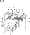
- Figur 1
- eine perspektivische Ansicht der Vorrichtung,
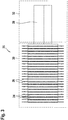
- Figur 2
- die Schneidvorrichtung mit Halter, Schneidmittel und Schneidwelle bei einem Maximalabstand der Schneidmittel,
- Figur 3
- die Schneidvorrichtung gemäß
Figur 2 bei einem Minimalabstand der Schneidmittel, - Figur 4
- eine erste Variante zum lösbaren Klemmen des Schneidmittels in einer perspektivischen Ansicht und zugehörigem Schnitt durch Schneidmittel und Halter,
- Figur 5
- die erste Variante gemäß
Figur 4 zusammen mit einer Klemmwelle im Schnitt, - Figur 6
- eine weitere Variante zum lösbaren Klemmen der Schneidmittel in einer perspektivischen Ansicht sowie
- Figur 7 und 8
- eine schematische Darstellung der Variante gemäß
Figur 6 mit einem Greifer in unterschiedlichen Positionen zum Lösen und Klemmen. - Eine Vorrichtung 8 zum Schneiden eines Produkts, insbesondere aus Süßwarenmasse, umfasst zumindest eine Transporteinrichtung 10. Die Transporteinrichtung 10 ist beispielsweise als Transportband ausgebildet. Die Transporteinrichtung 10 führt einen zu schneidenden Produktteppich in Transportrichtung 11 einer Schneidvorrichtung 25 zu. Das geschnittene Produkt wird durch eine weitere Transporteinrichtung 14 von der Schneidvorrichtung 25 zur Weiterverarbeitung entfernt.
- Die Schneidvorrichtung 25 umfasst mehrere Schneidmittel 26, insbesondere ein Schneidmesser, die auf einer Schneidwelle 28 angeordnet sind. Die Schneidmittel 26 sind beispielsweise ringförmig ausgebildet. Die Schneidkante weist einen in der Regel spitz zulaufenden Abschnitt auf, um in geeigneter Weise das Produkt in Transportrichtung 11 in Streifen zu schneiden. Hierzu können die Schneidmittel 26 zusammen mit der Schneidwelle 28 rotieren.
- Das Schneidmittel 26 ist jeweils durch einen Halter 24 verschiebbar mit der Schneidwelle 28 fixiert. Ist der Halter 24 gelöst, kann das Schneidmittel 26 entlang der Schneidwelle 28 verschoben werden. Ist der Halter 24 fixiert, so bewegt sich das Schneidmittel 26 zusammen mit der rotierenden Schneidwelle 28. Der Halter 24 ist beispielsweise ringförmig bzw. hülsenförmig ausgebildet und stellt die Verbindung her zwischen der Schneidwelle 28 und dem Schneidmittel 26. Das Schneidmittel 26 ist fest mit dem Halter 24 verbunden. Insbesondere die Breite des vorzugsweise ringförmigen Halters 24 ist üblicherweise etwas breiter gewählt als die Breite des Schneidmittels 26, um eine sichere lösbare Verbindung mit der Schneidwelle 28 zu gewährleisten. Außerdem dient der Halter 24 als Greiffläche für einen Greifer 20 zum Bewegen des Halters 24 mit Schneidmittel 26. Die Schneidwelle 28 ist quer zur Transportrichtung 11 angeordnet. Die Schneidmittel 26 mit der zugehörigen Schneidkante sind parallel zur Transportrichtung 11 ausgerichtet. Der Abstand zweier benachbarter Schneidmittel 26 definiert die Breite des Produktstrangs bzw. die Produktstrangbreite.
- Parallel zur Schneidwelle 28 ist ein Gegenhalter 12 angeordnet. Zwischen dem Gegenhalter 12 und den Schneidkanten der Schneidmittel 26 kommt das zu schneidende Produkt bzw. der Produktteppich zu liegen. Der Gegenhalter 12 kann beispielsweise als Gegenschnittwalze oder als Platte ausgeführt sein, über die das Produkt geführt wird. Der Gegenhalter 12 erstreckt sich quer zur Transportrichtung 11 über die gesamte Breite der Transporteinrichtung 10 bzw. 14.
- Entlang einer Führung 16 lässt sich ein Schlitten 18 bewegen. Der Schlitten 18 lässt sich vorzugsweise parallel zur Achse der Schneidwelle 28 und somit quer zur Transportrichtung 11 bewegen. Die Führung 16 ist beispielsweise als Führungsstange bzw. zwei oder mehrere, parallel zueinander und auch parallel zu der Schneidwelle 28 positionierte Führungsstangen ausgebildet. Im Ausführungsbeispiel befindet sich die Führung 16 oberhalb der Schneidwelle 28. Diese könnte jedoch auch seitlich oder nach Platzverhältnissen an einer anderen geeigneten Stelle angeordnet sein. An dem Schlitten 18 ist zumindest ein Greifer 20 mit einem bewegbaren Greifarm 22 angeordnet. Der Greifer 20 mit daran befestigtem Greifam 22 lässt sich durch den Schlitten 18 in eine geeignete Position verfahren, um das einzelne Schneidmittel 26 mit zugehörigem Halter 24 relativ zu der Schneidwelle 28 zu verschieben. Die beschriebenen Komponenten Führung 16, Schlitten 18, Greifer 20, Greifarm 22 bilden eine Verstelleinrichtung 15 zur Verstellung des Schneidmittels 26 relativ zur Schneidwelle 28, insbesondere in axialer Richtung der Schneidwelle 28. Darüber hinaus kann die Verstelleinrichtung 15 auch dazu eingerichtet sein, den Halter 24 und/oder das Schneidmittel 26 relativ zu der Schneidwelle 28 beispielsweise in einer Bewegung um die Achse der Schneidwelle 28 zu bewegen, beispielsweise rotierend. Weiterhin kann die Verstelleinrichtung 15 dazu dienen, einen Mechanismus am Halter 24 und/oder Schneidmittel 26 zu betätigen, um beispielsweise ein Klemmen oder Lösen des Halters 24 relativ zu der Schneidwelle 28 zu ermöglichen.
- Prinzipiell gibt es bei der Vorrichtung 8 zwei unterschiedliche Bereiche 30, 32, in denen sich die Schneidmittel 26 befinden. Befindet sich das Schneidmittel 26 im Wesentlichen im Bereich der Transporteinrichtung 10 bzw. das Schneidmittel 26 kann auf das von der Transporteinrichtung 10 bewegte Produkt einwirken, so befindet sich das Schneidmittel 26 in einem Produktionsbereich 30. Kann das Schneidmittel 26 nicht auf das Produkt einwirken, befindet sich das Schneidmittel in einem Parkbereich 32. Der Parkbereich 32 zeichnet sich dadurch aus, dass die Schneidwelle 28 in diesem Bereich nicht oberhalb der Transporteinrichtung 10 angeordnet ist, sondern seitlich. In dem Parkbereich 32 werden diejenigen Schneidmittel 26 positioniert, die nicht für den momentanen Produktionsprozess benötigt werden, die sich also nicht im Produktionsbereich 30 befinden sollen.
- In den
Figuren 4 und5 ist eine erste Variante zum lösbaren Klemmen der einzelnen Schneidmittel 26 mit Hilfe einer Fixiereinrichtung 33 näher gezeigt. Das Schneidmittel 26 ist über einen Ring 38 mit dem Halter 24 beispielsweise durch Schraubverbindungen befestigt wie dem Schnitt inFigur 4 zu entnehmen. - Wie in
Figur 5 gezeigt ist zumindest eine Keilwelle 34 vorgesehen. Die Keilwelle 34 ist mit der Schneidwelle 28 fest verbunden. Alternativ kann die Keilwelle 34 Bestandteil der Schneidwelle 28 sein. Die Keilwelle 34 ist beispielsweise im Wesentlichen zylinderförmig ausgeführt, wobei der Außendurchmesser der Keilwelle 34 nicht über alle Bereiche konstant verläuft, sondern nimmt entlang des Umfangs keilförmig zu. Im Anschluss an den keilförmigen Bereich 37 nimmt die Außenkontur wieder radial ab. Im Anschluss daran nimmt sie wieder in Form eines weiteren keilförmigen Bereichs 37 radial zu. Beispielhaft sind drei keilförmige Bereiche 37 vorgesehen. Die Außenkontur der Keilwelle 34 wirkt zusammen mit dem Halter 24. - Auch die Innenkontur des Halters 24 weist keilförmige Bereiche 37 auf, die mit den keilförmigen Bereichen 37 der Keilwelle 34 reibschlüssig zusammenwirken. Die Anzahl der keilförmigen Bereiche 37 des Halters 24 entspricht derjenigen der Keilwelle 34. Auch die Geometrie der keilförmigen Bereiche 37 des Halters 24 ähnelt derjenigen der Keilwelle 34. Ein Fixieren bzw. ein Lösen des Schneidmittels 26 relativ zur Schneidwelle 28 wird möglich durch eine Relativbewegung des Halters 24 gegenüber der Keilwelle 34. Durch die Klemmwirkung der keilförmigen Bereiche 37 von Keilwelle 34 und Halter 24 erfolgt das Fixieren. Eine gegenläufige Bewegung von Keilwelle 34 und Halter 24 führt zum Lösen der Fixierung, sodass eine Verschiebung des Halters 24 entlang der Keilwelle 34 bzw. Schneidwelle 28 möglich wird.
- Durch eine entgegengesetzte Drehbewegung von Halter 24 zu Keilwelle 34 erfolgt ein Lösen des Schneidmittels 26 von der Schneidwelle 28, um eine Verschiebung des Schneidmittels 26 in axialer Richtung der Schneidwelle 28 zu ermöglichen. Die Erzeugung der Relativbewegung kann erfolgen wie bereits oben beschrieben. Hierzu greift der Greifer 20 den überstehenden Teil des Halters 24 und fixiert ihn. Anschließend vollzieht die Keilwelle 34 bzw. Schneidwelle 28 eine entsprechende kurze Drehbewegung, um die Klemmwirkung der keilförmigen Bereiche 37 lösen. Ein Klemmen wird durch eine entsprechende gegengesetzte Bewegung der Keilwelle 34 bzw. Schneidwelle 28 relativ zu dem Halter 24 bewirkt.
- In dem Ausführungsbeispiel gemäß den
Figuren 4 und5 bilden die Keilwelle 34 sowie die keilförmigen Bereiche 37 sowohl an der Keilwelle 34 wie auch an dem Halter 24 die Fixiereinrichtung 33. Die Betätigung der Fixiereinrichtung 33 erfolgt wie beschrieben über ein Aufbringen einer Relativbewegung zwischen Keilwelle 34 bzw. Schneidwelle 28 und den keilförmigen Bereichen 37 an dem Halter 24. - In einem alternativen Ausführungsbeispiel gemäß den
Figuren 6 bis 8 kann eine Klemmung des Schneidmittels 26 relativ zur Schneidwelle 28 unter Verwendung der Fixiereinrichtung 33 durch das Vorsehen eines Klemmarms 40 im Zusammenwirken mit dem Halter 24 erfolgen. An dem Klemmarm 40 wie auch an dem Halter 24 sind jeweils radial nach außen ragende Stege 42 angeordnet. Durch eine Relativbewegung des Halters 24 relativ zum Klemmarm 40 kann die Klemmung des Schneidmittels 26 bzw. Halters 24 relativ zur Schneidwelle 28 vorgenommen oder aufgehoben werden. Eine Betätigung des Klemmarms 40 erfolgt, indem der Greifarm 22 des Greifers 20 sowohl mit der Oberseite des Halters 24 und mit dem Klemmarm 40 in Kontakt kommt wie auch die beiden Stege 42 zugleich zusammendrückt wie denFiguren 7 und 8 zu entnehmen. Dadurch löst sich der Klemmmechanismus, indem so beispielsweise eine über den Klemmarm 40 oder einen sonstigen Klemmmechanismus bewirkte Klemmung des Halters 24 relativ zur Schneidwelle 28 aufgehoben wird. Zusätzlich kann eine Passfeder zur Drehmomentübertragung verwendet werden. - Bei dem Ausführungsbeispiel gemäß den
Figuren 6-8 wird die Fixiereinrichtung 33 gebildet durch den Klemmarm 40 sowie den weiteren Arm am Halter 24, sowie gegebenenfalls durch Klemmmittel wie beispielsweise die nicht gezeigte Passfeder oder Ähnliches. Die Aktivierung dieser Fixiereinrichtung 33 erfolgt durch Betätigung der Stege 42. Zugleich hält der Greifer 20 den Klemmarm 40 bzw. den Arm am Halter 24, um die Fixiereinrichtung 33 zu aktivieren. - Ein Klemmen der Fixiereinrichtung 33 bewirkt eine feste Verbindung zwischen Schneidmittel 26 und Schneidwelle 28. Ein Lösen der Fixiereinrichtung 33 bewirkt eine Verschiebbarkeit des Schneidmittel 26 entlang der Schneidwelle 28.
- Die beschriebene Vorrichtung 8 arbeitet wie folgt. Bevor eine neue Produktstrangbreite eingestellt wird, wird von einem in einer Steuerung hinterlegten Programm geprüft, ob eine Verstellung aller Schneidmittel 26 oder nur einzelner Schneidmittel 26 notwendig ist. Ist eine Verstellung aller Schneidmittel 26 notwendig, so werden zunächst diejenigen Schneidmittel 26 in den Parkbereich 32 gefahren, die nicht benötigt werden. Anschließend werden die zu verwendenden Schneidmittel 26 einzeln auf die jeweilige Position verfahren. Die Positionen können frei gewählt werden und somit unterschiedlich sein.
- Die Schneidmittel 26 können automatisch, einzeln und stufenlos auf die gewünschte Produktbreite eingestellt und einzeln an der Schneidwelle 28 fixiert werden. Je nach der Geometrie der Halter 24 können unterschiedliche Breiten, beispielsweise zwischen 14 mm bis 200 mm eingestellt werden. Die Einstellung der Produktbreite kann manuell am Bedienpanel vorgenommen werden. Alternativ könnte die Breite über ein Programm beispielsweise mit einer Rezeptverwaltung gekoppelt sein. Über einen Soll-Ist-Vergleich wird die gewünschte Position angefahren. Die Einstellung der Position der Schneidmittel 26 kann sowohl im Betriebszustand wie auch im Ruhezustand der Vorrichtung 8 erfolgen.
- Zunächst werden die einzelnen Schneidmittel 26 gelöst, indem der Halter 24 nur noch verschiebbar, nicht mehr jedoch fest mit der Schneidwelle 28 verbunden ist. Zum Verschieben der Schneidmittel 26 ist der Greifer 20 mit zugehörigem Greifarm 22 vorgesehen. Hierzu bewegt der Schlitten 18 den Greifer 20 bzw. Greifarm 22 über das zu verschiebende Schneidmittel 26. Die Position wird über ein entsprechendes Wegmessverfahren erkannt. Der Greifarm 22 ist mit dem Greifer 20 verbunden, der beispielsweise als elektromechanischer Klemmgreifer ausgeführt ist. Der Greifer 20 führt eine Greifbewegung des Greifarms 22 mit einer vordefinierten Spannkraft aus und greift das einzelne Schneidmittel 26 bzw. den zugehörigen Halter 24, um dieses zu verfahren. Zunächst wird die Klemmung des Halters 24 mit der Schneidwelle 28 wie beispielhaft in den
Figuren 4-7 ausgeführt gelöst. Die Positionierung des Greifers 20 erfolgt mittels einer spielfreien Führung 16. Für jedes einzelne Schneidmittel 26 erfolgt nun die genaue Positionierung durch den Greifer 20 an der gewünschten Position an der Schneidwelle 28 im Produktionsbereich 30. In der gewünschten Position wird die Klemmung des Halters 24 mit der Schneidwelle 28 wieder vorgenommen. Der Vorgang wiederholt sich für sämtliche gewünschte Schneidmittel 26. Nicht benötigte Schneidmittel 26 werden platzsparend ohne Abstand der Schneidmittel 26 bzw. der zugehörigen Halter 24 zueinander in dem Parkbereich 32 der Vorrichtung 8 geparkt, bis diese später wieder zum Einsatz kommen. Der Parkbereich 32 ist außerhalb des Produktionsbereichs 30. Ebenso ist es möglich, dass ein aktuell verwendetes Schneidmittel 26 gegen ein parkendes Schneidmittel 26 beispielsweise aufgrund von Verschleißerscheinungen ausgetauscht wird. - Jedes Schneidmittel 26 ist auf einem separaten Halter 24 montiert. Der Halter 24 ist vorzugsweise als Klemmhalter ausgebildet. Das Klemmen des Halters 24 kann eine kraftschlüssige, formschlüssige oder kraft-formschlüssige Verbindung sein. So könnte eine Klemmverbindung zwischen Halter 24 und Schneidwelle 28 über eine Keilwelle 34 erfolgen, wie bereits in Verbindung mit den
Figuren 4 und5 erläutert. Dies könnte über eine Welle/Nabe-Verbindung unter Verwendung von aufeinander abgestimmten, miteinander in der Verbindung tretenden Keilprofilen 37, die durch gegenseitiges Verdrehen in Reibschluss gebracht werden. Die Verdrehung des Halters 24 relativ zu der Schneidwelle 28 kann beispielsweise durch eine Drehbewegung der Schneidwelle 28 in Verbindung mit einem die Schneidwelle 28 antreibenden Motor aufgebracht werden. In diesem Fall hält der Greifer 20 bzw. der Greifarm 22 den Halter 24 unmittelbar oder über das Schneidmittel 26, während die Schneidwelle 28 beispielsweise drehmomentgesteuert eine rotatorische Bewegung aufbringt, bis das Schneidmittel 26 gelöst bzw. geklemmt ist. - Alternativ könnte der Greifarm 22 selbst eine Verdrehung des Halters 24 relativ zur Schneidwelle 28 vornehmen. Hierbei muss die Schneidwelle 28 starr sein, während der Greifarm 22 eine rotatorische Bewegung ausführt. In dieser Variante wird über eine Vorspannung kraft- oder kraft-formschlüssig geklemmt, abhängig von der auftretenden Kraft. Hierbei kann ein Halter 24 bzw. ein Klemmhalter mit Vorspannung verwendet werden. Über den Greifarm 22 lässt sich der Halter 24 in axialer Richtung (bezogen auf die Schneidwelle 28) verschieben. Um dies zu ermöglichen, wird eine definierte Kraft vom Greifarm 22 auf den Halter 24 übertragen, die höher ist als die Vorspannkraft.
- Die beschriebene Vorrichtung eignet sich insbesondere zum Schneiden von Produkten, insbesondere im Süßwarenbereich wie beispielsweise zur Herstellung von Süßwarenriegel, Kaugummimassen, Karamellen oder Bonbons. Die Verwendung ist jedoch hierauf nicht eingeschränkt.
Claims (14)
- Vorrichtung zum Schneiden eines Produkts, umfassend zumindest eine Transporteinrichtung (10) zum Transport des zu schneidenden Produkts, zumindest eine Schneidvorrichtung (25), umfassend mehrere Schneidmittel (26), die auf zumindest einer Schneidwelle (28) angeordnet sind, dadurch gekennzeichnet, dass zumindest eine Verstelleinrichtung (15) vorgesehen ist zum Verschieben des Schneidmittels (26) entlang der Schneidwelle (28).
- Vorrichtung nach einem der vorhergehenden Ansprüche, dadurch gekennzeichnet, dass zumindest eine Fixiereinrichtung (33) vorgesehen ist zum lösbaren Fixieren des Schneidmittels (26) an der Schneidwelle (28).
- Vorrichtung nach einem der vorhergehenden Ansprüche, dadurch gekennzeichnet, dass die Verstelleinrichtung (15) eingerichtet ist zum Lösen oder Fixieren des Schneidmittels (26) an der Schneidwelle (28) auf die Fixiereinrichtung (33).
- Vorrichtung nach einem der vorhergehenden Ansprüche, dadurch gekennzeichnet, dass die Verstelleinrichtung (15) dazu ausgebildet ist, zumindest einen Greifer (20) zu dem Schneidmittel (26) zu bewegen, das Schneidmittel (26) und/oder einen mit dem Schneidmittel (26) verbundenen Träger (24) zu greifen, und den Greifer (20) mit dem Schneidmittel (26) entlang der Schneidwelle (28) zu bewegen.
- Vorrichtung nach einem der vorhergehenden Ansprüche, dadurch gekennzeichnet, dass zum Lösen oder Fixieren des Schneidmittels (26) bezüglich der Schneidwelle (28) die Verstelleinrichtung (15) und/oder die Schneidwelle (28) dazu ausgebildet sind/ist, eine Relativbewegung zwischen Schneidmittel (26) und Schneidwelle (28) zu erzeugen.
- Vorrichtung nach einem der vorhergehenden Ansprüche, dadurch gekennzeichnet, dass die Verstelleinrichtung (15) zumindest einen Greifer (20) und/oder zumindest einen Greifarm (22) und/oder einen Schlitten (18) und/oder eine Führung (16) aufweist.
- Vorrichtung nach einem der vorhergehenden Ansprüche, dadurch gekennzeichnet, dass die Fixiereinrichtung (33) zumindest eine Keilwelle (34), insbesondere als Bestandteil der Schneidwelle (28), und/oder zumindest einen keilförmigen Bereich (37) an der Keilwelle (34) und/oder an einem Träger (24) des Schneidmittels (26) und/oder zumindest einen Klemmarm (40) und/oder zumindest einen Steg (42) zum Betätigen eines Klemmarms (40) umfasst.
- Vorrichtung nach einem der vorhergehenden Ansprüche, dadurch gekennzeichnet, dass zumindest ein Parkbereich (32) vorgesehen ist zur Aufnahme solcher Schneidmittel (26), die nicht zum Schneiden des Produkts benötigt werden.
- Verfahren zum Schneiden eines Produkts, wobei eine Transporteinrichtung (10) ein zu schneidendes Produkt zu einer Schneidvorrichtung (25) transportiert, wobei mehrere Schneidmittel (26) auf zumindest einer Schneidwelle (28) angeordnet sind, dadurch gekennzeichnet, dass zumindest eine Verstelleinrichtung (15) zumindest ein Schneidmittel (26) entlang der Schneidwelle (28) verschiebt.
- Verfahren nach dem vorhergehenden Verfahrensanspruch, dadurch gekennzeichnet, dass zunächst eine Fixiereinrichtung (33) gelöst wird, die das Schneidmittel (26) mit der Schneidwelle (28) lösbar fixiert, anschließend die Schneidvorrichtung (25) entlang der Schneidwelle (28) verschoben wird und anschließend das Schneidmittel (26) wieder durch die Fixiereinrichtung (33) mit der Schneidwelle (28) fixiert wird.
- Verfahren nach einem der vorhergehenden Verfahrensansprüche, dadurch gekennzeichnet, dass die Verstelleinrichtung (15) zum Lösen oder Fixieren des Schneidmittels (26) an der Schneidwelle (28) auf die Fixiereinrichtung (33) einwirkt.
- Verfahren nach einem der vorhergehenden Verfahrensansprüche, dadurch gekennzeichnet, dass zunächst ein Greifer (20) zu dem Schneidmittel (26) bewegt wird, anschließend das Schneidmittel (26) und/oder einen mit dem Schneidmittel (26) verbundenen Träger (24) durch den Greifer (20) gegriffen wird und anschließend der Greifer (20) mit dem Schneidmittel (26) entlang der Schneidwelle (28) bewegt wird.
- Verfahren nach einem der vorhergehenden Verfahrensansprüche, dadurch gekennzeichnet, dass die Verstelleinrichtung (15) zumindest ein nicht für den Produktionsprozess benötigtes Schneidmittel (26) in einen Parkbereich (32) bringt.
- Verfahren nach einem der vorhergehenden Verfahrensansprüche, dadurch gekennzeichnet, dass zum Lösen oder Fixieren des Schneidmittels (26) bzw. des Halters (24) an der Schneidwelle (28) die Verstelleinrichtung (15) und/oder die Schneidwelle (28) eine Relativbewegung zwischen dem Schneidmittel (26) bzw. dem Halter (24) und der Schneidwelle (28) erzeugt.
Applications Claiming Priority (1)
| Application Number | Priority Date | Filing Date | Title |
|---|---|---|---|
| DE102018206641.8A DE102018206641A1 (de) | 2018-04-27 | 2018-04-27 | Vorrichtung und Verfahren zum Schneiden eines Produkts, insbesondere aus Süßwarenmasse |
Publications (2)
| Publication Number | Publication Date |
|---|---|
| EP3560668A1 true EP3560668A1 (de) | 2019-10-30 |
| EP3560668B1 EP3560668B1 (de) | 2021-02-17 |
Family
ID=65635493
Family Applications (1)
| Application Number | Title | Priority Date | Filing Date |
|---|---|---|---|
| EP19159884.6A Active EP3560668B1 (de) | 2018-04-27 | 2019-02-28 | Vorrichtung und verfahren zum schneiden eines produkts aus süsswarenmasse |
Country Status (4)
| Country | Link |
|---|---|
| EP (1) | EP3560668B1 (de) |
| DE (1) | DE102018206641A1 (de) |
| DK (1) | DK3560668T3 (de) |
| ES (1) | ES2875554T3 (de) |
Cited By (2)
| Publication number | Priority date | Publication date | Assignee | Title |
|---|---|---|---|---|
| WO2021204866A1 (de) * | 2020-04-07 | 2021-10-14 | Hansella Gmbh | Schneidvorrichtung, schneidsystem mit der schneidvorrichtung und verfahren zum einstellen eines schnittabstands |
| CN115847530A (zh) * | 2022-12-29 | 2023-03-28 | 苏州市星辰科技有限公司 | 一种pet防污抗菌硬化膜加工装置及加工方法 |
Families Citing this family (1)
| Publication number | Priority date | Publication date | Assignee | Title |
|---|---|---|---|---|
| DE102024130617A1 (de) * | 2024-10-21 | 2026-04-23 | EVOBEND GmbH | Schneidvorrichtung zum Schneiden von Flachmaterial |
Citations (7)
| Publication number | Priority date | Publication date | Assignee | Title |
|---|---|---|---|---|
| US3837265A (en) * | 1972-12-18 | 1974-09-24 | Rengo Co Ltd | Device for securing slitter or scorer head |
| US4054394A (en) * | 1976-12-01 | 1977-10-18 | Dovey Manufacturing Company | Quick release locking device |
| US4577440A (en) * | 1983-06-21 | 1986-03-25 | Erwin Junker | Clamping device for a grinding ring |
| DE3836503A1 (de) * | 1988-10-26 | 1990-05-03 | Bhs Bayerische Berg | Verfahren zum positionieren von werkzeugen einer laengsschneide- und/oder rillmaschine sowie vorrichtung zur durchfuehrung dieses verfahrens |
| NL1018896C2 (nl) * | 2001-09-06 | 2003-03-07 | Buhrs E Fulfillment Systems B | Inrichting voor het aanbrengen van rillen, perforaties of snedes in een substraat, zoals bijvoorbeeld papier, karton of folie. |
| WO2003101685A1 (en) * | 2002-05-30 | 2003-12-11 | Blue Ip, Inc. | Cnc slitter machine |
| EP1094717B1 (de) | 1999-05-05 | 2006-04-05 | Robert Bosch Gmbh | Vorrichtung zum abtrennen von einzelstücken von einem kontinuierlich bewegten massestrang |
Family Cites Families (10)
| Publication number | Priority date | Publication date | Assignee | Title |
|---|---|---|---|---|
| DE703888C (de) * | 1938-06-10 | 1941-03-19 | Richard Nicolaus | Vorrichtung zum Befestigen der Kreismesser von Papierschneidemaschinen auf der Messerwelle mittels Naben |
| DE9410069U1 (de) * | 1994-06-22 | 1994-09-15 | Dienes Werke für Maschinenteile GmbH & Co KG, 51491 Overath | Positioniereinrichtung für Untermesser bei Längsschneidemaschinen |
| GB9504291D0 (en) * | 1995-03-03 | 1995-04-19 | Bartingale Peter | Improvements in adjustable clamping between two tubes |
| JP3980678B2 (ja) * | 1996-03-08 | 2007-09-26 | 富士フイルム株式会社 | 刃物位置切り替え制御方法 |
| JP2000205220A (ja) * | 1999-01-21 | 2000-07-25 | Suehiro Kogyo Kk | 管状機構 |
| US20030209115A1 (en) * | 2002-05-07 | 2003-11-13 | Burkart Arthur P. | Apparatus and method for positioning tool heads in spaced linear array |
| DE202005005071U1 (de) * | 2004-10-25 | 2005-06-16 | DIENES WERKE FüR MASCHINENTEILE GMBH & CO. KG | Längsschneidemaschine mit Einstellhilfe für die Messerposition |
| DE102006055902A1 (de) * | 2006-11-27 | 2008-07-31 | Düspohl Maschinenbau Gmbh | Verfahren zum Positionieren von Messern einer Schneidvorrichtung und zugehörige Schneidvorrichtung |
| US8210079B2 (en) * | 2007-09-14 | 2012-07-03 | L&P Property Management Company | Programmable border slitter |
| DE102014110081A1 (de) * | 2014-07-17 | 2016-01-21 | Josef Bäumer | Ringmessermodul und Längsschneidsystem |
-
2018
- 2018-04-27 DE DE102018206641.8A patent/DE102018206641A1/de active Pending
-
2019
- 2019-02-28 DK DK19159884.6T patent/DK3560668T3/da active
- 2019-02-28 ES ES19159884T patent/ES2875554T3/es active Active
- 2019-02-28 EP EP19159884.6A patent/EP3560668B1/de active Active
Patent Citations (7)
| Publication number | Priority date | Publication date | Assignee | Title |
|---|---|---|---|---|
| US3837265A (en) * | 1972-12-18 | 1974-09-24 | Rengo Co Ltd | Device for securing slitter or scorer head |
| US4054394A (en) * | 1976-12-01 | 1977-10-18 | Dovey Manufacturing Company | Quick release locking device |
| US4577440A (en) * | 1983-06-21 | 1986-03-25 | Erwin Junker | Clamping device for a grinding ring |
| DE3836503A1 (de) * | 1988-10-26 | 1990-05-03 | Bhs Bayerische Berg | Verfahren zum positionieren von werkzeugen einer laengsschneide- und/oder rillmaschine sowie vorrichtung zur durchfuehrung dieses verfahrens |
| EP1094717B1 (de) | 1999-05-05 | 2006-04-05 | Robert Bosch Gmbh | Vorrichtung zum abtrennen von einzelstücken von einem kontinuierlich bewegten massestrang |
| NL1018896C2 (nl) * | 2001-09-06 | 2003-03-07 | Buhrs E Fulfillment Systems B | Inrichting voor het aanbrengen van rillen, perforaties of snedes in een substraat, zoals bijvoorbeeld papier, karton of folie. |
| WO2003101685A1 (en) * | 2002-05-30 | 2003-12-11 | Blue Ip, Inc. | Cnc slitter machine |
Cited By (3)
| Publication number | Priority date | Publication date | Assignee | Title |
|---|---|---|---|---|
| WO2021204866A1 (de) * | 2020-04-07 | 2021-10-14 | Hansella Gmbh | Schneidvorrichtung, schneidsystem mit der schneidvorrichtung und verfahren zum einstellen eines schnittabstands |
| CN115847530A (zh) * | 2022-12-29 | 2023-03-28 | 苏州市星辰科技有限公司 | 一种pet防污抗菌硬化膜加工装置及加工方法 |
| CN115847530B (zh) * | 2022-12-29 | 2024-04-09 | 浙江凡特科新材料有限公司 | 一种pet防污抗菌硬化膜加工装置及加工方法 |
Also Published As
| Publication number | Publication date |
|---|---|
| DK3560668T3 (da) | 2021-05-25 |
| EP3560668B1 (de) | 2021-02-17 |
| ES2875554T3 (es) | 2021-11-10 |
| DE102018206641A1 (de) | 2019-10-31 |
Similar Documents
| Publication | Publication Date | Title |
|---|---|---|
| DE60214425T2 (de) | Cnc-bahnschlitzmaschine | |
| DE112017004840B4 (de) | Rotative Abisoliervorrichtung | |
| DE19547005C2 (de) | Drahtformvorrichtung | |
| DE3045095A1 (de) | Vorrichtung zum abstreifen von abfallstuecken von zuschnitten | |
| CH659203A5 (de) | Scherschneidemaschine. | |
| WO1997017751A1 (de) | Abisoliervorrichtung | |
| EP3560668B1 (de) | Vorrichtung und verfahren zum schneiden eines produkts aus süsswarenmasse | |
| DE2507449A1 (de) | Maschinenschere | |
| DE102021120316A1 (de) | Verpackungsmaschine mit einer Vorrichtung zum Zuschneiden von Lebensmittelverpackungen entlang einer Längsrichtung | |
| EP2127828B1 (de) | Vorrichtung zum Abtrennen eines Nutzenstapels von einem Ausgangsstapel durch Schneiden | |
| EP0602593B1 (de) | Einrichtung zum Beschneiden von flächigen Erzeugnissen, insbesondere mehrblättrigen Druckerzeugnissen | |
| DE69400542T2 (de) | Papierschneidvorrichtung | |
| EP0602594B1 (de) | Einrichtung zum Beschneiden von flächigen Erzeugnissen, insbesondere mehrblättrigen Druckerzeugnissen | |
| DE69212199T2 (de) | Gerät zum Trennen von gestanzten Bögen | |
| DE3029143C2 (de) | Rotierende Stanzvorrichtung | |
| EP1593467B1 (de) | Vorrichtung zum Handhaben eines Stapels | |
| EP3645226B1 (de) | Querschneideeinrichtung und verfahren zur stabilisierung einer schnittkante beim quetschschnitt | |
| EP3505355A1 (de) | Abschneidevorrichtung fuer endlosetiketten | |
| DE2446776C2 (de) | Verfahren zur Herstellung einer geteilten Futtermutter für ein Bohrfutter | |
| DE10261968A1 (de) | Verfahren zur Herstellung eines Mitnehmerelements | |
| EP4438254A2 (de) | Vorrichtung zum zuschneiden von verpackungen | |
| WO2011023256A1 (de) | Antriebsmotor | |
| EP1782930A1 (de) | Verfahren und Vorrichtung zum Beschneiden von Druckprodukten | |
| EP2676558B1 (de) | Vorrichtung zum Trennen eines endlosen zugeführten Stranges eines Produktes der Tabak verarbeitenden Industrie in einzelne Stäbe | |
| DE19920099B4 (de) | Positioniervorrichtung für Sägeblätter |
Legal Events
| Date | Code | Title | Description |
|---|---|---|---|
| PUAI | Public reference made under article 153(3) epc to a published international application that has entered the european phase |
Free format text: ORIGINAL CODE: 0009012 |
|
| STAA | Information on the status of an ep patent application or granted ep patent |
Free format text: STATUS: THE APPLICATION HAS BEEN PUBLISHED |
|
| AK | Designated contracting states |
Kind code of ref document: A1 Designated state(s): AL AT BE BG CH CY CZ DE DK EE ES FI FR GB GR HR HU IE IS IT LI LT LU LV MC MK MT NL NO PL PT RO RS SE SI SK SM TR |
|
| AX | Request for extension of the european patent |
Extension state: BA ME |
|
| STAA | Information on the status of an ep patent application or granted ep patent |
Free format text: STATUS: REQUEST FOR EXAMINATION WAS MADE |
|
| RAP1 | Party data changed (applicant data changed or rights of an application transferred) |
Owner name: ROBERT BOSCH GMBH |
|
| 17P | Request for examination filed |
Effective date: 20200409 |
|
| RBV | Designated contracting states (corrected) |
Designated state(s): AL AT BE BG CH CY CZ DE DK EE ES FI FR GB GR HR HU IE IS IT LI LT LU LV MC MK MT NL NO PL PT RO RS SE SI SK SM TR |
|
| GRAP | Despatch of communication of intention to grant a patent |
Free format text: ORIGINAL CODE: EPIDOSNIGR1 |
|
| STAA | Information on the status of an ep patent application or granted ep patent |
Free format text: STATUS: GRANT OF PATENT IS INTENDED |
|
| INTG | Intention to grant announced |
Effective date: 20201016 |
|
| RAP1 | Party data changed (applicant data changed or rights of an application transferred) |
Owner name: SYNTEGON TECHNOLOGY GMBH |
|
| GRAS | Grant fee paid |
Free format text: ORIGINAL CODE: EPIDOSNIGR3 |
|
| GRAA | (expected) grant |
Free format text: ORIGINAL CODE: 0009210 |
|
| STAA | Information on the status of an ep patent application or granted ep patent |
Free format text: STATUS: THE PATENT HAS BEEN GRANTED |
|
| AK | Designated contracting states |
Kind code of ref document: B1 Designated state(s): AL AT BE BG CH CY CZ DE DK EE ES FI FR GB GR HR HU IE IS IT LI LT LU LV MC MK MT NL NO PL PT RO RS SE SI SK SM TR |
|
| REG | Reference to a national code |
Ref country code: GB Ref legal event code: FG4D Free format text: NOT ENGLISH |
|
| REG | Reference to a national code |
Ref country code: CH Ref legal event code: EP |
|
| REG | Reference to a national code |
Ref country code: DE Ref legal event code: R096 Ref document number: 502019000788 Country of ref document: DE |
|
| REG | Reference to a national code |
Ref country code: AT Ref legal event code: REF Ref document number: 1360883 Country of ref document: AT Kind code of ref document: T Effective date: 20210315 |
|
| REG | Reference to a national code |
Ref country code: IE Ref legal event code: FG4D Free format text: LANGUAGE OF EP DOCUMENT: GERMAN |
|
| REG | Reference to a national code |
Ref country code: DK Ref legal event code: T3 Effective date: 20210517 |
|
| REG | Reference to a national code |
Ref country code: NL Ref legal event code: FP |
|
| REG | Reference to a national code |
Ref country code: LT Ref legal event code: MG9D |
|
| PG25 | Lapsed in a contracting state [announced via postgrant information from national office to epo] |
Ref country code: BG Free format text: LAPSE BECAUSE OF FAILURE TO SUBMIT A TRANSLATION OF THE DESCRIPTION OR TO PAY THE FEE WITHIN THE PRESCRIBED TIME-LIMIT Effective date: 20210517 Ref country code: GR Free format text: LAPSE BECAUSE OF FAILURE TO SUBMIT A TRANSLATION OF THE DESCRIPTION OR TO PAY THE FEE WITHIN THE PRESCRIBED TIME-LIMIT Effective date: 20210518 Ref country code: FI Free format text: LAPSE BECAUSE OF FAILURE TO SUBMIT A TRANSLATION OF THE DESCRIPTION OR TO PAY THE FEE WITHIN THE PRESCRIBED TIME-LIMIT Effective date: 20210217 Ref country code: HR Free format text: LAPSE BECAUSE OF FAILURE TO SUBMIT A TRANSLATION OF THE DESCRIPTION OR TO PAY THE FEE WITHIN THE PRESCRIBED TIME-LIMIT Effective date: 20210217 Ref country code: LT Free format text: LAPSE BECAUSE OF FAILURE TO SUBMIT A TRANSLATION OF THE DESCRIPTION OR TO PAY THE FEE WITHIN THE PRESCRIBED TIME-LIMIT Effective date: 20210217 Ref country code: NO Free format text: LAPSE BECAUSE OF FAILURE TO SUBMIT A TRANSLATION OF THE DESCRIPTION OR TO PAY THE FEE WITHIN THE PRESCRIBED TIME-LIMIT Effective date: 20210517 Ref country code: PT Free format text: LAPSE BECAUSE OF FAILURE TO SUBMIT A TRANSLATION OF THE DESCRIPTION OR TO PAY THE FEE WITHIN THE PRESCRIBED TIME-LIMIT Effective date: 20210617 |
|
| RAP2 | Party data changed (patent owner data changed or rights of a patent transferred) |
Owner name: HANSELLA GMBH |
|
| PG25 | Lapsed in a contracting state [announced via postgrant information from national office to epo] |
Ref country code: LV Free format text: LAPSE BECAUSE OF FAILURE TO SUBMIT A TRANSLATION OF THE DESCRIPTION OR TO PAY THE FEE WITHIN THE PRESCRIBED TIME-LIMIT Effective date: 20210217 Ref country code: RS Free format text: LAPSE BECAUSE OF FAILURE TO SUBMIT A TRANSLATION OF THE DESCRIPTION OR TO PAY THE FEE WITHIN THE PRESCRIBED TIME-LIMIT Effective date: 20210217 Ref country code: PL Free format text: LAPSE BECAUSE OF FAILURE TO SUBMIT A TRANSLATION OF THE DESCRIPTION OR TO PAY THE FEE WITHIN THE PRESCRIBED TIME-LIMIT Effective date: 20210217 Ref country code: SE Free format text: LAPSE BECAUSE OF FAILURE TO SUBMIT A TRANSLATION OF THE DESCRIPTION OR TO PAY THE FEE WITHIN THE PRESCRIBED TIME-LIMIT Effective date: 20210217 |
|
| REG | Reference to a national code |
Ref country code: NL Ref legal event code: PD Owner name: HANSELLA GMBH; DE Free format text: DETAILS ASSIGNMENT: CHANGE OF OWNER(S), ASSIGNMENT; FORMER OWNER NAME: SYNTEGON TECHNOLOGY GMBH Effective date: 20210816 |
|
| REG | Reference to a national code |
Ref country code: SK Ref legal event code: T3 Ref document number: E 37799 Country of ref document: SK Ref country code: GB Ref legal event code: 732E Free format text: REGISTERED BETWEEN 20210902 AND 20210908 |
|
| PG25 | Lapsed in a contracting state [announced via postgrant information from national office to epo] |
Ref country code: IS Free format text: LAPSE BECAUSE OF FAILURE TO SUBMIT A TRANSLATION OF THE DESCRIPTION OR TO PAY THE FEE WITHIN THE PRESCRIBED TIME-LIMIT Effective date: 20210617 |
|
| REG | Reference to a national code |
Ref country code: BE Ref legal event code: PD Owner name: HANSELLA GMBH; DE Free format text: DETAILS ASSIGNMENT: CHANGE OF OWNER(S), ASSIGNMENT; FORMER OWNER NAME: SYNTEGON TECHNOLOGY GMBH Effective date: 20210813 |
|
| PG25 | Lapsed in a contracting state [announced via postgrant information from national office to epo] |
Ref country code: SM Free format text: LAPSE BECAUSE OF FAILURE TO SUBMIT A TRANSLATION OF THE DESCRIPTION OR TO PAY THE FEE WITHIN THE PRESCRIBED TIME-LIMIT Effective date: 20210217 Ref country code: CZ Free format text: LAPSE BECAUSE OF FAILURE TO SUBMIT A TRANSLATION OF THE DESCRIPTION OR TO PAY THE FEE WITHIN THE PRESCRIBED TIME-LIMIT Effective date: 20210217 Ref country code: EE Free format text: LAPSE BECAUSE OF FAILURE TO SUBMIT A TRANSLATION OF THE DESCRIPTION OR TO PAY THE FEE WITHIN THE PRESCRIBED TIME-LIMIT Effective date: 20210217 Ref country code: LU Free format text: LAPSE BECAUSE OF NON-PAYMENT OF DUE FEES Effective date: 20210228 |
|
| REG | Reference to a national code |
Ref country code: ES Ref legal event code: FG2A Ref document number: 2875554 Country of ref document: ES Kind code of ref document: T3 Effective date: 20211110 |
|
| REG | Reference to a national code |
Ref country code: DE Ref legal event code: R097 Ref document number: 502019000788 Country of ref document: DE |
|
| PG25 | Lapsed in a contracting state [announced via postgrant information from national office to epo] |
Ref country code: MC Free format text: LAPSE BECAUSE OF FAILURE TO SUBMIT A TRANSLATION OF THE DESCRIPTION OR TO PAY THE FEE WITHIN THE PRESCRIBED TIME-LIMIT Effective date: 20210217 Ref country code: RO Free format text: LAPSE BECAUSE OF FAILURE TO SUBMIT A TRANSLATION OF THE DESCRIPTION OR TO PAY THE FEE WITHIN THE PRESCRIBED TIME-LIMIT Effective date: 20210217 |
|
| PLBE | No opposition filed within time limit |
Free format text: ORIGINAL CODE: 0009261 |
|
| STAA | Information on the status of an ep patent application or granted ep patent |
Free format text: STATUS: NO OPPOSITION FILED WITHIN TIME LIMIT |
|
| 26N | No opposition filed |
Effective date: 20211118 |
|
| PG25 | Lapsed in a contracting state [announced via postgrant information from national office to epo] |
Ref country code: AL Free format text: LAPSE BECAUSE OF FAILURE TO SUBMIT A TRANSLATION OF THE DESCRIPTION OR TO PAY THE FEE WITHIN THE PRESCRIBED TIME-LIMIT Effective date: 20210217 Ref country code: IE Free format text: LAPSE BECAUSE OF NON-PAYMENT OF DUE FEES Effective date: 20210228 |
|
| PG25 | Lapsed in a contracting state [announced via postgrant information from national office to epo] |
Ref country code: SI Free format text: LAPSE BECAUSE OF FAILURE TO SUBMIT A TRANSLATION OF THE DESCRIPTION OR TO PAY THE FEE WITHIN THE PRESCRIBED TIME-LIMIT Effective date: 20210217 |
|
| PG25 | Lapsed in a contracting state [announced via postgrant information from national office to epo] |
Ref country code: IS Free format text: LAPSE BECAUSE OF FAILURE TO SUBMIT A TRANSLATION OF THE DESCRIPTION OR TO PAY THE FEE WITHIN THE PRESCRIBED TIME-LIMIT Effective date: 20210617 |
|
| PG25 | Lapsed in a contracting state [announced via postgrant information from national office to epo] |
Ref country code: CY Free format text: LAPSE BECAUSE OF FAILURE TO SUBMIT A TRANSLATION OF THE DESCRIPTION OR TO PAY THE FEE WITHIN THE PRESCRIBED TIME-LIMIT Effective date: 20210217 |
|
| P01 | Opt-out of the competence of the unified patent court (upc) registered |
Effective date: 20230530 |
|
| PG25 | Lapsed in a contracting state [announced via postgrant information from national office to epo] |
Ref country code: HU Free format text: LAPSE BECAUSE OF FAILURE TO SUBMIT A TRANSLATION OF THE DESCRIPTION OR TO PAY THE FEE WITHIN THE PRESCRIBED TIME-LIMIT; INVALID AB INITIO Effective date: 20190228 |
|
| PG25 | Lapsed in a contracting state [announced via postgrant information from national office to epo] |
Ref country code: MK Free format text: LAPSE BECAUSE OF FAILURE TO SUBMIT A TRANSLATION OF THE DESCRIPTION OR TO PAY THE FEE WITHIN THE PRESCRIBED TIME-LIMIT Effective date: 20210217 |
|
| PG25 | Lapsed in a contracting state [announced via postgrant information from national office to epo] |
Ref country code: MT Free format text: LAPSE BECAUSE OF FAILURE TO SUBMIT A TRANSLATION OF THE DESCRIPTION OR TO PAY THE FEE WITHIN THE PRESCRIBED TIME-LIMIT Effective date: 20210217 |
|
| REG | Reference to a national code |
Ref country code: AT Ref legal event code: MM01 Ref document number: 1360883 Country of ref document: AT Kind code of ref document: T Effective date: 20240228 |
|
| PG25 | Lapsed in a contracting state [announced via postgrant information from national office to epo] |
Ref country code: AT Free format text: LAPSE BECAUSE OF NON-PAYMENT OF DUE FEES Effective date: 20240228 |
|
| PGFP | Annual fee paid to national office [announced via postgrant information from national office to epo] |
Ref country code: ES Payment date: 20250331 Year of fee payment: 7 |
|
| REG | Reference to a national code |
Ref country code: CH Ref legal event code: U11 Free format text: ST27 STATUS EVENT CODE: U-0-0-U10-U11 (AS PROVIDED BY THE NATIONAL OFFICE) Effective date: 20260301 |
|
| PGFP | Annual fee paid to national office [announced via postgrant information from national office to epo] |
Ref country code: NL Payment date: 20260218 Year of fee payment: 8 |
|
| PGFP | Annual fee paid to national office [announced via postgrant information from national office to epo] |
Ref country code: GB Payment date: 20260219 Year of fee payment: 8 |
|
| PGFP | Annual fee paid to national office [announced via postgrant information from national office to epo] |
Ref country code: DE Payment date: 20260218 Year of fee payment: 8 Ref country code: DK Payment date: 20260220 Year of fee payment: 8 |
|
| PGFP | Annual fee paid to national office [announced via postgrant information from national office to epo] |
Ref country code: AT Payment date: 20260410 Year of fee payment: 5 |
|
| PGFP | Annual fee paid to national office [announced via postgrant information from national office to epo] |
Ref country code: BE Payment date: 20260218 Year of fee payment: 8 Ref country code: IT Payment date: 20260224 Year of fee payment: 8 |
|
| PGFP | Annual fee paid to national office [announced via postgrant information from national office to epo] |
Ref country code: FR Payment date: 20260218 Year of fee payment: 8 |
|
| PGFP | Annual fee paid to national office [announced via postgrant information from national office to epo] |
Ref country code: TR Payment date: 20260224 Year of fee payment: 8 |
|
| PGFP | Annual fee paid to national office [announced via postgrant information from national office to epo] |
Ref country code: CH Payment date: 20260301 Year of fee payment: 8 |
|
| PGFP | Annual fee paid to national office [announced via postgrant information from national office to epo] |
Ref country code: SK Payment date: 20260224 Year of fee payment: 8 |