EP3511204A1 - Système de réglage permettant le pivotement d'au moins un composant optique d'un phare de véhicule autour d'un premier et d'un second axes - Google Patents
Système de réglage permettant le pivotement d'au moins un composant optique d'un phare de véhicule autour d'un premier et d'un second axes Download PDFInfo
- Publication number
- EP3511204A1 EP3511204A1 EP18151125.4A EP18151125A EP3511204A1 EP 3511204 A1 EP3511204 A1 EP 3511204A1 EP 18151125 A EP18151125 A EP 18151125A EP 3511204 A1 EP3511204 A1 EP 3511204A1
- Authority
- EP
- European Patent Office
- Prior art keywords
- axis
- holding element
- adjustment system
- pivoting
- holding
- Prior art date
- Legal status (The legal status is an assumption and is not a legal conclusion. Google has not performed a legal analysis and makes no representation as to the accuracy of the status listed.)
- Withdrawn
Links
- 230000008878 coupling Effects 0.000 claims description 28
- 238000010168 coupling process Methods 0.000 claims description 28
- 238000005859 coupling reaction Methods 0.000 claims description 28
- 230000003287 optical effect Effects 0.000 claims description 26
- 238000003384 imaging method Methods 0.000 claims description 18
- 238000006073 displacement reaction Methods 0.000 claims description 11
- 230000007246 mechanism Effects 0.000 description 4
- 238000009826 distribution Methods 0.000 description 3
- 239000011159 matrix material Substances 0.000 description 2
- 230000008901 benefit Effects 0.000 description 1
- 230000015572 biosynthetic process Effects 0.000 description 1
- 229910052736 halogen Inorganic materials 0.000 description 1
- 150000002367 halogens Chemical class 0.000 description 1
- 230000003993 interaction Effects 0.000 description 1
- 230000001105 regulatory effect Effects 0.000 description 1
- 238000007493 shaping process Methods 0.000 description 1
Images


Classifications
-
- B—PERFORMING OPERATIONS; TRANSPORTING
- B60—VEHICLES IN GENERAL
- B60Q—ARRANGEMENT OF SIGNALLING OR LIGHTING DEVICES, THE MOUNTING OR SUPPORTING THEREOF OR CIRCUITS THEREFOR, FOR VEHICLES IN GENERAL
- B60Q1/00—Arrangement of optical signalling or lighting devices, the mounting or supporting thereof or circuits therefor
- B60Q1/02—Arrangement of optical signalling or lighting devices, the mounting or supporting thereof or circuits therefor the devices being primarily intended to illuminate the way ahead or to illuminate other areas of way or environments
- B60Q1/04—Arrangement of optical signalling or lighting devices, the mounting or supporting thereof or circuits therefor the devices being primarily intended to illuminate the way ahead or to illuminate other areas of way or environments the devices being headlights
- B60Q1/06—Arrangement of optical signalling or lighting devices, the mounting or supporting thereof or circuits therefor the devices being primarily intended to illuminate the way ahead or to illuminate other areas of way or environments the devices being headlights adjustable, e.g. remotely-controlled from inside vehicle
- B60Q1/068—Arrangement of optical signalling or lighting devices, the mounting or supporting thereof or circuits therefor the devices being primarily intended to illuminate the way ahead or to illuminate other areas of way or environments the devices being headlights adjustable, e.g. remotely-controlled from inside vehicle by mechanical means
-
- B—PERFORMING OPERATIONS; TRANSPORTING
- B60—VEHICLES IN GENERAL
- B60Q—ARRANGEMENT OF SIGNALLING OR LIGHTING DEVICES, THE MOUNTING OR SUPPORTING THEREOF OR CIRCUITS THEREFOR, FOR VEHICLES IN GENERAL
- B60Q1/00—Arrangement of optical signalling or lighting devices, the mounting or supporting thereof or circuits therefor
- B60Q1/02—Arrangement of optical signalling or lighting devices, the mounting or supporting thereof or circuits therefor the devices being primarily intended to illuminate the way ahead or to illuminate other areas of way or environments
- B60Q1/04—Arrangement of optical signalling or lighting devices, the mounting or supporting thereof or circuits therefor the devices being primarily intended to illuminate the way ahead or to illuminate other areas of way or environments the devices being headlights
- B60Q1/06—Arrangement of optical signalling or lighting devices, the mounting or supporting thereof or circuits therefor the devices being primarily intended to illuminate the way ahead or to illuminate other areas of way or environments the devices being headlights adjustable, e.g. remotely-controlled from inside vehicle
- B60Q1/076—Arrangement of optical signalling or lighting devices, the mounting or supporting thereof or circuits therefor the devices being primarily intended to illuminate the way ahead or to illuminate other areas of way or environments the devices being headlights adjustable, e.g. remotely-controlled from inside vehicle by electrical means including means to transmit the movements, e.g. shafts or joints
-
- B—PERFORMING OPERATIONS; TRANSPORTING
- B60—VEHICLES IN GENERAL
- B60Q—ARRANGEMENT OF SIGNALLING OR LIGHTING DEVICES, THE MOUNTING OR SUPPORTING THEREOF OR CIRCUITS THEREFOR, FOR VEHICLES IN GENERAL
- B60Q1/00—Arrangement of optical signalling or lighting devices, the mounting or supporting thereof or circuits therefor
- B60Q1/02—Arrangement of optical signalling or lighting devices, the mounting or supporting thereof or circuits therefor the devices being primarily intended to illuminate the way ahead or to illuminate other areas of way or environments
- B60Q1/04—Arrangement of optical signalling or lighting devices, the mounting or supporting thereof or circuits therefor the devices being primarily intended to illuminate the way ahead or to illuminate other areas of way or environments the devices being headlights
- B60Q1/06—Arrangement of optical signalling or lighting devices, the mounting or supporting thereof or circuits therefor the devices being primarily intended to illuminate the way ahead or to illuminate other areas of way or environments the devices being headlights adjustable, e.g. remotely-controlled from inside vehicle
- B60Q1/068—Arrangement of optical signalling or lighting devices, the mounting or supporting thereof or circuits therefor the devices being primarily intended to illuminate the way ahead or to illuminate other areas of way or environments the devices being headlights adjustable, e.g. remotely-controlled from inside vehicle by mechanical means
- B60Q1/0683—Adjustable by rotation of a screw
-
- B—PERFORMING OPERATIONS; TRANSPORTING
- B60—VEHICLES IN GENERAL
- B60Q—ARRANGEMENT OF SIGNALLING OR LIGHTING DEVICES, THE MOUNTING OR SUPPORTING THEREOF OR CIRCUITS THEREFOR, FOR VEHICLES IN GENERAL
- B60Q1/00—Arrangement of optical signalling or lighting devices, the mounting or supporting thereof or circuits therefor
- B60Q1/02—Arrangement of optical signalling or lighting devices, the mounting or supporting thereof or circuits therefor the devices being primarily intended to illuminate the way ahead or to illuminate other areas of way or environments
- B60Q1/04—Arrangement of optical signalling or lighting devices, the mounting or supporting thereof or circuits therefor the devices being primarily intended to illuminate the way ahead or to illuminate other areas of way or environments the devices being headlights
- B60Q1/06—Arrangement of optical signalling or lighting devices, the mounting or supporting thereof or circuits therefor the devices being primarily intended to illuminate the way ahead or to illuminate other areas of way or environments the devices being headlights adjustable, e.g. remotely-controlled from inside vehicle
- B60Q1/08—Arrangement of optical signalling or lighting devices, the mounting or supporting thereof or circuits therefor the devices being primarily intended to illuminate the way ahead or to illuminate other areas of way or environments the devices being headlights adjustable, e.g. remotely-controlled from inside vehicle automatically
- B60Q1/12—Arrangement of optical signalling or lighting devices, the mounting or supporting thereof or circuits therefor the devices being primarily intended to illuminate the way ahead or to illuminate other areas of way or environments the devices being headlights adjustable, e.g. remotely-controlled from inside vehicle automatically due to steering position
Definitions
- the invention relates to an adjustment system for pivoting at least one optically relevant component of a vehicle headlight about a first and a second axis. Furthermore, the invention relates to a lighting device for a motor vehicle headlight, comprising an adjustment system according to the invention. In addition, the invention relates to a vehicle headlight, in particular motor vehicle headlight, with an adjustment system according to the invention and / or a lighting device according to the invention.
- Adjustment systems are known in the art and are often used in vehicle headlamp applications to adjust the vertical deflection (eg, headlamp leveling) or horizontal deflection (default or, for example, cornering light) of light distribution.
- vertical deflection eg, headlamp leveling
- horizontal deflection default or, for example, cornering light
- Such a setting system is for example from the AT 513918 B1 known.
- adjustment systems should enable a reliable adjustment of an optically relevant component; on the other hand, the space requirement of such adjustment systems should be minimized in order to minimize the design of a vehicle headlight as little as possible.
- Previous adjustment systems usually have a Verstelldreieck with a fixed bearing point and two points of attack, in each case an axis is formed by the connection of fixed bearing point and the point of attack, and by moving the points of attack a pivoting movement is generated.
- Such adjustment systems have a certain amount of space due to the formation of the pivot triangle.
- an adjustment system which has a reduced footprint.
- This object is achieved with an adjustment system of the aforementioned type, which according to the invention comprises the following features, namely a first holding element for holding the optically relevant component, a second holding element for displaceably mounting the first holding element on the second holding element, a support frame for displaceable mounting of the second Retaining element on the support frame, and a first adjusting element acting on the first holding element for displacing the first holding element with respect to the second holding element, and a second adjusting device acting on the second holding element for displacing the second holding element with respect to the supporting frame, the first holding element and the second holding element having a by means of which first group of guide means a displacement of the first holding element is guided around the second holding element along a circular arc about the first axis, and wherein the second holding element and the support frame a mutually engaging second group Guide means, by means of which second group of guide means a displacement of the second holding element is guided with respect to the
- the adjustment system according to the invention allows the adjustment along a Kalotten Vietnamesebogens.
- the circular arcs are selected such that the associated axes of rotation lie within or, measured at a main emission direction, at the vertex or outside the optically relevant component in a region arranged in the light emission direction after the optically relevant component.
- Apertures, light sources, in particular LEDs and / or laser light sources, reflectors, lenses and / or entire light modules or subassemblies, etc., are considered as optically relevant components. It is therefore possible for one or a plurality of said components to form the optically relevant component which can be adjusted with the aid of the adjustment system.
- the first axis is oriented horizontally and the second axis is oriented vertically.
- the information relating to the orientation refer to the installed state of the adjustment system.
- the horizontal axis for example, the Lighting range of a vehicle headlight are regulated.
- the vertical axis the light image of a vehicle headlight can be pivoted laterally.
- first axis is vertical and the second axis is oriented horizontally.
- the optically relevant component comprises an imaging optical element.
- an imaging optical element is understood to be any optical element by means of which a light distribution is finally formed. This may, for example, be a reflector. In most cases, however, a lens, in particular a projection lens, will be provided for the final light shaping.
- the adjustment system may be configured such that the imaging optical element has a main emission direction oriented in a center position normal to the first and second axes.
- the imaging optical element has a main emission direction along an optical axis, wherein the imaging optical element is pivotable about the first and the second axis such that the optical axis can be oriented normal to the first and second axes.
- the imaging optical element is a lens, in particular a projection lens.
- first and the second axis intersect each other. This makes it possible that the optically relevant component is pivoted only by a single point - namely the intersection of the two axes.
- the imaging optical element in particular a projection lens, has a vertex, wherein the first and the second axis intersect each other in the region of the vertex.
- a pivoting movement takes place exclusively around the vertex of the imaging optical element.
- a pivoting movement in this case means that it only changes the orientation of the vertex, but not its position. Since the vertex of the imaging optical element in a vehicle headlight housing is typically that Component is that protrudes furthest in the direction of a cover, this property is particularly advantageous because the vertex remains stable in position during a pivoting movement and thus the space requirement of the imaging optical element despite pivotability is minimal.
- the vertex lies in the direction of the optical axis of the imaging optical element at the vertex thereof, the term "in the region” meaning that the intersection of the axes is substantially coincident with the vertex, but deviations of a few millimeters are desired can enter.
- the first group of guide means has at least one circular arc-shaped receiving portion in which at least one of the first group of guide means also associated corresponding guide projection is received, wherein the receiving portion is associated with the second holding element and the guide projection is associated with the first holding element or vice versa.
- a rotary shaft is mounted on the second holding element, which is oriented parallel to the first axis and has at least one toothed section, wherein the first holding element has a corresponding toothing, by means of which the first holding element is supported on the second holding element, wherein the toothing of the first holding member is engaged with the toothed portion such that pivoting of the first holding member about the first axis causes rotational movement of the rotating shaft.
- the rotary shaft thus supports the first holding element and prevents movement of the associated Verschwenkapparats.
- the second group of guide means has at least one circular arc-shaped receiving portion, in which at least one of the second group of guide means also associated corresponding guide projection is received, wherein the receiving portion of the support frame is assigned and the guide projection is assigned to the second holding element or vice versa.
- a rotary shaft is mounted, which is oriented parallel to the second axis and has at least one toothed portion, wherein the second holding element has a corresponding toothing, by means of which the second holding element is supported on the support frame, wherein the Gearing of the second holding member is engaged with the toothed portion such that pivoting of the second holding member about the second axis causes a rotational movement of the rotary shaft.
- the rotary shaft thus supports the second holding element and prevents movement of the associated Verschwenkapparats.
- the guideway is formed as a circular arc whose center forms the axis of rotation, wherein the axis of rotation is oriented horizontally and intersects the vertex of the projection lens.
- the first adjusting device is adapted to be fixedly connected to a vehicle headlight housing, wherein the first adjusting device comprises a pivoting arm, which is pivotable about an axis by means of the first adjusting device, which is oriented parallel to the first axis wherein the pivoting arm has a coupling portion adapted to engage a corresponding coupling portion of the first holding member for pivoting the first holding member about the first axis, the coupling portions being configured to non-positively transmit pivotal movement of the pivoting arm to the first holding member; wherein the coupling portions are displaceable relative to each other.
- the coupling sections can be designed to be displaceable in the direction of the first axis and transversely thereto.
- the second adjusting device is adapted to be fixedly connected to a vehicle headlight housing, wherein the second adjusting device comprises a sliding arm, which is displaceable in the direction of the first axis by means of the second adjusting device, wherein the sliding arm has a coupling portion which is adapted to engage in a corresponding coupling portion of the second holding member for pivoting the second holding member about the second axis, wherein the coupling portions are adapted to non-positively transfer a sliding movement of the sliding arm to the second holding member.
- the adjustment of the optically relevant component by means of the first adjusting device takes place independently of an adjustment by means of the second adjusting device. That the adjustment devices work independently. Both adjusting devices should not affect each other - with vertical adjustment, e.g. the horizontal deviation max. Be 0.7 °.
- the invention relates to a lighting device for a motor vehicle headlight, comprising an inventive adjustment system and an optically relevant component.
- the lighting device may further include at least one light source or even a plurality of light sources, wherein, for example, LED light sources, halogen light sources and / or laser light sources may be provided.
- the invention relates to a vehicle headlight, in particular motor vehicle headlight, with an adjustment system according to the invention or a lighting device according to the invention.
- the invention relates to a vehicle, in particular a motor vehicle, with at least one vehicle headlight according to the invention.
- the adjustment system according to the invention can be used for setting a multiplicity of different light distributions and light systems.
- a setting system for cornering light, low beam, high beam, laser scanner, LED matrix headlights, etc. can be used.
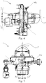
- FIGS. 1 and 2 show different perspective views of a first embodiment of an adjustment system 1 according to the invention for pivoting at least one optically relevant component 2 of a vehicle headlamp about a first and a second axis y and z.
- the adjustment system 1 comprises a first holding element 3 for holding the optically relevant component 2, a second holding element 4 for displaceably mounting the first Retaining element 3 on the second support member 4, a support frame 5 for slidably supporting the second support member 4 on the support frame 5, and a first holding member 3 acting on the first adjusting 6 for displacement of the first support member 3 with respect to the second support member 4. Further includes the adjustment system 1 has a second adjusting device 7 acting on the second retaining element 4 for displacing the second retaining element 4 with respect to the support frame 5, the first retaining element 3 and the second retaining element 4 having a first group of guide means 3a and 4a engaged with each other.
- the first group of guide means 3a, 4a guides a displacement of the first holding element 3 about the second holding element 4 along a circular arc KBy (see FIG Fig. 4 ) about the first axis y.
- the first axis is oriented horizontally and normal to the main travel direction x of a vehicle, wherein the main travel direction x with the first axis y spans a plane which is oriented normal to a vertically oriented second axis z.
- the first axis y could also be oriented vertically and the second axis z horizontally oriented.
- the second holding element 4 and the support frame 5 have a mutually engaging second group of guide means 4b and 5a, by means of which second group of guide means 4b, 5a, a displacement of the second support member 4 with respect to the support frame 5 along a circular arc KBz (see Fig. 5 ) is set around the second axis z.
- the first and the second axis y and z are oriented normal to each other.
- the arcs are designed in such a way that the respective axis coincides with the center of the respective arc.
- the first group of guide means 3a, 4a has at least one circular arc-shaped receiving portion 4a, which is delimited by a retaining nose 4a 'in such a way that a guide means 3a accommodated in the receiving portion 4a - which is for example in the form of a projection - exclusively in the assembled state the axis y can be pivoted and displacements in other directions are prevented as possible.
- FIG. 1 shows retaining tabs 4a 'a right side and FIG. 2 Holding lugs 4a 'a left side of the adjustment system 1 (seen from the front). Furthermore is in FIG.
- a rotary shaft 4c is mounted, which is oriented parallel to the first axis y and at least one toothed portion 4c ', wherein the first holding element 3rd a corresponding toothing 3c ', by means of which the first retaining element 3 is supported on the second retaining element 4.
- the toothing 3c 'of the first retaining element 3 is engaged with the toothed section 4c' in such a way that pivoting of the first retaining element 3 about the first axis y causes a rotational movement of the rotary shaft 4c.
- the rotary shaft 4c thus minimizes the play of movement of the first holding element 3 and ensures a particularly reliable guidance.
- a second group may also be provided on guide means.
- the second group of guide means 4b and 5a has at least one circular arc-shaped receiving portion 5a, in which at least one of the second group of guide means 4b and 5a also associated with corresponding guide projection 4b is added.
- the receiving portion 5a is associated with the support frame 5 and the guide projection 4b is associated with the second support member 4 (or vice versa).
- On the support frame 5 retaining lugs 5a 'are formed.
- a rotary shaft 5c is mounted on the support frame 5, which is oriented parallel to the second axis z and at least one toothed portion 5c ', wherein the second support member 4 has a corresponding toothing 4c ", by means of which the second support member 4 on the support frame The toothing 4c "of the second retaining element 4 is engaged with the toothed section 5c 'in such a way that a pivoting of the second retaining element 4 about the second axis z causes a rotational movement of the rotary shaft 5c. Similar to the rotation shaft 4c, the rotation shaft 5c causes the play of the slide mechanism to be minimized.
- the optically relevant component 2 comprises an imaging optical element, namely in the form of a projection lens.
- the projection lens has a main emission direction along an optical axis, the imaging optical element being pivotable about the first and second axes y and z such that the optical axis is orientable normal to the first and second axes y and z.
- the projection lens 2 has a vertex P, wherein the first and the second axis y and z intersect each other in the region of the vertex P.
- the first adjusting device 6 is adapted to be fixedly connected to a vehicle headlight housing, wherein the first Adjustment 6 has a pivoting arm 6a, which is pivotable about an axis by means of the first adjusting device 6, which is oriented parallel to the first axis y, wherein the pivoting arm 6a has a coupling portion 6d ', which is adapted to a corresponding coupling portion 3d' of first holding member 3 for pivoting the first holding member 3 about the first axis y intervene.
- the coupling sections 6d 'and 3d' are adapted to non-positively transmit a pivoting movement of the pivoting arm to the first retaining element 3, the coupling sections 6d 'and 3d' being displaceable relative to each other.
- FIGS. 8a and 8b The interaction of the coupling sections 6d 'and 3d' is in FIGS. 8a and 8b shown in more detail.
- the coupling portion 6d ' is formed as a ball head, which is received in a correspondingly shaped recess 3d', wherein the ball head can move within the recess such that on the one hand a pivoting movement of the arm 6a non-positively transmitted to the first retaining element 3
- the coupling portion 6d ' is formed as a ball head, which is received in a correspondingly shaped recess 3d', wherein the ball head can move within the recess such that on the one hand a pivoting movement of the arm 6a non-positively transmitted to the first retaining element 3
- the different pivot axes of pivoting arm 6a and first holding element 3 different path of movement can be compensated by the different pivot axes of pivoting arm 6a and first holding element 3 different path of movement.
- the second adjusting device 7 of the adjusting system 1 has a sliding arm 7a, which is displaceable in the direction of the first axis y by means of the second adjusting device 7, wherein the sliding arm 7a has a coupling section 7d ', which is adapted to a corresponding coupling section 4d 'of the second holding element 4 for pivoting the second holding element 4 about the second axis z, wherein the coupling portions 4d' and 7d 'are adapted to non-positively transfer a sliding movement of the sliding arm 7a on the second holding element 4.
- the coupling portion 7d ' is designed as a ball head, which engages in a corresponding cylindrical receiving opening 4d', wherein the longitudinal axis of the cylindrical receiving opening is oriented normal to the first axis y.
- a longitudinal displacement of the sliding arm 7a can be achieved in the present embodiment by rotation about its longitudinal axis, since the sliding arm 7a has a threaded portion 7e, which engages a threaded portion 5e of the fixed support frame 5 (see Fig. 6 ).
- the Adjusting devices 6 and 7 will not be discussed in more detail below, since such are well known from the prior art and in the present case only have to be set up to move the sliding arm 7a or to pivot the pivot arm 6a.
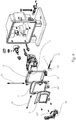
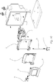
- FIGS. 3 to 5 show different views of the adjustment system 1, wherein only a few reference numbers have been entered for clarity.
- the exemplary vertical adjustment range comprises an angle of +/- 7.5 ° from a zero position.
- the exemplary lateral adjustment range is an angle of +/- 3.5 ° starting from a zero position.
- FIG. 7 shows a detailed perspective view of the already described horizontal pivot mechanism of the adjustment system.
- FIGS. 9a to 9g show individual steps of mounting the adjustment system according to Fig. 1 to 8b , wherein no reference numerals are shown for clarity.
- FIG. 10 shows an alternative embodiment of an adjustment system according to the invention 1.
- the adjusting devices 6 and 7 are designed differently, namely as servomotors whose axis of rotation acts directly on the rotary shaft 4c and 5c.
- the invention can be used for a large number of different light functions.
- cornering light low beam, high beam, laser scanner, LED matrix light, etc. may be mentioned here.
Landscapes
- Engineering & Computer Science (AREA)
- Mechanical Engineering (AREA)
- Lighting Device Outwards From Vehicle And Optical Signal (AREA)
- Non-Portable Lighting Devices Or Systems Thereof (AREA)
Priority Applications (7)
| Application Number | Priority Date | Filing Date | Title |
|---|---|---|---|
| EP18151125.4A EP3511204A1 (fr) | 2018-01-11 | 2018-01-11 | Système de réglage permettant le pivotement d'au moins un composant optique d'un phare de véhicule autour d'un premier et d'un second axes |
| JP2020529749A JP6986157B2 (ja) | 2018-01-11 | 2018-12-17 | 第1及び第2の軸線周りに車両投光器の少なくとも1つの光学関連構成部材を旋回させるための調整システム |
| CN201880086236.8A CN111565974B (zh) | 2018-01-11 | 2018-12-17 | 用于使至少一个与光学有关的构件摆动的调整系统 |
| PCT/EP2018/085104 WO2019137736A1 (fr) | 2018-01-11 | 2018-12-17 | Système de réglage permettant de faire pivoter au moins un composant optiquement pertinent d'un phare de véhicule sur un premier et un deuxieme axe |
| EP18826269.5A EP3737585B1 (fr) | 2018-01-11 | 2018-12-17 | Disposif d'éclairage d'un phare de véhicule avec au moins un composant optique et un système de réglage permettant de faire pivoter le composant optique autour d'un premier axe et d'un deuxieme axe |
| KR1020207004500A KR102300342B1 (ko) | 2018-01-11 | 2018-12-17 | 제1 및 제2 축을 중심으로 차량 헤드램프의 적어도 하나의 광학 관련 부품을 회동시키기 위한 조정 시스템 |
| US16/767,719 US11420550B2 (en) | 2018-01-11 | 2018-12-17 | Adjusting system for pivoting at least one optically relevant component of a vehicle headlight about a first and a second axis |
Applications Claiming Priority (1)
| Application Number | Priority Date | Filing Date | Title |
|---|---|---|---|
| EP18151125.4A EP3511204A1 (fr) | 2018-01-11 | 2018-01-11 | Système de réglage permettant le pivotement d'au moins un composant optique d'un phare de véhicule autour d'un premier et d'un second axes |
Publications (1)
| Publication Number | Publication Date |
|---|---|
| EP3511204A1 true EP3511204A1 (fr) | 2019-07-17 |
Family
ID=60954922
Family Applications (2)
| Application Number | Title | Priority Date | Filing Date |
|---|---|---|---|
| EP18151125.4A Withdrawn EP3511204A1 (fr) | 2018-01-11 | 2018-01-11 | Système de réglage permettant le pivotement d'au moins un composant optique d'un phare de véhicule autour d'un premier et d'un second axes |
| EP18826269.5A Active EP3737585B1 (fr) | 2018-01-11 | 2018-12-17 | Disposif d'éclairage d'un phare de véhicule avec au moins un composant optique et un système de réglage permettant de faire pivoter le composant optique autour d'un premier axe et d'un deuxieme axe |
Family Applications After (1)
| Application Number | Title | Priority Date | Filing Date |
|---|---|---|---|
| EP18826269.5A Active EP3737585B1 (fr) | 2018-01-11 | 2018-12-17 | Disposif d'éclairage d'un phare de véhicule avec au moins un composant optique et un système de réglage permettant de faire pivoter le composant optique autour d'un premier axe et d'un deuxieme axe |
Country Status (6)
| Country | Link |
|---|---|
| US (1) | US11420550B2 (fr) |
| EP (2) | EP3511204A1 (fr) |
| JP (1) | JP6986157B2 (fr) |
| KR (1) | KR102300342B1 (fr) |
| CN (1) | CN111565974B (fr) |
| WO (1) | WO2019137736A1 (fr) |
Cited By (2)
| Publication number | Priority date | Publication date | Assignee | Title |
|---|---|---|---|---|
| EP3855131A1 (fr) * | 2020-01-22 | 2021-07-28 | ZKW Group GmbH | Dispositif de réglage permettant de pivoter au moins un composant pertinent pour un phare de véhicule automobile |
| WO2026075957A1 (fr) * | 2024-10-04 | 2026-04-09 | Valeo Vision | Module lumineux pivotant pour système d'éclairage de véhicule |
Families Citing this family (3)
| Publication number | Priority date | Publication date | Assignee | Title |
|---|---|---|---|---|
| TWI785943B (zh) * | 2021-12-22 | 2022-12-01 | 大億交通工業製造股份有限公司 | 車燈之水平光形調整系統 |
| FR3131620B1 (fr) * | 2021-12-30 | 2023-12-15 | Valeo Vision Belgique | Dispositif de reglage de l’inclinaison du faisceau lumineux emis par un projecteur |
| CN114987326B (zh) * | 2022-04-21 | 2025-09-19 | 东风汽车集团股份有限公司 | 一种车灯调节系统 |
Citations (5)
| Publication number | Priority date | Publication date | Assignee | Title |
|---|---|---|---|---|
| US20110063866A1 (en) * | 2009-09-14 | 2011-03-17 | Koito Manufacturing Co., Ltd. | Vehicle headlamp |
| EP2724888A2 (fr) * | 2012-10-24 | 2014-04-30 | Koito Manufacturing Co., Ltd. | Phare de véhicule |
| AT513918B1 (de) | 2013-02-01 | 2014-11-15 | Zizala Lichtsysteme Gmbh | Einstellsystem für einen Fahrzeug-Scheinwerfer sowie Fahrzeug-Scheinwerfer |
| US20150009699A1 (en) * | 2013-07-05 | 2015-01-08 | Koito Manufacturing Co., Ltd. | Vehicular headlamp |
| EP3048360A1 (fr) * | 2013-08-23 | 2016-07-27 | Koito Manufacturing Co., Ltd. | Dispositif de lampe pour véhicule et dispositif d'éclairage pour véhicule |
Family Cites Families (8)
| Publication number | Priority date | Publication date | Assignee | Title |
|---|---|---|---|---|
| US5868488A (en) * | 1996-11-18 | 1999-02-09 | Speak; Justin R. | Adjustable headlights, headlight adjusting and direction sensing control system and method of adjusting headlights |
| US6478457B1 (en) * | 2000-09-15 | 2002-11-12 | Richard W. Manley | Movable vehicle headlight system |
| US8577556B1 (en) * | 2010-12-02 | 2013-11-05 | II Phares Azarael Noel | Electronically controlled gimbaled platform for steadying illumination sources on vehicles |
| US9010973B2 (en) * | 2012-04-05 | 2015-04-21 | Tricore Corporation | Motor vehicle headlight positioning device |
| JP6178559B2 (ja) | 2012-10-24 | 2017-08-09 | 株式会社小糸製作所 | 車輌用前照灯 |
| JP2015015186A (ja) * | 2013-07-05 | 2015-01-22 | 株式会社小糸製作所 | 車輌用前照灯 |
| JP6159631B2 (ja) * | 2013-09-26 | 2017-07-05 | 株式会社小糸製作所 | 車両用灯具 |
| US10081293B2 (en) * | 2015-11-05 | 2018-09-25 | Ford Global Technologies, Llc | Headlight beam adjustment system and related method |
-
2018
- 2018-01-11 EP EP18151125.4A patent/EP3511204A1/fr not_active Withdrawn
- 2018-12-17 CN CN201880086236.8A patent/CN111565974B/zh active Active
- 2018-12-17 US US16/767,719 patent/US11420550B2/en active Active
- 2018-12-17 KR KR1020207004500A patent/KR102300342B1/ko active Active
- 2018-12-17 JP JP2020529749A patent/JP6986157B2/ja active Active
- 2018-12-17 EP EP18826269.5A patent/EP3737585B1/fr active Active
- 2018-12-17 WO PCT/EP2018/085104 patent/WO2019137736A1/fr not_active Ceased
Patent Citations (5)
| Publication number | Priority date | Publication date | Assignee | Title |
|---|---|---|---|---|
| US20110063866A1 (en) * | 2009-09-14 | 2011-03-17 | Koito Manufacturing Co., Ltd. | Vehicle headlamp |
| EP2724888A2 (fr) * | 2012-10-24 | 2014-04-30 | Koito Manufacturing Co., Ltd. | Phare de véhicule |
| AT513918B1 (de) | 2013-02-01 | 2014-11-15 | Zizala Lichtsysteme Gmbh | Einstellsystem für einen Fahrzeug-Scheinwerfer sowie Fahrzeug-Scheinwerfer |
| US20150009699A1 (en) * | 2013-07-05 | 2015-01-08 | Koito Manufacturing Co., Ltd. | Vehicular headlamp |
| EP3048360A1 (fr) * | 2013-08-23 | 2016-07-27 | Koito Manufacturing Co., Ltd. | Dispositif de lampe pour véhicule et dispositif d'éclairage pour véhicule |
Cited By (6)
| Publication number | Priority date | Publication date | Assignee | Title |
|---|---|---|---|---|
| EP3855131A1 (fr) * | 2020-01-22 | 2021-07-28 | ZKW Group GmbH | Dispositif de réglage permettant de pivoter au moins un composant pertinent pour un phare de véhicule automobile |
| WO2021148214A1 (fr) * | 2020-01-22 | 2021-07-29 | Zkw Group Gmbh | Dispositif de positionnement pour faire pivoter au moins un composant concerné pour un projecteur de véhicule automobile |
| CN115023590A (zh) * | 2020-01-22 | 2022-09-06 | Zkw集团有限责任公司 | 用于使机动车前照灯的至少一个相关构件枢转的设定装置 |
| JP2023510569A (ja) * | 2020-01-22 | 2023-03-14 | ツェットカーヴェー グループ ゲーエムベーハー | 自動車投光器用の少なくとも1つの関連部材を旋回させるための調節装置 |
| JP7292521B2 (ja) | 2020-01-22 | 2023-06-16 | ツェットカーヴェー グループ ゲーエムベーハー | 自動車投光器用の少なくとも1つの関連部材を旋回させるための調節装置 |
| WO2026075957A1 (fr) * | 2024-10-04 | 2026-04-09 | Valeo Vision | Module lumineux pivotant pour système d'éclairage de véhicule |
Also Published As
| Publication number | Publication date |
|---|---|
| JP2021504235A (ja) | 2021-02-15 |
| US11420550B2 (en) | 2022-08-23 |
| KR102300342B1 (ko) | 2021-09-10 |
| WO2019137736A1 (fr) | 2019-07-18 |
| JP6986157B2 (ja) | 2021-12-22 |
| EP3737585B1 (fr) | 2021-09-15 |
| US20200384910A1 (en) | 2020-12-10 |
| CN111565974B (zh) | 2023-11-24 |
| CN111565974A (zh) | 2020-08-21 |
| EP3737585A1 (fr) | 2020-11-18 |
| KR20200032717A (ko) | 2020-03-26 |
Similar Documents
| Publication | Publication Date | Title |
|---|---|---|
| EP3737585B1 (fr) | Disposif d'éclairage d'un phare de véhicule avec au moins un composant optique et un système de réglage permettant de faire pivoter le composant optique autour d'un premier axe et d'un deuxieme axe | |
| AT514402B1 (de) | Fahrzeugscheinwerfer | |
| EP2719579B1 (fr) | Phare pour un véhicule automobile | |
| AT516100B1 (de) | Einstellsystem für einen Fahrzeugscheinwerfer sowie Fahrzeugscheinwerfer | |
| EP3616993B1 (fr) | Phare de véhicule automobile avec dispositif de réglage | |
| EP2762358B1 (fr) | Système de réglage de phare de véhicule | |
| EP3310616B1 (fr) | Phare de véhicule avec des modules optiques ajustables | |
| EP3505396B1 (fr) | Zone de pivotement centrale | |
| EP3069931A2 (fr) | Système de réglage de phare de véhicule | |
| EP0055209B1 (fr) | Dispositif pour faire tourner des faisceaux lumineux | |
| DE102014007865B4 (de) | Fahrzeugscheinwerfer | |
| EP2886394B1 (fr) | Dispositif d'éclairage pour un phare de véhicule automobile | |
| EP4094049B1 (fr) | Dispositif de réglage permettant de pivoter au moins un composant pertinent pour un phare de véhicule automobile | |
| DE102018122676A1 (de) | Scheinwerfer für Kraftfahrzeuge | |
| DE102013106562B4 (de) | Verstelleinrichtung für einen Kraftfahrzeugscheinwerfer | |
| EP3317581A1 (fr) | Dispositif d'éclairage pour un projecteur de véhicule automobile | |
| EP3699028A1 (fr) | Dispositif d'éclairage pour un phare de véhicule automobile | |
| AT506090B1 (de) | Verstellbare lampenhalterung | |
| DE102009051026A1 (de) | LED-Beleuchtungsvorrichtung umfassend wenigstens eine LED und eine Platine, auf der die LED angeordnet ist, und Kraftfahrzeug | |
| EP0425476A2 (fr) | Dispositif pour un déplacement relatif | |
| EP3851739B1 (fr) | Systeme d'optique d'éclairage et éclairage pourvu de systeme d'optique d'éclairage | |
| AT514129B1 (de) | Fahrzeugscheinwerfer | |
| EP2469162B1 (fr) | Dispositif de support pour une lampe | |
| EP3599131A1 (fr) | Phare pour un véhicule automobile |
Legal Events
| Date | Code | Title | Description |
|---|---|---|---|
| PUAI | Public reference made under article 153(3) epc to a published international application that has entered the european phase |
Free format text: ORIGINAL CODE: 0009012 |
|
| AK | Designated contracting states |
Kind code of ref document: A1 Designated state(s): AL AT BE BG CH CY CZ DE DK EE ES FI FR GB GR HR HU IE IS IT LI LT LU LV MC MK MT NL NO PL PT RO RS SE SI SK SM TR |
|
| AX | Request for extension of the european patent |
Extension state: BA ME |
|
| STAA | Information on the status of an ep patent application or granted ep patent |
Free format text: STATUS: THE APPLICATION IS DEEMED TO BE WITHDRAWN |
|
| 18D | Application deemed to be withdrawn |
Effective date: 20200118 |