EP3737585B1 - Disposif d'éclairage d'un phare de véhicule avec au moins un composant optique et un système de réglage permettant de faire pivoter le composant optique autour d'un premier axe et d'un deuxieme axe - Google Patents
Disposif d'éclairage d'un phare de véhicule avec au moins un composant optique et un système de réglage permettant de faire pivoter le composant optique autour d'un premier axe et d'un deuxieme axe Download PDFInfo
- Publication number
- EP3737585B1 EP3737585B1 EP18826269.5A EP18826269A EP3737585B1 EP 3737585 B1 EP3737585 B1 EP 3737585B1 EP 18826269 A EP18826269 A EP 18826269A EP 3737585 B1 EP3737585 B1 EP 3737585B1
- Authority
- EP
- European Patent Office
- Prior art keywords
- holding element
- axis
- lighting device
- holding
- pivoting
- Prior art date
- Legal status (The legal status is an assumption and is not a legal conclusion. Google has not performed a legal analysis and makes no representation as to the accuracy of the status listed.)
- Active
Links
Images


Classifications
-
- B—PERFORMING OPERATIONS; TRANSPORTING
- B60—VEHICLES IN GENERAL
- B60Q—ARRANGEMENT OF SIGNALLING OR LIGHTING DEVICES, THE MOUNTING OR SUPPORTING THEREOF OR CIRCUITS THEREFOR, FOR VEHICLES IN GENERAL
- B60Q1/00—Arrangement of optical signalling or lighting devices, the mounting or supporting thereof or circuits therefor
- B60Q1/02—Arrangement of optical signalling or lighting devices, the mounting or supporting thereof or circuits therefor the devices being primarily intended to illuminate the way ahead or to illuminate other areas of way or environments
- B60Q1/04—Arrangement of optical signalling or lighting devices, the mounting or supporting thereof or circuits therefor the devices being primarily intended to illuminate the way ahead or to illuminate other areas of way or environments the devices being headlights
- B60Q1/06—Arrangement of optical signalling or lighting devices, the mounting or supporting thereof or circuits therefor the devices being primarily intended to illuminate the way ahead or to illuminate other areas of way or environments the devices being headlights adjustable, e.g. remotely-controlled from inside vehicle
- B60Q1/076—Arrangement of optical signalling or lighting devices, the mounting or supporting thereof or circuits therefor the devices being primarily intended to illuminate the way ahead or to illuminate other areas of way or environments the devices being headlights adjustable, e.g. remotely-controlled from inside vehicle by electrical means including means to transmit the movements, e.g. shafts or joints
-
- B—PERFORMING OPERATIONS; TRANSPORTING
- B60—VEHICLES IN GENERAL
- B60Q—ARRANGEMENT OF SIGNALLING OR LIGHTING DEVICES, THE MOUNTING OR SUPPORTING THEREOF OR CIRCUITS THEREFOR, FOR VEHICLES IN GENERAL
- B60Q1/00—Arrangement of optical signalling or lighting devices, the mounting or supporting thereof or circuits therefor
- B60Q1/02—Arrangement of optical signalling or lighting devices, the mounting or supporting thereof or circuits therefor the devices being primarily intended to illuminate the way ahead or to illuminate other areas of way or environments
- B60Q1/04—Arrangement of optical signalling or lighting devices, the mounting or supporting thereof or circuits therefor the devices being primarily intended to illuminate the way ahead or to illuminate other areas of way or environments the devices being headlights
- B60Q1/06—Arrangement of optical signalling or lighting devices, the mounting or supporting thereof or circuits therefor the devices being primarily intended to illuminate the way ahead or to illuminate other areas of way or environments the devices being headlights adjustable, e.g. remotely-controlled from inside vehicle
- B60Q1/068—Arrangement of optical signalling or lighting devices, the mounting or supporting thereof or circuits therefor the devices being primarily intended to illuminate the way ahead or to illuminate other areas of way or environments the devices being headlights adjustable, e.g. remotely-controlled from inside vehicle by mechanical means
- B60Q1/0683—Adjustable by rotation of a screw
-
- B—PERFORMING OPERATIONS; TRANSPORTING
- B60—VEHICLES IN GENERAL
- B60Q—ARRANGEMENT OF SIGNALLING OR LIGHTING DEVICES, THE MOUNTING OR SUPPORTING THEREOF OR CIRCUITS THEREFOR, FOR VEHICLES IN GENERAL
- B60Q1/00—Arrangement of optical signalling or lighting devices, the mounting or supporting thereof or circuits therefor
- B60Q1/02—Arrangement of optical signalling or lighting devices, the mounting or supporting thereof or circuits therefor the devices being primarily intended to illuminate the way ahead or to illuminate other areas of way or environments
- B60Q1/04—Arrangement of optical signalling or lighting devices, the mounting or supporting thereof or circuits therefor the devices being primarily intended to illuminate the way ahead or to illuminate other areas of way or environments the devices being headlights
- B60Q1/06—Arrangement of optical signalling or lighting devices, the mounting or supporting thereof or circuits therefor the devices being primarily intended to illuminate the way ahead or to illuminate other areas of way or environments the devices being headlights adjustable, e.g. remotely-controlled from inside vehicle
- B60Q1/08—Arrangement of optical signalling or lighting devices, the mounting or supporting thereof or circuits therefor the devices being primarily intended to illuminate the way ahead or to illuminate other areas of way or environments the devices being headlights adjustable, e.g. remotely-controlled from inside vehicle automatically
- B60Q1/12—Arrangement of optical signalling or lighting devices, the mounting or supporting thereof or circuits therefor the devices being primarily intended to illuminate the way ahead or to illuminate other areas of way or environments the devices being headlights adjustable, e.g. remotely-controlled from inside vehicle automatically due to steering position
Definitions
- the invention relates to a lighting device for a vehicle headlight with at least one optically relevant component and an adjustment system for pivoting the optically relevant component about a first and a second axis.
- the invention further relates to a vehicle headlight, in particular a motor vehicle headlight, with a lighting device according to the invention.
- Adjustment systems are known from the prior art and are frequently used in vehicle headlight applications in order to adjust the vertical deflection (for example headlight range adjustment) or the horizontal deflection (basic setting or for example cornering lights) of a light distribution.
- Adjustment systems should on the one hand enable a reliable adjustment of an optically relevant component, on the other hand the space requirement of such adjustment systems should be minimized in order to restrict the design of a vehicle headlight as little as possible.
- Previous setting systems mostly have an adjustment triangle with a fixed bearing point and two points of application, whereby an axis is formed by the connection of the fixed bearing point and the point of application, and a pivoting movement is generated by moving the points of application.
- Such adjustment systems require a certain amount of space due to the design of the pivoting triangle.
- a lighting device with a different type of adjustment system is off EP 2 724 888 A2 or US 2011/0063866 A1 known.
- the adjustment system according to the invention allows adjustment along a spherical circular arc.
- the circular arcs are selected in such a way that the associated axes of rotation lie at the apex of the optically relevant component in an area arranged in the light emission direction after the optically relevant component.
- the first axis is oriented horizontally and the second axis is oriented vertically.
- the information regarding the orientation relate to the built-in state of the adjustment system. Via the horizontal axis, for example, the Headlight range of a vehicle headlight can be regulated.
- the light image of a vehicle headlight can be swiveled sideways by means of the vertical axis.
- first axis is oriented vertically and the second axis is oriented horizontally.
- an imaging optical element is regarded as an optically relevant component.
- an imaging optical element is understood to mean any optical element by means of which a light distribution is finally formed.
- a lens in particular a projection lens, is provided for the final shaping of light.
- the adjustment system can advantageously be designed in such a way that the imaging optical element has a main emission direction which, in a central position, is oriented normal to the first and second axes.
- the imaging optical element has a main emission direction along an optical axis, the imaging optical element being pivotable about the first and second axes in such a way that the optical axis can be oriented normally to the first and second axes.
- the imaging optical element in the form of a lens in particular a projection lens, has an apex, the first and second axes intersecting one another in the region of the apex.
- a pivoting movement takes place exclusively around the vertex of the imaging optical element. In this case, a pivoting movement only changes the orientation of the vertex, but not its position.
- this property is particularly advantageous because the vertex remains positionally stable during a pivoting movement and thus the space requirement of the imaging optical element is minimal despite pivotability.
- the vertex lies in the direction of the optical axis of the imaging optical element at its vertex, the term "in the region" means that efforts are made to make the intersection of the axes essentially coincide with the vertex, but with deviations of a few millimeters can enter.
- the first group of guide means has at least one circular-arc-shaped receiving section in which at least one corresponding guide projection, which is also assigned to the first group of guide means, is received, the receiving section being assigned to the second holding element and the guide projection being assigned to the first holding element or vice versa.
- a rotary shaft is mounted on the second holding element, which is oriented parallel to the first axis and has at least one toothed section, wherein the first holding element has a corresponding toothing, by means of which the first holding element is supported on the second holding element, wherein the toothing of the first holding element is in engagement with the toothed section in such a way that pivoting of the first holding element about the first axis causes a rotary movement of the rotary shaft.
- the rotating shaft thus supports the first holding element and prevents play in the movement of the associated pivoting device.
- the second group of guide means has at least one arc-shaped receiving section in which at least one corresponding guide projection, which is also assigned to the second group of guide means, is received, the receiving section being the support frame is assigned and the guide projection is assigned to the second holding element or vice versa.
- a rotary shaft is mounted on the support frame, which is oriented parallel to the second axis and has at least one toothed section, wherein the second holding element has a corresponding toothing, by means of which the second holding element is supported on the support frame, the Toothing of the second holding element is in engagement with the toothed section in such a way that pivoting of the second holding element about the second axis causes a rotary movement of the rotary shaft.
- the rotary shaft thus supports the second holding element and prevents play in the movement of the associated pivoting device.
- the guide track being designed as a circular arc, the center of which forms the axis of rotation, the axis of rotation being oriented horizontally and intersecting the apex of the projection lens.
- the first adjustment device is set up to be fixedly connected to a vehicle headlight housing, the first adjustment device having a pivot arm that can be pivoted by means of the first adjustment device about an axis that is oriented parallel to the first axis , wherein the pivot arm has a coupling section which is set up to engage in a corresponding coupling section of the first holding element for pivoting the first holding element about the first axis, wherein the coupling sections are set up to transmit a swiveling movement of the swivel arm to the first holding element in a non-positive manner, wherein the coupling sections are displaceable relative to one another.
- the coupling sections can be designed to be displaceable in the direction of the first axis and transversely thereto.
- the second adjustment device is set up to be fixedly connected to a vehicle headlamp housing, the second adjustment device having a sliding arm which can be moved in the direction of the first axis by means of the second adjusting device, the sliding arm having a coupling section which is set up to engage in a corresponding coupling section of the second holding element for pivoting the second holding element about the second axis, the coupling sections being set up to transmit a sliding movement of the sliding arm to the second holding element in a non-positive manner.
- the adjustment of the optically relevant component by means of the first adjustment device takes place independently of an adjustment by means of the second adjustment device.
- the lighting device can furthermore contain at least one light source or also a plurality of light sources, wherein, for example, LED light sources, halogen light sources and / or laser light sources can be provided.
- the invention also relates to a vehicle headlight, in particular a motor vehicle headlight, with a lighting device according to the invention.
- the invention also relates to a vehicle, in particular a motor vehicle, with at least one vehicle headlight according to the invention.
- the lighting device according to the invention can be used to set a large number of different light distributions and light systems.
- such an adjustment system can be used for cornering lights, low beams, high beams, laser scanners, LED matrix headlights, etc.
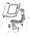
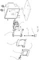
- Figures 1 and 2 show different perspective representations of a first embodiment of an adjustment system 1 according to the invention for pivoting at least one optically relevant component 2 of a vehicle headlight about a first and a second axis y and z.
- the adjustment system 1 comprises a first holding element 3 for holding the optically relevant component 2, a second holding element 4 for the displaceable holding of the first
- the adjustment system 1 has a second adjustment device 7 engaging the second holding element 4 for displacing the second holding element 4 with respect to the support frame 5, the first holding element 3 and the second holding element 4 having an interengaging first group of guide means 3a and 4a.
- the first group of guide means 3a, 4a shifts the first holding element 3 around the second holding element 4 along a circular arc KBy (see FIG Fig. 4 ) about the first axis y.
- the first axis is oriented horizontally and normal to the main direction of travel x of a vehicle, the main direction of travel x spanning a plane with the first axis y that is oriented normal to a vertically oriented second axis z.
- the first axis y could also be oriented vertically and the second axis z horizontally.
- the second holding element 4 and the support frame 5 have an interengaging second group of guide means 4b and 5a, by means of which the second group of guide means 4b, 5a allows the second holding element 4 to be displaced in relation to the support frame 5 along a circular arc KBz (see FIG Fig. 5 ) is set around the second axis z.
- the first and second axes y and z are oriented normal to one another.
- the arcs are designed in such a way that the respective axis coincides with the center point of the respective arc.
- the first group of guide means 3a, 4a has at least one circular-arc-shaped receiving section 4a, which is limited by a retaining lug 4a 'in such a way that a guide means 3a received in the receiving section 4a - which is, for example, in the form of a projection - exclusively in the assembled state the axis y can be pivoted and shifts in other directions are prevented as far as possible.
- four retaining lugs 4a ′ are provided in the present embodiment, which are formed on opposite sides of the second retaining means 4.
- Figure 1 shows retaining lugs 4a 'of a right side and Figure 2 Holding lugs 4a 'of a left side of the adjustment system 1 (seen from the front).
- a rotary shaft 4c is mounted on the second holding element 4, which is oriented parallel to the first axis y and has at least one toothed section 4c ′, the first holding element 3 a corresponding toothing 3c ′, by means of which the first holding element 3 is supported on the second holding element 4.
- the toothing 3c 'of the first holding element 3 is in engagement with the toothed section 4c' in such a way that pivoting the first holding element 3 about the first axis y causes a rotary movement of the rotary shaft 4c.
- the rotary shaft 4c thus minimizes the movement play of the first holding element 3 and ensures particularly reliable guidance.
- a second group of guide means can also be provided.
- the second group of guide means 4b and 5a has at least one circular-arc-shaped receiving section 5a in which at least one corresponding guide projection 4b, which is also assigned to the second group of guide means 4b and 5a, is received.
- the receiving section 5a is assigned to the support frame 5 and the guide projection 4b is assigned to the second holding element 4 (or vice versa). Retaining lugs 5a 'are formed on the support frame 5.
- a rotary shaft 5c is mounted on the support frame 5, which is oriented parallel to the second axis z and has at least one toothed section 5c ', the second holding element 4 having corresponding teeth 4c ′′, by means of which the second holding element 4 on the support frame 5
- the toothing 4c ′′ of the second holding element 4 is in engagement with the toothed section 5c ′ in such a way that pivoting the second holding element 4 about the second axis z causes a rotary movement of the rotary shaft 5c.
- the rotary shaft 5c Analogously to the rotary shaft 4c, the rotary shaft 5c has the effect that the play of the displacement mechanism is minimized.
- the optically relevant component 2 comprises an imaging optical element in the form of a lens, namely in the form of a projection lens.
- the projection lens has a main emission direction along an optical axis, the optical imaging element being pivotable about the first and second axes y and z in such a way that the optical axis can be oriented normally to the first and second axes y and z. In other words, this means that the circular arcs 4a and 5a or the entire adjusting mechanism are designed accordingly.
- the projection lens 2 has an apex P, the first and second axes y and z intersecting one another in the region of the apex P.
- the first adjusting device 6 is set up to be fixedly connected to a vehicle headlight housing, the first Adjusting device 6 has a pivot arm 6a which can be pivoted by means of the first adjustment device 6 about an axis which is oriented parallel to the first axis y, the pivot arm 6a having a coupling section 6d 'which is set up to be connected to a corresponding coupling section 3d' of the first holding element 3 for pivoting the first holding element 3 to engage around the first axis y.
- the coupling sections 6d 'and 3d' are set up to transmit a pivoting movement of the pivoting arm to the first holding element 3 in a non-positive manner, the coupling sections 6d 'and 3d' being displaceable relative to one another.
- FIG Figures 8a and 8b The interaction of the coupling sections 6d 'and 3d' is shown in FIG Figures 8a and 8b shown in more detail.
- the coupling section 6d ' is designed as a spherical head which is received in a correspondingly shaped recess 3d', the spherical head being able to be displaced within the recess in such a way that, on the one hand, a pivoting movement of the arm 6a is non-positively transmitted to the first holding element 3 on the other hand, a path of movement which deviates from the different pivot axes of pivot arm 6a and first holding element 3 can be compensated for.
- a displacement in the direction of the y-axis is also possible, which is effected as a result of the second holding element 4 pivoting about the second axis z, since the first holding element 3 is moved together with the second holding element 4.
- the second adjustment device 7 of the adjustment system 1 has a sliding arm 7a which can be displaced in the direction of the first axis y by means of the second adjusting device 7, the sliding arm 7a having a coupling section 7d 'which is designed to be inserted into a corresponding coupling section 4d 'of the second holding element 4 to pivot the second holding element 4 about the second axis z, the coupling sections 4d' and 7d 'being set up to transmit a sliding movement of the sliding arm 7a to the second holding element 4 in a non-positive manner.
- the coupling section 7d ' is designed as a spherical head which engages in a corresponding cylindrical receiving opening 4d', the longitudinal axis of the cylindrical receiving opening being oriented normal to the first axis y.
- a longitudinal displacement of the sliding arm 7a can be achieved in the present exemplary embodiment by rotating it about its longitudinal axis, since the sliding arm 7a has a threaded section 7e which engages a threaded section 5e of the fixed support frame 5 (see FIG Fig. 6 ).
- the Adjusting devices 6 and 7 are not discussed in more detail below, since they are sufficiently known from the prior art and in the present case only need to be set up to move the sliding arm 7a or to pivot the swivel arm 6a.
- the Figures 3 to 5 show different views of the setting system 1, only isolated reference symbols having been entered for a better overview.
- the exemplary vertical adjustment range comprises an angle of +/- 7.5 ° starting from a zero position.
- the exemplary lateral adjustment range is an angle of +/- 3.5 ° starting from a zero position.
- Figure 7 shows a perspective detailed illustration of the horizontal pivoting mechanism of the adjustment system 1 already described.
- Figures 9a to 9g show the individual steps of assembling the adjustment system according to Figures 1 to 8b , no reference numerals are shown therein for a better overview.
- Figure 10 shows an alternative embodiment of an adjustment system 1 according to the invention.
- the adjusting devices 6 and 7 are designed differently, namely as servomotors,
- the invention can be used for a large number of different light functions. Examples are cornering lights, low beams, high beams, laser scanners, LED matrix lights, etc.
Landscapes
- Engineering & Computer Science (AREA)
- Mechanical Engineering (AREA)
- Lighting Device Outwards From Vehicle And Optical Signal (AREA)
- Non-Portable Lighting Devices Or Systems Thereof (AREA)
Claims (11)
- Dispositif d'éclairage pour un phare de véhicule comprenant : au moins un composant optiquement pertinent (2), un système de réglage (1) pour faire pivoter le composant optiquement pertinent (2) autour d'un premier et d'un second axe (y, z),- un premier élément de maintien (3) pour maintenir le composant optiquement pertinent (2),- un second élément de maintien (4) pour maintenir de manière déplaçable le premier élément de maintien (3) sur le second élément de maintien (4),- un cadre de support (5) pour maintenir de manière déplaçable le deuxième élément de maintien (4) sur le cadre de support (5), ainsi que- un premier dispositif de réglage (6) s'engageant sur le premier élément de maintien (3) pour déplacer le premier élément de maintien (3) par rapport au second élément de maintien (4), et- un second dispositif de réglage (7) s'engageant dans le second élément de de maintien (4) pour déplacer le second élément de de maintien (4) par rapport au cadre de support (5),dans lequel le premier élément de de maintien (3) et le second élément de de maintien (4) comprennent un premier groupe de moyens de guidage (3a, 4a) s'engageant mutuellement, premier groupe de moyens de guidage (3a, 4a) au moyen duquel un déplacement du premier élément de de maintien (3) autour du second élément de de maintien (4) est guidé le long d'un arc (KBy) autour du premier axe (y), etdans lequel le deuxième élément de de maintien (4) et le cadre de support (5) comprennent un deuxième groupe de moyens de guidage (4b, 5a) s'engageant mutuellement, au moyen duquel deuxième groupe de moyens de guidage (4b, 5a) un déplacement du deuxième élément de de maintien (4) par rapport au cadre de support (5) est guidé le long d'un arc (KBz) autour du deuxième axe (z),les premier et deuxième axes (y, z) étant orientés perpendiculairement l'un à l'autre, le composant optiquement pertinent (2) comprenant un élément optique de formation d'image sous la forme d'une lentille, en particulier une lentille de projection, qui présente un sommet (P), caractérisé en ce queles premier et deuxième axes (y, z) se coupent l'un l'autre dans la région du sommet (P).
- Dispositif d'éclairage selon la revendication 1, dans lequel le premier axe (y) est orienté horizontalement et le deuxième axe (z) est orienté verticalement.
- Dispositif d'éclairage selon la revendication 1, dans lequel le premier axe est orienté verticalement et le deuxième axe est orienté horizontalement.
- Dispositif d'éclairage selon l'une quelconque des revendications précédentes, dans lequel ledit élément optique d'imagerie a une direction de rayonnement principale le long d'un axe optique, ledit élément optique d'imagerie pouvant pivoter autour desdits premier et deuxième axes (y, z) de telle sorte que ledit axe optique puisse être orienté normalement auxdits premier et deuxième axes (y, z).
- Dispositif d'éclairage selon l'une quelconque des revendications précédentes, dans lequel ledit premier groupe de moyens de guidage (3a, 4a) comprend au moins une partie de réception en forme d'arc de cercle (4a) dans laquelle est reçue au moins une saillie de guidage correspondante (3a) également associée audit premier groupe de moyens de guidage (3a, 4a), ladite partie de réception (4a) étant associée audit deuxième élément de support (4) et ladite saillie de guidage (3a) étant associée audit premier élément de support (3) ou vice versa.
- Dispositif d'éclairage selon la revendication 5, dans lequel un arbre rotatif (4c) est monté sur le deuxième élément de retenue (4), lequel arbre rotatif est orienté parallèlement au premier axe (y) et présente au moins une partie dentée (4c'), le premier élément de retenue (3) présentant une denture correspondante (3c'), au moyen duquel le premier élément de retenue (3) s'appuie sur le deuxième élément de retenue (4), la denture (3c') du premier élément de retenue (3) étant en prise avec la partie dentée (4c') de telle sorte qu'un pivotement du premier élément de retenue (3) autour du premier axe (y) provoque un mouvement de rotation de l'arbre rotatif (4c).
- Dispositif d'éclairage selon l'une des revendications précédentes, dans lequel le deuxième groupe de moyens de guidage (4b, 5a) comprend au moins une partie de réception (5a) en forme d'arc de cercle dans laquelle est reçue au moins une saillie de guidage correspondante (4b) également associée au deuxième groupe de moyens de guidage (4b, 5a), dans lequel la partie de réception (5a) est associée au cadre de support (5) et la saillie de guidage (4b) est associée au deuxième élément de support (4) ou vice versa.
- Dispositif d'éclairage selon la revendication 7, dans lequel un arbre rotatif (5c) est monté sur le cadre de support (5), lequel arbre rotatif est orienté parallèlement au deuxième axe (z) et présente au moins une partie dentée (5c'), dans lequel le deuxième élément de retenue (4) présente une denture correspondante (4c"), au moyen duquel le deuxième élément de retenue (4) s'appuie sur le cadre porteur (5), la denture (4c") du deuxième élément de retenue (4) s'engrenant dans la partie dentée (5c') de telle sorte qu'un pivotement du deuxième élément de retenue (4) autour du deuxième axe (z) provoque un mouvement de rotation de l'arbre rotatif (5c).
- Dispositif d'éclairage selon l'une quelconque des revendications précédentes, dans lequel ledit premier moyen de réglage (6) est adapté pour être connecté de manière fixe à un boîtier de phare de véhicule, ledit premier moyen de réglage (6) comprenant un bras de pivot (6a) pouvant pivoter au moyen dudit premier moyen de réglage (6) autour d'un axe orienté parallèlement audit premier axe (y), ledit bras de pivot (6a) comprenant une partie d'accouplement (6d') adapté pour s'engager dans une partie d'accouplement correspondante (3d') du premier élément de support (3) pour faire pivoter le premier élément de support (3) autour du premier axe (y), les parties d'accouplement (3d' et 6d') étant adaptées pour transmettre un mouvement de pivotement du bras pivotant (6a) au premier élément de support (3) d'une manière verrouillée par la force, dans lequel les parties d'accouplement (3d' et 6d') sont déplaçables l'une par rapport à l'autre.
- Dispositif d'éclairage selon l'une des revendications précédentes, dans lequel le deuxième dispositif de réglage (7) est adapté pour être relié de manière fixe à un boîtier de phare de véhicule, dans lequel le deuxième dispositif de réglage (7) comprend un bras coulissant (7a) qui est déplaçable dans la direction du premier axe (y) au moyen du deuxième dispositif de réglage (7), le bras coulissant (7a) présente une section d'accouplement (7d') qui est conçue pour s'engager dans une section d'accouplement correspondante (4d') du deuxième élément de retenue (4) pour faire pivoter le deuxième élément de retenue (4) autour du deuxième axe (z), les sections d'accouplement (4d' et 7d') étant conçues pour transmettre par force un mouvement de glissement du bras coulissant (7a) au deuxième élément de retenue (4).
- Projecteur de véhicule, en particulier projecteur de véhicule automobile, comportant un dispositif d'éclairage selon l'une quelconque des revendications 1 à 10.
Applications Claiming Priority (2)
| Application Number | Priority Date | Filing Date | Title |
|---|---|---|---|
| EP18151125.4A EP3511204A1 (fr) | 2018-01-11 | 2018-01-11 | Système de réglage permettant le pivotement d'au moins un composant optique d'un phare de véhicule autour d'un premier et d'un second axes |
| PCT/EP2018/085104 WO2019137736A1 (fr) | 2018-01-11 | 2018-12-17 | Système de réglage permettant de faire pivoter au moins un composant optiquement pertinent d'un phare de véhicule sur un premier et un deuxieme axe |
Publications (2)
| Publication Number | Publication Date |
|---|---|
| EP3737585A1 EP3737585A1 (fr) | 2020-11-18 |
| EP3737585B1 true EP3737585B1 (fr) | 2021-09-15 |
Family
ID=60954922
Family Applications (2)
| Application Number | Title | Priority Date | Filing Date |
|---|---|---|---|
| EP18151125.4A Withdrawn EP3511204A1 (fr) | 2018-01-11 | 2018-01-11 | Système de réglage permettant le pivotement d'au moins un composant optique d'un phare de véhicule autour d'un premier et d'un second axes |
| EP18826269.5A Active EP3737585B1 (fr) | 2018-01-11 | 2018-12-17 | Disposif d'éclairage d'un phare de véhicule avec au moins un composant optique et un système de réglage permettant de faire pivoter le composant optique autour d'un premier axe et d'un deuxieme axe |
Family Applications Before (1)
| Application Number | Title | Priority Date | Filing Date |
|---|---|---|---|
| EP18151125.4A Withdrawn EP3511204A1 (fr) | 2018-01-11 | 2018-01-11 | Système de réglage permettant le pivotement d'au moins un composant optique d'un phare de véhicule autour d'un premier et d'un second axes |
Country Status (6)
| Country | Link |
|---|---|
| US (1) | US11420550B2 (fr) |
| EP (2) | EP3511204A1 (fr) |
| JP (1) | JP6986157B2 (fr) |
| KR (1) | KR102300342B1 (fr) |
| CN (1) | CN111565974B (fr) |
| WO (1) | WO2019137736A1 (fr) |
Families Citing this family (5)
| Publication number | Priority date | Publication date | Assignee | Title |
|---|---|---|---|---|
| EP3855131A1 (fr) * | 2020-01-22 | 2021-07-28 | ZKW Group GmbH | Dispositif de réglage permettant de pivoter au moins un composant pertinent pour un phare de véhicule automobile |
| TWI785943B (zh) * | 2021-12-22 | 2022-12-01 | 大億交通工業製造股份有限公司 | 車燈之水平光形調整系統 |
| FR3131620B1 (fr) * | 2021-12-30 | 2023-12-15 | Valeo Vision Belgique | Dispositif de reglage de l’inclinaison du faisceau lumineux emis par un projecteur |
| CN114987326B (zh) * | 2022-04-21 | 2025-09-19 | 东风汽车集团股份有限公司 | 一种车灯调节系统 |
| US12466307B1 (en) * | 2024-10-04 | 2025-11-11 | Valeo Vision | Pivotable light module for a vehicle light system |
Family Cites Families (13)
| Publication number | Priority date | Publication date | Assignee | Title |
|---|---|---|---|---|
| US5868488A (en) * | 1996-11-18 | 1999-02-09 | Speak; Justin R. | Adjustable headlights, headlight adjusting and direction sensing control system and method of adjusting headlights |
| US6478457B1 (en) * | 2000-09-15 | 2002-11-12 | Richard W. Manley | Movable vehicle headlight system |
| JP2011060727A (ja) * | 2009-09-14 | 2011-03-24 | Koito Mfg Co Ltd | 車輌用前照灯 |
| US8577556B1 (en) * | 2010-12-02 | 2013-11-05 | II Phares Azarael Noel | Electronically controlled gimbaled platform for steadying illumination sources on vehicles |
| US9010973B2 (en) * | 2012-04-05 | 2015-04-21 | Tricore Corporation | Motor vehicle headlight positioning device |
| US9310042B2 (en) * | 2012-10-24 | 2016-04-12 | Koito Manufacturing Co., Ltd. | Vehicle headlamp |
| JP6178559B2 (ja) * | 2012-10-24 | 2017-08-09 | 株式会社小糸製作所 | 車輌用前照灯 |
| AT513918B1 (de) | 2013-02-01 | 2014-11-15 | Zizala Lichtsysteme Gmbh | Einstellsystem für einen Fahrzeug-Scheinwerfer sowie Fahrzeug-Scheinwerfer |
| JP2015015187A (ja) * | 2013-07-05 | 2015-01-22 | 株式会社小糸製作所 | 車輌用前照灯 |
| JP2015015186A (ja) * | 2013-07-05 | 2015-01-22 | 株式会社小糸製作所 | 車輌用前照灯 |
| EP3048360B1 (fr) * | 2013-08-23 | 2018-05-23 | Koito Manufacturing Co., Ltd. | Dispositif de lampe pour véhicule et dispositif d'éclairage pour véhicule |
| JP6159631B2 (ja) * | 2013-09-26 | 2017-07-05 | 株式会社小糸製作所 | 車両用灯具 |
| US10081293B2 (en) * | 2015-11-05 | 2018-09-25 | Ford Global Technologies, Llc | Headlight beam adjustment system and related method |
-
2018
- 2018-01-11 EP EP18151125.4A patent/EP3511204A1/fr not_active Withdrawn
- 2018-12-17 WO PCT/EP2018/085104 patent/WO2019137736A1/fr not_active Ceased
- 2018-12-17 EP EP18826269.5A patent/EP3737585B1/fr active Active
- 2018-12-17 US US16/767,719 patent/US11420550B2/en active Active
- 2018-12-17 JP JP2020529749A patent/JP6986157B2/ja active Active
- 2018-12-17 KR KR1020207004500A patent/KR102300342B1/ko active Active
- 2018-12-17 CN CN201880086236.8A patent/CN111565974B/zh active Active
Also Published As
| Publication number | Publication date |
|---|---|
| KR20200032717A (ko) | 2020-03-26 |
| CN111565974B (zh) | 2023-11-24 |
| EP3511204A1 (fr) | 2019-07-17 |
| WO2019137736A1 (fr) | 2019-07-18 |
| JP2021504235A (ja) | 2021-02-15 |
| CN111565974A (zh) | 2020-08-21 |
| JP6986157B2 (ja) | 2021-12-22 |
| US20200384910A1 (en) | 2020-12-10 |
| KR102300342B1 (ko) | 2021-09-10 |
| US11420550B2 (en) | 2022-08-23 |
| EP3737585A1 (fr) | 2020-11-18 |
Similar Documents
| Publication | Publication Date | Title |
|---|---|---|
| EP3737585B1 (fr) | Disposif d'éclairage d'un phare de véhicule avec au moins un composant optique et un système de réglage permettant de faire pivoter le composant optique autour d'un premier axe et d'un deuxieme axe | |
| AT514402B1 (de) | Fahrzeugscheinwerfer | |
| AT513440B1 (de) | Scheinwerfer für ein Kraftfahrzeug | |
| EP2762358B1 (fr) | Système de réglage de phare de véhicule | |
| EP2995500B1 (fr) | Phare de vehicule | |
| DE102016119590B4 (de) | Scheinwerferbaugruppe für ein Fahrzeug | |
| EP3505396B1 (fr) | Zone de pivotement centrale | |
| EP3069931B1 (fr) | Système de réglage de phare de véhicule | |
| EP2786897B1 (fr) | Phare de véhicule avec un dispositif de réglage | |
| EP3310616B1 (fr) | Phare de véhicule avec des modules optiques ajustables | |
| EP3616993A1 (fr) | Dispositif de réglage pour un phare de véhicule automobile | |
| DE102014007865B4 (de) | Fahrzeugscheinwerfer | |
| DE112020006596B4 (de) | Rotations-Verstellmechanismus und Scheinwerfervorrichtung | |
| DE102012022082A1 (de) | Scheinwerfer mit Blende für Fahrzeuge | |
| EP2886394B1 (fr) | Dispositif d'éclairage pour un phare de véhicule automobile | |
| DE102013106562B4 (de) | Verstelleinrichtung für einen Kraftfahrzeugscheinwerfer | |
| DE102018122676A1 (de) | Scheinwerfer für Kraftfahrzeuge | |
| AT506090B1 (de) | Verstellbare lampenhalterung | |
| EP3785991A1 (fr) | Phare de véhicule automobile dont lorientation du faisceau est réglable au moyen de moteurs électriques | |
| DE102021102631B4 (de) | Beleuchtungsvorrichtung für ein Fahrzeug | |
| AT514129B1 (de) | Fahrzeugscheinwerfer | |
| EP2469162B1 (fr) | Dispositif de support pour une lampe | |
| DE20202589U1 (de) | Einrichtung zum Verschließen einer Öffnung | |
| DE102016115267A1 (de) | Vorrichtung zum Einstellen einer Rückenlehnenneigung | |
| DE2915499A1 (de) | Beleuchtungsbausatz fuer ein kraftfahrzeug |
Legal Events
| Date | Code | Title | Description |
|---|---|---|---|
| STAA | Information on the status of an ep patent application or granted ep patent |
Free format text: STATUS: UNKNOWN |
|
| STAA | Information on the status of an ep patent application or granted ep patent |
Free format text: STATUS: THE INTERNATIONAL PUBLICATION HAS BEEN MADE |
|
| PUAI | Public reference made under article 153(3) epc to a published international application that has entered the european phase |
Free format text: ORIGINAL CODE: 0009012 |
|
| STAA | Information on the status of an ep patent application or granted ep patent |
Free format text: STATUS: REQUEST FOR EXAMINATION WAS MADE |
|
| 17P | Request for examination filed |
Effective date: 20200120 |
|
| AK | Designated contracting states |
Kind code of ref document: A1 Designated state(s): AL AT BE BG CH CY CZ DE DK EE ES FI FR GB GR HR HU IE IS IT LI LT LU LV MC MK MT NL NO PL PT RO RS SE SI SK SM TR |
|
| AX | Request for extension of the european patent |
Extension state: BA ME |
|
| DAV | Request for validation of the european patent (deleted) | ||
| DAX | Request for extension of the european patent (deleted) | ||
| GRAP | Despatch of communication of intention to grant a patent |
Free format text: ORIGINAL CODE: EPIDOSNIGR1 |
|
| STAA | Information on the status of an ep patent application or granted ep patent |
Free format text: STATUS: GRANT OF PATENT IS INTENDED |
|
| GRAJ | Information related to disapproval of communication of intention to grant by the applicant or resumption of examination proceedings by the epo deleted |
Free format text: ORIGINAL CODE: EPIDOSDIGR1 |
|
| STAA | Information on the status of an ep patent application or granted ep patent |
Free format text: STATUS: REQUEST FOR EXAMINATION WAS MADE |
|
| INTG | Intention to grant announced |
Effective date: 20210520 |
|
| GRAP | Despatch of communication of intention to grant a patent |
Free format text: ORIGINAL CODE: EPIDOSNIGR1 |
|
| STAA | Information on the status of an ep patent application or granted ep patent |
Free format text: STATUS: GRANT OF PATENT IS INTENDED |
|
| INTC | Intention to grant announced (deleted) | ||
| GRAS | Grant fee paid |
Free format text: ORIGINAL CODE: EPIDOSNIGR3 |
|
| INTG | Intention to grant announced |
Effective date: 20210716 |
|
| GRAA | (expected) grant |
Free format text: ORIGINAL CODE: 0009210 |
|
| STAA | Information on the status of an ep patent application or granted ep patent |
Free format text: STATUS: THE PATENT HAS BEEN GRANTED |
|
| AK | Designated contracting states |
Kind code of ref document: B1 Designated state(s): AL AT BE BG CH CY CZ DE DK EE ES FI FR GB GR HR HU IE IS IT LI LT LU LV MC MK MT NL NO PL PT RO RS SE SI SK SM TR |
|
| REG | Reference to a national code |
Ref country code: CH Ref legal event code: EP |
|
| REG | Reference to a national code |
Ref country code: DE Ref legal event code: R096 Ref document number: 502018007125 Country of ref document: DE |
|
| REG | Reference to a national code |
Ref country code: IE Ref legal event code: FG4D Free format text: LANGUAGE OF EP DOCUMENT: GERMAN |
|
| REG | Reference to a national code |
Ref country code: AT Ref legal event code: REF Ref document number: 1430274 Country of ref document: AT Kind code of ref document: T Effective date: 20211015 |
|
| REG | Reference to a national code |
Ref country code: LT Ref legal event code: MG9D |
|
| REG | Reference to a national code |
Ref country code: NL Ref legal event code: MP Effective date: 20210915 |
|
| PG25 | Lapsed in a contracting state [announced via postgrant information from national office to epo] |
Ref country code: SE Free format text: LAPSE BECAUSE OF FAILURE TO SUBMIT A TRANSLATION OF THE DESCRIPTION OR TO PAY THE FEE WITHIN THE PRESCRIBED TIME-LIMIT Effective date: 20210915 Ref country code: RS Free format text: LAPSE BECAUSE OF FAILURE TO SUBMIT A TRANSLATION OF THE DESCRIPTION OR TO PAY THE FEE WITHIN THE PRESCRIBED TIME-LIMIT Effective date: 20210915 Ref country code: FI Free format text: LAPSE BECAUSE OF FAILURE TO SUBMIT A TRANSLATION OF THE DESCRIPTION OR TO PAY THE FEE WITHIN THE PRESCRIBED TIME-LIMIT Effective date: 20210915 Ref country code: HR Free format text: LAPSE BECAUSE OF FAILURE TO SUBMIT A TRANSLATION OF THE DESCRIPTION OR TO PAY THE FEE WITHIN THE PRESCRIBED TIME-LIMIT Effective date: 20210915 Ref country code: NO Free format text: LAPSE BECAUSE OF FAILURE TO SUBMIT A TRANSLATION OF THE DESCRIPTION OR TO PAY THE FEE WITHIN THE PRESCRIBED TIME-LIMIT Effective date: 20211215 Ref country code: BG Free format text: LAPSE BECAUSE OF FAILURE TO SUBMIT A TRANSLATION OF THE DESCRIPTION OR TO PAY THE FEE WITHIN THE PRESCRIBED TIME-LIMIT Effective date: 20211215 Ref country code: LT Free format text: LAPSE BECAUSE OF FAILURE TO SUBMIT A TRANSLATION OF THE DESCRIPTION OR TO PAY THE FEE WITHIN THE PRESCRIBED TIME-LIMIT Effective date: 20210915 |
|
| PG25 | Lapsed in a contracting state [announced via postgrant information from national office to epo] |
Ref country code: LV Free format text: LAPSE BECAUSE OF FAILURE TO SUBMIT A TRANSLATION OF THE DESCRIPTION OR TO PAY THE FEE WITHIN THE PRESCRIBED TIME-LIMIT Effective date: 20210915 Ref country code: GR Free format text: LAPSE BECAUSE OF FAILURE TO SUBMIT A TRANSLATION OF THE DESCRIPTION OR TO PAY THE FEE WITHIN THE PRESCRIBED TIME-LIMIT Effective date: 20211216 |
|
| PG25 | Lapsed in a contracting state [announced via postgrant information from national office to epo] |
Ref country code: IS Free format text: LAPSE BECAUSE OF FAILURE TO SUBMIT A TRANSLATION OF THE DESCRIPTION OR TO PAY THE FEE WITHIN THE PRESCRIBED TIME-LIMIT Effective date: 20220115 Ref country code: SM Free format text: LAPSE BECAUSE OF FAILURE TO SUBMIT A TRANSLATION OF THE DESCRIPTION OR TO PAY THE FEE WITHIN THE PRESCRIBED TIME-LIMIT Effective date: 20210915 Ref country code: SK Free format text: LAPSE BECAUSE OF FAILURE TO SUBMIT A TRANSLATION OF THE DESCRIPTION OR TO PAY THE FEE WITHIN THE PRESCRIBED TIME-LIMIT Effective date: 20210915 Ref country code: RO Free format text: LAPSE BECAUSE OF FAILURE TO SUBMIT A TRANSLATION OF THE DESCRIPTION OR TO PAY THE FEE WITHIN THE PRESCRIBED TIME-LIMIT Effective date: 20210915 Ref country code: PT Free format text: LAPSE BECAUSE OF FAILURE TO SUBMIT A TRANSLATION OF THE DESCRIPTION OR TO PAY THE FEE WITHIN THE PRESCRIBED TIME-LIMIT Effective date: 20220117 Ref country code: PL Free format text: LAPSE BECAUSE OF FAILURE TO SUBMIT A TRANSLATION OF THE DESCRIPTION OR TO PAY THE FEE WITHIN THE PRESCRIBED TIME-LIMIT Effective date: 20210915 Ref country code: NL Free format text: LAPSE BECAUSE OF FAILURE TO SUBMIT A TRANSLATION OF THE DESCRIPTION OR TO PAY THE FEE WITHIN THE PRESCRIBED TIME-LIMIT Effective date: 20210915 Ref country code: ES Free format text: LAPSE BECAUSE OF FAILURE TO SUBMIT A TRANSLATION OF THE DESCRIPTION OR TO PAY THE FEE WITHIN THE PRESCRIBED TIME-LIMIT Effective date: 20210915 Ref country code: EE Free format text: LAPSE BECAUSE OF FAILURE TO SUBMIT A TRANSLATION OF THE DESCRIPTION OR TO PAY THE FEE WITHIN THE PRESCRIBED TIME-LIMIT Effective date: 20210915 Ref country code: CZ Free format text: LAPSE BECAUSE OF FAILURE TO SUBMIT A TRANSLATION OF THE DESCRIPTION OR TO PAY THE FEE WITHIN THE PRESCRIBED TIME-LIMIT Effective date: 20210915 Ref country code: AL Free format text: LAPSE BECAUSE OF FAILURE TO SUBMIT A TRANSLATION OF THE DESCRIPTION OR TO PAY THE FEE WITHIN THE PRESCRIBED TIME-LIMIT Effective date: 20210915 |
|
| REG | Reference to a national code |
Ref country code: DE Ref legal event code: R097 Ref document number: 502018007125 Country of ref document: DE |
|
| PLBE | No opposition filed within time limit |
Free format text: ORIGINAL CODE: 0009261 |
|
| STAA | Information on the status of an ep patent application or granted ep patent |
Free format text: STATUS: NO OPPOSITION FILED WITHIN TIME LIMIT |
|
| PG25 | Lapsed in a contracting state [announced via postgrant information from national office to epo] |
Ref country code: MC Free format text: LAPSE BECAUSE OF FAILURE TO SUBMIT A TRANSLATION OF THE DESCRIPTION OR TO PAY THE FEE WITHIN THE PRESCRIBED TIME-LIMIT Effective date: 20210915 Ref country code: DK Free format text: LAPSE BECAUSE OF FAILURE TO SUBMIT A TRANSLATION OF THE DESCRIPTION OR TO PAY THE FEE WITHIN THE PRESCRIBED TIME-LIMIT Effective date: 20210915 |
|
| REG | Reference to a national code |
Ref country code: CH Ref legal event code: PL |
|
| 26N | No opposition filed |
Effective date: 20220616 |
|
| REG | Reference to a national code |
Ref country code: BE Ref legal event code: MM Effective date: 20211231 |
|
| PG25 | Lapsed in a contracting state [announced via postgrant information from national office to epo] |
Ref country code: LU Free format text: LAPSE BECAUSE OF NON-PAYMENT OF DUE FEES Effective date: 20211217 Ref country code: IE Free format text: LAPSE BECAUSE OF NON-PAYMENT OF DUE FEES Effective date: 20211217 |
|
| PG25 | Lapsed in a contracting state [announced via postgrant information from national office to epo] |
Ref country code: BE Free format text: LAPSE BECAUSE OF NON-PAYMENT OF DUE FEES Effective date: 20211231 |
|
| PG25 | Lapsed in a contracting state [announced via postgrant information from national office to epo] |
Ref country code: LI Free format text: LAPSE BECAUSE OF NON-PAYMENT OF DUE FEES Effective date: 20211231 Ref country code: CH Free format text: LAPSE BECAUSE OF NON-PAYMENT OF DUE FEES Effective date: 20211231 |
|
| PG25 | Lapsed in a contracting state [announced via postgrant information from national office to epo] |
Ref country code: IT Free format text: LAPSE BECAUSE OF FAILURE TO SUBMIT A TRANSLATION OF THE DESCRIPTION OR TO PAY THE FEE WITHIN THE PRESCRIBED TIME-LIMIT Effective date: 20210915 |
|
| PG25 | Lapsed in a contracting state [announced via postgrant information from national office to epo] |
Ref country code: CY Free format text: LAPSE BECAUSE OF FAILURE TO SUBMIT A TRANSLATION OF THE DESCRIPTION OR TO PAY THE FEE WITHIN THE PRESCRIBED TIME-LIMIT Effective date: 20210915 |
|
| P01 | Opt-out of the competence of the unified patent court (upc) registered |
Effective date: 20230528 |
|
| PG25 | Lapsed in a contracting state [announced via postgrant information from national office to epo] |
Ref country code: HU Free format text: LAPSE BECAUSE OF FAILURE TO SUBMIT A TRANSLATION OF THE DESCRIPTION OR TO PAY THE FEE WITHIN THE PRESCRIBED TIME-LIMIT; INVALID AB INITIO Effective date: 20181217 |
|
| GBPC | Gb: european patent ceased through non-payment of renewal fee |
Effective date: 20221217 |
|
| PG25 | Lapsed in a contracting state [announced via postgrant information from national office to epo] |
Ref country code: SI Free format text: LAPSE BECAUSE OF FAILURE TO SUBMIT A TRANSLATION OF THE DESCRIPTION OR TO PAY THE FEE WITHIN THE PRESCRIBED TIME-LIMIT Effective date: 20210915 |
|
| PG25 | Lapsed in a contracting state [announced via postgrant information from national office to epo] |
Ref country code: GB Free format text: LAPSE BECAUSE OF NON-PAYMENT OF DUE FEES Effective date: 20221217 |
|
| PG25 | Lapsed in a contracting state [announced via postgrant information from national office to epo] |
Ref country code: MK Free format text: LAPSE BECAUSE OF FAILURE TO SUBMIT A TRANSLATION OF THE DESCRIPTION OR TO PAY THE FEE WITHIN THE PRESCRIBED TIME-LIMIT Effective date: 20210915 |
|
| PG25 | Lapsed in a contracting state [announced via postgrant information from national office to epo] |
Ref country code: MT Free format text: LAPSE BECAUSE OF FAILURE TO SUBMIT A TRANSLATION OF THE DESCRIPTION OR TO PAY THE FEE WITHIN THE PRESCRIBED TIME-LIMIT Effective date: 20210915 |
|
| REG | Reference to a national code |
Ref country code: AT Ref legal event code: MM01 Ref document number: 1430274 Country of ref document: AT Kind code of ref document: T Effective date: 20231217 |
|
| PG25 | Lapsed in a contracting state [announced via postgrant information from national office to epo] |
Ref country code: AT Free format text: LAPSE BECAUSE OF NON-PAYMENT OF DUE FEES Effective date: 20231217 |
|
| REG | Reference to a national code |
Ref country code: DE Ref legal event code: R084 Ref document number: 502018007125 Country of ref document: DE |
|
| PG25 | Lapsed in a contracting state [announced via postgrant information from national office to epo] |
Ref country code: TR Free format text: LAPSE BECAUSE OF FAILURE TO SUBMIT A TRANSLATION OF THE DESCRIPTION OR TO PAY THE FEE WITHIN THE PRESCRIBED TIME-LIMIT Effective date: 20210915 |
|
| PGFP | Annual fee paid to national office [announced via postgrant information from national office to epo] |
Ref country code: FR Payment date: 20251218 Year of fee payment: 8 |
|
| PGFP | Annual fee paid to national office [announced via postgrant information from national office to epo] |
Ref country code: DE Payment date: 20251222 Year of fee payment: 8 |
|
| PGFP | Annual fee paid to national office [announced via postgrant information from national office to epo] |
Ref country code: AT Payment date: 20260410 Year of fee payment: 5 |