EP2469162B1 - Dispositif de support pour une lampe - Google Patents
Dispositif de support pour une lampe Download PDFInfo
- Publication number
- EP2469162B1 EP2469162B1 EP20110194492 EP11194492A EP2469162B1 EP 2469162 B1 EP2469162 B1 EP 2469162B1 EP 20110194492 EP20110194492 EP 20110194492 EP 11194492 A EP11194492 A EP 11194492A EP 2469162 B1 EP2469162 B1 EP 2469162B1
- Authority
- EP
- European Patent Office
- Prior art keywords
- holding device
- holding
- luminaire
- holding element
- intended
- Prior art date
- Legal status (The legal status is an assumption and is not a legal conclusion. Google has not performed a legal analysis and makes no representation as to the accuracy of the status listed.)
- Not-in-force
Links
Images


Classifications
-
- F—MECHANICAL ENGINEERING; LIGHTING; HEATING; WEAPONS; BLASTING
- F21—LIGHTING
- F21V—FUNCTIONAL FEATURES OR DETAILS OF LIGHTING DEVICES OR SYSTEMS THEREOF; STRUCTURAL COMBINATIONS OF LIGHTING DEVICES WITH OTHER ARTICLES, NOT OTHERWISE PROVIDED FOR
- F21V21/00—Supporting, suspending, or attaching arrangements for lighting devices; Hand grips
- F21V21/02—Wall, ceiling, or floor bases; Fixing pendants or arms to the bases
Definitions
- the invention relates to a holding device for mounting a lamp to a wall, wherein the holding device has a first holding element, which is intended to be fixed to the wall, and a second holding element, which is intended to be fixed in position fixed to the lamp , Furthermore, the invention relates to a luminaire, which is connected to such a holding device.
- a corresponding holding device distributes the applicant in conjunction with an emergency light ("ECOSIGN AW").
- the first holding element is in this case given by a plate-shaped element which is screwed to the wall and the second holding element by another plate-shaped element which is connected at right angles to the first holding element, so that in this way a mounting bracket for the emergency light is formed.
- the further plate-shaped element is aligned horizontally in the intended for the operation of the lamp orientation of the holding device.
- two snap springs are provided, which are pushed laterally onto the further plate-shaped element. These snap springs have projections which are designed to engage and latch behind correspondingly formed projections in the upper region of the lamp.
- a fixture for lighting which consists of two bolted together ironing.
- the two temples are over so Bolt connected to each other that with loosened bolts pivotal movement of the lamp is possible.
- a warning light is known whose upper edge is bordered in a bar.
- the bar is pivotally connected to a bracket, which is connected via a cap with a mounting box.
- the invention has for its object to provide a corresponding improved, easy-to-use holding device.
- a lamp is to be specified, which is connected to such a holding device.
- a holding device for mounting a lamp on a wall, which has a first holding element which is intended to be fixed to the wall, and a second holding element, which is intended to be fixed in position fixed to the lamp ,
- the second holding element is arranged pivotable relative to the first holding element about a pivot axis.
- the pivotable design makes it possible to achieve that the luminaire, starting from a position provided for operation, can be pivoted away from the wall so that a rearward region of the luminaire is more accessible. This makes it possible for the luminaire to be mounted more easily on the holding device and to be detached or dismounted from the holding device, more precisely from the second holding element.
- the second holding element on carrying means which are adapted to hold the lamp in its intended for operation alignment from above supporting. This makes it possible to achieve that the luminaire connected to the holding device remains stable in the position intended for operation.
- the support means have at least one latching element.
- the second retaining element and the luminaire which is particularly easy to manufacture is made possible, in particular if the latching element is designed to be resilient.
- the holding device is configured in such a way that, when the holding device is connected to the luminaire as intended and the luminaire is oriented as intended for operation, the carrying means, at least predominantly, preferably are arranged completely below a horizontal plane which passes through the pivot axis.
- a particularly simple handling is made possible when the second holding element is not displaceable relative to the first holding element along or parallel to the pivot axis.
- the first holding element comprises a plate-shaped part, which is intended to be brought into abutment against the wall.
- the holding device is designed such that the pivot axis extends substantially in a plane which is defined by the plate-shaped part.
- the pivot axis is not more than 10% of the extension of the second holding element in a section normal to the pivot axis away from the plane. In this way, by pivoting the lamp create a particularly large space, so that the rear accessibility for mounting and dismounting of the lamp is further improved.
- the first holding element has a spacer, which is adapted to keep the lamp in a position provided for the operation at a distance from the wall.
- the accessibility to the rear area of the lamp can be further improved.
- the second holding element has a passage opening for carrying out an electrical supply line for the luminaire.
- a lamp in particular in the form of an emergency light, is provided, which is connected to a holding device according to the invention.
- the design is preferably such that the pivot axis is oriented horizontally in a position provided for operation.
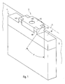
- Fig. 1 shows a sketch of an embodiment of a holding device 2 according to the invention with an attached light 4.
- Fig. 2 the holding device 2 is shown without the lamp.
- the holding device 2 is provided for supporting the lamp 4 on a wall 6, in particular on a vertically extending wall 6 and has a first holding element 8, which is intended to be fixed to the wall 6, and a second holding element 10, the is intended to be fixed in position with the lamp 4.
- first holding element 8 which is intended to be fixed to the wall 6,
- second holding element 10 the is intended to be fixed in position with the lamp 4.
- the first retaining element 8 may have at least one passage opening 81, which is provided for a fixed connection, for example a screw connection with the wall 6.
- the second holding element 10 is arranged opposite the first holding element 8 about a pivot axis S , in particular pivot axis or rotatable.
- a bolt 12 may be provided, which is arranged in the pivot axis S or axis of rotation. It can be provided, in particular, that the second holding element 10 is arranged so as to be movable or pivotable or rotatable relative to the first holding element 8 only about the pivot axis S.
- the bolt 12 and its bearing on the first holding member 8 and the second holding member 10 may accordingly be formed a hinge.
- the embodiment of the holding device 2 is such that the pivoting or rotation axis S is oriented horizontally in the intended orientation of the holding device 2.
- Fig. 3 a schematic cross section is sketched showing the holding device 2, the lamp 4 and the wall 6. Due to the pivotable connection of the two holding elements 8, 10, the lamp 4, starting from a position provided for the operation, swing away from the wall 6 by an angle ⁇ . In this way, in particular a rear area of the lamp 4 is more accessible and the lamp 4 can be easily mounted and also detached from the holding device 2 and from the second holding element 10.
- a tool such as a screwdriver 20 may be provided.
- the holding device 2 may be designed such that the second holding element 10 can be pivoted or rotated relative to the first holding element 8 by at least 40 °, preferably at least 60 °.
- the second support member 10 has support means 14 which are adapted to hold the lamp 4 in its intended for operation alignment from above supporting. This makes it possible that the lamp 4, starting from any deflected position, can be easily pivoted about the pivot axis S in its intended orientation and remains in this, without requiring additional special measures to secure the position or stabilization of the lamp 4 would be required.
- a latching connection is provided between the second holding element 10 and the lamp 4, by which the lamp 4 is held on the second holding element 10, so that both the second holding element 10, and the lamp 10 may have corresponding locking elements.
- the carrying means 14 advantageously comprise at least one latching element 142, which is preferably resilient.
- the carrying means 14 can be formed from a plurality of, for example, four latching elements.
- the locking elements can be designed in this way, in that they can be pushed laterally onto the remaining second holding element 10, for example in pairs, as known per se from the prior art.
- Fig. 3 As an example, it can be provided that in the intended for operation alignment of the lamp 4 with the holding device 2, the support means 14 at least predominantly, preferably completely below a horizontal plane E are arranged, which extends through the pivot axis S. In this way, the lamp 4 depends in its intended orientation particularly stable and secure on the holding device. 2
- the luminaire 4 may have a wiring box 44, wherein the wiring box 44 has the latching elements 46 of the luminaire 4 already mentioned above.
- the lamp 4 may have a device housing 42.
- the latching elements of the luminaire 4 can also be arranged on the device housing 42.
- the second holding element 10 is not displaceable relative to the first holding element 8 along or parallel to the pivot axis S.
- the mobility of the two holding elements 8, 10 is limited to each other and thereby further simplifies the handling of the holding device 2 and the associated lamp 4, in particular in connection with their assembly and disassembly.
- the first holding element 8 comprises a plate-shaped part 82, which is intended to be brought into abutment against the wall 6. This allows a particularly simple mounting of the holding device 2 on the wall 6.
- the at least one passage opening 81 may be formed in the plate-shaped part 82.
- the second holding element 10 advantageously comprises a further plate-shaped part 104, wherein the carrying means 14 or the latching elements 142 extend from the further plate-shaped part 104 projecting downwards.
- the holding device 2 is advantageously designed such that the pivot axis S extends substantially in a plane PE , which is defined by the plate-shaped part 82 of the first holding member 8.
- substantially is to be expressed that the pivot axis S is no further than a small distance from the plane PE , for example, 10%, preferably 5% of the extension L of the second support member 10 in a section normal to the pivot axis S is.
- the first holding element 8 on a spacer 84 which is adapted to hold the lamp 4 in a designated position for operation at a distance A from the wall 6.
- the clearance A secured by the spacer 84 can be, for example, between 5% and 50%, preferably between 10% and 25%, of the extension L of the second holding element 10.
- a second holding element 10 'according to such a variant is in Fig. 3 is indicated in a deflected by the angle ⁇ position.
- the second holding element 10 has a passage opening 102 for carrying out an electrical supply line for the light 4. This makes it particularly easy to produce an electrical supply to the light 4.
Landscapes
- Engineering & Computer Science (AREA)
- General Engineering & Computer Science (AREA)
- Fastening Of Light Sources Or Lamp Holders (AREA)
Claims (10)
- Dispositif de maintien pour le support d'une lampe (4) sur une paroi (6) présentant- un premier élément de maintien (8) qui est prévu afin d'être fixé sur la paroi (6) et- un second élément de maintien (10) qui est prévu afin d'être relié en position fixe à la lampe (4),le second élément de maintien (10) étant disposé de manière pivotante par rapport au premier élément de maintien (8) autour d'un axe de pivotement (S),
le second élément de maintien (10) présentant des moyens porteurs (14) qui sont réalisés afin de maintenir la lampe (4) en la portant par le haut dans son orientation prévue pour le fonctionnement,
le dispositif de maintien étant configuré de sorte que les moyens porteurs (14), si le dispositif de maintien est relié comme prévu à la lampe (4) et la lampe (4) est orientée comme prévu pour le fonctionnement, sont disposés au moins principalement sous un plan horizontal (E) qui s'étend au travers de l'axe de pivotement (S),
le premier élément de maintien (8) comportant une partie en forme de plaque (82) qui est prévue afin d'être amenée en appui contre la paroi (6),
caractérisé en ce que
le dispositif de maintien est configuré de sorte que l'axe de pivotement (S) s'étend sensiblement dans un plan (PE) fixé par la partie en forme de plaque (82), l'axe de pivotement (S) n'étant pas éloigné du plan (PE) de plus de 10 % de l'étendue (L) du second élément de maintien (10) dans une coupe normale à l'axe de pivotement (S). - Dispositif de maintien selon la revendication 1,
qui est configuré de sorte que les moyens porteurs (14), si le dispositif de maintien est relié comme prévu à la lampe (4) et la lampe (4) est orientée comme prévu pour le fonctionnement, sont disposés complètement sous le plan horizontal (E) qui s'étend au travers de l'axe de pivotement (S). - Dispositif de maintien selon la revendication 1 ou 2,
pour lequel l'axe de pivotement (S) n'est pas éloigné du plan (PE) de plus de 5 % de l'étendue (L) du second élément de maintien (10) dans une coupe normale à l'axe de pivotement (S). - Dispositif de maintien selon l'une quelconque des revendications précédentes,
pour lequel les moyens porteurs (14) présentent au moins un élément d'encliquetage (142). - Dispositif de maintien selon la revendication 4,
pour lequel l'élément d'encliquetage (142) est conçu à ressort. - Dispositif de maintien selon l'une quelconque des revendications précédentes,
pour lequel le second élément de maintien (10) est logé de manière non mobile par rapport au premier élément de maintien (8) le long ou parallèlement à l'axe de pivotement (S). - Dispositif de maintien selon l'une quelconque des revendications précédentes,
pour lequel le premier élément de maintien (8) présente un élément d'écartement (84) qui est formé afin de maintenir la lampe (4) dans une position prévue pour le fonctionnement à une distance (A) de la paroi (6). - Dispositif de maintien selon l'une quelconque des revendications précédentes,
pour lequel le second élément de maintien (10) présente une ouverture de passage (102) pour le passage d'un câble d'alimentation électrique pour la lampe (4). - Lampe, en particulier sous la forme d'une lampe de secours reliée à un dispositif de maintien (2) selon l'une quelconque des revendications précédentes.
- Lampe et dispositif de maintien selon la revendication 9,
l'axe de pivotement (S) étant orienté de manière à s'étendre horizontalement dans une position prévue pour le fonctionnement.
Applications Claiming Priority (1)
| Application Number | Priority Date | Filing Date | Title |
|---|---|---|---|
| DE202010013177U DE202010013177U1 (de) | 2010-12-21 | 2010-12-21 | Haltevorrichtung für eine Leuchte |
Publications (3)
| Publication Number | Publication Date |
|---|---|
| EP2469162A2 EP2469162A2 (fr) | 2012-06-27 |
| EP2469162A3 EP2469162A3 (fr) | 2013-07-03 |
| EP2469162B1 true EP2469162B1 (fr) | 2014-08-20 |
Family
ID=45524256
Family Applications (1)
| Application Number | Title | Priority Date | Filing Date |
|---|---|---|---|
| EP20110194492 Not-in-force EP2469162B1 (fr) | 2010-12-21 | 2011-12-20 | Dispositif de support pour une lampe |
Country Status (2)
| Country | Link |
|---|---|
| EP (1) | EP2469162B1 (fr) |
| DE (1) | DE202010013177U1 (fr) |
Families Citing this family (1)
| Publication number | Priority date | Publication date | Assignee | Title |
|---|---|---|---|---|
| DE202012104636U1 (de) | 2012-11-29 | 2014-03-03 | Zumtobel Lighting Gmbh | Halterung für eine Leuchte und Leuchten-Anordnung |
Family Cites Families (11)
| Publication number | Priority date | Publication date | Assignee | Title |
|---|---|---|---|---|
| US4051362A (en) * | 1976-03-08 | 1977-09-27 | Guggemos Kenneth F | Wall mounted hinged base |
| DE2748606C3 (de) * | 1977-10-29 | 1982-01-21 | Abke, Hermann, 4972 Löhne | Befestigungsvorrichtung einer Leuchte |
| DE3008307A1 (de) * | 1980-03-04 | 1981-09-17 | Böllhof & Co, 4800 Bielefeld | Befestigungsbeschlag zur formschluessigen verbindung mindestens zweier mit hinterschneidungen o.dgl. versehener profile |
| AT388986B (de) * | 1987-10-02 | 1989-09-25 | Zumtobel Ag | Moebelanbauleuchte |
| DE9209335U1 (de) * | 1992-07-11 | 1992-09-03 | Licentia Patent-Verwaltungs-Gmbh, 6000 Frankfurt | Haltevorrichtung einer Wandleuchte |
| US5642934A (en) * | 1995-09-13 | 1997-07-01 | Hadco Division Of The Genlyte Group Incorporated | Adjustable outdoor light |
| US6095665A (en) * | 1998-04-03 | 2000-08-01 | Drake; Michael | Outdoor lamp |
| DE20013280U1 (de) * | 2000-08-02 | 2001-12-13 | Kotzolt-Leuchten L. & G. Kotzolt GmbH & Co KG, 32657 Lemgo | Hinweisleuchte |
| US6905222B1 (en) * | 2002-04-02 | 2005-06-14 | Genlyte Thomas Group Llc | Thermal isolation luminaire and wall mount system |
| US7434969B2 (en) * | 2004-01-21 | 2008-10-14 | The Flewelling Ford Family Trust | Multi-function light support |
| DE502006001637D1 (de) * | 2006-04-22 | 2008-11-06 | Gimpel Matthias | Befestigungssystem, insbesondere für Lampen |
-
2010
- 2010-12-21 DE DE202010013177U patent/DE202010013177U1/de not_active Expired - Lifetime
-
2011
- 2011-12-20 EP EP20110194492 patent/EP2469162B1/fr not_active Not-in-force
Also Published As
| Publication number | Publication date |
|---|---|
| EP2469162A2 (fr) | 2012-06-27 |
| DE202010013177U1 (de) | 2012-03-26 |
| EP2469162A3 (fr) | 2013-07-03 |
Similar Documents
| Publication | Publication Date | Title |
|---|---|---|
| EP2248503B1 (fr) | Unité d'alimentation médicale dotée d'adaptateurs réglables | |
| EP2427401B1 (fr) | Elément de suspension d'un dispositif à câble pendant | |
| WO2018157885A1 (fr) | Dispositif de séparation de sécurité conçu pour un connecteur rectangulaire | |
| DE102013108807B4 (de) | Befestigungsvorrichtung für Fahrzeugeinrichtungen | |
| DE102022104333B3 (de) | Halterung zum Halten einer Mensch-Maschine-Schnittstellen-Platine in einer Ladestation und Ladestation | |
| EP2469162B1 (fr) | Dispositif de support pour une lampe | |
| DE202013101819U1 (de) | System zur Montage einer Deckenanbauleuchte an einer Decke | |
| EP1968033B1 (fr) | Dispositif d'affichage doté d'un élément de maintien | |
| EP3737582B1 (fr) | Attache et ensemble support de fil de contact | |
| EP3461963B1 (fr) | Système porteur et système d'éléments de connexion permettant la connexion des porteurs | |
| EP3408156B1 (fr) | Élément de plafond pour un véhicule | |
| EP2879472B1 (fr) | Boîtier pour un appareil de commande | |
| EP3650743B1 (fr) | Dispositif de fixation | |
| EP2578891B1 (fr) | Adapteur | |
| EP2330703A2 (fr) | Agencement destiné à déplacer et fixer un longeron de support et répartiteur d'installation électrique | |
| EP1835580B1 (fr) | Armoire de distribution de câbles ayant des moyens pour empêcher sa rupture | |
| EP2263292B1 (fr) | Dispositif de décharge de traction | |
| AT527582B1 (de) | Platte, insbesondere Zählerplatte | |
| DE1905735A1 (de) | Abhaengbare Deckenkonstruktion | |
| EP3772788A1 (fr) | Élément de fixation et système de fixation | |
| WO2019011378A1 (fr) | Panneau à led muni d'un connecteur pivotant | |
| EP3577725A1 (fr) | Connecteur enfichable équipé d'un pont de connexion de conducteurs de protection | |
| EP4607723A1 (fr) | Bloc de rouleaux avec paires de rouleaux de poulie et axes de rouleaux pivotants | |
| DE202014102924U1 (de) | Elektrischer Anschlusskasten | |
| DE102013104582B4 (de) | Tafel mit Projektionssystem und Halterung zum Anordnen einer Projektionseinrichtung an einer Projektionsfläche |
Legal Events
| Date | Code | Title | Description |
|---|---|---|---|
| AK | Designated contracting states |
Kind code of ref document: A2 Designated state(s): AL AT BE BG CH CY CZ DE DK EE ES FI FR GB GR HR HU IE IS IT LI LT LU LV MC MK MT NL NO PL PT RO RS SE SI SK SM TR |
|
| AX | Request for extension of the european patent |
Extension state: BA ME |
|
| PUAI | Public reference made under article 153(3) epc to a published international application that has entered the european phase |
Free format text: ORIGINAL CODE: 0009012 |
|
| PUAL | Search report despatched |
Free format text: ORIGINAL CODE: 0009013 |
|
| AK | Designated contracting states |
Kind code of ref document: A3 Designated state(s): AL AT BE BG CH CY CZ DE DK EE ES FI FR GB GR HR HU IE IS IT LI LT LU LV MC MK MT NL NO PL PT RO RS SE SI SK SM TR |
|
| AX | Request for extension of the european patent |
Extension state: BA ME |
|
| RIC1 | Information provided on ipc code assigned before grant |
Ipc: F21V 21/02 20060101AFI20130524BHEP |
|
| 17P | Request for examination filed |
Effective date: 20131205 |
|
| RBV | Designated contracting states (corrected) |
Designated state(s): AL AT BE BG CH CY CZ DE DK EE ES FI FR GB GR HR HU IE IS IT LI LT LU LV MC MK MT NL NO PL PT RO RS SE SI SK SM TR |
|
| GRAP | Despatch of communication of intention to grant a patent |
Free format text: ORIGINAL CODE: EPIDOSNIGR1 |
|
| INTG | Intention to grant announced |
Effective date: 20140324 |
|
| GRAS | Grant fee paid |
Free format text: ORIGINAL CODE: EPIDOSNIGR3 |
|
| GRAA | (expected) grant |
Free format text: ORIGINAL CODE: 0009210 |
|
| AK | Designated contracting states |
Kind code of ref document: B1 Designated state(s): AL AT BE BG CH CY CZ DE DK EE ES FI FR GB GR HR HU IE IS IT LI LT LU LV MC MK MT NL NO PL PT RO RS SE SI SK SM TR |
|
| REG | Reference to a national code |
Ref country code: GB Ref legal event code: FG4D Free format text: NOT ENGLISH |
|
| REG | Reference to a national code |
Ref country code: CH Ref legal event code: EP Ref country code: CH Ref legal event code: NV Representative=s name: FIAMMENGHI-FIAMMENGHI, CH |
|
| REG | Reference to a national code |
Ref country code: AT Ref legal event code: REF Ref document number: 683678 Country of ref document: AT Kind code of ref document: T Effective date: 20140915 |
|
| REG | Reference to a national code |
Ref country code: IE Ref legal event code: FG4D Free format text: LANGUAGE OF EP DOCUMENT: GERMAN |
|
| REG | Reference to a national code |
Ref country code: DE Ref legal event code: R096 Ref document number: 502011004096 Country of ref document: DE Effective date: 20141002 |
|
| REG | Reference to a national code |
Ref country code: NL Ref legal event code: VDEP Effective date: 20140820 |
|
| REG | Reference to a national code |
Ref country code: LT Ref legal event code: MG4D |
|
| PG25 | Lapsed in a contracting state [announced via postgrant information from national office to epo] |
Ref country code: FI Free format text: LAPSE BECAUSE OF FAILURE TO SUBMIT A TRANSLATION OF THE DESCRIPTION OR TO PAY THE FEE WITHIN THE PRESCRIBED TIME-LIMIT Effective date: 20140820 Ref country code: LT Free format text: LAPSE BECAUSE OF FAILURE TO SUBMIT A TRANSLATION OF THE DESCRIPTION OR TO PAY THE FEE WITHIN THE PRESCRIBED TIME-LIMIT Effective date: 20140820 Ref country code: SE Free format text: LAPSE BECAUSE OF FAILURE TO SUBMIT A TRANSLATION OF THE DESCRIPTION OR TO PAY THE FEE WITHIN THE PRESCRIBED TIME-LIMIT Effective date: 20140820 Ref country code: NO Free format text: LAPSE BECAUSE OF FAILURE TO SUBMIT A TRANSLATION OF THE DESCRIPTION OR TO PAY THE FEE WITHIN THE PRESCRIBED TIME-LIMIT Effective date: 20141120 Ref country code: ES Free format text: LAPSE BECAUSE OF FAILURE TO SUBMIT A TRANSLATION OF THE DESCRIPTION OR TO PAY THE FEE WITHIN THE PRESCRIBED TIME-LIMIT Effective date: 20140820 Ref country code: PT Free format text: LAPSE BECAUSE OF FAILURE TO SUBMIT A TRANSLATION OF THE DESCRIPTION OR TO PAY THE FEE WITHIN THE PRESCRIBED TIME-LIMIT Effective date: 20141222 Ref country code: BG Free format text: LAPSE BECAUSE OF FAILURE TO SUBMIT A TRANSLATION OF THE DESCRIPTION OR TO PAY THE FEE WITHIN THE PRESCRIBED TIME-LIMIT Effective date: 20141120 Ref country code: GR Free format text: LAPSE BECAUSE OF FAILURE TO SUBMIT A TRANSLATION OF THE DESCRIPTION OR TO PAY THE FEE WITHIN THE PRESCRIBED TIME-LIMIT Effective date: 20141121 |
|
| PG25 | Lapsed in a contracting state [announced via postgrant information from national office to epo] |
Ref country code: LV Free format text: LAPSE BECAUSE OF FAILURE TO SUBMIT A TRANSLATION OF THE DESCRIPTION OR TO PAY THE FEE WITHIN THE PRESCRIBED TIME-LIMIT Effective date: 20140820 Ref country code: HR Free format text: LAPSE BECAUSE OF FAILURE TO SUBMIT A TRANSLATION OF THE DESCRIPTION OR TO PAY THE FEE WITHIN THE PRESCRIBED TIME-LIMIT Effective date: 20140820 Ref country code: RS Free format text: LAPSE BECAUSE OF FAILURE TO SUBMIT A TRANSLATION OF THE DESCRIPTION OR TO PAY THE FEE WITHIN THE PRESCRIBED TIME-LIMIT Effective date: 20140820 Ref country code: IS Free format text: LAPSE BECAUSE OF FAILURE TO SUBMIT A TRANSLATION OF THE DESCRIPTION OR TO PAY THE FEE WITHIN THE PRESCRIBED TIME-LIMIT Effective date: 20141220 |
|
| PG25 | Lapsed in a contracting state [announced via postgrant information from national office to epo] |
Ref country code: NL Free format text: LAPSE BECAUSE OF FAILURE TO SUBMIT A TRANSLATION OF THE DESCRIPTION OR TO PAY THE FEE WITHIN THE PRESCRIBED TIME-LIMIT Effective date: 20140820 |
|
| PG25 | Lapsed in a contracting state [announced via postgrant information from national office to epo] |
Ref country code: RO Free format text: LAPSE BECAUSE OF FAILURE TO SUBMIT A TRANSLATION OF THE DESCRIPTION OR TO PAY THE FEE WITHIN THE PRESCRIBED TIME-LIMIT Effective date: 20140820 Ref country code: IT Free format text: LAPSE BECAUSE OF FAILURE TO SUBMIT A TRANSLATION OF THE DESCRIPTION OR TO PAY THE FEE WITHIN THE PRESCRIBED TIME-LIMIT Effective date: 20140820 Ref country code: SK Free format text: LAPSE BECAUSE OF FAILURE TO SUBMIT A TRANSLATION OF THE DESCRIPTION OR TO PAY THE FEE WITHIN THE PRESCRIBED TIME-LIMIT Effective date: 20140820 Ref country code: DK Free format text: LAPSE BECAUSE OF FAILURE TO SUBMIT A TRANSLATION OF THE DESCRIPTION OR TO PAY THE FEE WITHIN THE PRESCRIBED TIME-LIMIT Effective date: 20140820 Ref country code: CZ Free format text: LAPSE BECAUSE OF FAILURE TO SUBMIT A TRANSLATION OF THE DESCRIPTION OR TO PAY THE FEE WITHIN THE PRESCRIBED TIME-LIMIT Effective date: 20140820 Ref country code: EE Free format text: LAPSE BECAUSE OF FAILURE TO SUBMIT A TRANSLATION OF THE DESCRIPTION OR TO PAY THE FEE WITHIN THE PRESCRIBED TIME-LIMIT Effective date: 20140820 |
|
| REG | Reference to a national code |
Ref country code: DE Ref legal event code: R097 Ref document number: 502011004096 Country of ref document: DE |
|
| PG25 | Lapsed in a contracting state [announced via postgrant information from national office to epo] |
Ref country code: PL Free format text: LAPSE BECAUSE OF FAILURE TO SUBMIT A TRANSLATION OF THE DESCRIPTION OR TO PAY THE FEE WITHIN THE PRESCRIBED TIME-LIMIT Effective date: 20140820 |
|
| PLBE | No opposition filed within time limit |
Free format text: ORIGINAL CODE: 0009261 |
|
| STAA | Information on the status of an ep patent application or granted ep patent |
Free format text: STATUS: NO OPPOSITION FILED WITHIN TIME LIMIT |
|
| PG25 | Lapsed in a contracting state [announced via postgrant information from national office to epo] |
Ref country code: BE Free format text: LAPSE BECAUSE OF NON-PAYMENT OF DUE FEES Effective date: 20141231 |
|
| 26N | No opposition filed |
Effective date: 20150521 |
|
| PG25 | Lapsed in a contracting state [announced via postgrant information from national office to epo] |
Ref country code: LU Free format text: LAPSE BECAUSE OF FAILURE TO SUBMIT A TRANSLATION OF THE DESCRIPTION OR TO PAY THE FEE WITHIN THE PRESCRIBED TIME-LIMIT Effective date: 20141220 |
|
| REG | Reference to a national code |
Ref country code: IE Ref legal event code: MM4A |
|
| PG25 | Lapsed in a contracting state [announced via postgrant information from national office to epo] |
Ref country code: IE Free format text: LAPSE BECAUSE OF NON-PAYMENT OF DUE FEES Effective date: 20141220 |
|
| PG25 | Lapsed in a contracting state [announced via postgrant information from national office to epo] |
Ref country code: SI Free format text: LAPSE BECAUSE OF FAILURE TO SUBMIT A TRANSLATION OF THE DESCRIPTION OR TO PAY THE FEE WITHIN THE PRESCRIBED TIME-LIMIT Effective date: 20140820 |
|
| REG | Reference to a national code |
Ref country code: FR Ref legal event code: PLFP Year of fee payment: 5 |
|
| PG25 | Lapsed in a contracting state [announced via postgrant information from national office to epo] |
Ref country code: SM Free format text: LAPSE BECAUSE OF FAILURE TO SUBMIT A TRANSLATION OF THE DESCRIPTION OR TO PAY THE FEE WITHIN THE PRESCRIBED TIME-LIMIT Effective date: 20140820 |
|
| PG25 | Lapsed in a contracting state [announced via postgrant information from national office to epo] |
Ref country code: MC Free format text: LAPSE BECAUSE OF FAILURE TO SUBMIT A TRANSLATION OF THE DESCRIPTION OR TO PAY THE FEE WITHIN THE PRESCRIBED TIME-LIMIT Effective date: 20140820 |
|
| PG25 | Lapsed in a contracting state [announced via postgrant information from national office to epo] |
Ref country code: CY Free format text: LAPSE BECAUSE OF FAILURE TO SUBMIT A TRANSLATION OF THE DESCRIPTION OR TO PAY THE FEE WITHIN THE PRESCRIBED TIME-LIMIT Effective date: 20140820 |
|
| PG25 | Lapsed in a contracting state [announced via postgrant information from national office to epo] |
Ref country code: HU Free format text: LAPSE BECAUSE OF FAILURE TO SUBMIT A TRANSLATION OF THE DESCRIPTION OR TO PAY THE FEE WITHIN THE PRESCRIBED TIME-LIMIT; INVALID AB INITIO Effective date: 20111220 Ref country code: TR Free format text: LAPSE BECAUSE OF FAILURE TO SUBMIT A TRANSLATION OF THE DESCRIPTION OR TO PAY THE FEE WITHIN THE PRESCRIBED TIME-LIMIT Effective date: 20140820 Ref country code: MT Free format text: LAPSE BECAUSE OF FAILURE TO SUBMIT A TRANSLATION OF THE DESCRIPTION OR TO PAY THE FEE WITHIN THE PRESCRIBED TIME-LIMIT Effective date: 20140820 |
|
| REG | Reference to a national code |
Ref country code: FR Ref legal event code: PLFP Year of fee payment: 6 |
|
| PGFP | Annual fee paid to national office [announced via postgrant information from national office to epo] |
Ref country code: CH Payment date: 20161223 Year of fee payment: 6 Ref country code: GB Payment date: 20161228 Year of fee payment: 6 |
|
| PGFP | Annual fee paid to national office [announced via postgrant information from national office to epo] |
Ref country code: AT Payment date: 20170105 Year of fee payment: 6 Ref country code: FR Payment date: 20161229 Year of fee payment: 6 |
|
| PG25 | Lapsed in a contracting state [announced via postgrant information from national office to epo] |
Ref country code: MK Free format text: LAPSE BECAUSE OF FAILURE TO SUBMIT A TRANSLATION OF THE DESCRIPTION OR TO PAY THE FEE WITHIN THE PRESCRIBED TIME-LIMIT Effective date: 20140820 |
|
| REG | Reference to a national code |
Ref country code: CH Ref legal event code: PL |
|
| REG | Reference to a national code |
Ref country code: AT Ref legal event code: MM01 Ref document number: 683678 Country of ref document: AT Kind code of ref document: T Effective date: 20171220 |
|
| GBPC | Gb: european patent ceased through non-payment of renewal fee |
Effective date: 20171220 |
|
| REG | Reference to a national code |
Ref country code: FR Ref legal event code: ST Effective date: 20180831 |
|
| REG | Reference to a national code |
Ref country code: DE Ref legal event code: R084 Ref document number: 502011004096 Country of ref document: DE |
|
| PG25 | Lapsed in a contracting state [announced via postgrant information from national office to epo] |
Ref country code: AL Free format text: LAPSE BECAUSE OF FAILURE TO SUBMIT A TRANSLATION OF THE DESCRIPTION OR TO PAY THE FEE WITHIN THE PRESCRIBED TIME-LIMIT Effective date: 20140820 Ref country code: FR Free format text: LAPSE BECAUSE OF NON-PAYMENT OF DUE FEES Effective date: 20180102 |
|
| PG25 | Lapsed in a contracting state [announced via postgrant information from national office to epo] |
Ref country code: GB Free format text: LAPSE BECAUSE OF NON-PAYMENT OF DUE FEES Effective date: 20171220 Ref country code: AT Free format text: LAPSE BECAUSE OF NON-PAYMENT OF DUE FEES Effective date: 20171220 Ref country code: CH Free format text: LAPSE BECAUSE OF NON-PAYMENT OF DUE FEES Effective date: 20171231 Ref country code: LI Free format text: LAPSE BECAUSE OF NON-PAYMENT OF DUE FEES Effective date: 20171231 |
|
| PGFP | Annual fee paid to national office [announced via postgrant information from national office to epo] |
Ref country code: DE Payment date: 20220527 Year of fee payment: 12 |
|
| P01 | Opt-out of the competence of the unified patent court (upc) registered |
Effective date: 20230530 |
|
| REG | Reference to a national code |
Ref country code: DE Ref legal event code: R119 Ref document number: 502011004096 Country of ref document: DE |
|
| PG25 | Lapsed in a contracting state [announced via postgrant information from national office to epo] |
Ref country code: DE Free format text: LAPSE BECAUSE OF NON-PAYMENT OF DUE FEES Effective date: 20240702 |
|
| PG25 | Lapsed in a contracting state [announced via postgrant information from national office to epo] |
Ref country code: DE Free format text: LAPSE BECAUSE OF NON-PAYMENT OF DUE FEES Effective date: 20240702 |