EP3516435B1 - Fibres optiques à indice de gaine variable et leurs procédés de formation - Google Patents
Fibres optiques à indice de gaine variable et leurs procédés de formation Download PDFInfo
- Publication number
- EP3516435B1 EP3516435B1 EP17849819.2A EP17849819A EP3516435B1 EP 3516435 B1 EP3516435 B1 EP 3516435B1 EP 17849819 A EP17849819 A EP 17849819A EP 3516435 B1 EP3516435 B1 EP 3516435B1
- Authority
- EP
- European Patent Office
- Prior art keywords
- soot
- optical fiber
- chlorine
- preform
- profile
- Prior art date
- Legal status (The legal status is an assumption and is not a legal conclusion. Google has not performed a legal analysis and makes no representation as to the accuracy of the status listed.)
- Active
Links
Images


Classifications
-
- G—PHYSICS
- G02—OPTICS
- G02B—OPTICAL ELEMENTS, SYSTEMS OR APPARATUS
- G02B6/00—Light guides; Structural details of arrangements comprising light guides and other optical elements, e.g. couplings
- G02B6/02—Optical fibres with cladding with or without a coating
- G02B6/028—Optical fibres with cladding with or without a coating with core or cladding having graded refractive index
- G02B6/0286—Combination of graded index in the central core segment and a graded index layer external to the central core segment
-
- C—CHEMISTRY; METALLURGY
- C03—GLASS; MINERAL OR SLAG WOOL
- C03B—MANUFACTURE, SHAPING, OR SUPPLEMENTARY PROCESSES
- C03B37/00—Manufacture or treatment of flakes, fibres, or filaments from softened glass, minerals, or slags
- C03B37/01—Manufacture of glass fibres or filaments
- C03B37/012—Manufacture of preforms for drawing fibres or filaments
- C03B37/014—Manufacture of preforms for drawing fibres or filaments made entirely or partially by chemical means, e.g. vapour phase deposition of bulk porous glass either by outside vapour deposition [OVD], or by outside vapour phase oxidation [OVPO] or by vapour axial deposition [VAD]
- C03B37/01413—Reactant delivery systems
-
- C—CHEMISTRY; METALLURGY
- C03—GLASS; MINERAL OR SLAG WOOL
- C03B—MANUFACTURE, SHAPING, OR SUPPLEMENTARY PROCESSES
- C03B37/00—Manufacture or treatment of flakes, fibres, or filaments from softened glass, minerals, or slags
- C03B37/01—Manufacture of glass fibres or filaments
- C03B37/012—Manufacture of preforms for drawing fibres or filaments
- C03B37/014—Manufacture of preforms for drawing fibres or filaments made entirely or partially by chemical means, e.g. vapour phase deposition of bulk porous glass either by outside vapour deposition [OVD], or by outside vapour phase oxidation [OVPO] or by vapour axial deposition [VAD]
- C03B37/01446—Thermal after-treatment of preforms, e.g. dehydrating, consolidating, sintering
-
- C—CHEMISTRY; METALLURGY
- C03—GLASS; MINERAL OR SLAG WOOL
- C03B—MANUFACTURE, SHAPING, OR SUPPLEMENTARY PROCESSES
- C03B37/00—Manufacture or treatment of flakes, fibres, or filaments from softened glass, minerals, or slags
- C03B37/01—Manufacture of glass fibres or filaments
- C03B37/012—Manufacture of preforms for drawing fibres or filaments
- C03B37/014—Manufacture of preforms for drawing fibres or filaments made entirely or partially by chemical means, e.g. vapour phase deposition of bulk porous glass either by outside vapour deposition [OVD], or by outside vapour phase oxidation [OVPO] or by vapour axial deposition [VAD]
- C03B37/01466—Means for changing or stabilising the diameter or form of tubes or rods
-
- C—CHEMISTRY; METALLURGY
- C03—GLASS; MINERAL OR SLAG WOOL
- C03B—MANUFACTURE, SHAPING, OR SUPPLEMENTARY PROCESSES
- C03B37/00—Manufacture or treatment of flakes, fibres, or filaments from softened glass, minerals, or slags
- C03B37/01—Manufacture of glass fibres or filaments
- C03B37/012—Manufacture of preforms for drawing fibres or filaments
- C03B37/014—Manufacture of preforms for drawing fibres or filaments made entirely or partially by chemical means, e.g. vapour phase deposition of bulk porous glass either by outside vapour deposition [OVD], or by outside vapour phase oxidation [OVPO] or by vapour axial deposition [VAD]
- C03B37/018—Manufacture of preforms for drawing fibres or filaments made entirely or partially by chemical means, e.g. vapour phase deposition of bulk porous glass either by outside vapour deposition [OVD], or by outside vapour phase oxidation [OVPO] or by vapour axial deposition [VAD] by glass deposition on a glass substrate, e.g. by inside-, modified-, plasma-, or plasma modified- chemical vapour deposition [ICVD, MCVD, PCVD, PMCVD], i.e. by thin layer coating on the inside or outside of a glass tube or on a glass rod
-
- G—PHYSICS
- G02—OPTICS
- G02B—OPTICAL ELEMENTS, SYSTEMS OR APPARATUS
- G02B6/00—Light guides; Structural details of arrangements comprising light guides and other optical elements, e.g. couplings
- G02B6/02—Optical fibres with cladding with or without a coating
- G02B6/02214—Optical fibres with cladding with or without a coating tailored to obtain the desired dispersion, e.g. dispersion shifted, dispersion flattened
-
- G—PHYSICS
- G02—OPTICS
- G02B—OPTICAL ELEMENTS, SYSTEMS OR APPARATUS
- G02B6/00—Light guides; Structural details of arrangements comprising light guides and other optical elements, e.g. couplings
- G02B6/02—Optical fibres with cladding with or without a coating
- G02B6/028—Optical fibres with cladding with or without a coating with core or cladding having graded refractive index
- G02B6/0283—Graded index region external to the central core segment, e.g. sloping layer or triangular or trapezoidal layer
-
- G—PHYSICS
- G02—OPTICS
- G02B—OPTICAL ELEMENTS, SYSTEMS OR APPARATUS
- G02B6/00—Light guides; Structural details of arrangements comprising light guides and other optical elements, e.g. couplings
- G02B6/02—Optical fibres with cladding with or without a coating
- G02B6/036—Optical fibres with cladding with or without a coating core or cladding comprising multiple layers
- G02B6/03616—Optical fibres characterised both by the number of different refractive index layers around the central core segment, i.e. around the innermost high index core layer, and their relative refractive index difference
- G02B6/03622—Optical fibres characterised both by the number of different refractive index layers around the central core segment, i.e. around the innermost high index core layer, and their relative refractive index difference having 2 layers only
- G02B6/03627—Optical fibres characterised both by the number of different refractive index layers around the central core segment, i.e. around the innermost high index core layer, and their relative refractive index difference having 2 layers only arranged - +
-
- G—PHYSICS
- G02—OPTICS
- G02B—OPTICAL ELEMENTS, SYSTEMS OR APPARATUS
- G02B6/00—Light guides; Structural details of arrangements comprising light guides and other optical elements, e.g. couplings
- G02B6/02—Optical fibres with cladding with or without a coating
- G02B6/036—Optical fibres with cladding with or without a coating core or cladding comprising multiple layers
- G02B6/03616—Optical fibres characterised both by the number of different refractive index layers around the central core segment, i.e. around the innermost high index core layer, and their relative refractive index difference
- G02B6/03638—Optical fibres characterised both by the number of different refractive index layers around the central core segment, i.e. around the innermost high index core layer, and their relative refractive index difference having 3 layers only
- G02B6/03644—Optical fibres characterised both by the number of different refractive index layers around the central core segment, i.e. around the innermost high index core layer, and their relative refractive index difference having 3 layers only arranged - + -
-
- C—CHEMISTRY; METALLURGY
- C03—GLASS; MINERAL OR SLAG WOOL
- C03B—MANUFACTURE, SHAPING, OR SUPPLEMENTARY PROCESSES
- C03B2201/00—Type of glass produced
- C03B2201/06—Doped silica-based glasses
- C03B2201/08—Doped silica-based glasses doped with boron or fluorine or other refractive index decreasing dopant
-
- C—CHEMISTRY; METALLURGY
- C03—GLASS; MINERAL OR SLAG WOOL
- C03B—MANUFACTURE, SHAPING, OR SUPPLEMENTARY PROCESSES
- C03B2201/00—Type of glass produced
- C03B2201/06—Doped silica-based glasses
- C03B2201/20—Doped silica-based glasses doped with non-metals other than boron or fluorine
-
- C—CHEMISTRY; METALLURGY
- C03—GLASS; MINERAL OR SLAG WOOL
- C03B—MANUFACTURE, SHAPING, OR SUPPLEMENTARY PROCESSES
- C03B2207/00—Glass deposition burners
- C03B2207/70—Control measures
-
- C—CHEMISTRY; METALLURGY
- C03—GLASS; MINERAL OR SLAG WOOL
- C03B—MANUFACTURE, SHAPING, OR SUPPLEMENTARY PROCESSES
- C03B37/00—Manufacture or treatment of flakes, fibres, or filaments from softened glass, minerals, or slags
- C03B37/01—Manufacture of glass fibres or filaments
- C03B37/02—Manufacture of glass fibres or filaments by drawing or extruding, e.g. direct drawing of molten glass from nozzles; Cooling fins therefor
- C03B37/025—Manufacture of glass fibres or filaments by drawing or extruding, e.g. direct drawing of molten glass from nozzles; Cooling fins therefor from reheated softened tubes, rods, fibres or filaments, e.g. drawing fibres from preforms
Definitions
- the present disclosure relates generally to optical fibers, and particularly to low attenuation optical fibers with a varying clad index and methods of forming same.
- JP2002053344 discloses a glass preform made of quartz comprising a core part obtained by forming a part of a clad around a Ge doped core and a clad part, the preform having a chlorine concentration distribution in the radial direction formed by doping with chlorine and a part with a low chlorine concentration near the interface between the core and clad parts.
- JPH02139504 discloses an optical fiber wherein the refractive index can be changed after manufacture.
- an optical fiber according to claim 1 there is provided an optical fiber according to claim 1.
- an updopant is a material or dopant that increases the refractive index of the glass relative to pure silica.
- Such updopants may be, for example, chlorine, germania, N, phosphorous, titania or alumina.
- the "relative refractive index profile,” as used herein, is the relationship between the relative refractive index (defined below) and fiber radius of a radial cross section of the optical fiber.
- delta, delta index, delta index percent, ⁇ , ⁇ % are used interchangeably herein.
- the terms ⁇ i MAX and ⁇ i MIN respectively refer to the maximum relative refractive index and the minimum relative refractive index for the region i of the optical fiber.
- index profile means a refractive index profile, a relative refractive index profile, a normalized refractive index profile or any other profile that is based on the refractive index.
- index parameter is used to denote a parameter used to describe an index profile.
- the index parameter is ⁇ , the relative refractive index
- the index parameter is the normalized refractive index N.
- pure silica glass means that the region or layer of the optical fiber comprising "pure silica glass” does not contain material, such as dopants and/or other trace materials, in an amount which would significantly alter the refractive index of the silica glass region or portion.
- dopants e.g., chlorine and/or fluorine in an amount less than 1500 ppm of each
- siliconca or “pure silica.”
- Chromatic dispersion (which may be referred to herein as “dispersion” unless otherwise noted) of a waveguide fiber is the sum of the material dispersion and the waveguide dispersion.
- a zero dispersion wavelength is a wavelength at which the dispersion has a value of zero and also referred to herein as Lambda 0 or ⁇ 0 .
- Dispersion slope is the rate of change of dispersion with respect to wavelength.
- a-profile refers to a relative refractive index profile of the core region expressed in terms of ⁇ (r) which is in units of "%", where r is radius.
- the bend resistance of a waveguide fiber can be gauged by induced attenuation under prescribed test conditions.
- Mandrel wrap is a macrobending test, lateral load and pin array are microbending tests. Data in Table 1 includes values for both types of loss.
- the mandrel wrap test is one test used to determine macrobending loss (macro BL).
- an optical fiber is wrapped around a mandrel having a prescribed diameter, e.g., the optical fiber is wrapped 1 turn around a 6 mm, 10 mm, 20 mm, 30 mm or other specified diameter mandrel (e.g.
- micro BL microbending loss
- the fiber sample was wound to an aluminum drum that was wrapped with fine wire mesh.
- the barrel surface of the aluminum drum was covered with wire mesh and the fiber was wrapped around the wire mesh.
- the mesh was wrapped tightly around the barrel without stretching and was kept intact without holes, dips, tearing, or damage.
- the wire mesh material used in the measurements was made from corrosion-resistant type 304 stainless steel woven wire cloth and had the following characteristics: mesh per linear inch: 165x165, wire diameter: 48.3 ⁇ m (0.0019"), width opening: 104.1 ⁇ m (0.0041”), and open area %: 44.0.
- a 750 m length of coated fiber was wound at 1 m/s on the wire mesh covered drum at 0.050 cm take-up pitch while applying 80 (+/-1) grams of tension.
- the ends of the fiber were taped to maintain tension and there were no fiber crossovers.
- the points of contact of the wound fiber with the mesh impart stress to the fiber and the attenuation of light through the wound fiber is a measure of stress-induced (microbending) losses of the fiber.
- the wire drum measurement was performed after a dwell time of 1 -hour.
- the increase in fiber attenuation (in dB/km) in the measurement performed in the second configuration (wire mesh covered drum) relative to the first configuration (smooth drum) was determined for each wavelength.
- the average of three trials was determined at each wavelength and is reported as the wire mesh microbend loss of the coated fibers in Table 1.
- cabled cutoff wavelength or “cabled cutoff' as used herein, we mean the 22 m cabled cutoff test described in the EIA-445 Fiber Optic Test Procedures, which are part of the EIA-TIA Fiber Optics Standards, that is, the Electronics Industry Alliance - Telecommunications Industry Association Fiber Optics Standards.
- optical properties (such as dispersion, dispersion slope, etc.) are reported for the LP01 mode.
- region B immediately surrounding region A means that region B is in direct contact with region A.
- core cane refers to a doped silica cane used to make optical fiber.
- the core cane has a doped central core region that is surrounded by a silica cladding.
- the core cane is consolidated glass.
- ⁇ m refers to distance in microns.
- low-index trench region and “trench region” as used herein, refer to a portion of the optical preform or optical fiber that comprises an index-lowering dopant relative to pure silica. It should also be understood that the "lower index trench region” and “trench region,” terms, as used herein, also include interim regions of the fiber or preform that contain doped soot that has not yet been consolidated, but will ultimately define a consolidated region containing the index-lowering dopant.
- Dopant concentrations in the optical preform and/or fiber are expressed herein on the basis of weight (e.g., ppm by weight, ppm (by weight), percent by weight, wt. %), unless otherwise specified.
- Concentrations of components in the gas phase are expressed herein on the basis of volume (e.g., ppm by volume, ppm (by volume), percent by volume, vol. %).
- silicon-based glass soot silica-based soot
- siO 2 or doped-SiO 2 particles SiO 2 or doped-SiO 2 particles.
- individual soot particles generally have a size of about 5 nm to about 10 microns in diameter and, in some embodiments, about 5 nm to about 1 micron in diameter.
- soot preform refers to an article made of soot particles that has at least some open porosity.
- partially consolidated soot preform refers to a soot preform that has been subjected to a consolidating step to partially close pores. As the extent of consolidation increases, pores become increasingly closed and pore volume progressively decreases.
- consolidated glass refers to glass in a closed-pore state. In some embodiments, the glass is void-free.
- the term "consolidating” refers to the step of going from a porous glass state to a closed-porosity state. In some embodiments, the glass becomes void-free in the consolidating step.
- optical fiber preform refers to a glass article from which an optical fiber can be drawn.
- optical fiber preform(s) and “optical fiber blank(s)” are used interchangeably.
- FIG. 1A is an isometric view and FIG. 1B is a schematic cross-sectional view of an example optical fiber 6 as disclosed herein.
- Embodiments of optical fibers 6 described herein generally comprise a single mode optical fiber having a core 10 centered on a central axis AC.
- the optical fiber 6 also has an inner cladding 20 (also referred to herein as an inner cladding layer) that immediately surrounds core 10, and an outer cladding 30 (also referred to as outer cladding layer) immediately surrounds the inner cladding.
- the inner cladding 20 and outer cladding 30 constitute a general cladding 40.
- the core 10 (also referred to herein as a core layer and a core portion) has a relative refractive index ⁇ 1 that varies with radial coordinate (radius) r and thus can be represented as ⁇ 1 (r).
- the core 10 has a radius r 1 , which defines the inner radius of inner cladding 20.
- the core radius r 1 is in the range from 6 microns to 8 microns.
- r 3 62.5 ⁇ m.
- thickness T 2 is in the range from 8 microns to 9 microns.
- radial thickness T 3 is in the range from 45 microns to 48 microns.
- the radii r 1 , r 2 and r 3 are the outer radii of core 10, inner cladding 20 and outer cladding 30, respectively.
- r 2 is greater than 9 microns. In some embodiments r 2 is greater than or equal to 12 microns. In some embodiments r 2 is greater than or equal to 15 microns. In some embodiments r 2 is less than or equal to 25 microns. In some embodiments r 2 is greater than 9 microns and less than or equal to 25 microns.
- FIGS. 2A and 2B are idealized index profile plots that show the relative refractive index ⁇ % versus fiber radius r ( ⁇ m) for examples of optical fiber 6. The plot is not to scale to highlight select features of the relative refractive index profiles.
- the inner cladding 20 has a relative refractive index ⁇ 2 , wherein ⁇ 1MAX > ⁇ 2 .
- the relative refractive index ⁇ 2 can also vary with radius r and so can be represented as ⁇ 2 (r).
- the relative refractive index ⁇ 2 can also have maximum and minimum values ⁇ 2MAX and ⁇ 2MIN , respectively.
- ⁇ 2MIN 0, i.e., the calculation of the relative refractive index ⁇ is performed such that the lowest value of ⁇ is ⁇ 2MIN .
- the outer cladding 30 has a relative refractive index ⁇ 3 that varies with radius r and thus can be represented as ⁇ 3 (r).
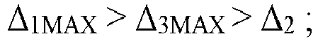
- the relative refractive index ⁇ 3 includes a maximum value ⁇ 3MAX , wherein ⁇ 1MAX > ⁇ 3MAX > ⁇ 2 .
- the relative refractive index ⁇ 3 of outer cladding 30 includes a minimum value ⁇ 3MIN .
- ⁇ 3 MAX ⁇ ⁇ 3 MIN 0.01 ⁇ % .
- ⁇ 3MAX - ⁇ 3MIN ⁇ 0.03 ⁇ %. In some embodiments ⁇ 3MAX - ⁇ 3MIN ⁇ 0.05 ⁇ %. In some embodiments ⁇ 3MAX - ⁇ 3MIN ⁇ 0.08 ⁇ %.
- the core 10, inner cladding 20 and outer cladding 30 may comprise dopants, as described in more detail herein.
- the cross section of the optical fiber 6 may be generally circular-symmetric with respect to central axis AC.
- the graded index core 10 has a core alpha that is less than 10, in some embodiments, the graded index core 10 has a core alpha that is less than 5, and in some embodiments, the graded index core 10 has a core alpha that is less than 3. In some embodiments, the graded index core 10 has a core alpha that is less than 3 and greater than 1. In some embodiments, the graded index core 10 has a core alpha that is less than 2.5 and greater than 1.5.
- the difference between the relative refractive index ⁇ 3MAX of outer cladding 30 and that of inner cladding 20 is ⁇ 3 - ⁇ 2 and is positive and is greater than 0.005 ⁇ %, or more preferably is greater than or equal to 0.015 ⁇ % or even more preferably is greater than or equal to 0.025 %.
- ⁇ 3 - ⁇ 2 is defined as ⁇ 3MAX - ⁇ 2MIN , wherein ⁇ 2MIN is zero.
- FIGS. 2A and 2B show the curved shape of relative refractive index ⁇ 3 of outer cladding 30.
- r MIN > r MAX .
- ⁇ 2 has a constant value, though as noted above ⁇ 2 can also vary with radial coordinate r, and in practice for actual fabricated optical fibers 6, ⁇ 2 may vary with radial coordinate due to manufacturing effects.
- Table 1 below sets forth example parameters for three example optical fibers 6 denoted EX 0, EX 1 and EX 2, which have relative refractive index profiles P0, P1, and P2 shown in Figs 3A-3C , respectively.
- BL stands for "bend loss.”
- the macro BL data was obtained using the mandrel wrap test described above and the micro BL data were obtained using the wire mesh drum test described above.
- C max " and "C min” stands for "maximum chlorine concentration” and “minimum chlorine concentration", respectively.
- FIG. 3A is a plot of ⁇ % versus fiber radius r ( ⁇ m) for an example baseline profile (P0) for example optical fiber EX 0.
- FIGS. 3B and 3C are similar plots to FIG. 3A and include baseline profile P0 and respective additional profiles P1 and P2 for example optical fibers EX 1 and EX 2, wherein the ⁇ % axis is amplified to show the detail of the shape of the profile for outer cladding 30.
- FIGS. 4A and 4B are plots of the simulated cutoff signal SCS (dB) versus wavelength (nm) that show modeled cutoff traces for baseline profile P0 as well as for profile P1 ( FIG. 4A ) and profile P2 ( FIG. 4B ). The plots of FIGS.
- the chlorine concentration C(r) thus has a gradient concentration profile with a maximum value C MAX and a minimum concentration C MIN .
- r C_MAX is between r 2 and r 2 + T 3 /2 ( FIG. 2B ).
- r C_MIN is between r 2 + T 3 /2 and r 3 .
- C MAX is at least 1000 ppm greater than C MIN . In another embodiment, C MAX is at least 1500 parts per million (ppm) greater than C MIN . In another embodiment, C MAX is at least 1700 parts per million (ppm) greater than C MIN . In another embodiment, C MAX is at least 2,000 ppm greater than C MIN .
- optical fiber 6 has an attenuation of less than 0.185 dB/km at a wavelength of 1550 nm. Also in an example, optical fiber 6 has a macro bend loss for a 20 mm diameter mandrel of less than 0.2 dB/turn at a wavelength of 1550 nm. Also in an example, optical fiber 6 has a zero dispersion wavelength ⁇ 0 , wherein 1300 nm ⁇ ⁇ 0 ⁇ 1324 nm. In another example, optical fiber 6 has an MFD at a wavelength of 1310 nm between 8.8 microns and 9.5 microns. In another example, optical fiber 6 has a cabled cutoff wavelength of less than or equal to 1260 nm. The optical fiber 6 can have one or more of the above-identified characteristics, including all of the above-identified characteristics.
- the invention comprises a method of forming an optical fiber according to claim 8.
- tailored radial soot density profile refers herein to a predetermined radial density profile of silica or doped silica soot that corresponds to the soot portion of an optical preform.
- FIG. 5 is a schematic diagram of an example drawing system 200 for producing optical fiber 6 as disclosed herein.
- the system 200 may comprise a draw furnace 202 for heating a glass optical fiber preform ("glass preform") 204 such that an optical fiber 100 may be drawn from the glass preform.
- the glass preform 204 may be produced by an outside vapor deposition (OVD) method and may be formed as discussed below.
- ODD outside vapor deposition
- the configuration of glass preform 204 and the various drawing parameters dictate the final form of optical fiber 6.
- Example techniques for forming glass preform 204 are described in U.S. Patent No. 9,108,876 and U.S. Patent No. 9,290,405 and U.S. Pre-Grant Publication No. 2003/0079504 .
- the draw furnace 202 may be oriented such that an optical fiber 6 drawn from the glass preform 204 exits the furnace along a substantially vertical pathway.
- the diameter of the optical fiber and the draw tension applied to the optical fiber 6 may be measured using non-contact sensors 206a and 206b.
- Tension may be applied to the optical fiber 6 by any suitable tension-applying mechanism 210.
- the optical fiber may be passed through a cooling mechanism 208 that provides slow cooling of the optical fiber.
- the cooling mechanism 208 may be any mechanism for cooling an optical fiber as may be presently known in the art or subsequently developed.
- the cooling mechanism 208 is filled with a gas that facilitates cooling of the optical fiber at a rate slower than cooling the optical fiber in air at ambient temperatures.
- An example type of glass preform 204 is formed from silica soot and thenconsolidated, as described in for example U.S. Patent No. 4,906,268 and U.S. Patent No. 5,656,057 .
- An example process for increasing the relative refractive index ⁇ 3 of outer cladding 30 includes updoping a silica soot preform with chlorine during the consolidation step. Chlorine can be incorporated into the silica matrix using chlorine gas (Cl 2 ) or preferably silicon tetrachloride (SiCl 4 ) vapor as a precursor. This doping technique is called "flood doping" (see, e.g., U.S. Patent No. 4,629,485 ) and the level of chlorine incorporation is highly dependent on temperature, precursor concentration, and soot porosity or density. This and other processes for forming glass preform 204 to have a select chlorine dopant profile are discussed in greater detail below.
- FIG. 6 plots on the left vertical axis the normalized refractive index N of outer cladding 30 of example optical fibers Experiment 1 (dotted line), Experiment 2 (dashed line), and Experiment 3 (solid line).
- the right vertical axis of FIG. 6 shows the annular soot density ⁇ (g/cm 3 ) for the soot preforms used to form example optical fibers Experiment 1, Experiment 2, and Experiment 3. Separate preforms were used to make example optical fibers Experiment 1, Experiment 2, and Experiment 3.
- the annular soot density ⁇ shown in FIG.
- FIG. 6 shows that higher soot densities ⁇ that have lower porosities and incorporate less chlorine result in a lower relative refractive index ⁇ .
- Lower soot densities ⁇ show the opposite behavior.
- FIG. 7 plots the normalized refractive index N @ 853 nm versus the soot density ⁇ (g/cm 3 ) for different fiber radii r ( ⁇ m).
- r S ⁇ 10 -3 (cm 3 /g) (Y-INT) ⁇ 10 -3 R 2 16 ⁇ m -2.358 -1.968 0.806 20 ⁇ m -1.279 -2.185 0.828 25 ⁇ m -0.7357 -2.263 0.593 30 ⁇ m -0.6325 02.270 0.466
- FIG. 8 plots the normalized refractive index sensitivity N to the soot density ⁇ (i.e., dN/dp) in units of cm 3 /g as a function of fiber radius r ( ⁇ m) from the slope data presented in FIG. 7 , Table 2 and similar data not included in FIG. 7 or Table 2.
- the quantity dN/dp is referred to hereinafter as the "N sensitivity.” It is noted that a corresponding quantity d ⁇ /d ⁇ , i.e., the " ⁇ sensitivity" can also be employed. More generally, any form of index plots can be used along with the corresponding index sensitivity, and relative refractive index ⁇ and normalized refractive index N are cited herein by way of example.
- soot preforms can be formed that are "tuned” to incorporate the correct amount of chlorine to achieve a select (reference) index profile, e.g., a relative refractive index profile ⁇ %(r) (or an N profile, etc.) such as one of the profiles P1 and P2 described above.
- a select (reference) index profile e.g., a relative refractive index profile ⁇ %(r) (or an N profile, etc.) such as one of the profiles P1 and P2 described above.
- FIG. 9 is an index plot that shows by way of example the normalized refractive index N versus radius r ( ⁇ m) for a reference profile PR (solid curve) and an example test fiber having a test profile PT (dashed-line curve).
- FIG. 9 can also be plotted using the relative refractive index ⁇ and the ⁇ sensitivity or any other index profile and corresponding index sensitivity to calculate the soot density error ⁇ ⁇ .
- the soot density error ⁇ ⁇ is then subtracted from the soot density profile of the original preform to provide a target soot density profile for forming a new preform to produce fibers that have the desired index profile, i.e., one sufficiently close to the reference profile PR (e.g., to within a tolerance TP on the measured profile error EP(r), i.e., EP(r) ⁇ TP).
- soot density ⁇ (g/cm 3 ) as a function of fiber radius r ( ⁇ m), and shows the annular soot density profile of the original preform (solid line), a corrected annular soot density profile designed to provide a fiber having reference profile PR (dashed line) and the soot density error ⁇ ⁇ between the original and corrected preforms (dotted line).
- a tolerance TS on the soot density error ⁇ ⁇ is also shown as two parallel dashed lines.
- FIG. 11 shows a cross-sectional view of an example silica soot preform 100 that includes a core cane 110 and a soot overclad 120 that includes an outermost region 122 that resides adjacent an outer surface 126 and an innermost region 124 that resides adjacent the core cane.
- the overclad laydown process includes a number of variables such as precursor flow rates, preform surface speed, and burner-to-preform surface distance that can be adjusted to produce preforms with the required target soot density profiles.
- soot density ⁇ is primarily a function of preform surface temperature during deposition, where a higher temperature yields higher density and a lower temperature produces a lower density.
- a surface temperature control range of +/-300°C from the nominal temperature is desirable.
- the surface temperature of the silica soot preform 100 can be controlled during the overclad laydown process using one or more process variables, including the process gases and flows used in the overclad laydown recipe, lathe airflow, and lathe motion control variables.
- the lathe motion control variables include Burner-to-Bait distance, Spindle Speed, and burner traverse speed.
- the silica soot preform 100 of FIG. 11 can be arranged in an interior 150 of a consolidation furnace 152.
- the soot overclad 120 is exposed to at least one chlorine-containing substance 160 provide by a gas source 161 so that the soot overclad becomes doped with chlorine 162 to form a doped and consolidated silica soot preform 101.
- a non-chlorine-containing gas such as carbon monoxide is included in the furnace during the doping process, i.e., is present in the atmosphere surrounding soot overclad 120 during chlorine doping to facilitate the doping process.
- the at least one chlorine-containing substance 160 includes Cl 2 or SiCl 4 .
- a portion of the chlorine 162 that resides within soot overclad 120 can then be removed from outer portion 122 of the soot overclad, as shown in FIG. 13 .
- this is accomplished by sweeping a gas 170 through the furnace interior 150, wherein in one example the gas 170 contains a small amount of oxygen and/or water.
- the result is a doped and partially consolidated silica soot preform 101 with the modified Cl doping profile that has a radially varying Cl concentration as described above.
- the modified preform 101 is then further consolidated to form a void-free doped and consolidated glass preform 204 as shown in FIG. 14 and as discussed above in connection with FIG. 5 .
- the glass preform 204 has a glass core 210 and a glass overclad 220 with an outermost region 222 adjacent an outer surface 226 and an innermost region 224 adjacent the glass core.
- the glass preform 204 has a radial chlorine concentration profile C(r) that is lower in chlorine concentration in the outermost region 222 of the glass overclad 220 as compared to the innermost region 224 of the glass overclad.
- the soot-overclad preform 100 can be chlorine doped in a consolidation furnace as described above to form doped and partially consolidated silica soot preform 101.
- the chlorine-containing substance 160 includes at least one of Cl 2 and SiCl 4 .
- the source 161 of the chlorine-containing substance 160 is then turned off.
- the chlorine 162 can be removed from the outermost region of the doped and partially consolidated silica soot preform 101 by sweeping gas 170 through the furnace interior and past the doped and partially consolidated silica soot preform, wherein in an example the gas 170 contains at least one of dry helium, nitrogen and argon.
- the chlorine-doped silica soot particles especially in the outermost region 122 of soot overclad 120, lose chlorine via Cl migration on the silica particles to form SiCl 4 gas, which is swept out of the interior 150 of furnace 152.
- the resulting modified doped and partially consolidated silica soot preform 101 is then further consolidated as described above to form the void-free doped and consolidated glass preform 204 of FIG. 14 .
- the glass preform 204 has a radial chlorine concentration profile C(r) having a lower chlorine concentration in the outermost region 222 of the glass overclad 220 as compared to the innermost region 222 of the glass overclad.
- Combinations of the first, second and third processes can be used to achieve the desired chlorine profile in glass preform 200 used to form optical fibers 6 as disclosed herein.
- relative refractive index ⁇ 3 for outer cladding 30 reduces excess stress in core 10 and inner cladding 20, which helps in lowering fiber attenuation.
- the profile for relative refractive index ⁇ 3 for outer cladding 30 also lowers macrobend and microbend loss by about 5 to 10% as compared to conventional profiles.
- the optical fiber 6 made with this method exhibits attenuation at 1550 nm that is less than 0.185 dB/km and a bend loss at 1550 nm for a 20 mm mandrel diameter that is less than 0.5 dB/turn.
- relative refractive index ⁇ 3 for outer cladding 30 also helps to eliminate or minimize the cutoff structure/hump, as shown in FIGS. 4A and 4B . Because of the shape of the clad-index, the higher-order modes do not couple with the fundamental mode. The higher-order modes are also lossy. This helps to measure cutoff reliably because the higher-order modes are stripped away.
Landscapes
- Chemical & Material Sciences (AREA)
- Physics & Mathematics (AREA)
- Engineering & Computer Science (AREA)
- Optics & Photonics (AREA)
- General Physics & Mathematics (AREA)
- Materials Engineering (AREA)
- Geochemistry & Mineralogy (AREA)
- Manufacturing & Machinery (AREA)
- General Life Sciences & Earth Sciences (AREA)
- Organic Chemistry (AREA)
- Life Sciences & Earth Sciences (AREA)
- General Chemical & Material Sciences (AREA)
- Chemical Kinetics & Catalysis (AREA)
- Thermal Sciences (AREA)
- Dispersion Chemistry (AREA)
- Manufacture, Treatment Of Glass Fibers (AREA)
- Glass Compositions (AREA)
- Optical Fibers, Optical Fiber Cores, And Optical Fiber Bundles (AREA)
Claims (15)
- Fibre optique (6) comprenant :une âme (10) possédant un rayon externe r1 et un indice de réfraction relatif Δ1(r) possédant une valeur maximale Δ1MAX, l'âme étant centrée sur un axe central (AC) et possédant une valeur alpha supérieure à 1 ;une gaine interne (20) entourant l'âme et possédant un indice de réfraction relatif Δ2 et un rayon externe r2 supérieur à 9 microns ;une gaine externe (30) entourant immédiatement la gaine interne et possédant un rayon externe r3 et un indice de réfraction relatif Δ3(r) qui comprend au niveau d'un rayon r = rMAX, un indice de réfraction relatif maximal Δ3MAX > Δ2, et qui comprend au niveau d'un rayon r = rMIN, un indice de réfraction relatif minimal Δ3MIN, RMIN > RMAX ;i)
 ii)
ii) iii)
iii) ladite gaine externe comprenant de la silice dopée au chlore avec une concentration en chlore C qui varie avec la coordonnée radiale et ladite concentration en chlore C possédant une concentration en chlore maximale CMAX et une concentration en chlore minimale CMIN, CMAX étant supérieur d'au moins 1000 parties par million (ppm) à CMIN.
 - Fibre optique selon la revendication 1, ladite concentration en chlore maximale CMAX étant au niveau d'une coordonnée radiale rC_MAX comprise entre r2 et 40 microns et ladite concentration en chlore minimale CMIN étant au niveau d'une coordonnée radiale rC_MIN comprise entre r = 40 microns et r3 = 62,5 microns.
- Fibre optique selon la revendication 2, CMAX étant supérieure d'au moins 1500 ppm à CMIN.
- Fibre optique selon l'une quelconque des revendications 1 à 3, ladite fibre optique possédant une atténuation inférieure à 0,185 dB/km à une longueur d'onde de 1550 nm.
- Fibre optique selon l'une quelconque des revendications 1 à 4, ladite fibre optique possédant une perte de courbure pour un mandrin de 20 mm de diamètre inférieure à 0,5 dB/tour à 1550 nm.
- Fibre optique selon l'une quelconque des revendications 1 à 5, ladite fibre optique possédant un diamètre de champ de mode à une longueur d'onde de 1310 nm compris entre 8,8 microns et 9,5 microns.
- Fibre optique selon l'une quelconque des revendications 1 à 6, ladite gaine interne entourant immédiatement l'âme.
- Procédé de formation d'une fibre optique selon la revendication 1 comprenant :a) la réalisation d'un processus de dépôt de surplacage sur une baguette d'âme (110) pour créer une préforme de suie de silice (100) possédant une couche de surplacage de suie (120) disposée autour de la baguette d'âme, ladite préforme de suie de silice possédant un profil radial de densité de suie adapté ;b) le dopage de la couche de surplacage de suie avec du chlore (162) à l'aide d'un processus de consolidation de surplacage pour former une préforme de suie de silice dopée au chlore et partiellement consolidée (101) ;c) une consolidation supplémentaire de la préforme de suie de silice dopée au chlore et partiellement consolidée pour former une préforme de verre dopée au chlore et consolidée sans vide (204) ; etd) l'extrusion de la préforme de verre dopée au chlore et consolidée sans vide pour former la fibre optique.
- Procédé selon la revendication 8, comprenant en outre l'élimination d'une partie du chlore d'une zone la plus à l'extérieur de la couche de surplacage de suie de la préforme de suie de silice dopée au chlore et partiellement consolidée.
- Procédé selon la revendication 9, ladite élimination étant accomplie en exposant la zone la plus à l'extérieur de la couche de surplacage de suie à au moins l'un de l'oxygène et de l'eau.
- Procédé selon la revendication 9, ladite élimination étant accomplie en exposant la zone la plus à l'extérieur de la couche de surplacage de suie à une atmosphère sèche contenant au moins l'un de l'hélium, de l'azote et de l'argon.
- Procédé selon l'une quelconque des revendications 8 à 11, ladite action b) de dopage avec du chlore comprenant l'exposition de la couche de surplacage de suie à au moins l'un du Cl2 et du SiCl4.
- Procédé selon l'une quelconque des revendications 12, ladite action b) de dopage avec du chlore comprenant l'exposition de la couche de surplacage de suie au monoxyde de carbone.
- Procédé selon l'une quelconque des revendications 8 à 13, ladite action a) de formation de la couche de surplacage de suie (120) comprenant :i) la comparaison d'un profil d'indice d'un paramètre d'indice pour une fibre optique d'essai (PT) formée à partir d'une préforme qui possède une première couche de surplacage de suie possédant un profil de densité de suie annulaire à un profil d'indice souhaité d'une fibre optique de référence (PR) pour déterminer une erreur d'ajustement de profil (EP(r)) ;ii) la division de l'erreur d'ajustement de profil par une sensibilité du paramètre d'indice à une densité de suie pour définir une erreur de densité de suie (εp);iii) la soustraction de l'erreur de densité de suie du profil de densité de suie annulaire pour définir un profil de densité de suie annulaire modifié ; etiv) la formation de la couche de surplacage de suie à l'aide du profil de densité de suie modifié pour former la préforme de suie de silice (100).
- Procédé selon la revendication 14, comprenant une action additionnelle v) de formation d'une autre fibre optique d'essai à l'aide de la préforme de suie de silice de l'action iv) et ensuite la répétition des actions i) à v) jusqu'à ce que l'erreur de densité de suie chute en dessous d'une valeur seuil d'erreur de densité de suie.
Applications Claiming Priority (2)
| Application Number | Priority Date | Filing Date | Title |
|---|---|---|---|
| US201662397506P | 2016-09-21 | 2016-09-21 | |
| PCT/US2017/051138 WO2018093451A2 (fr) | 2016-09-21 | 2017-09-12 | Fibres optiques à indice de gaine variable et leurs procédés de formation |
Publications (2)
| Publication Number | Publication Date |
|---|---|
| EP3516435A2 EP3516435A2 (fr) | 2019-07-31 |
| EP3516435B1 true EP3516435B1 (fr) | 2022-04-27 |
Family
ID=61581711
Family Applications (1)
| Application Number | Title | Priority Date | Filing Date |
|---|---|---|---|
| EP17849819.2A Active EP3516435B1 (fr) | 2016-09-21 | 2017-09-12 | Fibres optiques à indice de gaine variable et leurs procédés de formation |
Country Status (5)
| Country | Link |
|---|---|
| US (2) | US10146008B2 (fr) |
| EP (1) | EP3516435B1 (fr) |
| JP (2) | JP7049327B2 (fr) |
| CN (1) | CN109791250B (fr) |
| WO (1) | WO2018093451A2 (fr) |
Families Citing this family (8)
| Publication number | Priority date | Publication date | Assignee | Title |
|---|---|---|---|---|
| US11401196B2 (en) * | 2018-06-01 | 2022-08-02 | Corning Incorporated | Microstructured glass articles with at least 100 core elements and methods for forming the same |
| WO2020013297A1 (fr) | 2018-07-13 | 2020-01-16 | 住友電気工業株式会社 | Fibre optique |
| US12151964B2 (en) * | 2019-07-30 | 2024-11-26 | Corning Incorporated | Tension-based methods for forming bandwidth tuned optical fibers for bi-modal optical data transmission |
| JP2023518941A (ja) * | 2020-03-18 | 2023-05-09 | コーニング インコーポレイテッド | マイクロベンドが改善された直径の減少した光ファイバ |
| JP7455079B2 (ja) * | 2020-04-23 | 2024-03-25 | 信越化学工業株式会社 | 光ファイバ |
| AU2023201002A1 (en) | 2022-03-31 | 2023-10-19 | Sterlite Technologies Limited | Optical fiber with an attenuation reduction refractive index (ri) profile |
| US20240264367A1 (en) | 2023-02-06 | 2024-08-08 | Sterlite Technologies Limited | Optical fiber with improved macro-bending and micro-bending performance |
| WO2024172006A1 (fr) * | 2023-02-15 | 2024-08-22 | 信越化学工業株式会社 | Fibre optique |
Citations (5)
| Publication number | Priority date | Publication date | Assignee | Title |
|---|---|---|---|---|
| US5217516A (en) * | 1985-12-27 | 1993-06-08 | Sumitomo Electric Industries, Ltd. | Method of making optical glass article |
| US5656057A (en) * | 1995-05-19 | 1997-08-12 | Corning Incorporated | Method for drying and sintering an optical fiber preform |
| US20070104437A1 (en) * | 2005-11-08 | 2007-05-10 | Bookbinder Dana C | Microstructured optical fibers and methods |
| US20080276650A1 (en) * | 2007-05-08 | 2008-11-13 | Dana Craig Bookbinder | Microstructured optical fibers and methods |
| US20140268815A1 (en) * | 2013-03-13 | 2014-09-18 | Corning Incorporated | Light-diffusing elements |
Family Cites Families (57)
| Publication number | Priority date | Publication date | Assignee | Title |
|---|---|---|---|---|
| US4629485A (en) | 1983-09-26 | 1986-12-16 | Corning Glass Works | Method of making fluorine doped optical preform and fiber and resultant articles |
| JPS60161347A (ja) * | 1984-01-24 | 1985-08-23 | Sumitomo Electric Ind Ltd | 光フアイバ用ガラス母材の製造方法 |
| JPS60186429A (ja) * | 1984-03-01 | 1985-09-21 | Sumitomo Electric Ind Ltd | 光フアイバ用母材の製造方法 |
| DE181595T1 (de) | 1984-11-15 | 1986-09-04 | Polaroid Corp., Cambridge, Mass. | Dielektrischer wellenleiter mit chlordopierung. |
| JPS61174146A (ja) | 1985-01-25 | 1986-08-05 | Sumitomo Electric Ind Ltd | 光フアイバ及びその製造方法 |
| US4906268A (en) | 1986-01-30 | 1990-03-06 | Corning Incorporated | Heating oven for preparing optical waveguide fibers |
| US4810276A (en) * | 1987-08-05 | 1989-03-07 | Corning Glass Works | Forming optical fiber having abrupt index change |
| JPH0196039A (ja) * | 1987-10-07 | 1989-04-14 | Sumitomo Electric Ind Ltd | 光フアイバ用母材の製造方法 |
| JP2835957B2 (ja) * | 1988-11-21 | 1998-12-14 | 株式会社フジクラ | 光ファイバおよびその製造方法並びに該光ファイバを用いた光ファイバタップ |
| US5044716A (en) * | 1989-12-08 | 1991-09-03 | Corning Incorporated | Chlorine-doped optical component |
| US6003342A (en) * | 1991-10-25 | 1999-12-21 | The Furukawa Electric Co., Ltd. | Apparatus for production of optical fiber preform |
| US5917109A (en) * | 1994-12-20 | 1999-06-29 | Corning Incorporated | Method of making optical fiber having depressed index core region |
| JP3845906B2 (ja) | 1996-08-09 | 2006-11-15 | 住友電気工業株式会社 | 合成シリカガラスの製造方法 |
| KR100636332B1 (ko) * | 1998-09-21 | 2006-10-19 | 피렐리 카비 에 시스테미 소시에떼 퍼 아찌오니 | 확장 파장 밴드용의 광파이버 |
| JP2001339282A (ja) | 2000-05-30 | 2001-12-07 | Advantest Corp | 可変遅延回路及び半導体回路試験装置 |
| JP2002053344A (ja) | 2000-08-07 | 2002-02-19 | Shin Etsu Chem Co Ltd | 光ファイバ用ガラス母材及び光ファイバ |
| JP3865039B2 (ja) * | 2000-08-18 | 2007-01-10 | 信越化学工業株式会社 | 合成石英ガラスの製造方法および合成石英ガラス並びに合成石英ガラス基板 |
| US8516855B2 (en) * | 2001-04-27 | 2013-08-27 | Prysmian Cavi E Sistemi Energia S.R.L. | Method for producing an optical fiber preform |
| JP2003054995A (ja) * | 2001-06-05 | 2003-02-26 | Furukawa Electric Co Ltd:The | 光ファイバ母材およびその製造方法および光ファイバ |
| US6776012B2 (en) * | 2001-06-26 | 2004-08-17 | Fitel Usa Corp. | Method of making an optical fiber using preform dehydration in an environment of chlorine-containing gas, fluorine-containing gases and carbon monoxide |
| US20030079504A1 (en) | 2001-10-26 | 2003-05-01 | Boek Heather D. | Methods and apparatus for forming a chlorine-doped optical waveguide preform |
| DE10152328B4 (de) | 2001-10-26 | 2004-09-30 | Heraeus Tenevo Ag | Verfahren zur Herstellung eines Rohres aus Quarzglas, rohrförmiges Halbzeug aus porösem Quarzglas u. Verwendung desselben |
| WO2003071325A1 (fr) * | 2002-02-15 | 2003-08-28 | Corning Incorporated | Fibre optique decalee a dispersion de pente faible |
| US20030221459A1 (en) * | 2002-05-31 | 2003-12-04 | Walczak Wanda J. | Method for forming an optical waveguide fiber preform |
| JP3960887B2 (ja) | 2002-08-30 | 2007-08-15 | 古河電気工業株式会社 | 光ファイバ |
| EP1538467A1 (fr) * | 2002-09-12 | 2005-06-08 | Asahi Glass Company Ltd. | Fibre optique plastique |
| US20040076392A1 (en) * | 2002-10-17 | 2004-04-22 | Bickham Scott R. | Low Kappa, dual-moat DC fiber and optical transmission line |
| US20040118164A1 (en) * | 2002-12-19 | 2004-06-24 | Boek Heather D. | Method for heat treating a glass article |
| DE60336510D1 (de) * | 2003-06-30 | 2011-05-05 | Prysmian Spa | Verfahren und vorrichtung zum bohren von vorformen für loch-lichtleitfasern |
| US7506522B2 (en) * | 2004-12-29 | 2009-03-24 | Corning Incorporated | High refractive index homogeneity fused silica glass and method of making same |
| JP4460065B2 (ja) * | 2006-02-21 | 2010-05-12 | 古河電気工業株式会社 | 非線形光ファイバおよび非線形光デバイスならびに光信号処理装置 |
| WO2008013627A2 (fr) * | 2006-06-30 | 2008-01-31 | Corning Incorporated | Fibre optique à faible perte par courbure à enrobage à module élevé |
| JP4999063B2 (ja) * | 2006-10-19 | 2012-08-15 | 古河電気工業株式会社 | 光ファイバ |
| US20090169163A1 (en) * | 2007-12-13 | 2009-07-02 | Abbott Iii John Steele | Bend Resistant Multimode Optical Fiber |
| US8175437B2 (en) * | 2008-02-07 | 2012-05-08 | Corning Incorporated | Microstructured transmission optical fiber |
| US8542969B2 (en) | 2010-02-26 | 2013-09-24 | Corning Incorporated | Low bend loss optical fiber |
| WO2012021317A1 (fr) * | 2010-08-12 | 2012-02-16 | Corning Incorporated | Traitement de la suie à base de silice ou d'un article en suie à base de silice |
| FR2971061B1 (fr) * | 2011-01-31 | 2013-02-08 | Draka Comteq France | Fibre optique a large bande passante et a faibles pertes par courbure |
| EP2503368A1 (fr) * | 2011-03-24 | 2012-09-26 | Draka Comteq B.V. | Fibre optique multimodale dotée d'une résistance améliorée à la flexion |
| JP2013006750A (ja) * | 2011-06-27 | 2013-01-10 | Sumitomo Electric Ind Ltd | 光ファイバ製造方法 |
| KR102038955B1 (ko) | 2011-08-19 | 2019-10-31 | 코닝 인코포레이티드 | 굽힘 손실이 낮은 광 섬유 |
| DE102011119374A1 (de) * | 2011-11-25 | 2013-05-29 | Heraeus Quarzglas Gmbh & Co. Kg | Verfahren zur Herstellung von synthetischem Quarzglas |
| DE102011119341A1 (de) * | 2011-11-25 | 2013-05-29 | Heraeus Quarzglas Gmbh & Co. Kg | Verfahren zur Herstellung von synthetischem Quarzglas nach der Sootmethode |
| DE102011119373A1 (de) * | 2011-11-25 | 2013-05-29 | Heraeus Quarzglas Gmbh & Co. Kg | Verfahren zur Herstellung von synthetischem Quarzglas |
| US8588569B2 (en) * | 2011-11-30 | 2013-11-19 | Corning Incorporated | Low bend loss optical fiber |
| US9108876B2 (en) | 2011-11-30 | 2015-08-18 | Corning Incorporated | Pressed, multilayered silica soot preforms for the manufacture of single sinter step, complex refractive index profile optical fiber |
| CN102778722B (zh) | 2012-05-28 | 2014-09-17 | 长芯盛(武汉)科技有限公司 | 渐变折射率抗弯曲多模光纤 |
| JP2014101236A (ja) * | 2012-11-16 | 2014-06-05 | Sumitomo Electric Ind Ltd | 光ファイバ母材の製造方法および光ファイバ |
| JP5697065B2 (ja) * | 2013-01-29 | 2015-04-08 | 古河電気工業株式会社 | ガラス母材の製造方法 |
| US9188736B2 (en) * | 2013-04-08 | 2015-11-17 | Corning Incorporated | Low bend loss optical fiber |
| JP6268758B2 (ja) * | 2013-06-10 | 2018-01-31 | 住友電気工業株式会社 | 光ファイバ |
| US9290405B2 (en) | 2013-09-06 | 2016-03-22 | Corning Incorporated | Method of making updoped cladding by using silicon tertrachloride as the dopant |
| CN103760634B (zh) | 2014-01-27 | 2017-03-22 | 长飞光纤光缆股份有限公司 | 一种单模光纤 |
| US9618692B2 (en) | 2014-07-10 | 2017-04-11 | Corning Incorporated | High chlorine content low attenuation optical fiber |
| US9772445B2 (en) * | 2015-04-07 | 2017-09-26 | Corning Incorporated | Low attenuation fiber with stress relieving layer and a method of making such |
| US9594210B2 (en) * | 2015-06-30 | 2017-03-14 | Corning Incorporated | Optical fiber with large effective area and low bending loss |
| US9841559B2 (en) * | 2016-02-24 | 2017-12-12 | Corning Incorporated | Multimode fiber with intermediate clad layer |
-
2017
- 2017-09-12 EP EP17849819.2A patent/EP3516435B1/fr active Active
- 2017-09-12 WO PCT/US2017/051138 patent/WO2018093451A2/fr not_active Ceased
- 2017-09-12 CN CN201780058352.4A patent/CN109791250B/zh active Active
- 2017-09-12 JP JP2019515407A patent/JP7049327B2/ja active Active
- 2017-09-13 US US15/702,961 patent/US10146008B2/en active Active
-
2018
- 2018-09-07 US US16/124,775 patent/US11125937B2/en active Active
-
2021
- 2021-10-21 JP JP2021172595A patent/JP2022020689A/ja not_active Ceased
Patent Citations (5)
| Publication number | Priority date | Publication date | Assignee | Title |
|---|---|---|---|---|
| US5217516A (en) * | 1985-12-27 | 1993-06-08 | Sumitomo Electric Industries, Ltd. | Method of making optical glass article |
| US5656057A (en) * | 1995-05-19 | 1997-08-12 | Corning Incorporated | Method for drying and sintering an optical fiber preform |
| US20070104437A1 (en) * | 2005-11-08 | 2007-05-10 | Bookbinder Dana C | Microstructured optical fibers and methods |
| US20080276650A1 (en) * | 2007-05-08 | 2008-11-13 | Dana Craig Bookbinder | Microstructured optical fibers and methods |
| US20140268815A1 (en) * | 2013-03-13 | 2014-09-18 | Corning Incorporated | Light-diffusing elements |
Also Published As
| Publication number | Publication date |
|---|---|
| US20180079677A1 (en) | 2018-03-22 |
| JP2019530005A (ja) | 2019-10-17 |
| JP7049327B2 (ja) | 2022-04-06 |
| JP2022020689A (ja) | 2022-02-01 |
| CN109791250B (zh) | 2021-03-12 |
| US20190004245A1 (en) | 2019-01-03 |
| US11125937B2 (en) | 2021-09-21 |
| CN109791250A (zh) | 2019-05-21 |
| WO2018093451A2 (fr) | 2018-05-24 |
| US10146008B2 (en) | 2018-12-04 |
| WO2018093451A3 (fr) | 2018-06-28 |
| EP3516435A2 (fr) | 2019-07-31 |
Similar Documents
| Publication | Publication Date | Title |
|---|---|---|
| EP3516435B1 (fr) | Fibres optiques à indice de gaine variable et leurs procédés de formation | |
| EP3166899B1 (fr) | Fibre optique à faible atténuation et à teneur en chlore élevée | |
| EP3317703B1 (fr) | Fibre optique à grande surface utile et faible perte de courbure | |
| EP3280687B1 (fr) | Fibre optique monomode à faible atténuation dotée d'une couche de relâchement des contraintes, sa préforme et un procédé pour sa fabrication | |
| US20100272406A1 (en) | Bend Resistant Multimode Optical Fiber | |
| US10228509B2 (en) | Low attenuation fiber with viscosity matched core and inner clad | |
| JP2021534058A (ja) | 光ファイバ用にハロゲンを共ドープしたコアの製造方法、並びに光ファイバ | |
| US20150378092A1 (en) | Moatless bend-optimized multimode fiber | |
| US9964701B2 (en) | Methods of manufacturing wide-band multi-mode optical fibers and core preforms for the same using specific fluorine doping parameter and 850 nm alpha profile | |
| EP3809173A1 (fr) | Fibres optiques ayant des régions centrales aux profils alpha réduits |
Legal Events
| Date | Code | Title | Description |
|---|---|---|---|
| STAA | Information on the status of an ep patent application or granted ep patent |
Free format text: STATUS: UNKNOWN |
|
| STAA | Information on the status of an ep patent application or granted ep patent |
Free format text: STATUS: THE INTERNATIONAL PUBLICATION HAS BEEN MADE |
|
| PUAI | Public reference made under article 153(3) epc to a published international application that has entered the european phase |
Free format text: ORIGINAL CODE: 0009012 |
|
| STAA | Information on the status of an ep patent application or granted ep patent |
Free format text: STATUS: REQUEST FOR EXAMINATION WAS MADE |
|
| 17P | Request for examination filed |
Effective date: 20190411 |
|
| AK | Designated contracting states |
Kind code of ref document: A2 Designated state(s): AL AT BE BG CH CY CZ DE DK EE ES FI FR GB GR HR HU IE IS IT LI LT LU LV MC MK MT NL NO PL PT RO RS SE SI SK SM TR |
|
| AX | Request for extension of the european patent |
Extension state: BA ME |
|
| DAV | Request for validation of the european patent (deleted) | ||
| DAX | Request for extension of the european patent (deleted) | ||
| STAA | Information on the status of an ep patent application or granted ep patent |
Free format text: STATUS: EXAMINATION IS IN PROGRESS |
|
| 17Q | First examination report despatched |
Effective date: 20200602 |
|
| GRAP | Despatch of communication of intention to grant a patent |
Free format text: ORIGINAL CODE: EPIDOSNIGR1 |
|
| STAA | Information on the status of an ep patent application or granted ep patent |
Free format text: STATUS: GRANT OF PATENT IS INTENDED |
|
| INTG | Intention to grant announced |
Effective date: 20210930 |
|
| GRAJ | Information related to disapproval of communication of intention to grant by the applicant or resumption of examination proceedings by the epo deleted |
Free format text: ORIGINAL CODE: EPIDOSDIGR1 |
|
| STAA | Information on the status of an ep patent application or granted ep patent |
Free format text: STATUS: EXAMINATION IS IN PROGRESS |
|
| GRAP | Despatch of communication of intention to grant a patent |
Free format text: ORIGINAL CODE: EPIDOSNIGR1 |
|
| STAA | Information on the status of an ep patent application or granted ep patent |
Free format text: STATUS: GRANT OF PATENT IS INTENDED |
|
| INTC | Intention to grant announced (deleted) | ||
| INTG | Intention to grant announced |
Effective date: 20211207 |
|
| GRAS | Grant fee paid |
Free format text: ORIGINAL CODE: EPIDOSNIGR3 |
|
| GRAA | (expected) grant |
Free format text: ORIGINAL CODE: 0009210 |
|
| STAA | Information on the status of an ep patent application or granted ep patent |
Free format text: STATUS: THE PATENT HAS BEEN GRANTED |
|
| AK | Designated contracting states |
Kind code of ref document: B1 Designated state(s): AL AT BE BG CH CY CZ DE DK EE ES FI FR GB GR HR HU IE IS IT LI LT LU LV MC MK MT NL NO PL PT RO RS SE SI SK SM TR |
|
| REG | Reference to a national code |
Ref country code: GB Ref legal event code: FG4D |
|
| REG | Reference to a national code |
Ref country code: CH Ref legal event code: EP |
|
| REG | Reference to a national code |
Ref country code: DE Ref legal event code: R096 Ref document number: 602017056685 Country of ref document: DE |
|
| REG | Reference to a national code |
Ref country code: AT Ref legal event code: REF Ref document number: 1487372 Country of ref document: AT Kind code of ref document: T Effective date: 20220515 |
|
| REG | Reference to a national code |
Ref country code: IE Ref legal event code: FG4D Ref country code: NL Ref legal event code: FP |
|
| REG | Reference to a national code |
Ref country code: LT Ref legal event code: MG9D |
|
| REG | Reference to a national code |
Ref country code: AT Ref legal event code: MK05 Ref document number: 1487372 Country of ref document: AT Kind code of ref document: T Effective date: 20220427 |
|
| PG25 | Lapsed in a contracting state [announced via postgrant information from national office to epo] |
Ref country code: SE Free format text: LAPSE BECAUSE OF FAILURE TO SUBMIT A TRANSLATION OF THE DESCRIPTION OR TO PAY THE FEE WITHIN THE PRESCRIBED TIME-LIMIT Effective date: 20220427 Ref country code: PT Free format text: LAPSE BECAUSE OF FAILURE TO SUBMIT A TRANSLATION OF THE DESCRIPTION OR TO PAY THE FEE WITHIN THE PRESCRIBED TIME-LIMIT Effective date: 20220829 Ref country code: NO Free format text: LAPSE BECAUSE OF FAILURE TO SUBMIT A TRANSLATION OF THE DESCRIPTION OR TO PAY THE FEE WITHIN THE PRESCRIBED TIME-LIMIT Effective date: 20220727 Ref country code: LT Free format text: LAPSE BECAUSE OF FAILURE TO SUBMIT A TRANSLATION OF THE DESCRIPTION OR TO PAY THE FEE WITHIN THE PRESCRIBED TIME-LIMIT Effective date: 20220427 Ref country code: HR Free format text: LAPSE BECAUSE OF FAILURE TO SUBMIT A TRANSLATION OF THE DESCRIPTION OR TO PAY THE FEE WITHIN THE PRESCRIBED TIME-LIMIT Effective date: 20220427 Ref country code: GR Free format text: LAPSE BECAUSE OF FAILURE TO SUBMIT A TRANSLATION OF THE DESCRIPTION OR TO PAY THE FEE WITHIN THE PRESCRIBED TIME-LIMIT Effective date: 20220728 Ref country code: FI Free format text: LAPSE BECAUSE OF FAILURE TO SUBMIT A TRANSLATION OF THE DESCRIPTION OR TO PAY THE FEE WITHIN THE PRESCRIBED TIME-LIMIT Effective date: 20220427 Ref country code: ES Free format text: LAPSE BECAUSE OF FAILURE TO SUBMIT A TRANSLATION OF THE DESCRIPTION OR TO PAY THE FEE WITHIN THE PRESCRIBED TIME-LIMIT Effective date: 20220427 Ref country code: BG Free format text: LAPSE BECAUSE OF FAILURE TO SUBMIT A TRANSLATION OF THE DESCRIPTION OR TO PAY THE FEE WITHIN THE PRESCRIBED TIME-LIMIT Effective date: 20220727 Ref country code: AT Free format text: LAPSE BECAUSE OF FAILURE TO SUBMIT A TRANSLATION OF THE DESCRIPTION OR TO PAY THE FEE WITHIN THE PRESCRIBED TIME-LIMIT Effective date: 20220427 |
|
| PG25 | Lapsed in a contracting state [announced via postgrant information from national office to epo] |
Ref country code: RS Free format text: LAPSE BECAUSE OF FAILURE TO SUBMIT A TRANSLATION OF THE DESCRIPTION OR TO PAY THE FEE WITHIN THE PRESCRIBED TIME-LIMIT Effective date: 20220427 Ref country code: PL Free format text: LAPSE BECAUSE OF FAILURE TO SUBMIT A TRANSLATION OF THE DESCRIPTION OR TO PAY THE FEE WITHIN THE PRESCRIBED TIME-LIMIT Effective date: 20220427 Ref country code: LV Free format text: LAPSE BECAUSE OF FAILURE TO SUBMIT A TRANSLATION OF THE DESCRIPTION OR TO PAY THE FEE WITHIN THE PRESCRIBED TIME-LIMIT Effective date: 20220427 Ref country code: IS Free format text: LAPSE BECAUSE OF FAILURE TO SUBMIT A TRANSLATION OF THE DESCRIPTION OR TO PAY THE FEE WITHIN THE PRESCRIBED TIME-LIMIT Effective date: 20220827 |
|
| REG | Reference to a national code |
Ref country code: DE Ref legal event code: R097 Ref document number: 602017056685 Country of ref document: DE |
|
| PG25 | Lapsed in a contracting state [announced via postgrant information from national office to epo] |
Ref country code: EE Free format text: LAPSE BECAUSE OF FAILURE TO SUBMIT A TRANSLATION OF THE DESCRIPTION OR TO PAY THE FEE WITHIN THE PRESCRIBED TIME-LIMIT Effective date: 20220427 Ref country code: DK Free format text: LAPSE BECAUSE OF FAILURE TO SUBMIT A TRANSLATION OF THE DESCRIPTION OR TO PAY THE FEE WITHIN THE PRESCRIBED TIME-LIMIT Effective date: 20220427 Ref country code: CZ Free format text: LAPSE BECAUSE OF FAILURE TO SUBMIT A TRANSLATION OF THE DESCRIPTION OR TO PAY THE FEE WITHIN THE PRESCRIBED TIME-LIMIT Effective date: 20220427 Ref country code: SM Free format text: LAPSE BECAUSE OF FAILURE TO SUBMIT A TRANSLATION OF THE DESCRIPTION OR TO PAY THE FEE WITHIN THE PRESCRIBED TIME-LIMIT Effective date: 20220427 Ref country code: SK Free format text: LAPSE BECAUSE OF FAILURE TO SUBMIT A TRANSLATION OF THE DESCRIPTION OR TO PAY THE FEE WITHIN THE PRESCRIBED TIME-LIMIT Effective date: 20220427 Ref country code: RO Free format text: LAPSE BECAUSE OF FAILURE TO SUBMIT A TRANSLATION OF THE DESCRIPTION OR TO PAY THE FEE WITHIN THE PRESCRIBED TIME-LIMIT Effective date: 20220427 |
|
| PLBE | No opposition filed within time limit |
Free format text: ORIGINAL CODE: 0009261 |
|
| STAA | Information on the status of an ep patent application or granted ep patent |
Free format text: STATUS: NO OPPOSITION FILED WITHIN TIME LIMIT |
|
| PG25 | Lapsed in a contracting state [announced via postgrant information from national office to epo] |
Ref country code: AL Free format text: LAPSE BECAUSE OF FAILURE TO SUBMIT A TRANSLATION OF THE DESCRIPTION OR TO PAY THE FEE WITHIN THE PRESCRIBED TIME-LIMIT Effective date: 20220427 |
|
| 26N | No opposition filed |
Effective date: 20230130 |
|
| PG25 | Lapsed in a contracting state [announced via postgrant information from national office to epo] |
Ref country code: MC Free format text: LAPSE BECAUSE OF FAILURE TO SUBMIT A TRANSLATION OF THE DESCRIPTION OR TO PAY THE FEE WITHIN THE PRESCRIBED TIME-LIMIT Effective date: 20220427 |
|
| REG | Reference to a national code |
Ref country code: CH Ref legal event code: PL |
|
| REG | Reference to a national code |
Ref country code: BE Ref legal event code: MM Effective date: 20220930 |
|
| PG25 | Lapsed in a contracting state [announced via postgrant information from national office to epo] |
Ref country code: SI Free format text: LAPSE BECAUSE OF FAILURE TO SUBMIT A TRANSLATION OF THE DESCRIPTION OR TO PAY THE FEE WITHIN THE PRESCRIBED TIME-LIMIT Effective date: 20220427 |
|
| PG25 | Lapsed in a contracting state [announced via postgrant information from national office to epo] |
Ref country code: LU Free format text: LAPSE BECAUSE OF NON-PAYMENT OF DUE FEES Effective date: 20220912 |
|
| P01 | Opt-out of the competence of the unified patent court (upc) registered |
Effective date: 20230527 |
|
| PG25 | Lapsed in a contracting state [announced via postgrant information from national office to epo] |
Ref country code: LI Free format text: LAPSE BECAUSE OF NON-PAYMENT OF DUE FEES Effective date: 20220930 Ref country code: IE Free format text: LAPSE BECAUSE OF NON-PAYMENT OF DUE FEES Effective date: 20220912 Ref country code: CH Free format text: LAPSE BECAUSE OF NON-PAYMENT OF DUE FEES Effective date: 20220930 |
|
| PG25 | Lapsed in a contracting state [announced via postgrant information from national office to epo] |
Ref country code: BE Free format text: LAPSE BECAUSE OF NON-PAYMENT OF DUE FEES Effective date: 20220930 |
|
| PG25 | Lapsed in a contracting state [announced via postgrant information from national office to epo] |
Ref country code: HU Free format text: LAPSE BECAUSE OF FAILURE TO SUBMIT A TRANSLATION OF THE DESCRIPTION OR TO PAY THE FEE WITHIN THE PRESCRIBED TIME-LIMIT; INVALID AB INITIO Effective date: 20170912 |
|
| PG25 | Lapsed in a contracting state [announced via postgrant information from national office to epo] |
Ref country code: CY Free format text: LAPSE BECAUSE OF FAILURE TO SUBMIT A TRANSLATION OF THE DESCRIPTION OR TO PAY THE FEE WITHIN THE PRESCRIBED TIME-LIMIT Effective date: 20220427 |
|
| PG25 | Lapsed in a contracting state [announced via postgrant information from national office to epo] |
Ref country code: MK Free format text: LAPSE BECAUSE OF FAILURE TO SUBMIT A TRANSLATION OF THE DESCRIPTION OR TO PAY THE FEE WITHIN THE PRESCRIBED TIME-LIMIT Effective date: 20220427 |
|
| PG25 | Lapsed in a contracting state [announced via postgrant information from national office to epo] |
Ref country code: MT Free format text: LAPSE BECAUSE OF FAILURE TO SUBMIT A TRANSLATION OF THE DESCRIPTION OR TO PAY THE FEE WITHIN THE PRESCRIBED TIME-LIMIT Effective date: 20220427 |
|
| PG25 | Lapsed in a contracting state [announced via postgrant information from national office to epo] |
Ref country code: BG Free format text: LAPSE BECAUSE OF FAILURE TO SUBMIT A TRANSLATION OF THE DESCRIPTION OR TO PAY THE FEE WITHIN THE PRESCRIBED TIME-LIMIT Effective date: 20220427 |
|
| PG25 | Lapsed in a contracting state [announced via postgrant information from national office to epo] |
Ref country code: BG Free format text: LAPSE BECAUSE OF FAILURE TO SUBMIT A TRANSLATION OF THE DESCRIPTION OR TO PAY THE FEE WITHIN THE PRESCRIBED TIME-LIMIT Effective date: 20220427 |
|
| PGFP | Annual fee paid to national office [announced via postgrant information from national office to epo] |
Ref country code: NL Payment date: 20250812 Year of fee payment: 9 |
|
| PGFP | Annual fee paid to national office [announced via postgrant information from national office to epo] |
Ref country code: DE Payment date: 20250808 Year of fee payment: 9 |
|
| PGFP | Annual fee paid to national office [announced via postgrant information from national office to epo] |
Ref country code: IT Payment date: 20250909 Year of fee payment: 9 |
|
| PGFP | Annual fee paid to national office [announced via postgrant information from national office to epo] |
Ref country code: GB Payment date: 20250814 Year of fee payment: 9 |
|
| PGFP | Annual fee paid to national office [announced via postgrant information from national office to epo] |
Ref country code: FR Payment date: 20250808 Year of fee payment: 9 |
|
| PG25 | Lapsed in a contracting state [announced via postgrant information from national office to epo] |
Ref country code: TR Free format text: LAPSE BECAUSE OF FAILURE TO SUBMIT A TRANSLATION OF THE DESCRIPTION OR TO PAY THE FEE WITHIN THE PRESCRIBED TIME-LIMIT Effective date: 20220427 |